

Page 1
© 2001 Atlas Sound LP Printed in U.S.A. 000801 PN 389516 SL4-1570
265
1601 JACK MCKAY BLVD. / ENNIS, TEXAS 75119 U.S.A. / TELEPHONE: (800) 876-3333 / FAX (800) 765-3435
"ORIGINAL" WHISPERTOUCH
®
8-OHM STEREO VOLUME CONTROLS
DWT-8
* uffix model with color: ivory(-I), white (-W).
***E.O. Box by others. Carlon Model B120A or equivalent recommended for all 8-ohm models. ** Decora®is a registered Trademark of Leviton Corporation.
FEATURES
• Provides Precision Level Control in 3dB Increments (Lowest 6 Steps)
• 50-Watt Rating Achieves Clear, Stereo Music Reproduction in 8-Ohm Applications
• Impedance-Matching Capability of 2X, 4X & 8X Provides Flexibility in System Design
• Low Profile Styling is a Favorite for Architects and Designers
• 1x Setting Allows Use As AStandard 8Ω Non-Impedance Matching Volume Control
• Decora-Style Plate Available in White or Ivory
APPLICATION
Superior styling of WhisperTouch controls combined with their fine-tune level
capability make them ideal for residential/custom installation and professional
applications of all kinds including: private homes, medical and legal offices,
dental groups, studios, and high-profile businesses that demand clear music
reproduction and precise level control.
GENERAL DESCRIPTION
WhisperTouch volume controls provide for clear, distortion-free stereo music
reproduction when one or multiple loudspeaker pairs are powered by a single
amplifier. Model DWT-8 is an 8 ohm device with a decora-style wall plate.
Frequency response is 20Hz - 20kHz (-3dB, +0). Attenuation is accomplished
in ten steps plus positive off. The first six steps are 3dB for fine tune control at
low listening levels, the next three steps are 6dB, followed by one 9dB step
and finally one 28dB step before "off".
The low-profile knob is pleasant to the touch and adjusts easily. It measures
15
⁄16
" Dia. and projects a mere
1
⁄2
" for unobtrusive yet functional operation. The
control operates smoothly with fine detents and make-before-break contacts
for gradual and un-interrupted transition when changing volume settings. High
quality units require 12 to 18-gauge wire and terminate with convenient plug-in
connectors. Assemblies measure 23⁄4" deep and mount into a standard 20 cu.in.
E.O. Box (by others). Specify plate color: suffix (-I) for ivory or (-W) for white.
ARCHITECT AND ENGINEER SPECIFICATIONS
Attenuator for stereo, 8-ohm application shall be Atlas Sound
WhisperTouch Model _______. Attenuation shall be accomplished in ten
steps with a positive off position. The first six steps shall be 3dB, the next
three steps shall be 6dB, followed by one 9dB step and one 28dB step for
a total attenuation of 73dB. Insertion loss shall be no greater than .5dB.
Unit shall mount to a standard 20 cu. in. E.O. box. The wall plate shall be
decora-style, finished in ______ (ivory or white) with a matching
low-profile knob.
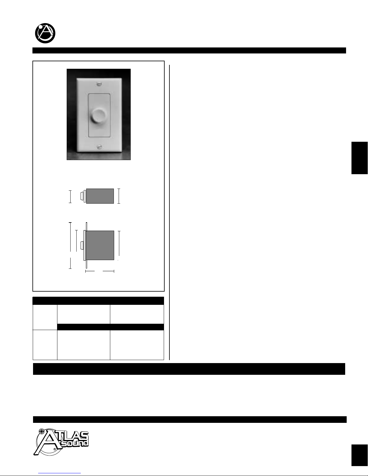
DWT-8 Series
Shown with Decora-style subplate (Supplied)
Top Vie w
Side View
111⁄16"
15⁄16"
213⁄16"
41⁄8
"
25⁄8"
21⁄2"
a
REQUIRED
AMPLIFIER
OUTPUT
IMPEDANCE
IMPEDANCE JUMPER SETTINGS
MAX. QTY. 8-OHM MAX. QTY.4-OHM
LOUDSPEAKER PAIRS LOUDSPEAKER PAIRS
JUMPER SETTING JUMPER SETTING
@1X @2X @4X @8X @1X @2X @4X @8X
8-Ohm 1 2 4 8 0 1 2 4
4-Ohm 2 4 8 16 1 2 4 8
2-Ohm 4 8 16 32 2 4 8 16
1-Ohm 8 16 32 64 4 8 16 32
a
MODEL POWER INSERTION FREQUENCY PLATE REQUIRES
SERIES* RATING IMP. LOSS RESPONSE STEPS TYPE STYLE (ORDER SEPARA TEL Y) WEIGHT
DWT-8 50 Watts 8 Ohm .5dB 20 Hz - 6 @ 3dB Stereo Decora** 12-18 Gauge Wire & 1 lb
20 kHz 3 @ 6dB 15⁄16" x 25⁄8" 20 cu. in. E.O. Box (by others***) (.45 Kg)
(-3dB, +0) 1 @ 9dB
1@ 28dB
(11 Steps Total, plus "off")
Specifications subject to change without notice
FOUR
Page 2
Specifications subject to change without notice
© 2001 Atlas Sound LP Printed in U.S.A. 000801 PN 389516 SL4-1570
1601 JACK MCKAY BLVD. / ENNIS, TEXAS 75119 U.S.A. / TELEPHONE: (800) 876-3333 / FAX (800) 765-3435
Stereo Amplifier / Receiver
capable of handling a 2-ohm load
A
M
P S
U
P
P
L
Y
LL+
R+
R-
Connect additional volume controls
if desired. Confirm maximum quantity
by referencing the impedance
chart on front side.
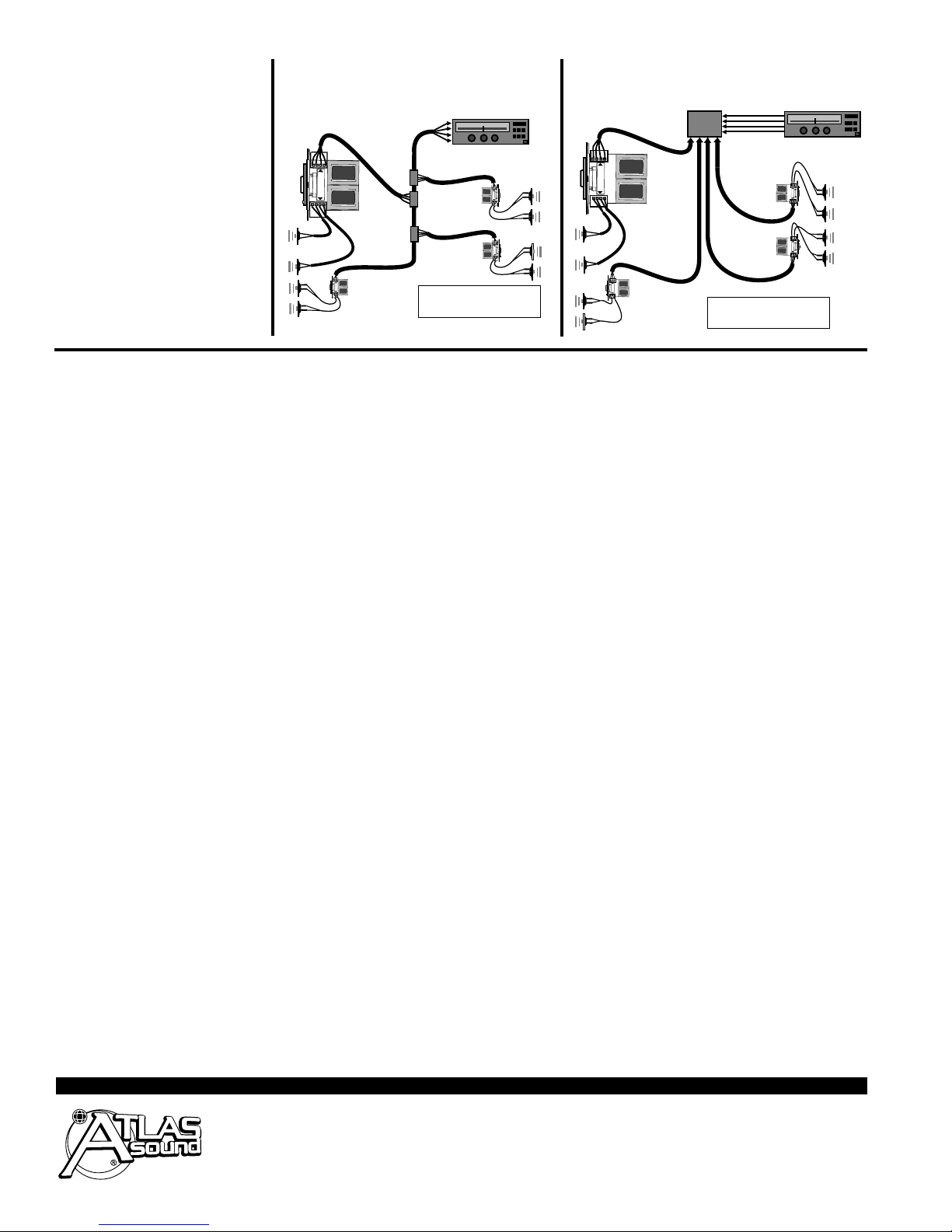
REFERENCES TO WHISPERTOUCH ON THIS THIS INSTALL SHEET APPLY ONLY TO MODEL DWT-8
“Daisy Chain”
Wiring
These diagrams show examples of a system that uses 8-ohm loudspeakers and an
amplifier capable of handling a 2-ohm load.
Set each WhisperTouch volume control
impedance jumper according to the chart
on the front of this sheet.
The wiring depicts how volume controls
can be daisy chained or wired in home run
fashion from each volume control to the
amplifier.
"MEL" Main Equipment Location
Connector
Block
Stereo Amplifier / Receiver
capable of handling a 2-ohm load
AM
P SU
PPLY
LL+
R+
R-
Connect additional volume controls
if desired. Confirm maximum quantity
by referencing the impedance
chart on front side.
“Home Run”
Wiring
INSTALLATION
INSTRUCTIONS
FOR WHISPERTOUCH
MODELS DWT-8
Mounting Location:
Volume controls should be placed in accessible
wall locations that are close to entryways, exits,
light switches, or telephones. They may also be
ganged with other low voltage* controls such as
keypads or infrared repeaters.
*Note: WhisperTouch should not be mounted into
the same electrical box used for a 110-volt device
—even if the box says it is partitioned for this purpose. Speaker wires may pick up electrical noise
which will be transmitted as a buzzing or popping
sound to the loudspeakers.
Mounting Requirements:
Switched WhisperTouch units are slightly taller,
wider, and deeper than most volume controls and
requires a 20 cu in. E.O. box with a minimum
inside depth of 2.75" and a minimum inside height
of 2.985". Recommended boxes for new construction include: Carlon PVC switch box #B-120A, and
RACO PVC outlet box. For retrofit applications,
CADDY drywall trim ring #MPLS may be used.
Calculating the proper Impedance
settings for the system:
WhisperTouch is an impedance-matching stereo volume control that allows multiple loudspeaker pairs
and
volume controls to be connected, in parallel, without
the additional cost of a separate impedance-matching device. For flexibility in system design,
WhisperTouch has three impedance matching capabilities: 2X, 4X and 8X, as well as a 1X non-impedance matching setting that allows the unit to be used
as a standard 8 Ohm
volume control.
To determine which setting should be used (1X, 2X,
4X and 8X) you will need to know the number of
loudspeaker pairs, the loudspeaker impedance,
and the load capability (output impedance) of the
amplifier. Most amplifiers will handle a load down to
four or two ohms with some going as low as 1 ohm.
Using the chart on page one; cross reference the
number of loudspeaker pairs to the amplifier impedance. Notice that the 4X jumper setting will allow
twice as many loudspeaker pairs.
Example: If you have 8 pairs of 8-ohm loudspeakers and an amplifier capable of handling a 4 ohm
load you must set WhisperTouch at the 4X setting
for the amplifier to drive all 8 pairs of speakers at
full volume. Note that the 2X setting allows only 4
pairs of 8-ohm loudspeakers to operate on a 4 ohm
load. If however, you could select an amplifier with
a 2 ohm output impedance, the same 8 loudspeakers could operate on a 2 ohm load (at the 2X setting) or 16 loudspeaker pairs (at the 4X setting).
Whenever possible, the lowest jumper setting for a
given amplifier should be selected.
Changing Impedance Jumpers:
Once the proper impedance setting is determined,
locate the impedance jumpers (black plastic modules) on the back side of the circuit board. One
jumper is for the right channel, the other for the left.
Next, locate the 1X, 2X, 4X and 8X settings on the
circuit board for each channel. If the settings are
correct, continue to the next step. If the settings
need to change, simply slide the jumper modules
off and reinstall them on to the correct two pins.
Limitations:
WhisperTouch limits the degree of impedance matching to eight times so that music quality and overall
performance is not sacrificed. We do not recommend
that any quality, multi-room music system be connected to a device which provides 16X impedance
matching as it may limit the amplifier’s power and
system performance.
Prewiring and Installation:
A.Mount the outlet box or plaster ring in the wall
(see mounting requirements). Each room’s wiring
can be individually run back to the amplifier (home
run) or connected from one room to the other
(daisy chain). The daisy chain wiring method connects one set of speakers with volume control in
parallel to the next, using connection block or
crimp connectors in between. This method has the
advantage of requiring less wiring for the system
rough-in, but allows for little or no system upgrading for future applications.
With either method, be sure to mark the cable connected to the amplifier as [INPUT] and write down
the color codes you have designated for the left
channel, right channel, positive, and negative leads.
B.If using the "Home Run" wiring method, each
rooms speaker/volume control wiring should be individually run back to the Main Equipment Location
"MEL" in a "home-run" fashion. Run a total of four
conductors of speaker cable from the amplifier location to each room's volume control box.
Note: Many building and fire codes require cable
to be CL-2, CL-3, or FT4 rated. Check with your
local building inspector before prewiring.
C..Next, run a two-conductor speaker cable from
the outlet box to the corresponding left and right
speakers. Mark each cable [LEFT] and [RIGHT]
and determine the polarity of each channel (positive and negative).
D..Cut the cable accordingly, allowing enough cable
to hang outside the outlet box, to properly connect
the volume control. Tuck the cable back into the
outlet box to prevent damage during drywall installation.
E. If desired, the terminal block may be removed
from the volume control to more easily accomodate
wiring. Strip 1/4" of insulation off each conductor
and insert the wires into the terminal block. Tighten
the terminal block screws frimly and re-install the
terminal block onto the pins.
F. Tuck the excess cable from inside the outlet box
back out into the wall or fold wires carefully while
inserting the volume control into the outlet box.
Position the volume control so that the front bracket
lines up with the mounting holes on the box. In
some cases, WhisperTouch may be a tight fit
requiring it to be inserted on the right side of the
outlet box and then slid left into the center position.
Note: In retrofit applications, metal extension plates
and non-recommended outlet boxes may require
field modification to accept the units’ higher and
deeper profile.
G. Secure unit with supplied screws. We recommend loosening the screws 1/4 turn to allow 1/4"
movement side-to-side and front-to-back. This will
allow the face plate to fit flush when the cover plate
is installed.
H.Mount the cover plate and tighten the screws.
 Loading...