

Page 1
ICE CREAM FREEZER-WDF & WDF-L SERIES
Service and Installation Manual
Please read this manual completely before attempting to install or operate this equipment!
Notify carrier of damage! Inspect all components immediately. See page 1.
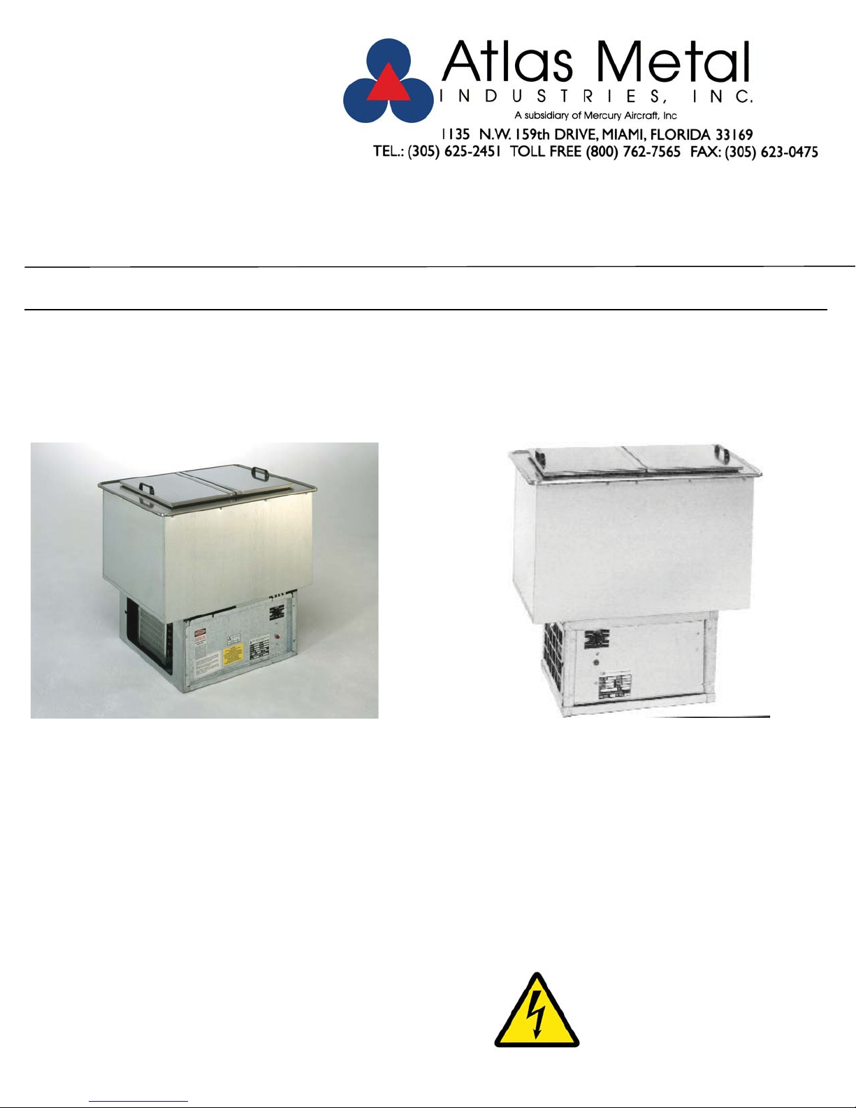
WDF
DROP-IN ICE CREAM FREEZER
REFRIGERATED, SELF CONTAINED
WDF-L
DROP-IN SLIM-LINE ICE CREM
FREEZER , REFRIGERATED, SELF
CONTAINED
Effective Date: 2017
IMPORTANT INFORMATION
READ BEFORE USE
Page 2

CONTENTS
RECEIVING & INSPECTING EQUIPMENT....................................................................................................................................................................................1
SERIAL AND MODEL # LOCATION..............................................................................................................................................................................................1
WDF - SPECIFICATIONS, FEATURES AND ACCESSORIES.....................................................................................................................................................2
ELECTRICAL CHARACTERISTICS, CUT-OUT REQUIREMENTS AND REFRIGERATION CHART...................................................................................3
WDF-L - SPECIFICATIONS, FEATURES AND ACCESSORIES.................................................................................................................................................4
ELECTRICAL CHARACTERISTICS, CUT-OUT REQUIRMENTS AND REFRIGERATION CHART.....................................................................................5
WDF & WDF-L INSTALLATION, OPERATION AND S/S MAINTENANCE...........................................................................................................................6
PARTS LIST...........................................................................................................................................................................................................................................7
TROUBLE SHOOTING GUIDE..........................................................................................................................................................................................................8
ELECTRICAL SCHEMATIC.................................................................................................................................................................................................................9
LIMITED WARRANTY.........................................................................................................................................................................................................................10
WARRANTY INFORMATION............................................................................................................................................................................................................11
RECEIVING AND INSPECTING THE EQUIPMENT
1. VISUALLY INSPECT THE SHIPPING CRATE. DAMAGE SHOULD BE NOTED AND REPORTED TO THE DELIVERING CARRIER.
2. IF DAMAGED, OPEN AND INSPECT CONTENTS WITH CARRIER.
3. IF CRATE IS NOT DAMAGED AND THERE IS CONCEALED DAMAGE TO THE EQUIPMENT, NOTIFY THE CARRIER. NOTIFICATION MUST BE
MADE VERBALLY AND IN WRITING.
4. REQUEST AN INSPECTION BY THE SHIPPING COMPANY FOR THE DAMAGED EQUIPMENT WITHIN 10 DAYS FROM RECEIPT OF THE
EQUIPMENT
5. FREIGHT CARRIERS CAN SUPPLY THE NECESSARY FORMS ON REQUEST.
6. SAVE ALL CRATING MATERIALS UNTIL INSPECTION HAS BEEN MADE OR WAIVED.
SERIAL NUMBER LOCATION
THE SERIAL AND MODEL # CAN BE FOUND ON THE CONDENSING UNIT ENCLOSURE - SEE OPERATORS SIDE CONTROL PANEL WHEN
CALLING ATLAS FOR PARTS AND SERVICE ALWAYS HAVE THIS INFORMATION AVAILABLE.
SERIAL #: _______________________________________________________
MODEL #:_______________________________________________________
INSTALLATION DATE: _____________________________________________
Page 3
Project: ___________
Item No.: ___________
Quantity: ___________
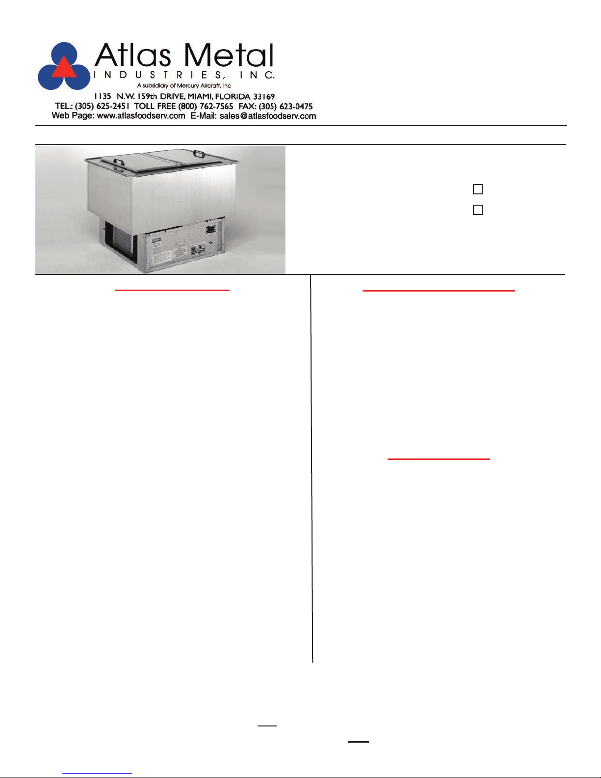
DROP-IN SERVING EQUIPMENT
ICE CREAM
FREEZER
Refrigerated,
Self-Contained
WDF-2
SPECIFICATIONS
TOP: Constructed of 18 gauge, type 304 stainless steel, die
stamped with a raised perimeter bead. There shall be a solid
vinyl gasket under the beaded edge to form a seal to the
counter top, thus preventing seepage or marring the counter
top.
LINER: The inner liner shall be 18 gauge, type 304 stainless
steel, one piece construction, all welded, ground and polished
to a uniform finish. All corners are coved with a minimum 1/4"
radius on the horizontal edges and a minimum 3/4" radius on
the vertical edges. The liner has copper tubing firmly soldered
to the exterior sides and bottom. The unit is provided with an
all stainless steel insulated, hinged, lift off lid, with plastic
coated pulls.
INSULATION: The unit is fully insulated with high density
polystyrene, 2-1/2" thick on all sides, and enclosed with a 22
gauge galvanized steel outer liner.
REFRIGERATION SYSTEM: The compressor housing shall
be fabricated from 14 gauge galvanized and bolted to the
base of the unit. A fully self-contained condensing unit is provided with a hermetically sealed compressor and a thermostat
control. The system is fully charged with CFC free refrigerant
and ready to operate.
WDF-2
WDF-3
STANDARD FEATURES
g
Fully insulated for maximum efficiency and energy
savings
g
Removable S/S hinged lid
g
Factory applied gasket - makes installation a snap and
seals units to the counter top, thus eliminating
seepage
Ideal for frozen dessert or use it as a mug or plate
g
chiller
g
1-Year Parts & Labor Warranty
g
NSF Certified and UL Listed
ACCESSORIES
g
5YW - 5-Year Compressor Warranty
g
Hinged Plexiglas Lid
g
LLD - Lid Locking Device
g
2060-1 - Condensate Evaporator
g
RS - Remote On/Off Switch for counter mounting
g
* 220 Volt - 50 Cycle Compressor
NOTE: Proper ventilation must be provided in counter.
ELECTRICAL: The unit will be wired for 15 amps., 120 volt,
single phase operation, with an on/off thermostat switch and
pilot light. A 6' long, 3-wire cord and plug (NEMA 5-15P) will
be provided.
Specifications subject to change without notice.
*Please see Operation & Installation Manual for ALL
* Units with these accessories are not currently UL listed.
operation and maintenance details.
DI-41
Page 4
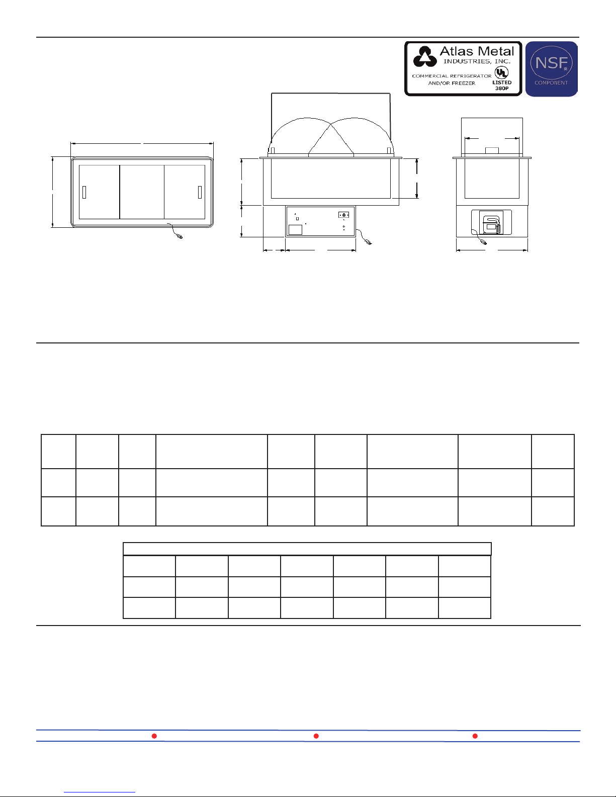
WDF-2: 22-1/2” I.D.
WDF-3: 36-1/4” I.D.
24”
A
PLAN VIEW
16”
10-3/4”
B 21-1/2”
ELEVATION
16-1/2”
13-1/2”
21-3/4”
END VIEW
MODEL “A” “B”
WDF-2
WDF-3
29-3/4”
(75.5cm)
43-1/2”
(110.4cm)3”(7.6cm)
6-7/8”
(17.4cm)
16-1/2” X 22-1/2” X 13-1/2”
16-1/2” X 36-1/2” X 13-1/2”
INTERIOR
DIMENSIONS
(41.9 X 57.1 X 34.2cm)
(41.9 X 92.7 X 34.2cm)
REFRIGERATION CHART
MODEL HP REF. OZ.
WDF-2 1/4 134A 4 min 3 in 129 1070
WDF-3 1/4 134A 5 min 3 in 129 1070
WDFX - REFRIGERATED ICE CREAM FREEZER
WITHOUT COMPRESSOR
Units include Refrigerated Ice Cream Freezer,
Thermostat, Cap Tube & Drier (for hook up in field
by others)
CU. FT.
CAPACITY
4.5
7.8
LBS.
CAPACITY
100
(45.3kg)
150
(68kg)
LOW
PSIG.
ELECTRICAL
CHARACTERISTICS
6.8amps. X 120V X
1/4HP
6.8amps. X 120V X
1/4HP
HIGH
PSIG.
M10 90A
CUT-OUT
REQUIRED
22-1/4” X 28”
(56.5 X 71.1cm)
22-1/4” X 41-3/4”
(56.5 X 106cm)
BTU
COMPRESSORS FOR REMOTE INSTALLATIONS
2029-1 - 1/4 HP for WDFX-2 & 3
SHIP WT.
(LBS.)
194
(88kg)
232
(105.2kg)
Atlas Metal Industries 1135 NW 159th Dr. Miami, FL 33169 (800) 762-7565 Fax: (305) 623-0475 atlasfoodserv.com
DI-42
9/17-sc
Page 5

Project: ___________
Item No.: ___________
Quantity: ___________
SLIM-LINE DROP-IN SERVING EQUIPMENT
SLIM-LINE
ICE CREAM
FREEZER
Refrigerated,
WDF-L
SPECIFICATIONS
TOP: Constructed of 18 gauge, type 304 stainless steel, die
stamped with a raised perimeter bead. There shall be a solid
vinyl gasket under the beaded edge to form a seal to the
counter top, thus preventing seepage or marring of the
counter top.
LINER: The inner liner shall be 18 gauge, type 304 stainless
steel, one piece construction, all welded, ground and polished
to a uniform finish. All corners are coved with a minimum 1/4”
radius on the horizontal edges and a minimum 3/4” radius on
the vertical edges. The liner has copper tubing firmly soldered
to the exterior sides and bottom. The unit is provided with an
all stainless steel, insulated, hinged, lift off lid, with plastic
coated pulls.
INSULATION: The unit is fully insulated with high density
polystyrene, 2-1/2" thick on all sides, and enclosed with a 22
gauge galvanized steel outer liner.
REFRIGERATION SYSTEM: The compressor housing shall
be fabricated from formed angles and bolted to the base of
the unit. A fully self-contained condensing unit is provided with
a hermetically sealed compressor and a thermostat control.
The system is fully charged with CFC free refrigerant and
ready to operate.
Self-Contained
WDF-L
STANDARD FEATURES
g Slim-line configuration - it can install in counters only
16-1/2” wide
g
Fully insulated for maximum efficiency and energy
savings
g
Removable S/S hinged lid
g
Factory applied gasket - makes installation a snap and
seals units to the counter top, thus eliminating
seepage
Ideal for any frozen dessert or use it as a mug or plate
g
chiller
g
1-Year Parts & Labor Warranty
g
NSF Certified and UL Listed
ACCESSORIES
g
5YW - 5-Year Compressor Warranty
g
Hinged Plexiglas Lid
g
LLD - Lid Locking Device
g
2060-1 - Condensate Evaporator
g
RS - Remote On/Off Switch for counter mounting
g
* 220 Volt - 50 Cycle Compressor
NOTE: Proper ventilation must be provided in counter.
ELECTRICAL: The unit will be wired for 15 amps., 120 volt,
single phase operation, with an on/off thermostat switch and
pilot light. A 6' long, 3-wire cord and plug (NEMA 5-15P) will
be provided.
Specifications subject to change without notice.
*Please see Operation & Installation Manual for ALL
* Units with these accessories are not currently UL listed.
operation and maintenance details.
DI-43
Page 6

27-3/4”
16-1/2”
PLAN VIEW
MODEL
WDF-L
22-1/2” X 11-1/4” X 13”
(57.2 X 28.6 X 33cm)
SIZE
W x L x D
16”
10-3/4”
CU. FT.
CAPACITY
4-1/2”
1.9
18”
ELEVATION
LBS.
CAPACITY
65
(29.5kg)
13”
ELECTRICAL
CHARACTERISTICS
2.4 amps. - 120V
1/5 HP
CUT-OUT
REQUIRED
26” X 15”
(66 X 38.1cm)
13-3/4”
SHIP WT.
(LBS.)
158
(54kg)
10-3/4”
END VIEW
MODEL HP REF. OZ.
WDF-L 1/5 134A 2.5 min 3 in 129 505
WDF-LX - REFRIGERATED ICE CREAM FREEZER
WITHOUT COMPRESSOR
Units include Refrigerated Ice Cream Freezer,
Thermostat, Cap Tube & Drier (for hook up in field
by others)
Atlas Metal Industries 1135 NW 159th Dr. Miami, FL 33169 (800) 762-7565 Fax: (305) 623-0475 atlasfoodserv.com
DI-44
REFRIGERATION CHART
LOW
PSIG.
COMPRESSORS FOR REMOTE INSTALLATIONS
2029 - 1/5 HP for WDF-LX
HIGH
PSIG.
BTU
M10 90A
9/17-sc
Page 7

ICE CREAM FREEZERS
WDF & WDFL SERIES
---------------------------------------------------------------------------------------------------------------------------------------------------------
INSTALLATION
Provide the correct counter cut-out opening (see chart below) and drop in. The vinyl gasket assures
complete seating. A non-toxic silicone seal may be used between the gasket and counter top (not
required).
MODEL NUMBER CUT-OUT SIZE
WDF-2 22 1/4 X 28
WDF-3 22 1/4 X 41 3/4
WDF-L 15 X 26
When installing unit in a counter, it is recommended that the operator side of the counter be completely
open for air circulation. When this is not possible, such as in an island counter, it is recommended that two
grill openings are provided approximately 18” x 18” of free air for intake and exhaust at the opposite ends
of the counter.
The unit is supplied with a power cord and NEMA plug. Refer to the data plate on the compressor housing
for the amperage and voltage information. Use a licensed electrician when installing power source.
---------------------------------------------------------------------------------------------------------------------------------------------------------
OPERATION
The unit is ready to operate as soon as it is plugged in. The thermostat has an off position and numbers
from #1 through #7 (number 7 is the coldest). The unit should be turned off every day after used and
turned on one hour before serving.
---------------------------------------------------------------------------------------------------------------------------------------------------------
MAINTENANCE
NEVER CLEAN PANS WITH A CHLORIDE BASED PRODUCT. CHLORIDES OR IMPROPER
CLEANING COULD SCAR, MARK AND/OR CORRODE PANS. DO NOT USE STEEL WOOL OR
ABRASIVE PRODUCTS. TO CLEAN USE SOAPY WARM WATER, RINSE THOROUGHLY TO
REMOVE ALL RESIDUES. FAILURE TO MEET THESE CONDITIONS WILL VOID
WARRANTY.
CLEAN CONDENSER COIL REGULARLY.
Page 8

Subsidiary of Mercury Aircraft, Inc.
1135 N.W. 159th DR., MIAMI, FL 33169
PHONE (305) 625-2451, (800) 762-7565, FAX (305) 623-0475, E-mail: sales@atlasfoodserv.com
PARTS LIST ICE CREAM FREEZERS
WDF & WDFL SERIES
1
2
3
4
5
6
8
ITEM NUMBER PART NUMBER DESCRIPTION
1
2
3 6043-0 Lid Handles
4 7002-0+Model # Vinyl Bead Gasket
5 1003-0 Power Cord with Plug
6 2043-0 Thermostat
7 1099-0 Pilot Light
8
9
10 7003-0+Model # Throat Gasket (Not Shown)
11 2027-0 0.031 Cap Tube for 1/5 H.P. Comp. WDFL only (Not Shown)
12 2026-0 0.042 Cap Tube for 1/4, H.P. Comp. (Not Shown)
13 2025-0 Drier (Not Shown)
14 7030-0 WDFL Plastic Underlid (Not shown)
15 7031-0 WDF-2-3 Plastic Underlid (Not Shown)
16 7032-0 WDF-3 Center Underlid (Not Shown)
16 600008 Thermostat Knob
S11054 + Model # WDF Lid Assembly
S33155-0 WDFL Lid Assembly
S11014-0 WDF Hinge
S81809-0 WDFL Hinge
2029-0 1/5 H.P. Compressor WDFL
2029-1 1/4 H.P. Compressor WDF-2 & 3
4043-1 Handle Screws (Not Shown)
7
WDF-2
SHOWN
Page 9

Subsidiary of Mercury Aircraft, Inc.
1135 N.W. 159th DR., MIAMI, FL 33169
PHONE (305) 625-2451, (800) 762-7565, FAX (305) 623-0475, E-mail: sales@atlasfoodserv.com
Refrigerated Drop-In Trouble Shooting Guide
Symptom Probable Cause
Unit not plugged in.
No power at receptacle.
Unit will not run
Condenser runs but
short cycles
Thermostat and or switch not in the on position.
Unit may be in a defrost cycle (if supplied) wait approximately 20 min.
Call factory for service at 1-800-762-7565
Condenser coil dirty
Inadequate ventilation.
Call factory for service at 1-800-762-7565
Condenser runs
constantly.
Food product not
cold enough.
Condenser coil dirty.
Inadequate ventilation.
Unit installed in a hot location
Call factory for service at 1-800-762-7565
NOTE: WF series runs constantly.
Food product must be chilled to 33-35 deg. when placed in unit.
Air movement over food product.
Food product not being stirred or rotated.
Call factory for service at 1-800-762-7565
Page 10

Page 11

LIMITED WARRANTY
Atlas Metal Industries, Inc. warrants to the Purchaser of this product that the
same shall be free from defects in the workmanship and material for a period of
one year from the date of original installation of the equipment, but not to exceed
eighteen (18) months after date of shipment from factory. During this period of
time Atlas Metal Industries, Inc. will replace all defective parts and will pay for
authorized replacement labor. Replacement and installation of such parts and
labor shall be provided only upon prior written authority of Atlas Metal Industries,
Inc.
The Refrigeration warranty is for a twenty (20) month time period and includes
supplying the compressor at a no charge basis provided the damage to the
compressor was not caused by the customer or end user. Authorized
replacement labor will be paid for a period of one year from date of installation.
Freight costs for defective unit to and from Atlas Metal Industries, Inc. are not
included, and all defective parts must be returned to the factory freight prepaid
for evaluation. ALL WARRANTY LABOR MUST BE AUTHORIZED BY ATLAS
METAL INDUSTRIES, INC. PRIOR TO THE ACTUAL WORK BEING DONE.
This warranty does not apply to any equipment or any part thereof, which has
been subjected to shipping damage, improper voltage, alteration, abuse or
misuses, and does not cover loss of food, other products, or damage to property
due to mechanical or electrical malfunction.
THERE ARE NO WARRANTIES WHICH EXTEND BEYOND THE
DESCRIPTION OF THE FACE HEREOF. SELLER DISCLAIMS ANY IMPLIED
WARRANTY OF MERCHANTABILITY OF THE GOODS OR THE FITNESS OF
THE GOODS FOR ANY PURPOSE AND BUYER AGREES THAT THE GOODS
ARE SOLD “AS IS.”
Page 12

WARRANTY INFORMATION
In order to have your invoice approved for
payment by the factory, please note the following:
_______________________________________________
An authorization number must
be obtained from
the factory prior to performing any warranty
service.
_______________________________________________
Atlas Metal will not approve excessive labor
due to poor
access to the unit being serviced. If design does not
allow reasonable access, contact the factory.
_______________________________________________
All travel time that exceeds 100 miles round trip
must
_____________________________________________________________________________________
Thank You:
Warranty service Dept.
be authorized by the factory.
 Loading...