

Page 1
Page 2

Read this entire manual before operation begins.
Record below the following information which is located on the serial number
data plate.
Serial No.
Model No.
Date of Installation
Page 3

Contents
Introduction . . . . . . . . . . . . . . . 5
General Information . . . . . . . . . . . 8
Transportation, Unpacking And Storage . 13
Installation . . . . . . . . . . . . . . 14
Operation . . . . . . . . . . . . . . . 22
Infl ating . . . . . . . . . . . . . . . . 30
Accessories . . . . . . . . . . . . . . 33
Maintenance . . . . . . . . . . . . . . 35
Trouble-Shooting. . . . . . . . . . . . 37
Electric And Pneumatic Diagram. . . . . 39
Warranty . . . . . . . . . . . . . . . 42
Page 4
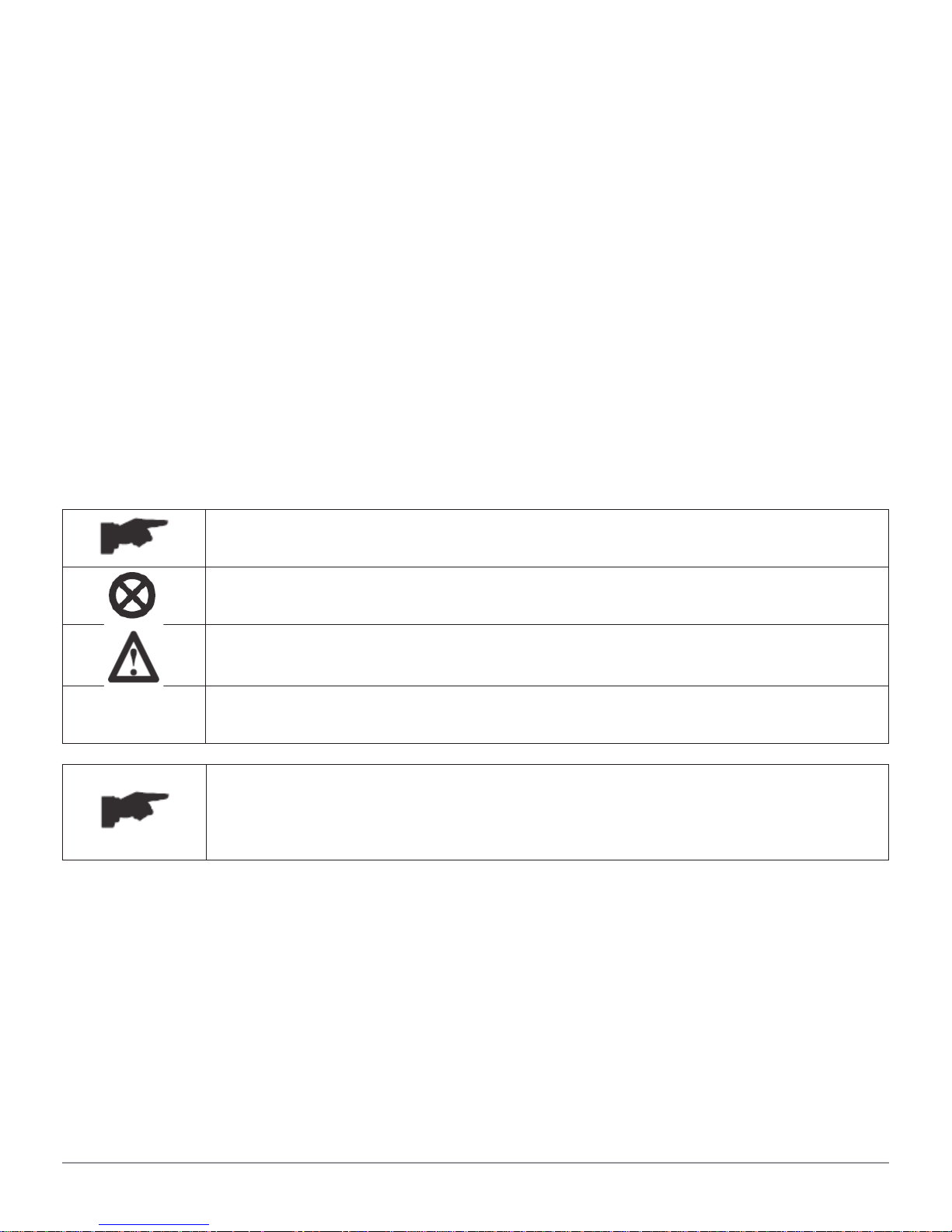
Printing Characters And Symbols
Throughout this manual, the following symbols and printing characters are used
to facilitate reading:
Indicates the operations which need proper care
Indicates prohibition
Indicates a possibility of danger for the operators
BOLD TYPE Important information
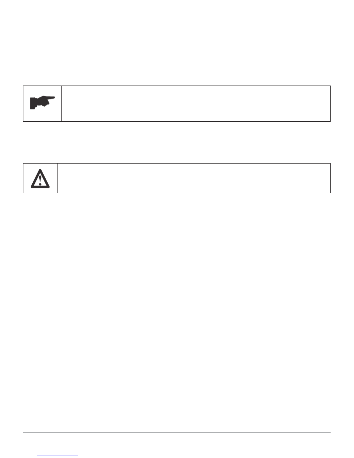
WARNING: before operating the machine, read carefully
Chapter 7 Installation where all proper operations for a
better functioning of the machine are shown.
4
TC255
Page 5

Introduction
1.1 Introduction
Thank you for purchasing an Atlas tire changer. The machine has been
manufactured in accordance with the very best quality principles. Follow the
simple instructions provided in this manual to ensure the correct operation and
long life of the machine. Read the entire manual thoroughly and make sure you
understand it.
1.2 Machine Identifi cation Data
A complete description of the “Tire Changer Model” and the “Serial number”
will make it easier for our technical assistance to provide service and will
facilitate delivery of any required spare parts. For clarity and convenience, we
have inserted the data of your tire changer in the box below. If there is any
discrepancy between the data provided in this manual and that shown on the
plate fi xed to the tire changer, the latter should be taken as correct.
LOGO
Type:
Volt: Amp: Kw:
Ph: Hz:
Year of manufacturing:
Air supply: 8-10 bar (115 – 145 PSI)
1.3 Manual keeping
For a proper use of this manual, the following is recommended:
• Keep the manual near the machine, in an easily accessible place.
• Keep the manual in an area protected from the damp.
Introduction 5
TC255
Page 6
• Use this manual properly without damaging it.
• Any use of the machine made by operators who are not familiar with the
instructions and procedures contained herein shall be forbidden.
This manual is an integral part of the product: it shall be given to the new owner
if and when the machine is resold.
The illustrations have been made out of prototypes pictures. It
is therefore possible that some parts or components of standard
production differ from those represented in the pictures.
1.4 General Safety Precautions
The tire changer may only be used by specially trained and
authorized expert personnel.
• Any tampering or modifi cation to the equipment carried out without the
manufacturer’s prior authorization will free him from all responsibility for
damage caused directly or indirectly by the above actions.
• Removing or tampering with safety devices immediately invalidates the
guarantee.
• The tire changer comes complete with instruction and warning transfers
which are designed to be long-lasting. If they should for any reason be
damaged or destroyed, please ask immediately for replacements from the
manufacturer.
1.5 Scrapping
When your machine’s working life is over and it can no longer be used, it must
be made inoperative by removing any connection to power sources.
These units are considered as special waste material, and should be broken
down into uniform parts and disposed of in compliance with current laws and
regulations.
If certain parts are pollutants or non-biodegradable, deliver them to the
appropriate handling station.
Introduction 6
TC255
Page 7

To The Reader
Every effort has been made to ensure that the information contained in this
manual is correct, complete and up-to date. The manufacturer is not liable for
any mistakes made when drawing up this manual and reserves the right to make
any changes due the development of the product, at any time.
Introduction 7
TC255
Page 8
General Information
2.1 Intended Use
• This automatic tire changer has been designed and manufactured
exclusively for removing and mounting tires from/onto rims from 10” to
30” and a maximum diameter of 47”.
• In particular THE MANUFACTURER cannot be held responsible for any
damage caused through the use of this tire changer for purposes other
than those specifi ed in this manual, and therefore inappropriate, incorrect
and unreasonable.
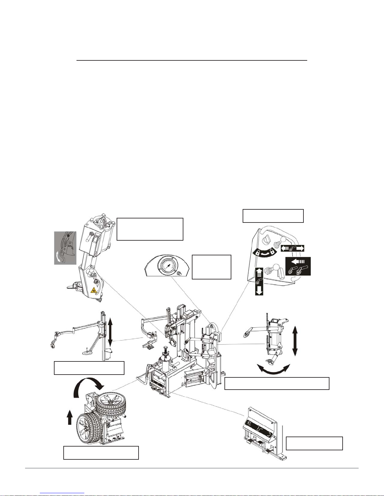
2.2 Description Of Machine
Control panel
Leverless
Mounting tools
Bead press arm
Wheel positioner
Infl ation
System
Bead breaking carriage
Front panel
General Information 8
TC255
Page 9
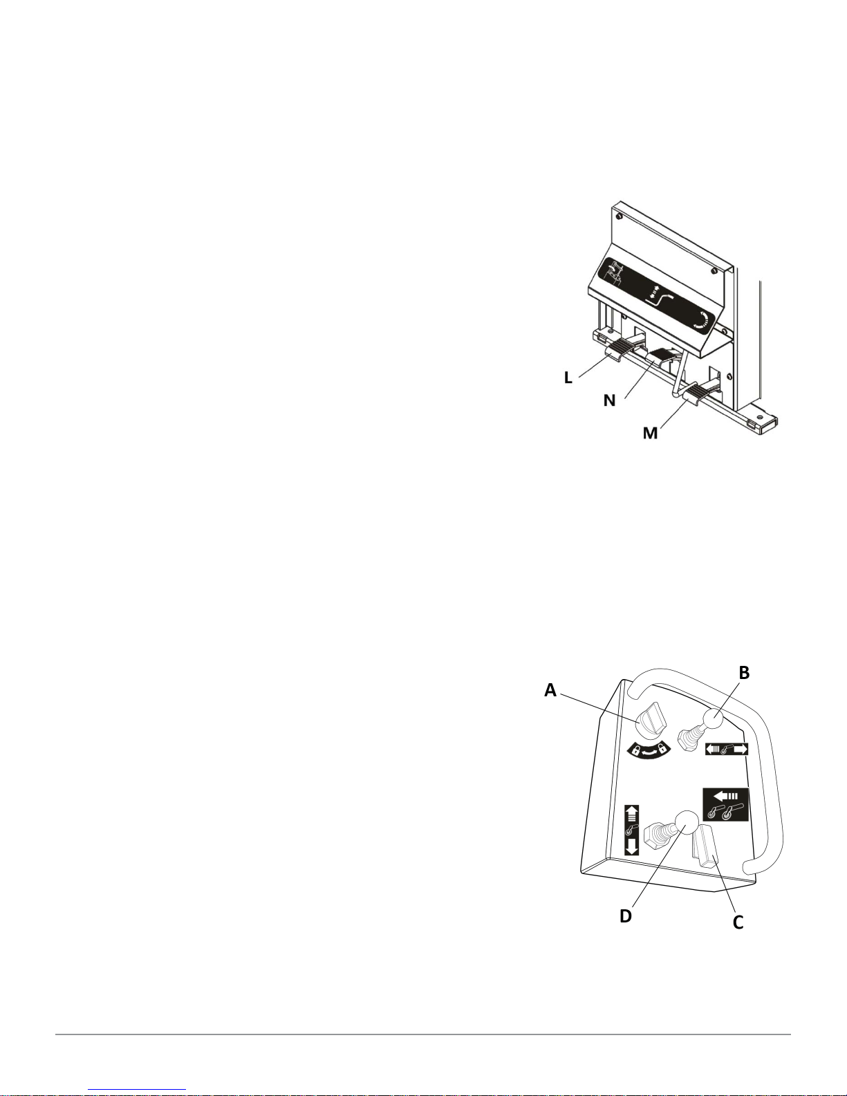
2.3 Description Of Controls
2.3.1 Pedals On Front Panel
PEDAL “L”
This pedal is used to tilt back the vertical arm out of the working position.
PEDAL “M”
This pedal is used to rotate the spindle clockwise or
anticlockwise, in slow or fast rotation mode.
PEDAL “N”
This pedal is used to lift the tire from the ground onto
the spindle fl ange or lower it back down to the ground.
2.3.2 Control Panel
SELECTOR “A”
• When it is selected into LOCKING position, the horizontal movement of the
bead breaker carriage is restricted, and in the meantime the button (C) is
activated.
• When it is selected into UNLOCKING position, the bead breaker arm can
have the normal movements horizontally.
CONTROL LEVER “B”
• When it is pushed leftwards, the bead breaker
carriage moves forwards.
• When it is pushed rightwards, the bead breaker
carriage moves backwards.
BUTTON “C”
• This button works only when the selector (A) is
set in LOCKING position.
• When it is pressed, the bead breaker carriage
makes an over stroke: moves forwards about 1”.
• When it is released, the bead breaker carriage moves back to the initial
position automatically.
General Information 9
TC255
Page 10
CONTROL LEVER “D”
• When it is pushed upwards, the bead breaker arm moves upwards.
• When it is pushed downwards, the bead breaker arm moves downwards.
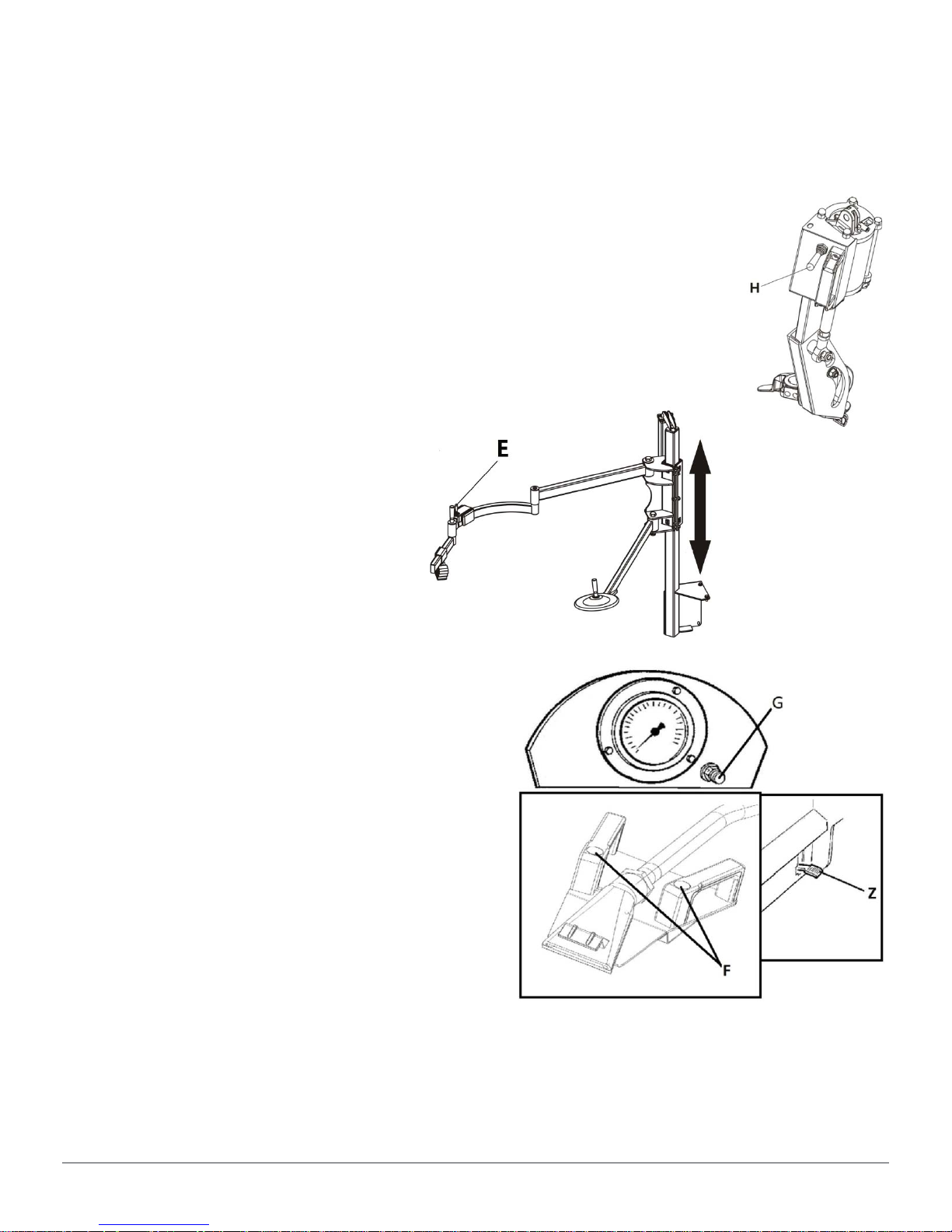
2.3.3 Leverless Mounting Tools
CONTROL LEVER “H”
• When it is pushed downwards, the tool is out of its seat and
moves downwards.
• When it is pushed upwards, the tool moves back in position.
2.3.4 Bead Press Arm
The bead press arm is used to
facilitate mounting and demounting
the run-fl at tire. It can be moved
upwards and downwards by means
of the control lever (E).
2.3.5 GT Infl ation System
The GT infl ating system consists of the
gauge, the tire defl ation button (G) and
the quick blasting device.
• To infl ate the tire, press the pedal
(Z) at side of the machine.
• During infl ation, if the pressure
exceeds the value recommended
by the tire manufacturer, press the
button (G) to defl ate the tire.
• To make the quick blaster, position
the blasting nozzle towards the rim
center just under the rim lip and
press the buttons (F).
General Information 10
TC255
Page 11
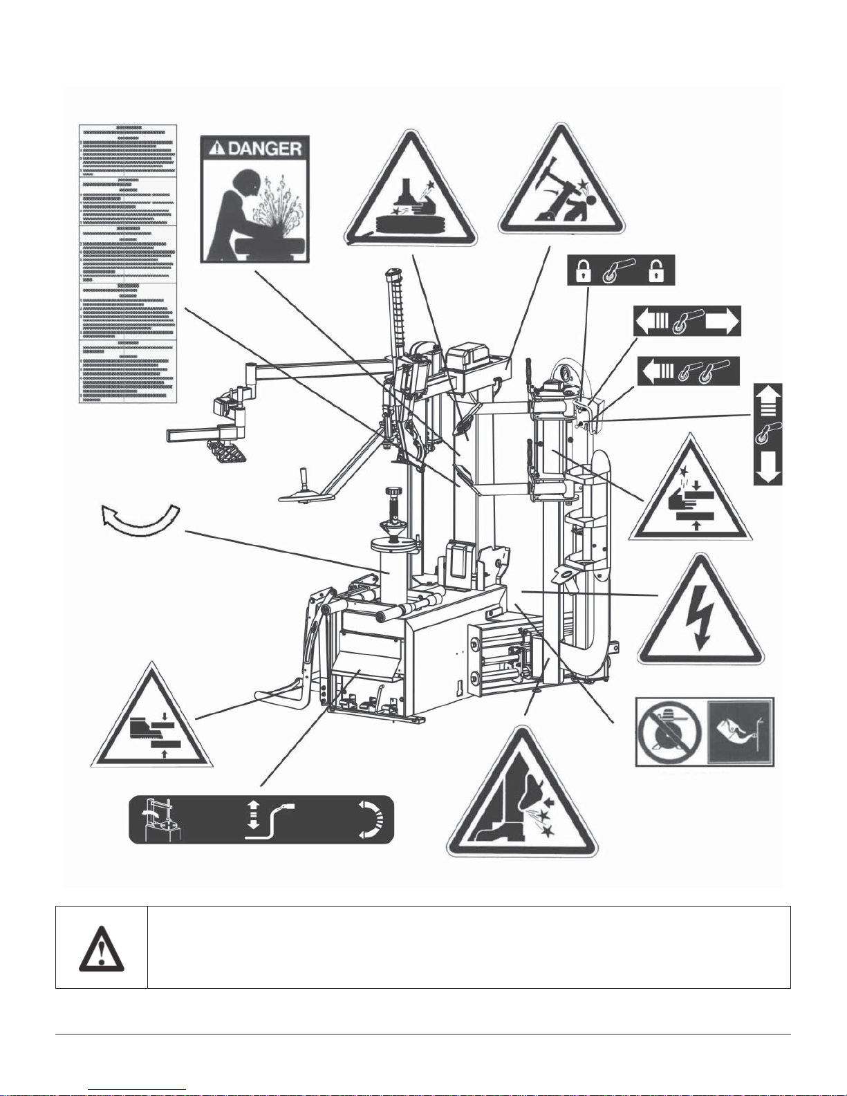
2.4 DANGER WARNING SIGNS
Unreadable and missing warning labels must be replaced
immediately. Do not use or add any object that could prevent
the operator from seeing the labels.
General Information 11
TC255
Page 12

2.5 Technical Specifi cation
Handle rims from 10” – 30”
Max. tire diameter 47” (1200mm)
Max. tire width 15” (390mm)
Max. bead breaking force 2700 lbs force (12000N)
Max. lifting capacity 176 lbs
Working pressure 145 psi (10 bar)
Infl ating pressure device max. 50 psi (3.5 bar)
Power supply voltage 220V/1Ph
Motor power 0.8kw for 220V/3Ph
Rotating speed 6 – 12 rpm
Max spindle torch 885 ft/lbs (1200 NM)
Packing dimension 53” x 55” x 82”
Shipping weight 925 lbs
Noise level in working condition < 70 dB (A)
General Information 12
TC255
Page 13
Transportation,
Unpacking And Storage
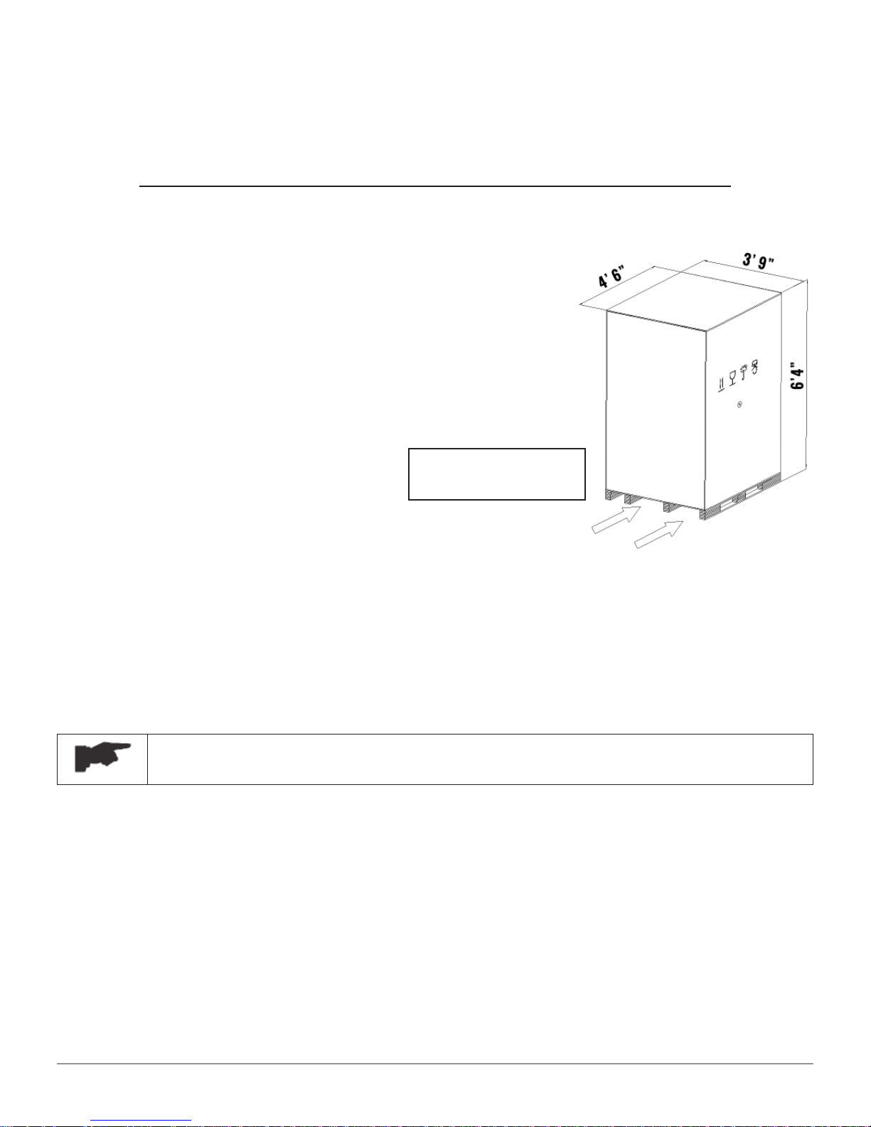
3.1 Transportation
• The tire changer must be transported in its
original packaging and kept in the position
shown on the package itself.
• The packaged machine may be moved by
means of a fork lift truck of suitable capacity.
Insert the forks at the points shown in Figure 1.
Shipping Weight:
925 lbs
Fig. 1
3.2 Unpacking
• Remove the protective cardboard and the nylon bag.
• Check that the equipment is in perfect condition, making sure that no parts
are damaged or missing. Use fi g. 1 for reference.
If in doubt do not use the machine and contact your retailer.
3.3 Storage
In the event of storage for long periods of time, be sure to disconnect all sources
of power and grease the clamp sliding guides on the turntable to prevent them
from oxidizing.
Transportation, Unpacking And Storage 13
TC255
Page 14

Installation
4.1 Space Required
When choosing the place of installation, be sure that it
complies with current safety at work regulations.
• The tire changer must be connected to the main electric power supply and
the compressed air system. It is therefore advisable to install the machine
near these power sources.
• The place of installation must also provide at least the space shown in
pictures 2 - 2/A so as to allow all parts of the machine to operate correctly
and without any restriction.
• If the machine is installed outside it must be protected by a protective
shelter.
The tire changer with electric motor cannot be used in
explosive atmospheres, unless it is a proper version.
Installation 14
Fig. 2
TC255
Page 15

Fig. 2/A
Installation 15
TC255
Page 16

4.2 Parts Assembly
4.2.1 Adjustment of control panel position (ref. fi g. 3)
2
1
Fig. 3
• Loosen screws (1) and (2) slightly, then swing the control panel forward or
backward.
• Tighten the screws after repositioning.
Installation 16
TC255
Page 17

4.2.2 Installation of tool tray (ref. fi g. 4)
2
1
Fig. 4
• Install the support (1) onto the bead breaking arm using the supplied
screws and washers as shown in the fi gure 4, and then tighten the screws;
• Install the tool tray (2) onto the support (1) using the supplied screws and
washers as shown in fi gure 4, and then tighten the screws.
Installation 17
TC255
Page 18

4.2.3 Mounting and connecting the GT tank (ref. fi g.5)
3
1
2
5
4
Fig. 5
• Fix the tank on the back side of the machine body using the proper screw
as shown in the fi gure 5;
• Connect the hose (1) protrudes from the GT pipe to the machine through
the elbow union (2) and the T union (3);
• Connect the hose (4) to the T union (5) situated in the lubricator.
• Connect the hose (4) to the tank through the proper union.
Installation 18
TC255
Page 19

4.3 Commissioning
Any electric connection job must be carried out by
professionally qualifi ed personnel.
Make sure the connection of the phases is right. Improper
electrical hook-up can damage motor and will not be covered
under warranty.
Connect the machine to the electric network, which must be
provided with line fuses, a good earth plate in compliance
with regulations in force and it must be connected to an
automatic circuit breaker (differential) set at 30 mA.
Should the tire-changer be lacking in electric plug, the user
must set one, which is at least 16 A and which conforms
to the voltage of the machine, in compliance with the
regulations in force.
• Connect the machine to the electric mains. Check to make sure the
characteristics of your systems correspond to those required by the
machine.
• Connect the machine to the compressed air system by means of the air
fi ler/lubricator that protrudes from the rear section.
Installation 19
TC255
Page 20

4.4 Operating Tests
The testing procedure must be performed without using
a tire, making sure that no other parts of the machine
interfere with the movements.
• Press pedal (M) down, the spindle (R) should turn in a clockwise direction.
Lift up the pedal, the spindle should turn in an anticlockwise direction. If
the turntable turns in the opposite direction to that shown, reverse two of
the wires in the three-phase plug.
• Press the pedal (L) to tilt the vertical arm (Y). Press it again it returns to its
working position.
• Press the pedal (N) to raise the wheel positioner (O) off the ground to the
same level as the spindle fl ange. Press it again to lower it back down to the
ground.
Installation 20
TC255
Page 21

• Set the locking button (K) in Pos. 2, the arms are unlocked and the
mounting head goes down onto the rim or reaches the minimum working
height.
• Set the button (K) in Pos. 3, the arms are unlocked and the mounting head
goes up to the out-of-work position.
• Set the button (K) in Pos. 1, the mounting bar and the horizontal arm are
locked. The mounting head positions itself automatically at about 1/8” from
the rim.
• Turn the selector (A) into UNLOCKING position, push the lever (B)
leftwards, the bead breaker carriage moves forwards. Push the lever
rightwards, the bead breaker carriage moves backwards.
• Push the lever (D) upwards, the bead breaker arm moves upwards. Push
the lever downwards, the bead breaker arm moves downwards.
• Turn the selector (A) into LOCKING position, press the button (C), the bead
breaker carriage moves forwards about 1”. Release the button, the bead
breaker carriage moves back to the initial position automatically.
• Lift up the handle (U), the upper bead breaker disc arm (S) can be swung
out of the working position. Push the disc arm to the working position and
release the lever, the disc arm can be locked.
• Lift up the handle (Y), the lower bead breaker disc arm (T) can be swung
out of the working position. Push the disc arm to the working position and
release the lever, the disc arm can be locked.
• Push the lever (H) downwards, the mounting hook is out of its seat and
moves downwards. Push it upwards, the tool moves back in position.
NEVER point the nozzle at people. Make sure to hold
the handles of nozzle fi rmly. Failure to do so can be
dangerous.
F
• Press the blasting buttons (F) by
hands, a powerful jet of air can be
come out of the nozzle.
Installation 21
TC255
Page 22

Operation
Do not use the machine until you have read and understood
the entire manual and the warning provided.
Before carrying out any operation, make sure to defl ate the
tire and take off all the wheel balancing weights.
5.1 Clamping The Wheel
• Check to make sure that the tire is defl ated and all balancing weights are
taken off.
• Place the wheel onto the wheel positioner. Make sure the worker area is
free of any object.
• Raise the wheel positioner with the wheel to the full height.
• Slip the wheel onto the top of spindle fl ange with help of rollers.
• Lower the wheel positioner so that the wheel can be positioned on the
center of the spindle fl ange and in the meantime align the driving pin with
one of the wheel lug holes so that the pin goes into the lug hole.
• Select the cone that best fi ts the center hole in the wheels. Slide the cone
onto the center post with the small end towards the central hole of the rim.
Operation 22
TC255
Page 23

• Install the centering post into the spindle fl ange through the central hole of
the rim. Lock the post by turning it clockwise at about 45º.
• Place the quick locking nut to the central post. Tighten it securely.
To mount/demount a tire with an alloy rim, the cone
protection and the spindle fl ange production must be used.
For the wider wheel, the longer driving pin can be supplied
at request.
To mount/demount the tire without a central hole, the
universal adapter should be ordered.
5.2 Breaking The Bead
Bead breaking must be done with the utmost care and
attention. When the bead breaker pedal is operated the bead
breaker disks moves powerfully. Anything within its range of
action can be in danger of being crushed.
During bead breaking operations NEVER touch the side of the
tire by hands.
Chains, bracelets, loose clothing or foreign objects in the
vicinity of the moving parts can represent a danger for the
operator.
To break the upper bead of the tire, do as follows:
• Bring the lower breaker disc (T) out of working
position.
• Set the selector (A) to UNLOCKING position.
• Bring the upper bead breaker disk (S) within 1/8”
- 1/4” of the rim edge by operating the levers (B)
and (D).
• Set the selector (A) to LOCKING position.
• Make sure to rotate the valve at 2 o’clock position
so that the valve cannot be damaged during the
breaking procedures.
Operation 23
TC255
Page 24

• Lower the upper bead breaker disc until it touches the tire. At the same
time start to rotate the spindle fl ange clockwise.
• Push down the lever (D) gently so that the upper
bead breaker disks go down in small increments when
the tire rotates to begin the breaking operations.
• Once the bead breaker disc has created enough
space, start to lubricate carefully with the special
grease on both the rim and the tire bead (ref. fi g.6a).
• Keep turning the spindle fl ange until the upper
bead goes into the rim’s drop center and then keep
pushing the button (C) until the upper bead of tire
is come out of the rim completely. Then release the
button (C).
• Raise and moves back the bead breaker carriage to the initial position by
operating the levers (D) and (B).
• Bring the upper breaker disc (S) out of working position.
To break the lower bead of the tire, do as follows:
• Set the selector (A) to UNLOCKING position.
• Bring the lower bead breaker disk (T) within 1/8” - 1/4” of the rim edge by
operating the levers (B) and (D).
• Set the selector (A) to LOCKING position.
• Raise the lower bead breaker disc until it touches the tire. At same time
start to rotate the spindle fl ange clockwise.
• Raise the lever (D) gently so that the lower bead breaker disks goes down
in small increments when the tire rotates to begin the breaking operations.
• Once the bead breaker disc has created enough space, start to lubricate
carefully with the special grease on both the rim and the tire bead (ref.
fi g.6b).
Operation 24
TC255
Page 25

• Keep turning the spindle fl ange until the lower bead goes into the rim’s
drop center and then keep pushing the button (C) until the upper bead of
tire comes out of the rim completely. Then release the button (C).
• Bring the lower breaker disc (T) out of working position.
5.3 Removing The Tire
Never keep your hands on the wheel: the arm recovery to
“working position” could risk the operator’s hand crushing
between rim and mounting head.
Demounting and mounting are always done with the
clockwise rotation. Counter clockwise rotation is used only
to correct operator’s errors.
To avoid damaging the tire valve, make sure to arrange the
valve in the position indicated following the instructions
when mounting and demounting the tire.
• Make sure to rotate the valve at 1 o’clock (ref.
fi g.7) so that the valve cannot be damaged
during the demounting procedures.
• Set the locking button (K) in Pos. 2, the arms
are unlocked and the mounting head goes down
onto the rim or reaches the minimum working
height.
• Set the button (K) in Pos. 1, the mounting bar
and the horizontal arm are locked. The mounting
head positions itself automatically at about 1/8”
from the rim.
• Pressing the lever
(H) to insert the
mounting hook (I)
between the upper
bead and the rim.
Position it on the
top part without
forcing the side of
the tire excessively.
Operation 25
TC255
Page 26

• With the mounting hook (H) inserted between the bead and the rim, lift
the tire bead up by raising the lever (H). Note: if it is diffi cult to attach the
end of the hook to the tire bead, rotate the spindle fl ange until the end of
the hook attaches the tire bead correctly.
• To facilitate moving the tire with stiff sidewall, it is suggested to press the
tire in the opposite position of the tool with help of the bead press arm as
shown in the fi gure 8 and press the bottom side of the tire with help of the
lower bead breaker disc as shown in the fi gure 9.
• Rotate the spindle fl ange 360º in a clockwise direction until the upper bead
is completely separated from the rim (ref. fi g. 10). Note: to remove the
tire with stiff sidewall, it is advisable to rotate the spindle fl ange in the slow
mode (if the double speed mode is available with the machine).
• Insert the mounting hook (I) between the lower bead and the rim by
operating the lever (H).
• Position the lower bead breaker disc in the bottom of the tire (ref. fi g.11)
and lift the lower bead upwards until it is raised about 1/3” beyond the
upper edged of the rim (ref. fi g. 11).
• Raise the mounting tool so that the lower bead is in the demounting
position.
Operation 26
TC255
Page 27

• Rotate the spindle fl ange 360º in a clockwise direction until the lower bead
is completely separated from the rim. Pay attention that the tire is not
strained excessively during the last removing phase.
• Tilt the vertical arm backwards out of working position by pressing the
pedal (L) and remove the tire remounted (ref. fi g. 12).
During arm tilting make sure that nobody stands behind the
tire changer.
• After completing the removing procedure, bring the lower bead breaker out
of the working position.
Operation 27
TC255
Page 28

5.4 Mounting The Tire
It is of utmost importance to check the tire and rim to
prevent tire explosion during the infl ating operations. Before
beginning mounting operation, make sure the tire and cord
fabric are not damaged.
Make sure the diameter of the rim and tire are exactly the
same.
Keep hands and other parts of the body as far as possible
from the tool arm when the spindle fl ange is turning.
During arm tilting make sure that nobody stands behind the
tire changer.
• Lock the rim on the spindle fl ange as described above in this chapter.
• With the special grease carefully lubricate the whole inner surface of
the rim and the tire beads, both externally and internally around the
circumference for thickness of 1” (ref. fi g.13).
• Place the tire horizontally on the rim.
• Lower the mounting head so that the rear section of the mounting head
rests on the rim edge (ref. fi g.14).
• Position the tilted tire towards a 3 o’clock position (ref. fi g.14).
Operation 28
TC255
Page 29

• Press down on the pedal (M) to rotate the spindle fl ange in a clockwise
direction until the lower bead drops below the top edge of the rim
completely.
• Press the upper bead of tire with the upper bead disc by approximately 1”
(ref. fi g.15).
• Press the upper bead in 5 o’clock position with the press tool of the press
arm (ref. fi g.15).
• Press down on the pedal (M) to rotate the spindle fl ange in a clockwise
direction until the upper bead drops below the top edge of the rim
completely (ref. fi g.16).
Operation 29
TC255
Page 30

Infl ating
The greatest attention is called for when infl ating the tires.
Strictly follow the instructions since the tire changer is NOT
designed and built to protect (or anyone else in the vicinity
of the machine) if the tire bursts accidentally.
A bust tire can cause serious injury or even death of the
operator.
Check carefully that the wheel rim and the tire are of the
same size.
Check the state of wear of the tire and that it has no
defects before beginning the infl ation.
Infl ate the tire with brief jets of air, checking the
pressure after every jet.
The tire changer is automatically limited to a maximum
infl ating pressure of 51 psi (3.5 bar). In any case
NEVER EXCEEED THE PRESSURE RECOMMENDED BY THE
MANUFACTURER.
Keep your hands and body as far away as possible from
the tire.
Inflating 30
TC255
Page 31

6.1 Infl ating Tires With GT System
The GT infl ation system provides a powerful jet of air to seat the tire beads.
ONLY special trained personnel are allowed to perform
these operations. Do not allow other persons to operate
or to stay near the tire changer.
Never exceed 51 psi (3.5 bar) when seating beads or
infl ating tires.
Never exceed the max. infl ating pressure given by the
tire manufacturer.
Make sure to hold on to the infl ating handles fi rmly while
doing the quick blaster.
• Lock the wheel on the spindle fl ange.
F
• Make a last check to be certain that
tire and rim diameter correspond.
• Check to be certain that rim and
beads are suffi ciently lubricated. If
necessary lubricate some more.
• Press and release the pedal (Z)
continuously and check the pressure
on the gauge frequently until the tire
bead seats completely on the rim.
• If the bead of tire is not well seated
due to a strong bead, position the
Fig. 17
blasting nozzle towards the rim
center just under the rim lip (ref.
fi g.17), then press the buttons (F) all the way down: a strong jet will be
released through the nozzles in the slides and this will help the bead seal.
Make sure to hold the blasting handles fi rmly during this operation.
Inflating 31
TC255
Page 32

During the phase of quick blasting, the level of noise can
reach 85db (A). It is advisable to use a noise protection.
NEVER point the nozzle at people.
Make sure to hold the handles of nozzle fi rmly. Failure to do
so can be dangerous.
• Continue infl ating by pressing the pedal (Z) until the pressure reaches the
recommended pressure by the tire manufacturer. Always infl ate in short
blasts and always check the pressure while infl ating.
• If the pressure exceeds the value recommended by the tire manufacturer,
press the defl ation button (G) to defl ate the tire.
Inflating 32
TC255
Page 33

Accessories
7.1 Standard Accessories
The following standard accessories are supplied with the tire changer in the
accessory box:
Item Part number Description Q’ty
1 YC1-4299984 Grease cup 1
2 C32A323001 Bead breaker disc 2
3 0604085 Rim protection 3
4 C33A540003 Cone protection 2
5 C33A500002 Flange protection 2
6 C33A540007 Pre-centering cone 1
7 0604083 Hand free clamp 1
8 YCP-3008404A Bead press tool 1
9 C107000006 Driving pin protection 1
Accessories 33
TC255
Page 34

10 C33A500008 Driving pin 85 1
11 C33A500007 Driving pin 124 1
12 YC1-3013650 Mounting tool protection 2
13 C01C700006 Mounting tool protection 6
14 0604092 Plastic lever 1
15 0511063 Grease brush 1
7.2 Optional Accessories
The universal fl ange C107030000 can be supplied by the manufacturer if
requested specially for clamping the wheels without the central hole.
Accessories 34
TC255
Page 35

Maintenance
8.1 General Warnings
Unauthorized personnel may not carry out maintenance
work.
Before carrying out any maintenance work, make sure to
disconnect the electric and pneumatic supplies
• Regular maintenance as described in the manual is essential for correct
operation and long lifetime of the tire changer.
• If maintenance is not carried out regularly, the operation and reliability of
the machine may be compromised, thus placing the operator and anyone
else in the vicinity at risk.
• Defective parts must be replaced exclusively by expert personnel using the
manufacturer’s parts.
• Removing or tampering with safety devices is extremely forbidden.
In particular the Manufacturer shall not be held responsible
for complaints deriving from the use of spare parts made by
other manufacturers or for damage caused by tampering or
removal of safety systems.
8.2 Routine Maintenance
To ensure that this tire changer works perfectly over the years, carry out the
routine maintenance schedule described below:
• The tire changer has to be properly cleaned at least once a month using
self-cleaning clothes. Lubricate all pivot pins and the sliders at least once a
week.
• Check the oil level in the lubricator (A/fi g.18) at least once a month. If the
oil level is below the middle of glass cup, add the oil SAE30.
Maintenance 35
TC255
Page 36

• Check function of the pressure regulator (B/fi g.18) at least once a month.
Be sure the pressure regulator should never be adjusted to exceed 145 psi
(10 bars).
• All air silencers should be removed and cleaned properly by a jet of
compressed air every three months (ref. C/fi g.19), or replace if it is
damaged.
• In the event of a loss of power, check that the drive belt is tight. Adjust its
tension if necessary.
B
C
A
Fig. 18 Fig. 19
Maintenance 36
TC255
Page 37

Trouble-Shooting
Trouble: Possible Cause: Solution:
Spindle fl ange
rotates only in one
direction.
Reverser broken Replace the reverser
Spindle fl ange does
not rotate.
Spindle fl ange
rotates continuously
No electric power
Motor pulley loosen Secure the pulley
Belt loosen or broken Tension the belt or replace
Reverser broken Replace the reverser
Motor faulty
Reverser broken Replace the reverser
Pedal spring broken Replace the spring
Check the machine is
plugged in the power
Check for loose wire in the
motor, plug or socket.
Replace motor
Spindle fl ange
rotates but the
wheel stays still
The bead breaker
disc does not move
or moves very
slowly
Trouble-Shooting 37
Quick locking nut is not
tightened
No air supply Check the line pressure
Control valve disconnected
or broken
Silencer obstructed
Cylinder seal broken Replace the seal
Distributing valve broken or
ma-function
Tighen the nut
Check or replace the valve
Clean the silencer or
replace it
Check and replace the
valve if necessary
TC255
Page 38

No air supply Check the line pressure
The bead breaker
disc moves correctly
but does not make
the over stroke
movement
The tool touches
the rim during the
tire removing or
mounting operations
Control valve disconnected
or broken
Silencer obstructed
Check or replace the valve
Clean the silencer or
replace it
Cylinder seal broken Replace the seal
Distributing valve broken or
ma-function
Check and replace the
valve if necessary
Over stroke button faulty Replace the button
Locking plate incorrectly
adjusted or defective
Adjust or replace locking
plate
No air supply Check the line pressure
The fi tting disconnected
Reconnect the fi tting
correctly
The tool does not
move vertically
The wheel positioner
does not move or
moves very slowly
The wheel positioner
does not stop its
stroke
Control valve disconnected
or broken
Silencer obstructed
Check or replace the valve
Clean the silencer or
replace it
Cylinder seal broken Replace the seal
No air supply Check the line pressure
Control valve disconnected
or broken
Silencer obstructed
Check or replace the valve
Clean the silencer or
replace it
Cylinder seal broken Replace the seal
Control valve disconnected
or broken
Check or replace the valve
Pedal spring broken Replace the spring
Trouble-Shooting 38
TC255
Page 39

Electric And
Pneumatic Diagram
220V/230V – 1PH
Electric And Pneumatic Diagram 39
TC255
Page 40

Pneumatic System Diagram
Electric AndPneumatic Diagram 40
TC255
Page 41

1 Filter + regulator 15 Air distribution valve
2 Lubricator 16 Bear breaker horizontal cylinder
3 Arm locking control valve 17 Bear breaker vertical cylinder
4 Flow regulator 18 Infl ation head
5 Mounting head cylinder 19 Infl ation control valve
6 Locking cylinder 20 Safety valve 3.5 bar
7 Arm tilting back cylinder 21 Defl ation valve
8 Arm tilting back pedal 22 Safety valve 12 bar
9 Wheel positioner pedal 23 Air tank
10 Control valve 24 One way valve
11 Press arm cylinder 25 GT blasting nozzle
12 Wheel positioner cylinder 26 GT valve
13 Selector 27 One way safety valve
14 Over stroke button 28 GT blasting button
Electric AndPneumatic Diagram 41
TC255
Page 42

Warranty
This item has a one (1) year LIMITED warranty.
®
Atlas
original purchaser against defects in material or workmanship
under normal use for a period of one year from the date of
purchase. This warranty shall be limited to the replacement of
materials or parts found defective, at the discretion of Atlas®
Automotive Equipment and/or its authorized distributors. This limited one (1) year warranty
DOES NOT apply to normal wear items (turntable jaws, belts, gauges, plastic jaw protectors,
etc.). The limited one (1) year warranty does not include a labor warranty. Warranties do not
apply to items that have been abused or misused.
Returned goods must be authorized to be returned (in writing) by Atlas
and/or an authorized distributor and must be prepaid to a designated location. All returns may
be subject to a 15% handling and restocking charge. Returned goods must be in like-new
condition complete with warranty and original shipping papers.
Customer’s Responsibilities
Automotive Equipment warrants the equipment to the
®
Automotive Equipment
• Shall ensure that all air operated components are properly maintained
• Shall ensure components are powered by well lubricated and moisture free compressed
air (if a suspected defective part has not been properly lubricated it will not be covered
under warranty)
• Shall establish procedures to periodically maintain and inspect the equipment
• Shall ensure that your wheel balancer is protected by a surge protector
• Shall ensure that all equipment shall have adequate amperage service
THIS WARRANTY IS EXCLUSIVE AND IS LIEU OF ALL OTHER WARRANTIES EXPRESSED OR
IMPLIED INCLUDING ANY IMPLIED WARRANTY OR MERCHANTABILITY OR ANY IMPLIED
WARRANTY OF FITNESS FROM A PARTICULAR PURPOSE, AND ALL SUCH IMPLIED WARRANTIES
ARE EXPRESSLY EXCLUDED.
THE REMEDIES DESCRIBED ARE EXCLUSIVE AND IN NO EVENT SHALL THE MANUFACTURER,
NOR ANY SALES AGENT OR OTHER COMPANY AFFILIATED WITH IT OR THEM, BE LIABLE
FOR SPECIAL CONSEQUENTIAL OR INCIDENTAL DAMAGES FOR THE BREACH OF OR DELAY
IN PERFORMANCE OF THIS WARRANTY. THIS INCLUDES, BUT IS NOT LIMITED TO, LOSS OF
PROFIT, RENTAL OR SUBSTITUTE EQUIPMENT OR OTHER COMMERCIAL LOSS.
For warranty assistance, please call 866-898-2604. Please have your invoice number ready so
that we may be able to serve you better. Warranty procedures cannot be initiated without an
invoice number corresponding to the product serial number.
For further product and distributor information, please visit www.atlasautoequipment.com
Warranty 42
TC255
 Loading...