

Page 1

INTRODUCTION, WIRING AND PROGRAMMING
System 56
DIGITAL BUSINESS SYSTEM
KEY SYSTEM US
WEST PALM BEACH, FL
Page 2

2
2
2
5
6
6
8
1
5
5
5
5
5
6
7
8
9
0
1
2
3
5
5
6
0
1
2
Introduction......................................................................... 2
FCC Requirements .......................................................................................................................................................................
Related Documents.......................................................................................................................................................................
Incidence of Harm ........................................................................................................................................................................
System Specifications ......................................................... 3
General Description ............................................................ 5
System Summary..........................................................................................................................................................................
Equipment Summary....................................................................................................................................................................
Numbering Scheme ......................................................................................................................................................................
Equipment Description.................................................................................................................................................................
ATLAS-56 Main MCB Card......................................................................................................................................................1
Hardware Options ............................................................. 14
Backup Battery ...........................................................................................................................................................................1
External Music............................................................................................................................................................................1
External Paging ..........................................................................................................................................................................1
External Relays...........................................................................................................................................................................1
Caller I.D....................................................................................................................................................................................1
Figure 4: Optional Equipment Jack Pin Functions .....................................................................................................................1
Serial Ports .................................................................................................................................................................................1
SMDR Printout...........................................................................................................................................................................1
Installation Procedures...................................................... 18
Precautions .................................................................................................................................................................................1
Site Requirements.......................................................................................................................................................................2
Cable Construction .....................................................................................................................................................................2
Unpacking and Inspecting ..........................................................................................................................................................2
Cabinet Installation.....................................................................................................................................................................2
Trunk Connections .....................................................................................................................................................................2
Station Connections....................................................................................................................................................................2
Station Wiring ............................................................................................................................................................................2
Digital Phone Dip Switch Settings .............................................................................................................................................3
DSS Installation..........................................................................................................................................................................3
To Wall Mount a DT36 Digital phone .......................................................................................................................................3
Page 3

Atlas System 56 Introduction and Programming
Introduction
This section describes the ATLAS-56 Digital Business System, a small telecommunications system
that provides voice communications with a wide range of features. An overview of the system
equipment is presented: followed by instructions for installing the system and station equipment and
for connecting optional devices supported by the system. System specifications are grouped for a quick
reference guide.
This equipment can be used with telephone company equipment that accepts pulse or DTMF dialing.
The equipment has been assigned an FCC registration number under Part 68.
For direct connection to the telephone network, the equipment must be installed as described, and the
FCC registration must be reported to the local telephone company.
FCC Requirements
The ATLAS-56 Digital Communication System is FCC-registered as a fully protected key system
under Registration Number – PENDING, Ringer Equivalence 0.2a
Related Documents
For additional information regarding station feature operation, refer to the Easy reference guide
included with each Digital set.
For details related to changing system database, refer to ATLAS-56 Series 500 Programming guide.
Note:
To maximize user satisfaction and to minimize service calls, it is strongly recommended that all users
be instructed in station operation and that every station user be provided with a copy of the Easy
Reference Guide.
Incidence of Harm
When practical, the telephone company must inform the customer that the service may be temporarily
discontinued if the equipment he is using should cause harm to the telephone network. The telephone
company must attempt to inform the customer that the service is to be discontinued prior to actually
terminating service. The telephone company must also provide customers with opportunity to correct
the problem and must advise customers of their right to bring compliant procedures before the FCC.
Atlas System 56 Introduction and Programming - 2 -
Page 4

Atlas System 56 Introduction and Programming
System Specifications
System Capacity: Cabinet
Trunk Lines (Max) 16
Stations (Max) 40
Power Requirements:
Input Voltage: 110 ± 10 Volt AC, 50/60 Hz, single phase
Environmental Conditions:
Surrounding temperature: 0-40°C
32-104°F
Surrounding humidity: 10-90 %
Cable Requirements:
Digital Phone: Station Cable, Cat 3 – 2 pair twisted wire.
Station loop resistance = 40 ohms max.
Single-Line Telephone: Station cable, 1 pair (2 wires).
Station loop resistance = 800 ohms max.
Cable Length:
Atlas System 56 Introduction and Programming - 3 -
Page 5

Atlas System 56 Introduction and Programming
Digital Phone: See Page 28 Fig.11
Single-Line Telephone: See Page 27 Fig.10
Communication Links:
Digital switching
Electret transmitter
Dynamic Receiver
Circuitry Control:
16-bit 80c188 microprocessor
Number Dialing Requirements:
1) Pulse Dial
Speed: 10 or 20pps
Ratio: 60 ± 3% or 67 ± 3%
Pause: 1800ms
2) DTMF
A) Frequency range: High Group 1209Hz, 1336Hz, 1477Hz
Low Group 697Hz, 770Hz, 852Hz, 941Hz
B) Frequency uncertainty: 1.5% and less
C) Tone Level: Low level –10dBm ± 2dBm
High level –8dBm ± 2dBm
3) Duration: 70ms
Atlas System 56 Introduction and Programming - 4 -
Page 6

Atlas System 56 Introduction and Programming
4) Digit Period: 70ms
5) Memory Dial: Last Number Redial, Save Number Redial & Speed Dial
6) System speed dial: 400 numbers (100-499)
7) Station speed dial: 9 numbers
Power Failure:
An optional backup battery can be installed for power outage prevention. Length of time usually
depends on battery capacity. During most communication situations 2-12 Volt 10amph batteries in
series can be used. Battery charger is built in.
General Description
This part provides an overview of the system equipment, including descriptions of cabinet, cards, and
station instruments.
Note: The system’s programmed database is changed using Three Programming Sections with 99 twodigit MODE numbers per section. Each MODE number represents a changeable feature or function
parameter. The Section and Mode numbers are referenced throughout the descriptions in this document
(e.g. PROG.1-37 = Section 1, Mode 37) to allow quick access to programming information when
required for clarity. Instructions for using Mode numbers to change the database are contained in the
Series 500 Programming Guide.
System Summary
The ATLAS-56 is a Digital Communication system that operates like a Key System or as a
multifunctional PABX, depending on database programming. System operation is controlled by a 16bit 80c188 microprocessor. Digital switching uses CMOS technology to assure non-blocking
operation.
The 80c188 microprocessor performs all logical operations and passes control signals to other circuits
in accordance with system demands. Microprocessors located in each Digital Phone in the system
communicate with the system controller for operational control.
System and station feature operations and selected system functions are controlled by a stored program
database. The database in default state is stored in on-board EPROM. The default database is copied to
battery-protected RAM during system initialization. It supports a fully operational system. Values in
the RAM-based data can be changed as needed.
The system can be configured 56 ports with 16 Trunks, 32 Digital stations and 8 Single-Line
telephones. Regardless of capacity used the system remains non-blocking with consistent voice quality.
Atlas System 56 Introduction and Programming - 5 -
Page 7

Atlas System 56 Introduction and Programming
The system supports Atlas Digital keyphones and industry-standard single-line phones (with electronic
ringers). One Digital Display phone is required for system programming. 64 Button Digital DSS
consoles can be equipped to operate as a companion to Digital keyphones. Each console occupies one
digital port.
The Atlas Digital keyphones are available in LD40 (6-line by 20-character Display) and DT-36 button
models. The DT-36 button is available with a 2-line by 16-character Display. All Atlas Digital
keyphones are headset compatible.
Equipment Summary
The Main equipment cabinet is modular in design. It houses the power supply and the MCB Unit. The
power supply occupies the bottom portion of the cabinet; the MCB card occupies the remainder of the
cabinet. The MCB Unit controls system operation, 8 Trunks, 16 Digital ports and 4 single-line ports.
An Expansion card can be added which supports an additional 8 Trunks, 16 Digital ports and 4 singleline ports.
The power supply is a wired–in unit. The outputs are +5 Volts at 4amps, -5 Volts at 100ma, -24 Volts
at 1amp and –65 Volts 1amp. Full control is available for a customer-supplied backup battery,
including trickle-charge capabilities.
Note: SLP ring voltage is 45VAC (rms) and will not support Mechanical type ringers.
Trunk interface circuits support Loop-start trunk applications. Trunk lines connect to the MCB card
through card-edge-mounted modular jacks.
Digital keyphones and Single-line telephones connect to the MCB through a card-edge-mounted 50pin female amphenol connector.
Options available and supported by the system include:
2-programmable external music source interfaces
1-external page port interface
4-programmable external relay interfaces
2-serial port interfaces
connecting terminals and control circuit for backup batteries
Numbering Scheme
Atlas System 56 Introduction and Programming - 6 -
Page 8

Atlas System 56 Introduction and Programming
Station and Trunk Port numbers are fixed and cannot be changed. Station extension numbers are
assigned in the default database but can be changed by system programming (PROG.2-70). Default
station numbers are 10 – 49. One, two, three or four digit station numbers can be programmed. The
system does not allow conflicts in station number assignments (i.e. station number 20 and station
number 200), but does allow the same number to be assigned to more that one port, when this occurs
only the lowest numbered port can be called on intercom.
Dial access codes are used at keyphones and single-line phones to access features. At keyphones, all
features can be accessed by fixed feature buttons, programmable softkeys, or by dial access codes. The
feature access codes are listed in Table A.
TABLE A
DIAL ACCESS CODES
DIAL ACCESS CODES FEATURE
1-6999
1-7*
1-7#
71 + Station No.
72 + Station No.
71* + Station No.
72* + Station No.
73 + Station Hunt Group No.
739
741 + HHMM
742 + HHMM
743 + Station No.
744
745
746 + 01-09
747
748
Station Intercom Dialing
Station Group call Pickup
Page keyphone group
Call Forward All Calls
Call Forward Busy/No Answer
All Calls Follow Me
Busy/No Answer Follow Me
Ring all Stations in Group
Voice Mail Main Greeting
Daily Alarm
Once only Alarm
Message Wait activate
Message Wait respond
Answer Paging call
Personal Speed Dial
Do Not Disturb
SLP Conference
749 + Lock Code
740 + Station No.
75 + Station No.
76 + 0-9
77 + Trunk No.
78 + Station Hunt Group No.
Phone Lock
Message Wait clear
Hold Pickup
Call Park/Call Park Retrieve
Access Outside Line
Station Hunt Groups (1-8)
Atlas System 56 Introduction and Programming - 7 -
Page 9

Atlas System 56 Introduction and Programming
70 + Speed Dial Bin
System/Personal Speed Dial
70 00
70#
8
9,91-98
0
*
71*
72*
# + 1-8
#9
#0
#*
#01
#
Redial
Redial
Trunk Hunt Group 8
Trunk Hunt Groups 1–8
Call Operator
System Call Pickup
All Calls Follow Me
Busy/No Answer Follow Me
Page External Zone 1-8
Page all internal
Page al external
Page all internal/external
Music over page
Whisper page / Background music
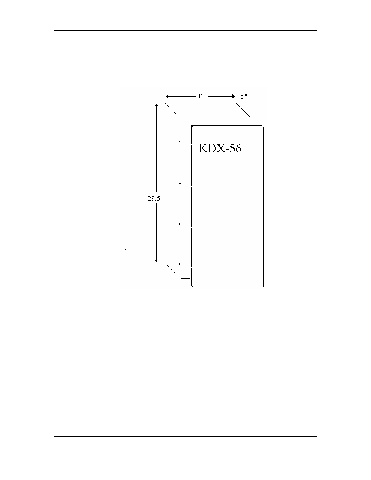
Equipment Description
The system is housed in a conventional-cooled, metal enclosure with a removable front cover. (See
Figure 1) The cover is held in place with #2 Philips head screws. The cabinet mounting dimensions are
12 inches wide, 29.5 inches high and 5 inches deep. A fully equipped cabinet weighs approximately 30
lbs.
Metal Brackets are used to attach the cabinet to a vertical surface. They are attached to the back of the
cabinet and positioned to extend above the top of the cabinet for access to keyhole slots for mounting
screws.
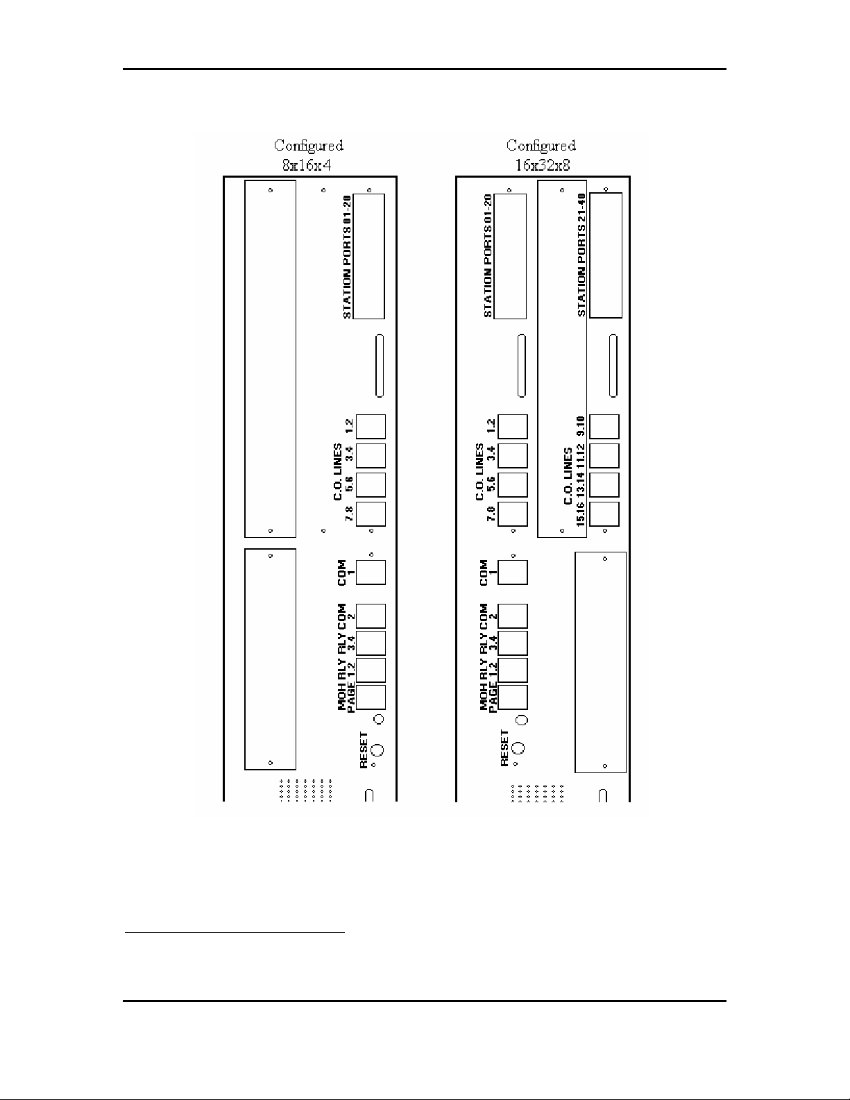
Connections to the system are made on the right side of the cabinet (See Figure 2).
Atlas System 56 Introduction and Programming - 8 -
Page 10

Atlas System 56 Introduction and Programming
a) Trunks are connected through card-edge-mounted, 4-pin jacks. Each jack connects 2 Trunks.
b) Stations are connected through card-edge-mounted, 50-pin Amphenol connectors. Each Amphenol
connects 20 stations (16-Digital and 4-SLP’s).
c) The power cord connects at the power receptacle located at the bottom of the cabinet.
d) The ground wire connects to a ground lug located at the bottom of the cabinet.
e) The Battery backup cables connect inside the KSU at the +Battery- terminals located on the power
supply card.
f) The external music sources and external page output connects through a card-edge mounted, 6-pin
jack.
g) The relays connect through card-edge-mounted, 6-pin jacks. Each jack connects 2 relays.
h) The serial ports connect through card-edge-mounted, 6-pin jacks. Each jack contains 1 serial port.
Atlas System 56 Introduction and Programming - 9 -
Page 11
Atlas System 56 Introduction and Programming
FIGURE 1:
Atlas System 56 Introduction and Programming - 10 -
Page 12
Atlas System 56 Introduction and Programming
IGURE 2:
F
CABINET
SIDE
PANEL CONNECTORS AND INDICATORS
ATLAS-56 Main MCB Card
Atlas System 56 Introduction and Programming - 11 -
Page 13

Atlas System 56 Introduction and Programming
The Main KSU provides for many connections to external devices as well as for the stations and
Trunks.
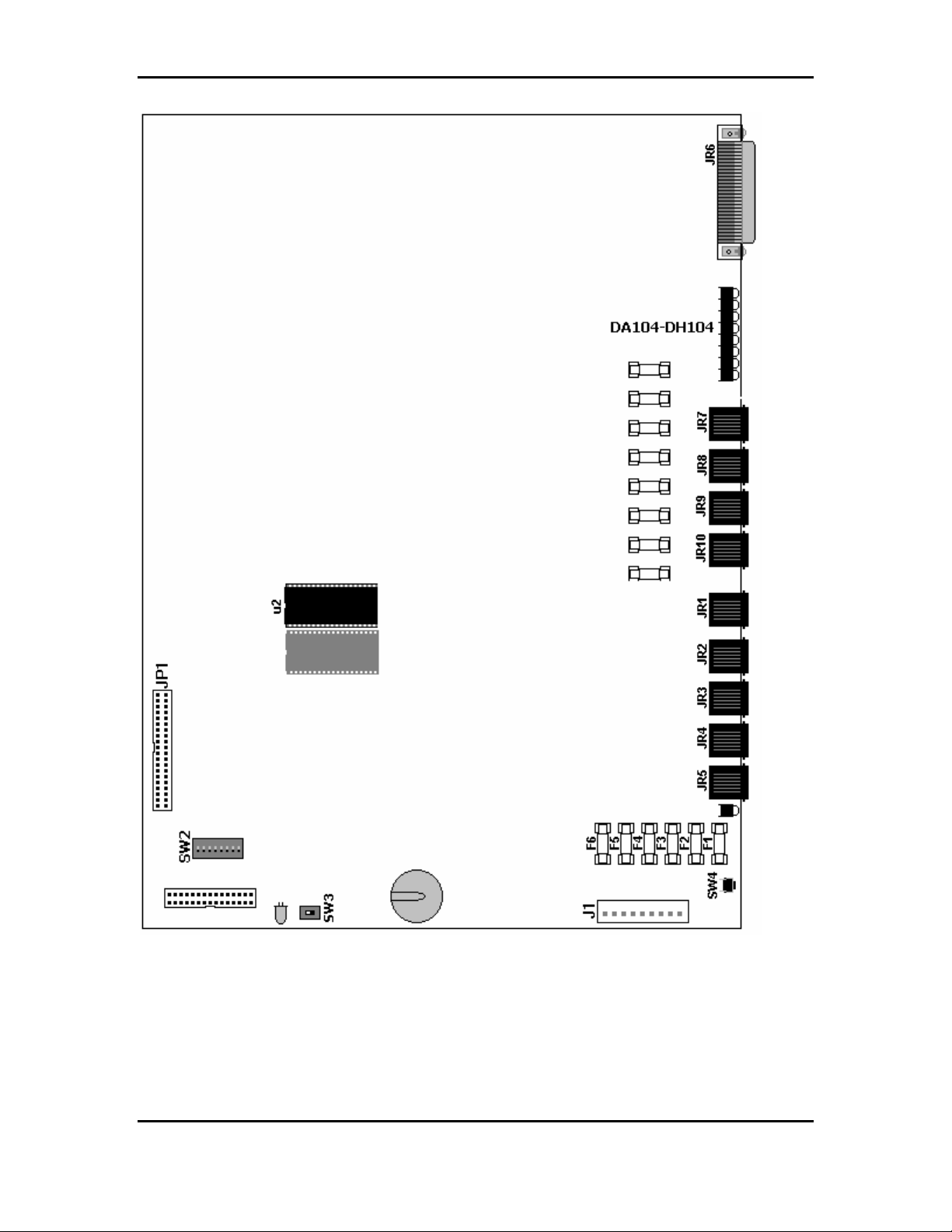
Connectors Description
JR1
JR2
JR3
JR4
JR5
JR6
JR7
JR8
JR9
JR10
J1
JP1
Serial Port 1 used for SMDR / PC Programming
Serial Port 2 used for Voice Mail Integration
Relay Interface 3 & 4 (Programmable)
Relay Interface 1 & 2 (Programmable)
External Page & Music Source 1 & 2 Interface
Digital Stations Ports 1 – 16 Single Line Ports 17 - 20
Trunk 1 & 2 RJ14 Interface
Trunk 3 & 4 RJ14 Interface
Trunk 5 & 6 RJ14 Interface
Trunk 7 & 8 RJ14 Interface
9-Pin Connector to Power Supply
Connector for 8x16x4 Expansion Card
Fuses Description
F1
F2
F3
F4
F5
F6
FA-H100
Atlas System 56 Introduction and Programming - 12 -
Protects External Page Port
Protects MOH Source 1
Protects MOH Source 2
Protects Digital Station Ports
Protects Single Line Ports
Protects Trunk Ports
Trunk Fuses – FA100=Trunk 1, FB100=Trunk 2…
Page 14
Atlas System 56 Introduction and Programming
Switches Description
SW2 Dip 1
SW2 Dip 2
SW2 Dip 3
SW2 Dip 4
SW2 Dip 5
SW2 Dip 6
SW2 Dip 7
SW2 Dip 8
Not Used
Not Used
Not Used
Not Used
Not Used
“ON” = 3 Digit ICM numbering / “OFF” = 2 Digit ICM numbering
Not Used
Not Used
Switches Description
SW3
SW4
Memory Back up Switch
System Reset Switch
LED Description
D2 Memory Back-up Battery “ON” Indicator
D3 CPU Status (Steady Flash indicates normal operation)
DA-H100 Trunk busy Status DA100=Trunk 1,DB100=Trunk 2…
See Figure 3 for connector, fuse, switches & LED locations.
Atlas System 56 Introduction and Programming - 13 -
Page 15
Atlas System 56 Introduction and Programming
FIGURE 3: ATLAS-56 MAIN MCB UNIT
Hardware Options
Atlas System 56 Introduction and Programming - 14 -
Page 16

Atlas System 56 Introduction and Programming
Backup Battery
The system power supply supports a backup battery package rated at 24 volts, 0.7 amperes/hour. A
trickle-charge maintains the battery at 95% efficiency, applies system cutover to battery when facility
power is removed, and provides system shutdown when battery power falls below a specified level.
External Music
Up to two (customer supplied) monaural music sources can be connected at the optional equipment
jack (JR5) located on the left side of the KSU. The connected music is available to the system only if
programmed using system Programming (PROG. 1-37 and 2-75) the impedance of the music source
must be 32ohms with power at approximately 100 milliwatts.
Note: An internal music source is available and is selected through system programming by default.
Note: In some circumstances there may be broadcast restrictions associated with the external music
source. Check with the sources original distributor and/or the radio station for copyright and
broadcast restrictions concerning background music and music–on-hold.
External Paging
The system supports a customer supplied amplifier for paging access to a single paging zone. The
amplifier can be connected at the optional equipment jack (JR5) located on the left side of the KSU.
Access is provided for 8 paging zones. The output for zones 1-7 must be connected through station
ports and must be assigned by system programming (PROG.3-35).
External Relays
The system supports 4 external relays for multiple functions such as station, trunk, loud-bell, Paging,
Music, and Door strike control. The customer supplied optional equipment can be connected at the
optional equipment jacks (JR3 & 4) located on the left side of the KSU. The contacts can be
programmed (PROG.3-40 and 3-41) for normally “open” or “closed” depending on customer needs.
Caller I.D.
(Future Feature)
The system supports a Caller I.D. module that offers Name or Number display. The Caller I.D module
connects inside the KSU to the connector marked ___. The caller I.D feature is programmed in the
system database (PROG.1-05, 2-26 and 2-73). Caller I.D. number is reported to SMDR print-out (see
figure 6).
Atlas System 56 Introduction and Programming - 15 -
Page 17

Atlas System 56 Introduction and Programming
Figure 4: Optional Equipment Jack Pin Functions
Atlas System 56 Introduction and Programming - 16 -
Page 18

Atlas System 56 Introduction and Programming
Serial Ports
The system supports 2 serial ports used for PC programming, SMDR (see figure.6) and WAV Voice
mail integration. They are card-edge-mounted modular jacks located on the left side of the cabinet.
They are labeled JR1 and JR2. The distance between the data device and the common equipment can
be up to 100 feet in a quiet electrical environment. Shielded cable may be required for some runs. For
longer distances, a customer supplied serial extender may be used to relay the data communications
between the common equipment and the data devices.
Baud rate = 2400bps; data bits = 8; stop bits = 1; parity = none.
Figure 5: Serial Port Jack Pin Functions
Atlas System 56 Introduction and Programming - 17 -
Page 19

Atlas System 56 Introduction and Programming
SMDR Printout
ST TK TELEPHONE NO. ACC.NO. DATE START DURATION RING
C.L.I.D.
10 05 5156310 T 04/01 09:15 00:01:05
16 04 15618400636 04/01 09:18 00:04:56
26 01 ******************* 04/01 10:02 00:14:30 00:06
5615156300
****02 ******************* 04/01 10:03 00:54
5615156301
12 09 1305551212 254 04/01 10:18 00:04:18
17 <STATION ALARM> 04/01 13:00
COLUMN CONTENT EXPLANATION
1 ST SATION NUMBER
2 TK TRUNK NUMBER
3
4 “T” ENTRY DENOTES A TRANSFERRED CALL
5 ACC.NO. OPTIONAL CALLER DIALED ACCOUNT CODE
6 DATE DATE OF THE CALL RECORD- MM:DD
7 START TIME OF DAY CALL STARTED- HH:MM
8 DURATION LENGTH OF CALL- HH:MM:SS
9 RING RINGING TIME FOR INCOMING CALLS- MM:SS
10 C.L.I.D. CALLING PARTIES TELEPHONE NUMBER
TELEPHONE
NO.
TELEPHONE NUMBER CALLED. *REPRESENTS AN INCOMING
CALL. STATION ALRMS ARE ALSO NOTED HERE.
Explanation of Example Entries:
1. On 04/01 at 09:15 AM Station 10 seized trunk 5 and made an outside call to 5156310. The
call lasted for 1 minute and 5 seconds. Before being transferred.
2. On 04/01 at 09:18 AM Station 16 seized trunk 4 and made an outside call to 15618400636.
The call lasted for 4 minutes and 56 seconds.
3. An incoming call rang on trunk 1 for 6 seconds from 5615156300 was answered by station
26. The call lasted 14 minutes and 30 seconds.
4. An incoming call rang on trunk 2 for 58 seconds from 5615156301 and went unanswered.
5. An outgoing call to 13055551212 on trunk 9 by station 12 lasted 4 minutes and 18 seconds
during which time the station user entered an Account code 254.
6. At 1:00 PM a station alarm rang at Station 17.
F
IGURE 6: SMDR CALL RECORDS AND EXPLANATIONS
Installation Procedures
Atlas System 56 Introduction and Programming - 18 -
Page 20

Atlas System 56 Introduction and Programming
This part contains the procedures for installing the ATLAS-56 Digital Business System. Precautions
for personnel and equipment safety and installation prerequisites are provided before detailed
instructions for installing the equipment cabinet, connecting ground, installing and wiring station
cross-connect blocks, connecting Trunk lines, and installing station equipment.
Precautions
The following paragraphs explain the precautions to be observed for handling, installing, and working
with system equipment and components.
Handling Static-Sensitive Devices
WARNING: The system contains static-sensitive components. Personnel who
are required to handle Printed Board Assemblies (PBA’s), components, or
wiring must have knowledge of proper handling techniques.
The human body can easily accumulate a high voltage charge of static electricity. Precautions must be
taken to prevent this charge from damaging static-sensitive components. The following are standard
handling precautions for static sensitive devices:
Touch the cabinet to dissipate any stored charge immediately before removing, inserting, or otherwise
handling a PBA.
Hold the PBA by its edges and avoid touching component pins or connectors.
Cover work surfaces with conductive material connected to earth ground. A ground clip connected to a
static-protective shipping bag provides an adequately protective work surface.
Use flexible ground straps to continuously discharge static electricity.
Store PBA’s in static-protective shipping bags.
Installing Station Wiring
DANGER: TO REDUCE RISK OF ELECTRICAL SHOCK AND PERSONAL
INJURY, USE CARE WHEN INSTALLING STATION WIRING.
Observe the following precautions when installing station wiring:
Never install telephone wiring during a lightning storm.
Never install telephone jacks in wet locations unless the jack is specifically designed for wet
environments.
Never touch un-insulated telephone wire or terminals unless the telephone line has been disconnected
at the network interface.
Use caution when installing or modifying telephone lines.
Atlas System 56 Introduction and Programming - 19 -
Page 21

Atlas System 56 Introduction and Programming
Connecting Power Cords
WARNING: Do not attach power supply cords to building surfaces.
The basic system is furnished with a detachable power supply cord that is
configured for connecting to a branch circuit receptacle equipped with a
third wire ground. The cord should be dressed for appearance and safety,
but never attached to the building surface.
Site Requirements
The selection of a suitable location is essential when installing the key service unit (KSU). The area
should be clean, dry, static-free, temperature controlled, and accessible only to authorized personnel.
When selecting a site, give careful consideration to the following:
Ample space must be allowed to mount the cabinet and MDF (Main
Distribution Frame) and to allow for removal of the KSU cover to access
assemblies and cards within the cabinet.
A well-ventilated and well-lighted area with a temperature range of 32-100°
F (0-40° C) and 10%-90% relative non-condensing humidity. The area must
not be exposed to direct sunlight, heat or dust. Optimal temperature range
is 40-70° F.
A dedicated 110/220 Volt AC, 15 Amp, 50/60 Hz, single phase, 3 wire, and
parallel blade with ground power outlet should be located within 6 feet of the
KSU. Additional outlets for music source, paging amplifier, etc. as needed.
The AC receptacles must be third-wire grounding type. The third-wire
ground must be connected to an approved earth ground through the singlepoint grounding circuit at the power distribution panel.
Avoid areas that produce radio frequency interference (RFI) or electromagnetic interference (EMI). (E.g. electric welding equipment, radio
frequency transmitters, magnets, refrigerators, copy machines, microwave
ovens, etc.)
Locate the KSU and stations so as to minimize cable length. All station
cables must be 2-pair twisted-pair cable and must be home run. The Digital
Keyphone may be wired differently.
Cabling lengths must not exceed the following:
Digital phone: 24 gauge 600-3000 feet depending upon wiring configuration.
(See Fig. 22)
Atlas System 56 Introduction and Programming - 20 -
Page 22

Atlas System 56 Introduction and Programming
Single-Line Telephones: 800 ohms using 24 gauge – 5000 feet
The Trunk lines connect to the system through modular jacks located on the left side of the KSU.
Central Office terminations should be within 6 feet of the cabinet/main distribution frame.
Make sure there is a good earth ground utilizing #12 AWG or larger standard, copper wire within 25
feet of the KSU. A metallic COLD water pipe usually provides a reliable ground path. Carefully
check that the pipe does not contain insulated joints that could isolate the ground. (The pipe must be
metallic from the point of ground to the connection to the water main outside the building).
Warning: To avoid equipment damage, do not attempt to connect or operate the equipment before
proper ground has been installed.
Power Surge Protector Ground
Power surge protectors must be grounded either to the approved earth ground or an equally adequate
but separate grounding system. Install ground wires of the size specified by the manufacturer between
the line protector devices and the earth ground connection. Be sure to connect the ground wire at a
point closer to true earth ground than the AC distribution panel single-point ground wire and the
chassis ground wire connections. Secure the attaching clamp.
Telephone Line Power Surge Protection
System equipment must be protected against power surges on all externally connected telephone lines.
This includes protecting lines coming into the building from the telephone company, lines going out of
the building to off-premises stations located in an adjacent building, and lines going into the adjacent
building that houses the off-premises stations.
Cable Construction
Atlas System 56 Introduction and Programming - 21 -
Page 23
Atlas System 56 Introduction and Programming
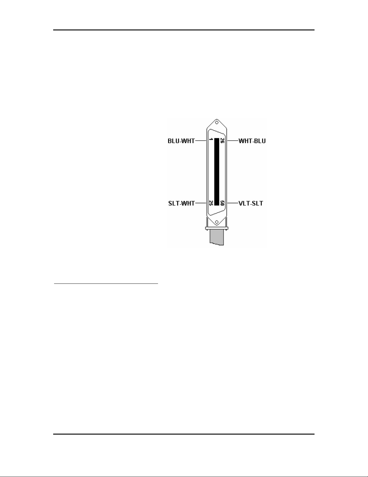
One 25-pair cable is required for each system card installed. The cables connect station interface
circuits on the 50-pin connectors to the station cross connect blocks on the MDF. Construct each cable
with one end terminated in an Amphenol-type, male connector. To allow proper routing of the cable
during installation, pin 1 must be at the top, opposite the cable-entry end of the connector. (See Figure
7) Terminate the opposite end of the cable as dictated by the type cross-connect block used.
Note: Consider cable routing before the cable to the correct length.
FIGURE 7: PIN ARRANGEMENT – 50-PIN CABLE CONNECTOR
Unpacking and Inspecting
The following paragraphs provide directions for unpacking and inspecting the system components.
WARNING: The system equipment contains static sensitive components. Personnel who are required
to handle components or wiring must have knowledge of proper handling techniques and must have
the necessary safeguard equipment for protecting static-sensitive devices. Refer to PRECAUTIONS.
All equipment is packaged in corrugated cardboard containers. All equipment options are packaged
separately in individual cartons. Each telephone is packaged separately in an individual carton.
However, an outer slip or larger container may be used to group quantities of telephones.
Check all items received against the packing slip. Examine cartons for visual signs of damage. If
cartons appear too be damaged, make a note of such damage on the packing slip and on the carrier way
bill, if available.
Atlas System 56 Introduction and Programming - 22 -
Page 24

Atlas System 56 Introduction and Programming
Open the carton containing the system equipment. Remove the packaging material from the carton.
Remove the cabinet and lay it face–up on a level work surface. Remove all packaging material. Check
the exterior cabinet. Make a note of any damages.
Observing electronics equipment handling precautions, remove each piece of equipment from its
shipping container. As each item is unpacked, place it on a level work surface. Remove packaging
material and inspect the equipment for physical damage. Make a note of any damages.
Report all damages noted to your supplier.
Cabinet Installation
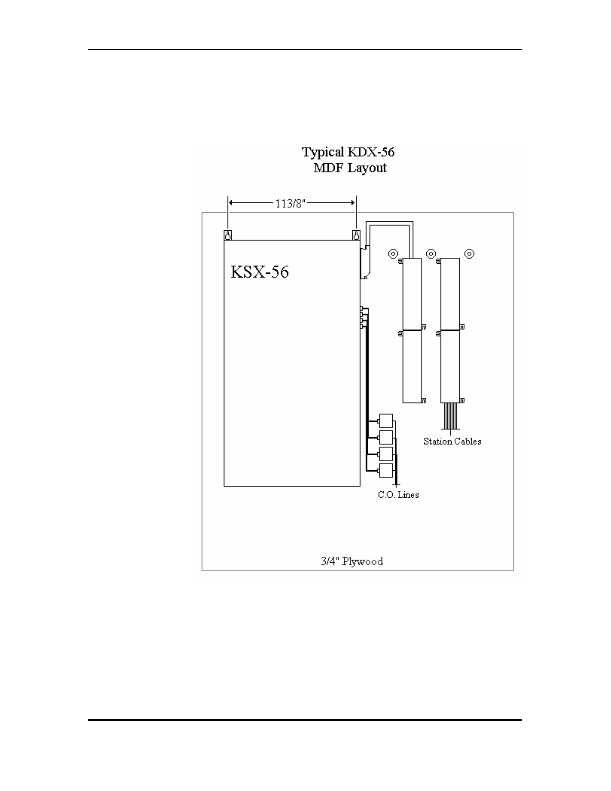
Mount the cabinet so that all cables and power cord are neatly arranged. Do not mount the cabinet
directly on masonry, concrete, or other wall surfaces subject to moisture or condensation. When wall
mounting, a ¾” thick plywood backboard should be attached to the equipment room wall for
mounting the cabinet and associated equipment. The backboard should be large enough to
allow sufficient space for the MDF connecting blocks and optional equipment to be mounted and
serviced conveniently.
Locate the two mounting hardware screws 113/8” a part on-center and assure a minimum of 3” above
any obstruction. (See Figure 8).
Atlas System 56 Introduction and Programming - 23 -
Page 25
Atlas System 56 Introduction and Programming
FIGURE 8: ATLAS-56 MOUNTING & MDF LAYOUT
Atlas System 56 Introduction and Programming - 24 -
Page 26
Atlas System 56 Introduction and Programming
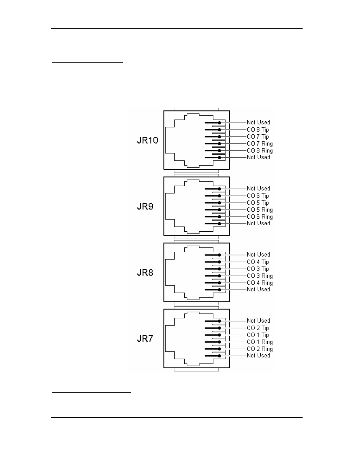
Trunk Connections
All trunk connections are made on the left side of the cabinet. (See Figure 2) Two lines are connected
through each modular jack. Refer to Figure 9 for modular jack pin functions. Install a modular line
cord between each trunk terminating modular wall jack and the corresponding jack on the side of the
cabinet.
Figure 9: Typical Trunk Connecting Jack Pin Functions
Station Connections
Atlas System 56 Introduction and Programming - 25 -
Page 27

Atlas System 56 Introduction and Programming
All stations connect to the system through the 50-pin connector(s) located on the right side of the
cabinet using 25-pair cables and 50-pin MDF cross-connect blocks. Tables B & C show the MDF
cable wiring arrangement including standard wiring color, system signal designations, and the
corresponding cross-connect block terminals.
To install and wire a station cross-connect block, proceed as follows:
a) Install the cross-connect blocks to the right side of the cabinet allowing sufficient room to
access both sides of each block.
b) Locate one of the previously constructed 25-pair cables (refer to Cable Construction).
c) Plug the cable connector into the correct 50-pin connector on the right side of the cabinet.
d) Route the cable up the side of the cabinet, to the right, and down through the center of the
cross-connect blocks to the correct block. Dress and secure the cable at several points, and
then punch down the leads using the standard color code.
Station Wiring
Twisted pair station cable is required for operation of Digital keyphones. Therefore, it is recommended
that 3-pair, #24 AWG station cable be used throughout the system. This allows changes and additions
to the system without re-wiring, and minimizes potential problems with telephones connected to the
wrong type station cable.
Cable conductor connections at the modular telephone jacks are identical for all station equipment.
(See Figure 9). Although conductor functions may differ, wiring connections must stay consistent. Use
4-terminal, modular wall jacks at all stations.
The following guidelines should be observed when running station cable:
a) AVOID cable runs parallel to light fixtures or AC lines not in conduit. If unavoidable, run the
cables across them at right angles.
b) DO NOT run station cables inside electrical conduit already occupied by AC power cable.
c) DO NOT run station cables near equipment with electrical motors or past strong magnetic
fields (copy machines, heavy motors, welding equipment, ECT…).
d) DO not place station cables where they can be stepped on or rolled over by office chairs.
TABLE B: ATLAS-56 MAIN JR6 CONNECTIONS
Atlas System 56 Introduction and Programming - 26 -
Page 28

Atlas System 56 Introduction and Programming
25-PAIR CONNECTING STATION LINE
CABLE BLOCK CABLE CORD CIRCUIT
PIN COLOR
CODE
26
WHT-BLU
1
BLU-WHT
27
WHT-ORG
2
ORG-WHT
28
WHT-GRN
3
GRN-WHT
29
WHT-BRN
4
BRN-WHT
30
WHT-SLT
5
SLT-WHT
31
RED-BLU
6
BLU-RED
32
RED-ORG
7
ORG-RED
33
RED-GRN
8
GRN-RED
34
RED-BRN
9
BRN-RED
35
RED-SLT
10
SLT-RED
36
BLK-BLU
11
BLU-BLK
37
BLK-ORG
12
ORG-BLK
38
BLK-GRN
13
GRN-BLK
39
BLK-BRN
14
BRN-BLK
40
BLK-SLT
15
SLT-BLK
41
YEL-BLU
16
BLU-YEL
42
YEL-ORG
17
ORG-YEL
43
YEL-GRN
18
GRN-YEL
TERM FUNCTION 2-PR.
CABLE
1
2
3
4
5
6
7
8
9
10
11
12
13
14
15
16
17
18
19
20
21
22
23
24
25
26
27
28
29
30
31
32
33
34
35
36
TX+
TX-
RX+
RX-
TX+
TX-
RX+
RX-
TX+
TX-
RX+
RX-
TX+
TX-
RX+
RX-
TX+
TX-
RX+
RX-
TX+
TX-
RX+
RX-
TX+
TX-
RX+
RX-
TX+
TX-
RX+
RX-
TIP
RING
WHT-BLU
BLU-WHT
WHT-ORG
ORG-WHT
WHT-BLU
BLU-WHT
WHT-ORG
ORG-WHT
WHT-BLU
BLU-WHT
WHT-ORG
ORG-WHT
WHT-BLU
BLU-WHT
WHT-ORG
ORG-WHT
WHT-BLU
BLU-WHT
WHT-ORG
ORG-WHT
WHT-BLU
BLU-WHT
WHT-ORG
ORG-WHT
WHT-BLU
BLU-WHT
WHT-ORG
ORG-WHT
WHT-BLU
BLU-WHT
WHT-ORG
ORG-WHT
WHT-BLU
BLU-WHT
TEL B1
CHANNEL
GRN
STATION
10/100
RED
(PORT 01)
BLK
(Dip 3,4 “ON”)
YEL
GRN
STATION
12/102
RED
(PORT 03)
BLK
YEL
GRN
STATION
14/104
RED
(PORT 05)
BLK
YEL
GRN
STATION
16/106
RED
(PORT 07)
BLK
YEL
GRN
STATION
18/108
RED
(PORT 09)
BLK
YEL
GRN
STATION
20/110
RED
(PORT 11)
BLK
YEL
GRN
STATION
22/112
RED
(PORT 13)
BLK
YEL
GRN
STATION
24/114
RED
(PORT 15)
BLK
YEL
GRN
SLP STATION
26/116
RED
(PORT 17)
B2
CHANNEL
STATION
11/101
(PORT 02)
(Dip 1,2 “ON”)
STATION
13/103
(PORT 04)
STATION
15/105
(PORT 06)
STATION
17/107
(PORT 08)
STATION
19/109
(PORT 10)
STATION
21/111
(PORT 12)
STATION
23/113
(PORT 14)
STATION
25/115
(PORT 16)
N/A
Atlas System 56 Introduction and Programming - 27 -
Page 29

Atlas System 56 Introduction and Programming
44
19
45
20
46
21
47
22
48
23
49
24
YEL-BRN
BRN-YEL
YEL-SLT
SLT-YEL
VLT-BLU
BLU-VLT
VLT-ORG
ORG-VLT
VLT-GRN
GRN-VLT
VLT-BRN
BRN-VLT
37
38
39
40
41
42
43
44
45
46
47
48
TIP
RING
TIP
RING
TIP
RING
WHT-BLU
BLU-WHT
WHT-BLU
BLU-WHT
WHT-BLU
BLU-WHT
GRN
RED
GRN
RED
GRN
RED
SLP STATION
27/117
(PORT 18)
SLP STATION
28/118
(PORT 19)
SLP STATION
29/119
(PORT 20)
N/A
N/A
N/A
TABLE C: ATLAS-56 EXPANSION JR CONNECTIONS
25-PAIR CONNECTING STATION LINE
CABLE BLOCK CABLE CORD CIRCUIT
PIN COLOR
CODE
26
WHT-BLU
1
BLU-WHT
27
WHT-ORG
2
ORG-WHT
28
WHT-GRN
3
GRN-WHT
29
WHT-BRN
4
BRN-WHT
30
WHT-SLT
5
SLT-WHT
31
RED-BLU
6
BLU-RED
32
RED-ORG
7
ORG-RED
33
RED-GRN
8
GRN-RED
34
RED-BRN
9
BRN-RED
35
RED-SLT
10
SLT-RED
36 BLK-BLU 21 TX+ WHT-BLU GRN STATION STATION
TERM FUNCTION 2-PR.
CABLE
1
2
3
4
5
6
7
8
9
10
11
12
13
14
15
16
17
18
19
20
TX+
TX-
RX+
RX-
TX+
TX-
RX+
RX-
TX+
TX-
RX+
RX-
TX+
TX-
RX+
RX-
TX+
TX-
RX+
RX-
WHT-BLU
BLU-WHT
WHT-ORG
ORG-WHT
WHT-BLU
BLU-WHT
WHT-ORG
ORG-WHT
WHT-BLU
BLU-WHT
WHT-ORG
ORG-WHT
WHT-BLU
BLU-WHT
WHT-ORG
ORG-WHT
WHT-BLU
BLU-WHT
WHT-ORG
ORG-WHT
TEL B1
CHANNEL
GRN
STATION
30/120
RED
(PORT 21)
BLK
YEL
GRN
STATION
32/122
RED
(PORT 23)
BLK
YEL
GRN
STATION
34/124
RED
(PORT 25)
BLK
YEL
GRN
STATION
36/126
RED
(PORT 27)
BLK
YEL
GRN
STATION
38/128
RED
(PORT 29)
BLK
YEL
B2
CHANNEL
STATION
31/121
(PORT 22)
STATION
33/123
(PORT 24)
STATION
35/125
(PORT 26)
STATION
37/127
(PORT 28)
STATION
39/129
(PORT 30)
Atlas System 56 Introduction and Programming - 28 -
Page 30

Atlas System 56 Introduction and Programming
11
37
12
38
13
39
14
40
15
41
16
42
17
43
18
44
19
45
20
46
21
47
22
48
23
49
24
BLU-BLK
BLK-ORG
ORG-BLK
BLK-GRN
GRN-BLK
BLK-BRN
BRN-BLK
BLK-SLT
SLT-BLK
YEL-BLU
BLU-YEL
YEL-ORG
ORG-YEL
YEL-GRN
GRN-YEL
YEL-BRN
BRN-YEL
YEL-SLT
SLT-YEL
VLT-BLU
BLU-VLT
VLT-ORG
ORG-VLT
VLT-GRN
GRN-VLT
VLT-BRN
BRN-VLT
22
23
24
25
26
27
28
29
30
31
32
33
34
35
36
37
38
39
40
41
42
43
44
45
46
47
48
TX-
RX+
RX-
TX+
TX-
RX+
RX-
TX+
TX-
RX+
RX-
TIP
RING
TIP
RING
TIP
RING
TIP
RING
BLU-WHT
WHT-ORG
ORG-WHT
WHT-BLU
BLU-WHT
WHT-ORG
ORG-WHT
WHT-BLU
BLU-WHT
WHT-ORG
ORG-WHT
WHT-BLU
BLU-WHT
WHT-BLU
BLU-WHT
WHT-BLU
BLU-WHT
WHT-BLU
BLU-WHT
RED
BLK
YEL
GRN
RED
BLK
YEL
GRN
RED
BLK
YEL
GRN
RED
GRN
RED
GRN
RED
GRN
RED
40/130
(PORT 31)
STATION
42/132
(PORT 33)
STATION
44/134
(PORT 35)
SLP STATION
46/136
(PORT 37)
SLP STATION
47/137
(PORT 38)
SLP STATION
48/138
(PORT 39)
SLP STATION
49/139
(PORT 40)
41/131
(PORT 32)
STATION
43/133
(PORT 34)
STATION
45/135
(PORT 36)
N/A
N/A
N/A
N/A
Each Digital Phone is supplied with a modular line cord. A 625A type jack assembly or equivalent should
be mounted where each telephone is to be installed. Cable pairs should not be crossed or reversed during
installation (See Figure. 10). Correct polarity must be maintained for correct operation of Digital phones.
Atlas System 56 Introduction and Programming - 29 -
Page 31

Atlas System 56 Introduction and Programming
FIGURE 10: STATION JACK WIRING
All station connections are made through the amphenol(s) located on the upper right side of the KSU.
The Main amphenol (Ext.’s 10 – 29) is labeled JR6. The expansion amphenol (if equipped) is labeled
(See Fig. 14).
Each Amphenol connector provides for 16 digital ports (8 - 2B+D channels) and 4 single line ports.
Digital Phone Dip Switch Settings
The 16 Digital ports are wired to the first 8 circuits of the amphenol. Each of the first 8 circuits on this
card are 2B+D, each B channel can support 1 Digital Keyphone. The phones are connected / wired in
parallel. Remove the desk/wall mount adapter from the base of the Digital Keyphone. This will reveal
4 dipswitches. The phone with the switches set: 1, 2 OFF / 3, 4 ON will be the odd numbered port
(B1 channel) and the phone with the switches set: 1, 2 ON / 3, 4 OFF will be the even numbered port
Atlas System 56 Introduction and Programming - 30 -
Page 32

Atlas System 56 Introduction and Programming
(B2 channel). Both B1 and B2 channels are connected to the white/blue and white/orange pair (2 pair
connection). The phones are wired in parallel but there are some limitations that must be observed.
(See Fig. 11)
Examples:
1) A single Digital Keyphone can be connected to a cable run up to 3000’ in length.
2) Cable runs up to 1500’ can be terminated in two parallel runs (2 pair) up to a maximum of
50’. One phone uses the B1 channel (1, 2 OFF / 3, 4 ON). The other phone uses the B2
channel (1, 2 ON / 3, 4 OFF).
3) 2 parallel cables (2 pair) can be run a maximum of 600’ from the MDF but the difference in
length between the two cables cannot exceed 50’.
4) LD-40 model phones must always use the B1 channel. When using an LD40 on the B1
channel, a DT36 button phone can be used in parallel only when set for the B2 channel.
The Main and Expansion are equipped with 25 pair female type amphenol connectors. The installer
should run 25 pair cables with male amphenol connectors from his own MDF (e.g.: 66 type block).
DSS Installation
The DSS unit requires a digital phone port just as the digital phone does. Observe Dipswitch settings
on bottom of DSS.
The DSS is always installed in the next highest physical digital phone port from the phone that will
work with it. (E.g. Digital phone port11 B1 channel / DSS must be port 12 B2 channel.
It is possible to install more than one DSS with one digital phone. (E.g. Digital phone port 23 B1
channel / DSS (1) must be port 24 B2 channel, DSS (2) must be port 25 B1 channel)
Atlas System 56 Introduction and Programming - 31 -
Page 33

Atlas System 56 Introduction and Programming
FIGURE 11: DIGITAL PHONE CABLE LENGTH
To Wall Mount a DT36 Digital phone
♦ Remove the base stand from the bottom of the digital phone. (See Fig. 10). Press in on the
large wedge to disengage it from the housing.
♦ Position the base stand on the wall where the digital phone is to be located with the large
wedge down, and mark on the wall the location of the small opening in each of the two
keyhole slots.
♦ Install a #8 x ½ inch pan-head screw at each marked location. Partially tighten the screws
leaving approximately ¼ inch protruding.
Atlas System 56 Introduction and Programming - 32 -
Page 34

Atlas System 56 Introduction and Programming
♦ Reattach the base to the digital phone with the large wedge down.
♦ Position the digital phone with the base stand over the two mounting screws with the screws
inserted into the large slots in the keyholes.
♦ Slide the digital phone down until it is tight and stable.
♦ Lift and turn the handset cradle tab so the tab is up. (See Fig. 11)
♦ Place the handset on-hook and insure that the tab holds the handset stable.
FIGURE 12: WALL MOUNTING A DT-36 TELEPHONE
BATU UNIT
The BATU Unit provides the capability to connect external batteries to the
system to provide for complete system operation in the event of local
power failure. Attach batteries
(24 VDC) to the BATU Unit at the appropriate terminals. (See Fig.) The
system applies a trickle charge to the battery when it is not in use.
Keep the battery(s) dry and clean. Avoid damp wet areas or areas where
the battery may be easily damaged. Wires should run from the battery(s)
to the terminals on the BATU Unit. When connecting to the BATU, pay
particular attention to matching the positive and negative connections.
Atlas System 56 Introduction and Programming - 33 -
Page 35

Atlas System 56 Introduction and Programming
Improper connection will damage the power supply. When operating from
the battery, the system will automatically cut off the power supply from the
battery when the voltage gets too low, so that the battery can be
recharged.
CAUTION!!!! To reduce the risk of fire or injury please note the
following:
Do not dispose of the battery(s) in a fire. The cell may explode.
Check with local codes for special disposal instructions.
Do not open or mutilate the battery(s). Released electrolyte is
corrosive and may cause damage to the eyes or skin. It may be
toxic if swallowed.
Exercise care in handling the battery(s) in order not to short the
battery with conducting materials such as rings, bracelets and keys.
The battery may overheat and cause burns.
Observe proper polarity orientation between the battery(s) and
BATU Unit.
Do not mix battery(s) of different sizes or from different
manufacturers in this product.
The length of time system operation is maintained under battery power
depends on battery capacity. Typical system support for the 24 Volt
battery(s) is approximately one hour.
INTERFACE CARDS
Expansion Card
FUTURE INTERFACE DEVICES
Atlas System 56 Introduction and Programming - 34 -
Page 36

Atlas System 56 Introduction and Programming
T-1 Trunk / PRI Card
BRI Card
DID / Caller ID Card
C.O. Line (TRUNK) CONNECTIONS
Connections (Central Office / PBX) to the ATLAS-56 are made directly at the right side of the KSU
where 4 - RJ14 connectors are mounted. (See Fig. 11) Using a standard 4 conductor modular cord the
trunks are connected as follows:
RJ14 Trunks Description
JR7 1 INNER PAIR (RED &GREEN)
JR7 2 OUTER PAIR (BLACK & YELLOW)
JR8 3 INNER PAIR (RED &GREEN)
JR8 4 OUTER PAIR (BLACK & YELLOW)
JR9 5 INNER PAIR (RED &GREEN)
JR9 6 OUTER PAIR (BLACK & YELLOW)
JR10 7 INNER PAIR (RED &GREEN)
JR10 8 OUTER PAIR (BLACK & YELLOW)
The system allows for a maximum of 16 Trunks. Trunks 1-8 are on the Main MCB Unit, Trunks 9-16 are
on the Expansion Card.
EXPANSION Card
The Expansion card is mounted on top of the Main MCB. First remove the cover of the Main KSU.
Then place the expansion card on top of the Main card. (See Fig. 15)
Fig. 15
Atlas System 56 Introduction and Programming - 35 -
Page 37

Atlas System 56 Introduction and Programming
MEMORY BACKUP SWITCH
♦ The memory backup switch (SW3) is located on the bottom left side of the Main-MCB (See
Fig.)
Turning this switch ON will insure that the KSU will retain all stored programming in the
event of a power outage.
♦ ONCE THE SYSTEM IS INSTALLED, SET THE MEMORY BACKUP SWITCH TO
THE ON POSITION to prevent the loss of stored information.
♦ When the Memory Back-up switch is ON, the LED on the Main-MCB (LED D2) will be lit.
Atlas System 56 Introduction and Programming - 36 -
Page 38

Atlas System 56 Introduction and Programming
0
1
4
8
D
D
2
4
5
0
2
3
IGURE 1: ............................................................................................................................................................................................1
F
FIGURE 2: CABINET SIDE PANEL CONNECTORS AND INDICATORS .......................................................................................................1
FIGURE 3: ATLAS-56 MAIN MCB UNIT.............................................................................................................................................1
FIGURE 4: SMDR CALL RECORDS AND EXPLANATIONS .....................................................................................................................1
FIGURE 5: OPTIONAL EQUIPMENT JACK PIN FUNCTIONS ...............................................................ERROR! BOOKMARK NOT DEFINE
FIGURE 6: SERIAL PORT JACK PIN FUNCTIONS ..............................................................................ERROR! BOOKMARK NOT DEFINE
FIGURE 7: PIN ARRANGEMENT – 50-PIN CABLE CONNECTOR .............................................................................................................2
FIGURE 8: ............................................................................................................................................................................................2
FIGURE 9: TYPICAL TRUNK CONNECTING JACK PIN FUNCTIONS.........................................................................................................2
FIGURE 10: STATION JACK WIRING.....................................................................................................................................................3
FIGURE 11: DIGITAL PHONE CABLE LENGTH .......................................................................................................................................3
FIGURE 12: WALL MOUNTING A DT-36 TELEPHONE ..........................................................................................................................3
Atlas System 56 Introduction and Programming - 37 -
Page 39

Atlas System 56 Introduction and Programming
NOTICE
The KDX-56 comes with two manuals. This manual contains a step-by-step explanation of the
installation process, with diagrams. The Programming Guide introduces the programming process by
which the system can be programmed through the Digital phones.
The procedures and methods provided in this manual have been prepared in a step-by-step manner to
assist the installer in planning and performing the installation task, system operation and feature operation.
The information contained in this document is believed to be correct and accurate in all respects. The
information contained in this document is subject to change without notice. Periodic changes may be made
to the information contained in this document without any obligation to notify any such persons of such
changes. No responsibility is assumed for any errors or omissions in this document.
The adjustments and settings mentioned in this manual should be carried out strictly by personnel who have
been trained for the operation of this equipment and have also received instructions in regard to the safe
handling of electrical equipment.
While this device is designed to be reasonably secure against intrusions from fraudulent callers, it is by no
means invulnerable to fraud. Therefore, no expressed or implied warranty is made against such fraud.
WHEN PROGRAMMING EMERGENCY NUMBERS AND (OR) MAKING TEST CALLS TO
EMERGENCY NUMBERS:
1. Remain on the line and briefly explain to the dispatcher the reason for the call.
2. Perform such activities in the off-peak hours; such as early morning or late evenings.
Protection of this equipment from hazardous voltages is the responsibility of the customer / owner of the
equipment.
Atlas System 56 Introduction and Programming - i -
Page 40

Atlas System 56 Introduction and Programming
KEY SYSTEM U.S. LIMITED WARRANTY
Key System US warrants to its authorized members and to the original retail customer of
a Key System US product, for a period of one year from the date of shipment of the
product from Key System US’s warehouse, that the “product”, except consumable items,
will be free from defects in material and workmanship when used in a normal and
common manner.
The sole obligation of Key System US under this warranty is at the sole option of Key
System US, the repair or replacement, with new or refurbished parts, of the defective or
missing parts that are causing the malfunction and which are determined to be defective
by Key System US.
Dealer or user shall be responsible to pay for shipment of the defective parts to Key
System US or Key System US’s authorized representative and for any and all expenses
connected with the removal and re-installation. In lieu of repair or replacement, Key
System US at its sole option and full satisfaction of its warranty obligations, refund the
price charged by Key System US to its members for such parts as are determined by Key
System US to be defective and which are returned to Key System US through an
authorized dealer within the warranty period and no later than 30 days after such
malfunction, whichever occurs first.
This warranty does not cover defects as arise from accidents, neglect, misuse, failure of
electric power, air conditioning, humidity control or causes beyond ordinary use. All
warranty claims shall be waived unless reported, in writing to Key System US prior to the
expiration of the applicable warranty period.
Key System US makes no other warranties, expressed or implied, and specifically
disclaims any implied warranty of merchantability or fitness for a particular purpose.
These warranties are dealer’s and user’s sole remedies and in lieu of all obligations or
liabilities on the part of Key System US for damages, including, but not limited to
special, incidental or consequential damages arising out of or in connection with the use
of the products, or any damages whatsoever resulting from loss of use, data or profits,
arising out of or in connection with the performance of the products. Whether in a
contract or tort action, including negligence, even if Key System US has been advised of
the possibility of such damages. The total maximum liability of Key System US for
breach of warranty shall be limited to a refund of the cost of the defective product.
No person other than an officer of Key System US may extend or modify this warranty,
and no modification or extension of this warranty shall be effective unless in writing
signed by the authorized officer of Key System US.
Atlas System 56 Introduction and Programming - ii -
Page 41

Atlas System 56 Introduction and Programming
TABLE OF CONTENTS
PROGRAMMING INTRODUCTION.............................. 2
Notice..................................................................................................................................................... 2
HARDWARE PROGRAMMING..................................... 3
Initial Setup........................................................................ 3
Memory Protection............................................................................................................................... 3
Load Default ......................................................................................................................................... 3
SOFTWARE PROGRAMMING...................................... 4
LCD Display phone.............................................................................................................................. 4
List of Terms Used............................................................................................................................... 4
Port and Station Numbering ........................................... 5
Trunk Numbering.............................................................. 5
Night Service - Day Mode and Night Mode Operation6
System Programming ...................................................... 6
Accessing Programming..................................................................................................................... 6
Entering Password............................................................................................................................... 7
Entering System Programming while on a Trunk Call.................................................................... 8
Selecting a Program Section.............................................................................................................. 8
Exiting from System Programming.................................................................................................... 9
Using Programming Keys................................................................................................................... 9
Saving a Change ................................................................................................................................. 9
Entering a Station Number instead of Port Number ..................................................................... 10
Getting a Busy Signal........................................................................................................................ 10
Atlas System 56 Introduction and Programming - 1 -
Page 42

Atlas System 56 Introduction and Programming
PROGRAMMING INTRODUCTION
The Programming Guide introduces the step by step process for programming the system.
Programming is divided into two parts: Hardware and Software.
Hardware Programming involves the use of the memory backup power switch to clear the
memory and to load factory default data, and the setting of system DIP switches to effect proper
system operation.
Software Programming involves the use of a keyphone to change the default data as defined by
the customer’s needs. The changes are derived from a plan detailing what the customer wants
the System to do.
The process of programming the system is greatly simplified with a clearly detailed plan of the
customers needs, laid out in a manner that is easily understood. If this information is not readily
available and clearly detailed, it must be done before beginning the default data changes.
Notice
The information contained in this document is believed to be correct and accurate in all respects.
The information contained in this document is subject to change without notice. Periodic changes
may be made to the information contained in this document without any obligation to notify any
person of such changes. No responsibility is assumed for any errors or omissions in this
document.
Atlas System 56 Introduction and Programming - 2 -
Page 43

Atlas System 56 Introduction and Programming
HARDWARE PROGRAMMING
Initial Setup
When the system is first installed, the System Default Programming Data must be loaded into
memory. To ensure the default condition, the memory must be cleared before loading the data.
Memory Protection
The User Defined Programming Data is stored in memory as it is changed. A 3.9v NiCad Battery
(BT1) ensures the Data will be stored in memory when power is lost. The Battery is controlled by
SW3 on the Main MCB-Unit.
SW3 on the MCB is used to select factory default or user defined programming upon power up.
When the SW3 is in the "ON" position user defined memory is retained during a power failure
Load Default
To clear the memory and load the System Default Programming Data:
(a) Set the system power On/Off switch to OFF. The power indicator is off.
(b) Set SW3 to the "OFF" position (ON MCB-Unit)
(c) Set the system power On/Off switch to ON. The power indicator is on and the memory is
cleared.
(d) After system power is restored and phones are operating normally return SW3 to the "ON"
position.
Caution: Remember to make sure SW3 is in the "ON" position
to retain any program changes during loss of power.
Atlas System 56 Introduction and Programming - 3 -
Page 44

Atlas System 56 Introduction and Programming
SOFTWARE PROGRAMMING
Software Programming involves changing the default data to make the system fully compatible
with the needs of the user.
Note: Only one person at a time is allowed access to Software Programming.
LCD Display phone
A LCD Display phone is a required tool when programming the system.
List of Terms Used
C.O. Central Office Line (Telephone line coming into the building).
Console Attendant / Operator Station.
DTMF Dual Tone Multi-Frequency. Trunk Type.
Keyphone Key Telephone.
LCD Liquid Crystal Display.
PABX Private Automatic Branch Exchange.
Port A Port for A Telephone.
Pulse Pulse Dialing. Trunk Type.
SLP Single-Line Telephone.
Trunk Can be a C.O. Line or PABX Line.
Atlas System 56 Introduction and Programming - 4 -
Page 45

Atlas System 56 Introduction and Programming
Port and Station Numbering
Port numbering is fixed. The maximum number of Ports depends on the configuration of the
system. The Port number is used when doing System Programming.
A Station Number is a flexible number assigned to each Port for intercom calling and
identification. Station Numbers can be one to four digits and different length Station Numbers
can be mixed (e.g. 1 - 6, 10 - 69, 100 – 699, 1000-6999).
Note: Watch for Station Numbering conflicts. For example, if Station Number 20 is used, Station
Numbers 200 – 209, 2000-2099 are unavailable.
Following is the default Station Numbering (using 16 port station cards):
Card
Main-MCB 01-20 100-115
Exp. Card 21-40 116-131
See (Section2-Mode 70) Flexible Station Number Assignment for setting Station Numbers.
Port
No.
Station
No.
Note:
No Error Message or Busy Signal will be given if duplicate Station Numbers are
entered. For Station calling the first one found will be used.
Trunk Numbering
Trunk Numbers are fixed by the position of the Trunk on the MCB and Expansion Card in the
system.
Card Trunk No.
Main-MCB 1-8
Exp. Card 9-16
Atlas System 56 Introduction and Programming - 5 -
Page 46

Atlas System 56 Introduction and Programming
Night Service - Day Mode and Night Mode
Operation
For some features it is desirable to separate the operation of the system into Day Mode and
Night Mode. The features include Trunk Ringing, Toll Plans, and External Call Forwarding.
Day Mode and Night Mode are used for Day and Night operation, respectively when the user's
requirements are generally very different for the affected features. The Day Mode and Night
Mode transfer times are set and controlled by the Console.
Refer to the Users’ Guide for more information to switch between Day and Night Service.
System Programming
Accessing Programming
Access to Programming is protected by the use of a password. Only one user can enter
programming at a time.
There are three ways to enter System Programming.
1. Entering the Master Password from the Console.
2. Entering the System Password from the Console or from any Display phone, which has
Programming Rights.
3. Entering the System Password as an account number while on an outside Trunk Call
from the Console, or from any Display phone, which has Programming Rights.
Any time the Busy Signal is received when attempting to access Programming, it means the
attempt was unsuccessful. There are four possible reasons for an unsuccessful access:
1. Pressing the wrong key.
Atlas System 56 Introduction and Programming - 6 -
Page 47

Atlas System 56 Introduction and Programming
2. Entering an incorrect password.
3. Using a keyphone, which is not the current Console or does not have Programming
Rights.
4. Another system user is already accessing Programming.
Entering Password
There are two passwords for System Programming: Master and System.
Master Password
The Master Password allows the current Console to access System Programming. To enter
System Programming from the Console using the Master Password, press:
[ PROG-PROG-DATA-DATA-6-HOLD ]
System Password
The System Password allows the Console or any Display phone with (Section 2-Mode 12)
Programming Rights to access System Programming. See (Section 3-Mode 01) System
Password for setting the System Password. The Default password is 123.
To access System Programming from any Display phone, press:
[ PROG-PROG-1-2-3-HOLD ]
Pressing the PROG key lights the PROG lamp. Accessing System Programming starts the
PROG lamp flashing. If the Busy Signal is received, press RLS and start again.
Atlas System 56 Introduction and Programming - 7 -
Page 48

Atlas System 56 Introduction and Programming
Entering System Programming while on a Trunk Call
To access System Programming while on a Trunk Call, press:
[ MSG-1-2-3-PROG ]
Accessing System Programming starts the PROG lamp flashing.
Note: When the RLS key is pressed to exit from System Programming, the outside Trunk line will
be released.
Selecting a Program Section
Programming is divided into 3 separate Sections, each Section contains Modes 01-
99 (not all modes are used).
After accessing Programming, a Section must be selected to change a Mode. The LCD display
prompts for a Section number.
1 = Trunk Programming
2 = Station Programming
3 = System Programming
After selecting a Program Section, a 2-digit Mode number must be selected to change default
data. The LCD display prompts for a Mode number.
The dot on the LCD display is a prompt for entering a digit. If an invalid digit or mode number is
entered a Busy Signal is returned.
Atlas System 56 Introduction and Programming - 8 -
Page 49

Atlas System 56 Introduction and Programming
Changing to a Different Mode
After a Mode has been selected, press DATA to change to a different Mode. This returns to a
LCD display prompt for entering a Mode number.
Changing to a Different Programming Section
When in a Program Section, Press DATA 2 times to select another Program Section.
Exiting from System Programming
To exit from System Programming, press RLS, the Keyphone goes idle. System Programming is
now available for others to use. Make sure any changes to a Mode have been saved before
exiting from System Programming. Press HOLD to save changes.
Using Programming Keys
Some keys on the Keyphone have a special function during System Programming. The keys
and functions are listed below. Some keys also have a special function for a particular Mode;
they are explained in the description of the applicable Mode.
KEY FUNCTION
DATA
MSG
FLASH
MIC
TSF
HOLD
RLS
CONF
To select a new Mode or Section
To set or Yes
To clear existing value or No
To scroll backward
To scroll forward
To save changed Data
To exit System Programming
To make change system wide
Saving a Change
Press HOLD to save a change after new information is entered. An “ * “ in the top left-hand
corner of the LCD display confirms the saved change.
Press HOLD to save change.
*:01 01 C.O.
TRUNK TYPE
Atlas System 56 Introduction and Programming - 9 -
Page 50

Atlas System 56 Introduction and Programming
Note: In Section 1 Mode 01, press CONF instead of HOLD will save the change to all the
Trunks at the same time.
Entering a Station Number instead of Port Number
Where System Programming requires a Port Number to be entered, a Station Number can be
entered instead. To enter a Station Number, press the PROG key and then enter the
Station Number, System will convert to Port Number. Once a valid Station Number has been
entered, proceed with the next step.
Examples:
Enter Port Number
E.g. Press PROG then enter Station Number
M:02
ST:
Note: A Station Number saved as data is shown as the corresponding Port Number.
Getting a Busy Signal
Anytime a Busy Signal is returned, an invalid key or operation was attempted.
To recover from an error when in System Programming, press DATA. The LCD display will
prompt for a new Mode number.
Atlas System 56 Introduction and Programming - 10 -
Page 51

Atlas System 56 Trunk Programming Guide
TABLE OF CONTENTS
Introduction......................................................................... 3
Trunk Programming Section............................................... 3
Trunk Numbers....................................................................................................................................... 3
Trunk Class-of-Service ....................................................... 3
(Mode 01) Trunk Type .......................................................................................................................... 4
(Mode 02) Trunk Signal Type ............................................................................................................... 4
(Mode 03) Centrex Trunk Operation..................................................................................................... 5
(Mode 04) Loop Supervision Disconnect.............................................................................................. 6
(Mode 05) Caller ID Name.................................................................................................................... 6
(Mode 06) Ring-back Tone on Transfer................................................................................................ 6
(Mode 07) Disable Trunk ...................................................................................................................... 6
(Mode 08) +3dB 8
(Mode 09) Echo cancellation 8
(Mode 10) Loud Bell 1 - Day ................................................................................................................. 7
(Mode 11) Loud Bell 1 - Night.............................................................................................................. 8
(Mode 12) Loud Bell 2 - Day ................................................................................................................. 8
(Mode 13) Loud Bell 2 - Night.............................................................................................................. 8
(Mode 14) Loud Bell 3 - Day ................................................................................................................. 8
(Mode 15) Loud Bell 3 - Night.............................................................................................................. 8
(Mode 16) Loud Bell 4 - Day ................................................................................................................. 8
(Mode 17) Loud Bell 4 - Night.............................................................................................................. 9
(Mode 20) SMDR Incoming.................................................................................................................. 9
(Mode 21) SMDR Transferred .............................................................................................................. 9
(Mode 22) SMDR No Print ................................................................................................................... 9
Trunk Specifications ........................................................... 9
(Mode 30) Trunk Names ..................................................................................................................... 10
(Mode 31) Pulse Dialing Pulses per Second........................................................................................ 11
(Mode 32) Pulse Dialing Break / Make Ratio .....................................................................................11
(Mode 33) Trunk Flash Time .............................................................................................................. 12
(Mode 34) Trunk Pause Time.............................................................................................................. 13
(Mode 35) DTMF Tone Length........................................................................................................... 14
(Mode 36) Ring Pause Time................................................................................................................ 14
(Mode 37) Trunk Music Source .......................................................................................................... 15
Private Lines ..................................................................... 16
(Mode 40) Private Line Assignment.................................................................................................... 16
(Mode 41) Private Line Access 19
(Mode 42) Private Line - Common Ring Day ..................................................................................... 18
(Mode 43) Private Line - Common Ring Night................................................................................... 19
(Mode 44) Private Line Pickup ........................................................................................................... 19
Trunk Hunt Groups........................................................... 21
(Mode 50) Trunk Hunt Group Programming ...................................................................................... 21
(Mode 51) Automatic Trunk Hunt Group Access ............................................................................... 22
(Mode 52) Terminal Trunk Hunt Group Access ................................................................................. 23
DNIS GROUPS ................................................................ 25
(Mode 55) DNIS Ring Delay................................................................................................................ 25
(Mode 56) DNIS Table Assignment.................................................................................................... 25
(Mode 57) DNIS Translation Tables ................................................................................................... 26
Atlas System 56 - 1 - Trunk Programming Guide
Page 52

Atlas System 56 Trunk Programming Guide
(Mode 58) DNIS Default Station Ring Assignment............................................................................ 28
Trunk Ringing................................................................... 28
(Mode 60) Console Ring Delay Time ................................................................................................. 29
(Mode 61) Console Incoming Call Ringing ........................................................................................30
(Mode 62) Second Console Ring Delay Time..................................................................................... 31
(Mode 63) Second Console Incoming Call Ringing............................................................................ 31
(Mode 64) Console Off Hook Ringing................................................................................................ 32
(Mode 65) Trunk Station Hunt Group Ringing - Day ......................................................................... 33
(Mode 66) Trunk Station Hunt Group Ringing - Night....................................................................... 34
(Mode 67) Flexible Ring Delay Time - Day........................................................................................ 34
(Mode 68) Flexible Ring - Day ........................................................................................................... 36
(Mode 69) Flexible Ring Delay Time - Night .....................................................................................37
(Mode 70) Flexible Ring - Night......................................................................................................... 37
(Mode 71) Stepped Ringing ................................................................................................................ 38
(Mode 72) Flexible Off Hook Ringing................................................................................................ 39
(Mode 73) Common Ring Delay Time - Day...................................................................................... 40
(Mode 74) Common Ring - Day.......................................................................................................... 41
(Mode 75) Common Ring Delay Time - Night ................................................................................... 42
(Mode 76) Common Ring - Night ....................................................................................................... 43
(Mode 77) Common Off Hook Ringing ..............................................................................................43
(Mode 78) Softkey Pattern for Trunk Ringing ....................................................................................45
External Call Forwarding.................................................. 46
(Mode 80) External Call Forwarding Delay Time............................................................................... 46
(Mode 81) External Call Forwarding - Day......................................................................................... 47
(Mode 82) External Call Forwarding - Night ...................................................................................... 48
(Mode 83) External Call Forwarding Duration ................................................................................... 48
Trunk Dial Operation........................................................ 50
(Mode 85) Call Duration Warning Tone Time.................................................................................... 50
(Mode 86) No Dial Time-out............................................................................................................... 51
(Mode 87) Keyphone Trunk Dial Time............................................................................................... 52
SMDR Operation .............................................................. 53
(Mode 90) SMDR Minimum Call Duration ........................................................................................ 53
(Mode 91) SMDR Print Intercom Calls............................................................................................... 54
(Mode 92) SMDR Print Appointment Calls........................................................................................ 54
(Mode 93) SMDR Date Format........................................................................................................... 55
Forced Account Code ....................................................... 56
(Mode 94) Forced Account Code ........................................................................................................ 56
(Mode 95) Forced Account Code Length............................................................................................ 57
(Mode 96) Forced Account Code Table .............................................................................................. 57
Atlas System 56 - 2 - Trunk Programming Guide
Page 53

Atlas System 56 Trunk Programming Guide
Introduction
System 56 Programming is divided into three separate sections for ease of access.
The sections are Trunk Programming Section, Station Programming Section, and
System Programming Section.
Trunk Programming Section
Trunk Programming Section has been grouped into categories.
• Trunk Class-of-Service
• Trunk Specifications
• Private Lines
• Trunk Hunt Groups
• DNIS Groups
• Trunk Ringing
• External Call Forwarding
• Trunk Dial Operation
• SMDR Operation
• Forced Account Codes
Trunk Numbers
Trunk Numbers are fixed in the system.
For ease of operation for the Station user, Trunk numbers are displayed as 1 - 16.
Systems can have up to 16 Trunks, Trunks 01 - 09, use 0 at the start when using
Trunk numbers in System Programming. Dial 77,tk to access a Trunk requires a 0
only when more than 8 Trunks are installed in the System.
Trunk Class-of-Service
Trunk Class-of-Service is used to define the operation of individual Trunks.
Atlas System 56 - 3 - Trunk Programming Guide
Page 54

Atlas System 56 Trunk Programming Guide
(Mode 01) Trunk Type
The system is normally connected directly to C.O. Lines but can be set to work
behind another PABX. When a Trunk is set as a PABX Line the PABX Trunk
Access Code will be ignored for Toll Restriction, and will not be shown on the
SMDR output.
See (System Programming Section - Mode 77) PABX Trunk Access Code for
setting the PABX Trunk Access Code.
Programming Procedure:
Step 1: Enter Programming Mode by Pressing [PROG-PROG-1-2-3-HOLD] from
any Display phone.
╔════════════════╗
║M:. ║
║Enter Mode No. ║
╚════════════════╝
Step 2: Enter Mode 01
╔════════════════╗
║M:01 ║
║TRUNK TYPE ║
╚════════════════╝
Step 3: Enter Trunk number 01 - 16
╔════════════════╗
e.g. Trunk 3 ║M:01 03 C.O.║
║TRUNK TYPE ║
╚════════════════╝
Step 4: Press MSG for PABX or FLASH for C.O.
╔════════════════╗
e.g. Set to PABX line ║M:01 03 PABX║
║TRUNK TYPE ║
╚════════════════╝
Step 5: Press HOLD to save change.
╔════════════════╗
║*:01 03 PABX║
║TRUNK TYPE ║
╚════════════════╝
Step 6: (Optional) Press CONF to set ALL Trunks the same.
╔════════════════╗
║*:02 04 PULSE║
║TRUNK SIGNAL ║
╚════════════════╝
Step 7: (Optional) Press TRF to scroll forward to the next Trunk or MIC to scroll
backward to the previous Trunk. Repeat from Step 4.
╔════════════════╗
e.g. Move to next Trunk ║M:01 04 C.O.║
║TRUNK TYPE ║
╚════════════════╝
(Mode 02) Trunk Signal Type
Each Trunk can be set for either DTMF or Pulse signaling. When a Trunk is
connected to a Central Office (or PABX) which recognizes both DTMF and Pulse
signaling, set the Trunk to DTMF. Set a Trunk to Pulse signaling only when Pulse
is the only type of signaling recognized.
Atlas System 56 - 4 - Trunk Programming Guide
Page 55

Atlas System 56 Trunk Programming Guide
Refer to the Easy Reference Guide for how to change the signal type while dialing
on a Trunk.
Programming Procedure
:
Step 1:Enter Programming Mode by Pressing [PROG-PROG-1-2-3-HOLD]
from any Display phone.
╔════════════════╗
║M:. ║
║Enter Mode No. ║
╚════════════════╝
Step 2: Enter Mode 02
╔════════════════╗
║M:02 . ║
║TRUNK SIGNAL ║
╚════════════════╝
Step 3: Enter Trunk number 01 - 16
╔════════════════╗
e.g. Trunk 4 ║M:02 04 DTMF║
║TRUNK SIGNAL ║
╚════════════════╝
Step 4: Press MSG for DTMF or FLASH for Pulse.
╔════════════════╗
e.g. Set to Pulse Signaling ║M:02 04 PULSE║
║TRUNK SIGNAL ║
╚════════════════╝
Step 5: Press HOLD to save change.
╔════════════════╗
║*:02 04 PULSE║
║TRUNK SIGNAL ║
╚════════════════╝
Step 6: (Optional) Press CONF to set ALL Trunks the same.
╔════════════════╗
║*:02 04 PULSE║
║TRUNK SIGNAL ║
╚════════════════╝
Step 7: (Optional) Press TRF to scroll forward to the next Trunk or MIC to scroll
backward to the previous Trunk. Repeat from Step 4.
╔════════════════╗
e.g. Move to next Trunk ║M:02 05 DTMF║
║TRUNK SIGNAL ║
╚════════════════╝
(Mode 03) Centrex Trunk Operation
Each Trunk can be set to support Centrex Trunk operation for Single-Line
Telephones.
(MSG = Yes = Centrex)
When set for Centrex operation, Single-Line Telephones can do a Flash on a Trunk
by putting the Trunk on Hold then immediately dial a 6 to re-access the Trunk.
Atlas System 56 - 5 - Trunk Programming Guide
Page 56

Atlas System 56 Trunk Programming Guide
Programming Procedure
:
See (Trunk Programming Section - Mode 02) Trunk Signal Type and follow the
programming procedure for setting Centrex Trunk Operation.
(Mode 04) Loop Supervision Disconnect
Each Trunk can be set to support Loop Supervision Disconnect operation for
automatic termination of Trunk calls by the Central Office exchange.
(MSG = Yes = Loop Supervision Disconnect)
Note: The facility used by Loop Supervision Disconnect is supplied by the Central
Office exchange and is not available to every exchange (or country).
Programming Procedure:
See (Trunk Programming Section - Mode 02) Trunk Signal Type and follow the
programming procedure for setting Loop Supervision Disconnect.
(Mode 05) Caller ID Name
When using Caller ID for identification on Incoming Calls, each Trunk can be set to
display either the number or name for Keyphones.
(MSG = Yes = Caller ID Name, FLASH = No = Caller ID Number)
The Caller ID information is shown on the LCD display of the Keyphone and when
printing Incoming SMDR Call Records.
Note: The facility used for Caller ID is supplied by the Central Office exchange and
may not be able to always supply either number or name (not available in
every country).
Refer to the Installation Guide for more information on using Caller ID.
Programming Procedure
Signal Type and follow the programming procedure for setting Caller ID Name.
: See (Trunk Programming Section - Mode 02) Trunk
(Mode 06) Ring-back Tone on Transfer
Each Trunk can be set to give Ring-back Tone in place of music on being
transferred to a Station. (MSG = Yes = Ring-back on Transfer, FLASH = No =
Music)
See (Trunk Programming Section - Mode 37) Trunk Music Source for how to set
the music source for a Trunk on hold.
Programming Procedure:
See (Trunk Programming Section - Mode 02) Trunk Signal Type and follow the
programming procedure for setting Ring-back Tone on Transfer.
(Mode 07) Disable Trunk
Atlas System 56 - 6 - Trunk Programming Guide
Page 57

Atlas System 56 Trunk Programming Guide
Each Trunk can be disabled. Disable Trunk is used to restrict access to an
unconnected Trunk. Once disabled, the Trunk can not be accessed and it will not
ring for an Incoming Call. It can also be used to temporarily disable a bad Trunk.
(MSG = Yes = Disable Trunk, FLASH = No = Normal)
Programming Procedure:
See (Trunk Programming Section - Mode 02) Trunk Signal Type and follow the
programming procedure for setting Disable Trunk.
(Mode 08) +3db Gain
Each Trunk can be programmed for +3db gain for increased volume. It is
recommended for use where the Central Office experiences low volume conditions.
This option is also effective in noisy environments.
(MSG = Yes = +3db Gain, FLASH = No = 0db Gain)
Programming Procedure:
See (Trunk Programming Section - Mode 02) Trunk Signal Type and follow the
programming procedure for setting Disable Trunk.
(Mode 09) Enable Echo Cancellation
Each Trunk can be set to utilize the Echo Cancellation feature. This is only intended
for full duplex speakerphone applications. When set for Echo cancellation simplex
speakerphones may experience erratic audio performance.
(MSG = Yes = Echo Cancellation, FLASH = No = Normal)
Programming Procedure:
See (Trunk Programming Section - Mode 02) Trunk Signal Type and follow the
programming procedure for setting Disable Trunk.
(Mode 10) Loud Bell 1 - Day
There are four zones available for Loud Bell operation. Each Trunk can be set to
ring a Loud Bell for an Incoming Call for either Day Mode or Night Mode. The Loud
Bell will ring immediately using the standard Trunk Ring cadence.
Each Trunk can be set to ring Loud Bell 1 for an Incoming Call during Day Mode.
(MSG = Ring, FLASH = Not Ring)
Refer to the Installation Guide for more information on connecting a Loud Bell.
See (System Programming Section - Mode 40) External Relay Control for how to
set an External Relay to work with a Loud Bell.
Atlas System 56 - 7 - Trunk Programming Guide
Page 58

Atlas System 56 Trunk Programming Guide
Programming Procedure:
See (Trunk Programming Section - Mode 02) Trunk Signal Type and follow the
programming procedure for setting Loud Bell 1 - Day.
(Mode 11) Loud Bell 1 - Night
Each Trunk can be set to ring a Loud Bell 1 for an Incoming Call during Night
Mode.
(MSG = Ring, FLASH = Not Ring)
Programming Procedure:
See (Trunk Programming Section - Mode 10) Loud Bell 1 - Day for how to set a
Loud Bell to ring.
(Mode 12) Loud Bell 2 - Day
Each Trunk can be set to ring Loud Bell 2 for an Incoming Call during Day Mode.
(MSG = Ring, FLASH = Not Ring)
Programming Procedure:
See (Trunk Programming Section - Mode 10) Loud Bell 1 - Day for how to set a
Loud Bell to ring.
(Mode 13) Loud Bell 2 - Night
Each Trunk can be set to ring a Loud Bell 2 for an Incoming Call during Night
Mode.
(MSG = Ring, FLASH = Not Ring)
Programming Procedure:
See (Trunk Programming Section - Mode 10) Loud Bell 1 - Day for how to set a
Loud Bell to ring.
(Mode 14) Loud Bell 3 - Day
Each Trunk can be set to ring Loud Bell 3 for an Incoming Call during Day Mode.
(MSG = Ring, FLASH = Not Ring)
Programming Procedure
See (Trunk Programming Section - Mode 10) Loud Bell 1 - Day for how to set a
Loud Bell to ring.
:
(Mode 15) Loud Bell 3 - Night
Each Trunk can be set to ring a Loud Bell 3 for an Incoming Call during Night
Mode.
(MSG = Ring, FLASH = Not Ring)
Programming Procedure:
See (Trunk Programming Section - Mode 10) Loud Bell 1 - Day for how to set a
Loud Bell to ring.
(Mode 16) Loud Bell 4 - Day
Each Trunk can be set to ring Loud Bell 4 for an Incoming Call during Day Mode.
(MSG = Ring, FLASH = Not Ring)
Atlas System 56 - 8 - Trunk Programming Guide
Page 59

Atlas System 56 Trunk Programming Guide
Programming Procedure
See (Trunk Programming Section - Mode 10) Loud Bell 1 - Day for how to set a
Loud Bell to ring.
:
(Mode 17) Loud Bell 4 - Night
Each Trunk can be set to ring a Loud Bell 4 for an Incoming Call during Night
Mode.
(MSG = Ring, FLASH = Not Ring)
Programming Procedure:
See (Trunk Programming Section - Mode 10) Loud Bell 1 - Day for how to set a
Loud Bell to ring.
(Mode 20) SMDR Incoming
The normal SMDR Call Record output shows only the outgoing calls. Incoming
Calls can also be set to print. (MSG = Print Incoming Calls)
Refer to the Installation Guide for more information on the SMDR.
Programming Procedure:
See (Trunk Programming Section - Mode 02) Trunk Signal Type and follow the
programming procedure for setting SMDR to print Incoming Calls.
(Mode 21) SMDR Transferred
The normal SMDR Call Record output shows only the outgoing calls. Trunk Calls
can be set to print each time they are transferred. (MSG = Print for Transfer)
When set the Call duration is reset each time a Trunk is transferred.
Refer to the Installation Guide for more information on the SMDR.
Programming Procedure
See (Trunk Programming Section - Mode 02) Trunk Signal Type and follow the
programming procedure for setting SMDR to print transferred Trunk Calls.
:
(Mode 22) SMDR No Print
SMDR Call Records can be programmed on a per Trunk basis. When set to “No”
for a particular Trunk SMDR records for that Trunk will not be sent to the serial port.
(Port 2). (MSG = SMDR Printout)
Refer to the Installation Guide for more information on the SMDR.
Programming Procedure:
See (Trunk Programming Section - Mode 02) Trunk Signal Type and follow the
programming procedure for setting SMDR to print transferred Trunk Calls.
Trunk Specifications
Trunk Specifications define the general operation of all Trunks.
Atlas System 56 - 9 - Trunk Programming Guide
Page 60

Atlas System 56 Trunk Programming Guide
(Mode 30) Trunk Names
Each Trunk can be assigned a Name up to eight characters long. The name is
used in place of the Trunk number when making Trunk Calls, etc.
Keys:
1 QqZz
2 AaBbCc
3 DdEeFf
4 GgHhIi
5 JjKkLl
6 MmNnOo
7 PpQqRrSs
8 TtUuVv
9 WwXxYy
0 Space then complete ranges of characters.
* Move left one space.
# Move right one space.
Programming Procedure:
Step 1: Enter Programming Mode by Pressing [PROG-PROG-1-2-3-HOLD] from
any Display phone.
╔════════════════╗
║M:. ║
║Enter Mode No. ║
╚════════════════╝
Step 2: Enter Mode 30
╔════════════════╗
║M:30 . ║
║TRUNK NAME ║
╚════════════════╝
Step 3: Enter Trunk number 01 - 16
╔════════════════╗
e.g. Trunk 3 which has no name ║M:30 03 ║
║TRUNK NAME ║
╚════════════════╝
Step 4: Press FLASH to clear (any existing name).
╔════════════════╗
║M:30 03 ║
║TRUNK NAME ║
╚════════════════╝
Step 5: Enter name by pressing the correct lettered key.
╔════════════════╗
e.g. Press 5 five times for 'L' in ║M:30 03 L ║
Local 3. ║TRUNK NAME ║
╚════════════════╝
Step 6: Press # to move to next letter or* back to the previous letter.
╔════════════════╗
e.g. Move to next letter ║M:30 03 L ║
║TRUNK NAME ║
╚════════════════╝
Atlas System 56 - 10 - Trunk Programming Guide
Page 61

Atlas System 56 Trunk Programming Guide
Step 7: Enter next letter.
╔════════════════╗
e.g. Press 6 six times for 'o' in ║M:30 03 Lo ║
Local 3. ║TRUNK NAME ║
╚════════════════╝
Step 8: Repeat the above two steps until the Trunk name is entered.
Press HOLD to save change.
╔════════════════╗
║*:30 03 Local 3 ║
║TRUNK NAME ║
╚════════════════╝
Step 9: (Optional) Press TRF to scroll forward to the next Trunk or
MIC to scroll
backward to the previous Trunk. Repeat from Step 4.
╔════════════════╗
e.g. Move to next Trunk ║M:30 04 ║
║TRUNK NAME ║
╚════════════════╝
(Mode 31) Pulse Dialing Pulses per Second
Trunk Pulse Dialing can be set to either 10 pps or 20 pps.
Programming Procedure:
Step 1: Enter Programming Mode by Pressing [PROG-PROG-1-2-3-HOLD] from
any Display phone.
╔════════════════╗
║M:. ║
║Enter Mode No. ║
╚════════════════╝
Step 2: Enter Mode 31
╔════════════════╗
║M:31 10║
║PULSE PER SECOND║
╚════════════════╝
Step 3: Press MSG for 10 pps or
╔════════════════╗
e.g. Set to 20 pps ║M:31 20║
║PULSE PER SECOND║
╚════════════════╝
FLASH for 20 pps.
Step 4: Press HOLD to save change.
╔════════════════╗
║*:31 20║
║PULSE PER SECOND║
╚════════════════╝
(Mode 32) Pulse Dialing Break / Make Ratio
Trunk Pulse Dialing can use either 60 / 40 or 66 / 33 Break / Make Ratio.
Programming Procedure:
Atlas System 56 - 11 - Trunk Programming Guide
Page 62

Atlas System 56 Trunk Programming Guide
Step 1: Enter Programming Mode by Pressing [PROG-PROG-1-2-3-HOLD] from
any Display phone.
╔════════════════╗
║M:. ║
║Enter Mode No. ║
╚════════════════╝
Step 2: Enter Mode 32
╔════════════════╗
║M:32 60/40║
║B/M RATIO ║
╚════════════════╝
Step 3: Press MSG for 66 / 33 or FLASH for 60 / 40
╔════════════════╗
e.g. Set to 66 / 33 pps ║M:32 66/33║
║B/M RATIO ║
╚════════════════╝
Step 4: Press HOLD to save change.
╔════════════════╗
║*:32 66/33║
║B/M RATIO ║
╚════════════════╝
(Mode 33) Trunk Flash Time
The Flash Time used on Trunks can be set from 50 ms to 2550 ms (n x 10 ms).
When the Trunk Flash Time is used for Redial it is set for a duration which will
guarantee the termination of the Trunk Call.
When the Trunk Flash Time is used for Centrex Trunk Operation it is set for a
shorter period then the minimum Flash time required for terminating a Trunk Call.
Note: The facility used for Centrex operation is supplied by the Central Office
exchange and is not available to every exchange (or country).
See (Trunk Programming Section - Mode 03) Centrex Trunk Operation for how to
set a Trunk for Centrex operation.
Programming Procedure:
Step 1: Enter Programming Mode by Pressing [PROG-PROG-1-2-3-HOLD] from
any Display phone.
╔════════════════╗
║M:. ║
║Enter Mode No. ║
╚════════════════╝
Step 2: Enter Mode 33
╔════════════════╗
e.g. Currently set to 1800 ms ║M:33 180║
Atlas System 56 - 12 - Trunk Programming Guide
Page 63

Atlas System 56 Trunk Programming Guide
║TRUNK FLASH TIME║
╚════════════════╝
Step 3: Press FLASH to clear (an existing time).
╔════════════════╗
║M:33 0║
║TRUNK FLASH TIME║
╚════════════════╝
Step 4: Enter new Flash Time 5 - 255
╔════════════════╗
e.g. Set to 1200 ms (n = 120) ║M:33 120║
║TRUNK FLASH TIME║
╚════════════════╝
Step 5: Press HOLD to save change.
╔════════════════╗
║*:33 120║
║TRUNK FLASH TIME║
╚════════════════╝
Note: The minimum Trunk Flash Time is 50 ms (n = 5), and the maximum time is
2550 ms (n = 255).
(Mode 34) Trunk Pause Time
The Pause Time used on Trunks can be set from 500 ms to 2550 ms (n x 10 ms).
The Trunk Pause Time is used with Redial, Auto Redial, and Speed Dial. It is the
delay after accessing a Trunk before automatic dialing.
Programming Procedure:
Step 1: Enter Programming Mode by Pressing [PROG-PROG-1-2-3-HOLD] from
any Display phone.
╔════════════════╗
║M:. ║
║Enter Mode No. ║
╚════════════════╝
Step 2: Enter Mode 34
╔════════════════╗
e.g. Currently set to 1500 ms ║M:34 150║
║TRUNK PAUSE TIME║
╚════════════════╝
Step 3: Press FLASH to clear (an existing time).
╔════════════════╗
║M:34 0║
║TRUNK PAUSE TIME║
╚════════════════╝
Step 4: Enter new Pause Time 50 - 255
╔════════════════╗
e.g. Set to 1800 ms (n = 180) ║M:34 180║
║TRUNK PAUSE TIME║
╚════════════════╝
Atlas System 56 - 13 - Trunk Programming Guide
Page 64

Atlas System 56 Trunk Programming Guide
Step 5: Press HOLD to save change.
╔════════════════╗
║*:34 180║
║TRUNK PAUSE TIME║
╚════════════════╝
Note: The minimum Trunk Pause Time is 500 ms (n = 50).
(Mode 35) DTMF Tone Length
The DTMF Tone Length can be set from 50 ms to 250 ms (n x 10 ms).
The DTMF Tone Length determines how quickly a Trunk generates DTMF dialing.
Setting the DTMF Tone Length too short results in the Central Office exchange
missing DTMF digits or ignoring the dialing completely.
Programming Procedure:
Step 1: Enter Programming Mode by Pressing [PROG-PROG-1-2-3-HOLD] from
any Display phone.
╔════════════════╗
║M:. ║
║Enter Mode No. ║
╚════════════════╝
Step 2: Enter Mode 35
╔════════════════╗
e.g. Currently set to 70 ms ║M:35 7║
║DTMF TONE LENGTH║
╚════════════════╝
Step 3: Press FLASH to clear (an existing length).
╔════════════════╗
║M:35 0║
║DTMF TONE LENGTH║
╚════════════════╝
Step 4: Enter new DTMF Tone Length 5 - 25
╔════════════════╗
e.g. Set to 80 ms (n = 8) ║M:35 8║
║DTMF TONE LENGTH║
╚════════════════╝
Step 5: Press HOLD to save change.
╔════════════════╗
║*:35 8║
║DTMF TONE LENGTH║
╚════════════════╝
Note: The minimum DTMF Tone Length is 50 ms (n = 5), and the maximum is 250
ms (n = 25).
(Mode 36) Ring Pause Time
The Ring Pause Time used on Trunks can be set from 2000 ms to 6000 ms (n x 10
ms).
The Ring Pause Time is the maximum time, after a ring pulse, that the system waits
for the next ring pulse. If this time lapses the system will clear ringing for the
unanswered incoming Trunk call.
Atlas System 56 - 14 - Trunk Programming Guide
Page 65

Atlas System 56 Trunk Programming Guide
The Ring Pause Time allows for differences in ring cadences used by different
Central Office exchanges that may have 2, 3, 4, or even 5 seconds between ring
cycles. Setting the Ring Pause Time too low will result in the ringing for the
incoming Trunk call being cleared before the next ring pulse.
Programming Procedure
:
Step 1: Enter Programming Mode by Pressing [PROG-PROG-1-2-3-HOLD] from
any Display phone.
╔════════════════╗
║M:. ║
║Enter Mode No. ║
╚════════════════╝
Step 2: Enter Mode 36
╔════════════════╗
e.g. Currently set to 3.2 seconds ║M:36 320║
║RING PAUSE TIME ║
╚════════════════╝
Step 3: Press FLASH to clear (an existing time).
╔════════════════╗
║M:36 0║
║RING PAUSE TIME ║
╚════════════════╝
Step 4: Enter new Pause Time 200 - 600
╔════════════════╗
e.g. Set to 4.2 seconds (n = 420) ║M:36 420║
║RING PAUSE TIME ║
╚════════════════╝
Step 5: Press HOLD to save change.
╔════════════════╗
║*:36 420║
║RING PAUSE TIME ║
╚════════════════╝
Note: The minimum Ring Pause Time is 2000 ms (n = 200).
(Mode 37) Trunk Music Source
There are three music sources available to a Trunk on hold, one internal and two
external. The two external music sources each require a device to be connected to
the system.
Refer to the Installation Guide for more information on connecting an External
Music Source.
See (Trunk Programming Section - Mode 06) Ring-back Tone on Transfer for how
to set Ring-back Tone in place of music on a Trunk being transferred to a Station.
Programming Procedure
Step 1: Enter Programming Mode by Pressing [PROG-PROG-1-2-3-HOLD] from
any Display phone.
Atlas System 56 - 15 - Trunk Programming Guide
:
Page 66

Atlas System 56 Trunk Programming Guide
╔════════════════╗
║M:. ║
║Enter Mode No. ║
╚════════════════╝
Step 2: Enter Mode 37
╔════════════════╗
║M:37 . ║
║TK MUSIC SOURCE ║
╚════════════════╝
Step 3: Enter Trunk number 01 - 16
╔════════════════╗
e.g. Trunk 4 ║M:37 04 1║
║TK MUSIC SOURCE ║
╚════════════════╝
Step 4: Press 1 for internal, 2 for external 1, or 3 for external 2.
╔════════════════╗
e.g. Set to External Music Source 1 ║M:37 04 2║
║TK MUSIC SOURCE ║
╚════════════════╝
Step 5: Press HOLD to save change.
╔════════════════╗
║*:37 04 2║
║TK MUSIC SOURCE ║
╚════════════════╝
Step 6: (Optional) Press CONF to set ALL Trunks the same.
╔════════════════╗
║*:37 04 2║
║TK MUSIC SOURCE ║
╚════════════════╝
Step 7: (Optional) Press TRF to scroll forward to the next Trunk or MIC to move
backward to previous Trunk. Repeat from Step 4.
╔════════════════╗
e.g. Move to next Trunk ║M:37 05 1║
║TK MUSIC SOURCE ║
╚════════════════╝
Private Lines
(Mode 40) Private Line Assignment
Each Trunk can be set as a Private Line for up to eight Stations. Only the set
Stations can access a Private Line unless Private Line Access is set to open.
Incoming Calls for a Private Line will ring only the assigned Flexible Ring Stations
and the assigned Station Hunt Group for that Trunk (they do not need to be
assigned to the Private Line). However, if the first position of the Private Line
Assignment for the Trunk is vacant, the Private Line will ring as a normal Trunk.
See (Trunk Programming Section - Mode 67) Flexible Ring - Day and (Trunk
Programming Section - Mode 69) Flexible Ring - Night for setting what Station
Ports will ring for each Private Line.
Programming Procedure:
Step 1: Enter Programming Mode by Pressing [PROG-PROG-1-2-3-HOLD] from
any Display phone.
Atlas System 56 - 16 - Trunk Programming Guide
Page 67

Atlas System 56 Trunk Programming Guide
╔════════════════╗
║M:. ║
║Enter Mode No. ║
╚════════════════╝
Step 2: Enter Mode 40
╔════════════════╗
║M:40 . ║
║PRIV LINE ASSIGN║
╚════════════════╝
Step 3: Enter Trunk number 01- 16
╔════════════════╗
e.g. Trunk 1 ║M:40 01 . ║
║PRIV LINE ASSIGN║
╚════════════════╝
Step 4: Enter a memory position 1 - 8. Note: The memory position is a counter to
keep track of how many ports have been entered, up to 8 ports can be assigned
per Trunk.
╔════════════════╗
e.g. The second position is Port 24 ║M:40 01 2 24║
║PRIV LINE ASSIGN║
╚════════════════╝
Step 5: Press FLASH to clear (any existing Station Port).
╔════════════════╗
║M:40 01 2 ║
║PRIV LINE ASSIGN║
╚════════════════╝
Step 6: Enter new Station Port number 001 - 400
╔════════════════╗
e.g. Set to Station Port 021 ║M:40 01 2 21║
║PRIV LINE ASSIGN║
╚════════════════╝
Step 7: Press HOLD to save change.
╔════════════════╗
║*:40 01 2 21║
║PRIV LINE ASSIGN║
╚════════════════╝
Step 8: (Optional) Press TRF to move to the next memory position
or MIC to scroll backward. Repeat from Step 6.
╔════════════════╗
e.g. Move to next position Port 025 ║M:40 01 3 25║
is the third Station Port. ║PRIV LINE ASSIGN║
╚════════════════╝
TT-Trunk No.
XXX- Station Port
M:40 TTP XXX
PRIV LINE ASSIGN
(Mode 41) Private Line Access
Access to Trunks assigned as Private Lines is normally restricted to the Stations
assigned to the Private Line. Private Line access can be set open.
Atlas System 56 - 17 - Trunk Programming Guide
Page 68

Atlas System 56 Trunk Programming Guide
Programming Procedure
:
Step 1: Enter Programming Mode by Pressing [PROG-PROG-1-2-3-HOLD] from
any Display phone.
╔════════════════╗
║M:. ║
║Enter Mode No. ║
╚════════════════╝
Step 2: Enter Mode 41
╔════════════════╗
║M:41 . ║
║PRIV LINE ACCESS║
╚════════════════╝
Step 3: Enter Trunk number 01 - 16
╔════════════════╗
e.g. Trunk 1 ║M:41 01 CLOSED║
║PRIV LINE ACCESS║
╚════════════════╝
Step 4: Press MSG for Open or
╔════════════════╗
e.g. Open Private Line access ║M:41 01 OPEN║
║PRIV LINE ACCESS║
╚════════════════╝
FLASH for Closed.
Step 5: Press HOLD to save change.
╔════════════════╗
║*:41 01 OPEN║
║PRIV LINE ACCESS║
╚════════════════╝
Step 6: (Optional) Press CONF to set ALL Trunks the same.
╔════════════════╗
║*:41 01 OPEN║
║PRIV LINE ACCESS║
╚════════════════╝
Step 7: (Optional) Press TRF to move to the next Trunk or MIC to scroll
backward. Repeat from Step 6.
╔════════════════╗
e.g. Move to next Trunk ║M:41 02 OPEN║
║PRIV LINE ACCESS║
╚════════════════╝
(Mode 42) Private Line - Common Ring Day
When in Day Mode, Incoming Calls on Private Lines can be set to also ring the
Common Ring Day Stations.
See (Trunk Programming Section - Mode 74) Common Ring - Day and (Trunk
Programming section - Mode 76) Common Ring - Night for setting Common Ring
Stations.
Programming Procedure:
Step 1: Enter Programming Mode by Pressing [PROG-PROG-1-2-3-HOLD] from
any Display phone.
╔════════════════╗
Atlas System 56 - 18 - Trunk Programming Guide
Page 69

Atlas System 56 Trunk Programming Guide
║M:. ║
║Enter Mode No. ║
╚════════════════╝
Step 2: Enter Mode 42
╔════════════════╗
║M:42 . ║
║PRIV DAY RING ║
╚════════════════╝
Step 3: Enter Trunk number 01 - 16
╔════════════════╗
e.g. Trunk 4 ║M:42 04 NO║
║PRIV DAY RING ║
╚════════════════╝
Step 4: Press MSG for Ring (Yes) or FLASH for Not Ring (No).
╔════════════════╗
e.g. Set to ring Common Ring Day ║M:42 04 YES║
Stations. ║PRIV DAY RING ║
╚════════════════╝
Step 5: Press HOLD to save change.
╔════════════════╗
║*:42 04 YES║
║PRIV DAY RING ║
╚════════════════╝
Step 6: Press CONF to set ALL Trunks the same.
╔════════════════╗
║*:42 04 YES║
║PRIV DAY RING ║
╚════════════════╝
Step 7: (Optional) Press TRF to scroll forward to next Trunk or MIC to move
backward to previous Trunk. Repeat from Step 4.
╔════════════════╗
e.g. Move to next Trunk ║M:42 05 YES║
║PRIV DAY RING ║
╚════════════════╝
(Mode 43) Private Line - Common Ring Night
When in Night Mode, Incoming Calls on Private Lines can be set to also ring the
Common Ring Night Stations.
See (Trunk Programming Section - Mode 74) Common Ring - Day and (Trunk
Programming section - Mode 76) Common Ring - Night for setting Common Ring
Stations.
Programming Procedure:
See (Trunk Programming Section - Mode 42) Private Line - Common Ring Day and
follow the programming procedure for setting Common Ring - Night to ring for
Private Lines.
(Mode 44) Private Line Pickup
Normally, only Stations that can access a Private Line can pickup a ringing Private
Line. Private Line Pickup can be allowed by all Stations.
See (Station Programming Section - Mode 02) Call Pickup for how to set Call
Pickup for Stations.
Atlas System 56 - 19 - Trunk Programming Guide
Page 70

Atlas System 56 Trunk Programming Guide
Programming Procedure:
See (Trunk Programming Section - Mode 42) Private Line - Common Ring Day and
follow the programming procedure for setting Private Line Pickup.
Atlas System 56 - 20 - Trunk Programming Guide
Page 71

Atlas System 56 Trunk Programming Guide
Trunk Hunt Groups
Trunk Hunt Groups are used to set the order and priority of accessing Trunks and
keep incoming calls away from outgoing calls. Trunk Hunt Groups allow local and
long distance Trunks to be grouped separately. Redial, Auto Redial, Speed Dial,
and Automatic Route Selection all use Trunk Hunt Groups to select Trunks.
(Mode 50) Trunk Hunt Group Programming
The system has eight Trunk Hunt Groups (1 - 8) which are used for Automatic
Trunk Selection. Redial, Speed Dial, Auto Redial, and External Call Forwarding all
use the Trunk Hunt Group assigned to the Station.
Note: Remove all unused Trunks from the Trunk Hunt Groups.
Each Trunk Hunt Group can have the maximum number of Trunks available for the
system assigned to it.
See (Station Programming Section - Mode 74) Trunk Hunt Group Assignment for
assigning a Trunk Hunt Group to a Station.
See (System Programming Section - Mode 16) Trunk Hunt Group Access Code for
how to set the Access Code for assessing a Trunk Hunt Group.
Programming Procedure:
Step 1: Enter Programming Mode by Pressing [PROG-PROG-1-2-3-HOLD] from
any Display phone.
╔════════════════╗
║M:. ║
║Enter Mode No. ║
╚════════════════╝
Step 2: Enter Mode 50
╔════════════════╗
║M:50 . ║
║TRUNK HUNT GROUP║
╚════════════════╝
Step 3: Enter Trunk Hunt Group number 1 - 8
╔════════════════╗
e.g. Trunk Hunt Group 2 ║M:50 2 . ║
║TRUNK HUNT GROUP║
╚════════════════╝
Step 4: Enter a memory position number 01- 64 Note: The memory position is a counter
to keep track of how many Trunks have been entered, up to 64 Trunks can
be assigned per Trunk Group.
Atlas System 56 - 21 - Trunk Programming Guide
Page 72

Atlas System 56 Trunk Programming Guide
╔════════════════╗
e.g. The fourth position is Trunk 4 ║M:50 2 04 4║
║TRUNK HUNT GROUP║
╚════════════════╝
Step 5: Press FLASH to clear (an existing Trunk).
╔════════════════╗
║M:50 2 04 ║
║TRUNK HUNT GROUP║
╚════════════════╝
Step 6: Enter new Trunk number 01 - 96
╔════════════════╗
e.g. Set to Trunk 21 ║M:50 2 04 21║
║TRUNK HUNT GROUP║
╚════════════════╝
Step 7: Press HOLD to save change.
╔════════════════╗
║*:50 2 04 21║
║TRUNK HUNT GROUP║
╚════════════════╝
Step 8: Press TRF to scroll forward to next memory position or MIC to scroll
backward to previous memory position. Repeat from Step 5.
╔════════════════╗
e.g. Move to next position ║M:50 2 05 5║
Trunk 5 is the fifth Trunk ║TRUNK HUNT GROUP║
In the Group. ╚════════════════╝
(Mode 51) Automatic Trunk Hunt Group Access
When the Trunk Hunt Group Access Code (9 or 0), either the Trunk Hunt Group
assigned to the Station is automatically used, or a second digit (1 - 8) must be
dialed to specify which Trunk Hunt Group to use.
See (Station Programming Section - Mode 74) Trunk Hunt Group Assignment for
assigning a Trunk Hunt Group to a Station.
See (System Programming Section - Mode 16) Trunk Hunt Group Access Code for
how to set the Access Code for assessing a Trunk Hunt Group.
Programming Procedure
Step 1: Enter Programming Mode by Pressing [PROG-PROG-1-2-3-HOLD] from
any Display phone.
╔════════════════╗
║M:. ║
║Enter Mode No. ║
╚════════════════╝
Step 2: Enter Mode 51
╔════════════════╗
║M:51 NO║
║AUTO TRUNK GROUP║
╚════════════════╝
Atlas System 56 - 22 - Trunk Programming Guide
:
Page 73

Atlas System 56 Trunk Programming Guide
Step 3: Press MSG for Automatic Access (Yes) or
╔════════════════╗
e.g. Set to use Automatic Trunk Hunt ║M:51 YES║
Group Access. ║AUTO TRUNK GROUP║
╚════════════════╝
FLASH for No.
Step 4: Press HOLD to save change.
╔════════════════╗
║*:51 YES║
║AUTO TRUNK GROUP║
╚════════════════╝
(Mode 52) Terminal Trunk Hunt Group Access
Trunks are always accessed from a Trunk Hunt Group starting at the first position
of the Trunk Hunt Group and accessing the first available idle Trunk found.
An alternative to terminal access is distributed access where the Trunks are
accessed in rotation.
Programming Procedure:
Step 1: Enter Programming Mode by Pressing [PROG-PROG-1-2-3-HOLD] from
any Display phone.
╔════════════════╗
║M:. ║
║Enter Mode No. ║
╚════════════════╝
Step 2: Enter Mode 52
╔════════════════╗
║M:52 . ║
║TERMINAL TK ACC ║
╚════════════════╝
Step 3: Enter Trunk Hunt Group number 1 - 8
╔════════════════╗
e.g. Trunk Hunt Group 2 ║M:52 2 YES║
║TERMINAL TK ACC ║
╚════════════════╝
Step 4: Press MSG for Terminal Access (Yes) or FLASH for Distributed Access
(No).
╔════════════════╗
e.g. Set to use distributed Access ║M:52 2 NO║
║TERMINAL TK ACC ║
╚════════════════╝
Step 5: Press HOLD to save change.
╔════════════════╗
║*:52 2 NO║
║TERMINAL TK ACC ║
╚════════════════╝
Atlas System 56 - 23 - Trunk Programming Guide
Page 74

Atlas System 56 Trunk Programming Guide
Step 6: (Optional) Press CONF to set ALL Trunk Hunt Groups the same.
╔════════════════╗
║*:52 2 NO║
║TERMINAL TK ACC ║
╚════════════════╝
Step 7: (Optional) Move to next Group. Press MIC to scroll backward, TRF to
scroll forward.
╔════════════════╗
e.g. Move to next Trunk Hunt Group ║M:52 3 NO║
║TERMINAL TK ACC ║
╚════════════════╝
Atlas System 56 - 24 - Trunk Programming Guide
Page 75

Atlas System 56 Trunk Programming Guide
DNIS GROUPS
(Mode 55) DNIS Ring Delay
DNIS Ring Delay is used to delay ringing to the assigned Station or Console. This
will ensure all DNIS digits are received from the Telephone Company before the
Station or Console answers the ringing call.
Programming Procedure:
Step 1: Enter Programming Mode by Pressing [PROG-PROG-1-2-3-HOLD] from
any Display phone.
╔════════════════╗
║M:. ║
║Enter Mode No. ║
╚════════════════╝
Step 2: Enter Mode 55
╔════════════════╗
║M:55 0║
║DNIS RING DELAY ║
╚════════════════╝
Step 3: Enter Delay Time 1 - 9999
╔════════════════╗
e.g. DNIS Delay is set for 2 seconds ║M:55 2║
║DNIS RING DELAY ║
╚════════════════╝
Step 4: Press HOLD to save change.
╔════════════════╗
║*:55 2║
║DNIS RING DELAY ║
╚════════════════╝
(Mode 56) DNIS Table Assignment
DNIS Table Assignment is used to assign each individual Trunk to a DNIS
Translation table (Mode 57) for proper call routing.
Atlas System 56 - 25 - Trunk Programming Guide
Page 76

Atlas System 56 Trunk Programming Guide
There are 4 programmable tables in Mode 57.
This Mode should only be set on T-1 channels.
Programming Procedure
:
Step 1: Enter Programming Mode by Pressing [PROG-PROG-1-2-3-HOLD] from
any Display phone.
╔════════════════╗
║M:. ║
║Enter Mode No. ║
╚════════════════╝
Step 2: Enter Mode 56
╔════════════════╗
║M:56 . ║
║DNIS TABLE ASSGN║
╚════════════════╝
Step 3: Enter Trunk No. 01 - 16
╔════════════════╗
e.g. Trunk 09 is entered ║M:56 09 ║
║DNIS TABLE ASSGN║
╚════════════════╝
Step 4: Enter Table Number 1 - 4
╔════════════════╗
e.g. Trunk 09 is assigned ║M:56 09 2║
to DNIS table 2 ║DNIS TABLE ASSGN║
╚════════════════╝
Step 4: Press HOLD to save change.
╔════════════════╗
║*:56 09 2║
║DNIS TABLE ASSGN║
╚════════════════╝
(Mode 57) DNIS Translation Tables
DNIS Translation Tables are used to assign DNIS digits received from the Telco to
an Extension or Station Group in the KDX-500 switch.
There are 4 programmable tables each containing 96 (bins) translation entries.
The digits received from the Telco must be either 4 or 7 digits in length.
DNIS calls that go unanswered can be routed to Voice Mail. See Section 2 Modes
87 and 89.
Atlas System 56 - 26 - Trunk Programming Guide
Page 77

Atlas System 56 Trunk Programming Guide
Programming Procedure
:
Step 1: Enter Programming Mode by Pressing [PROG-PROG-1-2-3-HOLD] from
any Display phone.
╔════════════════╗
║M:. ║
║Enter Mode No. ║
╚════════════════╝
Step 2: Enter Mode 57
╔════════════════╗
║M:57 . ║
║DNIS TABLES ║
╚════════════════╝
Step 3: Enter Table No. 1 - 4
╔════════════════╗
e.g. DNIS Table 1 is entered. ║M:57 1 . ║
║DNIS TABLES ║
╚════════════════╝
Step 4: Enter Bin No. 01- 16
╔════════════════╗
e.g. Bin 01 is entered. ║M:57 1 01 ║
║ Port ║
╚════════════════╝
Step 5: Enter DNIS digits expected 4 or 7 digits.
╔════════════════╗
e.g. 3446 is entered. ║M:57 1 013446 ║
║ Port ║
╚════════════════╝
Step 6: Press HOLD to save DNIS digits.
╔════════════════╗
║*:57 1 013446 ║
║ Port ║
╚════════════════╝
Step 7: Enter Port No. 01 - 40 or Station Group 1 - 8 to ring for DNIS digits.
╔════════════════╗
e.g. Port 17 is entered. ║M:57 1 013446 ║
║ Port 17║
╚════════════════╝
Step 8: Press HOLD to save Port or Station Group.
╔════════════════╗
e.g. Port 17 will ring when DNIS ║*:57 1 013446 ║
digits “3446” are received. ║ Port 17║
╚════════════════╝
Note: Press “MSG” key once to enter a Station Group No. 1 – 8. When a DNIS call is
ringing that Group it will find the 1st available Station in that group to ring.
If you press the “MSG” key twice “ALLGP” will appear. When the DNIS call
rings the group, all stations in that group will ring simultaneously.
Atlas System 56 - 27 - Trunk Programming Guide
Page 78

Atlas System 56 Trunk Programming Guide
(Mode 58) DNIS Default Station Ring Assignment
DNIS Default Station Ring Assignment is used to assign an alternate Station to ring
if the Telco sends DNIS digits that are not found in the translation tables.
Each DNIS Table (1–4) can be assigned an alternate Station.
Programming Procedure:
Step 1: Enter Programming Mode by Pressing [PROG-PROG-1-2-3-HOLD] from
any Display phone.
╔════════════════╗
║M:. ║
║Enter Mode No. ║
╚════════════════╝
Step 2: Enter Mode 58
╔════════════════╗
║M:58 . ║
║DNIS DEFAULT ST ║
╚════════════════╝
Step 3: Enter Table No. 1- 4
╔════════════════╗
e.g. Table 1 is entered. ║M:58 1 ║
║DNIS DEFAULT ST ║
╚════════════════╝
Step 4: Enter Station Port Number 1– 40.
╔════════════════╗
e.g. Station Port 34 is ║M:58 1 34║
assigned for Table 1. ║DNIS DEFAULT ST ║
╚════════════════╝
Step 4: Press HOLD to save change.
╔════════════════╗
║*:58 1 34║
║DNIS DEFAULT ST ║
╚════════════════╝
Trunk Ringing
Trunk Ringing has a wide range of different ring options which allow both basic
ringing and custom ringing for individual Trunks.
Normal Trunk Ringing
1. After Console Ring Delay Time expires, ring Console if set to ring.
2. After Second Console Ring Delay Time expires, ring Second Console if set
to ring.
3. Ring a Station from a Station Hunt Group if set to ring.
4. After Flexible Ring Delay Time expires, ring Flexible Ring Stations.
5. After Common Ring Delay Time expires, ring all Common Ring Stations.
Atlas System 56 - 28 - Trunk Programming Guide
Page 79

Atlas System 56 Trunk Programming Guide
(Mode 60) Console Ring Delay Time
The Console has a Delay Time before the Console will ring for an Incoming Call.
The Delay Time can be set from 0 to 9999 seconds. If set to 0 there will be no
delay.
Programming Procedure:
Step 1: Enter Programming Mode by Pressing [PROG-PROG-1-2-3-HOLD] from
any Display phone.
╔════════════════╗
║M:. ║
║Enter Mode No. ║
╚════════════════╝
Step 2: Enter Mode 60
╔════════════════╗
║M:60 0║
║CONS 1 DELAY ║
╚════════════════╝
Step 3: Press FLASH to clear (an existing time).
╔════════════════╗
║M:60 0║
║CONS 1 DELAY ║
╚════════════════╝
Step 4: Enter new Console Ring Delay Time 0 - 9999
╔════════════════╗
e.g. Set Delay Time to 20 seconds ║M:60 20║
║CONS 1 DELAY ║
╚════════════════╝
Step 5: Press HOLD to save change.
╔════════════════╗
║*:60 20║
║CONS 1 DELAY ║
╚════════════════╝
Atlas System 56 - 29 - Trunk Programming Guide
Page 80

Atlas System 56 Trunk Programming Guide
(Mode 61) Console Incoming Call Ringing
Incoming Calls can be set to ring at the Console (after the Console Ring Delay
Time).
If the Console is set to Ring, it will be reminded when busy if Console Ring Busy
Remind has been set. If set to Not Ring, it will still ring if set as a Flexible Ring
Station or Common Ring Station.
See (Trunk Programming Section - Mode 64) Common Ring Busy Remind for how
to set the Common Ring Busy Remind Time.
Programming Procedure:
Step 1: Enter Programming Mode by Pressing [PROG-PROG-1-2-3-HOLD] from
any Display phone.
╔════════════════╗
║M:. ║
║Enter Mode No. ║
╚════════════════╝
Step 2: Enter Mode 61
╔════════════════╗
║M:61 . ║
║CONS 1 INCOMING ║
╚════════════════╝
Step 3: Enter Trunk number 01 - 16
╔════════════════╗
e.g. Trunk 4 ║M:61 04 RING║
║CONS 1 INCOMING ║
╚════════════════╝
Step 4: Press MSG for Ring or FLASH for Not Ring.
╔════════════════╗
e.g. Set the Console to not ring ║M:61 04 NOT RING║
║CONS 1 INCOMING ║
╚════════════════╝
Step 5: Press HOLD to save change.
╔════════════════╗
║*:61 04 NOT RING║
║CONS 1 INCOMING ║
╚════════════════╝
Step 6: (Optional) Press CONF to set ALL Trunks the same.
╔════════════════╗
║*:61 04 NOT RING║
║CONS 1 INCOMING ║
╚════════════════╝
Step 7: (Optional) Press TRF to scroll forward to next Trunk or MIC to move
backward to previous Trunk. Repeat from Step 4.
╔════════════════╗
e.g. Move to next Trunk ║M:61 05 RING║
║CONS 1 INCOMING ║
╚════════════════╝
Atlas System 56 - 30 - Trunk Programming Guide
Page 81

Atlas System 56 Trunk Programming Guide
(Mode 62) Second Console Ring Delay Time
The Second Console has a Delay Time before the Second Console will ring for an
Incoming Call.
The Delay Time can be set from 0 to 9999 seconds. If set to 0 there will be no
delay.
Programming Procedure:
See (Trunk Programming Section - Mode 60) Console Ring Delay Time and follow
the programming procedure for setting Second Console Ring Delay Time.
(Mode 63) Second Console Incoming Call Ringing
Incoming Calls can be set to ring at the Second Console (after the Second Console
Ring Delay Time).
If the Second Console is set to Ring, it will be reminded when busy if Console Ring
Busy Remind has been set. If set to Not Ring, it will still ring if set as a Flexible
Ring Station or Common Ring Station.
See (Trunk Programming Section - Mode 64) Common Ring Busy Remind for how
to set the Common Ring Busy Remind Time.
Programming Procedure:
See (Trunk Programming Section - Mode 61) Console Incoming Call Ringing and
follow the programming procedure to set Second Console Incoming Call Ringing.
Atlas System 56 - 31 - Trunk Programming Guide
Page 82

Atlas System 56 Trunk Programming Guide
(Mode 64) Console Off Hook Ringing
If the Console and Second Console are busy when an Incoming Call is trying to
ring, an Off Hook Ring signal can be given that there is an Incoming Call.
The Console Off Hook Ring Time can be set from 1 to 9999 seconds. If set to 0
there will be no Off Hook Ringing.
The Console and Second Console will receive Off Hook Ringing when busy if the
Consoles have been set to ring in Console Ring, Flexible Ring, or Common Ring.
See (Station Programming Section - Mode 10) Off Hook Ring Tone for how to
restrict a Station Port from ringing when Off Hook.
Programming Procedure:
Step 1: Enter Programming Mode by Pressing [PROG-PROG-1-2-3-HOLD] from
any Display phone.
╔════════════════╗
║M:. ║
║Enter Mode No. ║
╚════════════════╝
Step 2: Enter Mode 64
╔════════════════╗
e.g. The Remind Time is currently ║M:64 30║
30 seconds. ║CONS BUSY REMIND║
╚════════════════╝
Step 3: Press FLASH to clear (an existing time).
╔════════════════╗
║M:64 0║
║CONS BUSY REMIND║
╚════════════════╝
Step 4: Enter new Console Ring Busy Remind Time 1 - 9999
╔════════════════╗
e.g. Set Remind Time to 40 seconds. ║M:64 40║
║CONS BUSY REMIND║
╚════════════════╝
Step 5: Press HOLD to save change.
╔════════════════╗
║*:64 40║
║CONS BUSY REMIND║
╚════════════════╝
Atlas System 56 - 32 - Trunk Programming Guide
Page 83

Atlas System 56 Trunk Programming Guide
(Mode 65) Trunk Station Hunt Group Ringing - Day
Each Trunk can be set to ring a Station Hunt Group for Incoming Calls.
A Station Hunt Group can be set for both Day Mode and Night Mode.
If one or more Stations from the assigned Station Hunt Group are already ringing
due to being a Flexible Ring Station, Console, or Second Console, no extra Station
from the Station Hunt Group will ring.
If set to 0 no Station Hunt Group will be used.
See (Station Programming Section - Mode 60) Station Hunt Groups for how to set
up a Station Hunt Group.
Programming Procedure:
Step 1: Enter Programming Mode by Pressing [PROG-PROG-1-2-3-HOLD] from
any Display phone.
╔════════════════╗
║M:. ║
║Enter Mode No. ║
╚════════════════╝
Step 2: Enter Mode 65
╔════════════════╗
║M:65 . ║
║ST GP RING - DAY║
╚════════════════╝
Step 3: Enter Trunk number 01 - 16
╔════════════════╗
e.g. Trunk 4 has no Station Hunt ║M:65 04 0║
Group set. ║ST GP RING - DAY║
╚════════════════╝
Step 4: Enter Station Hunt Group number 1- 8 or
╔════════════════╗
e.g. Set to Station Hunt Group 2 ║M:65 04 2║
║ST GP RING - DAY║
╚════════════════╝
press FLASH to set to 0.
Step 5: Press HOLD to save change.
╔════════════════╗
║*:65 04 2║
║ST GP RING - DAY║
╚════════════════╝
Step 6: (Optional) Press CONF to set ALL Trunks the same.
╔════════════════╗
║*:65 04 2║
║ST GP RING - DAY║
╚════════════════╝
Atlas System 56 - 33 - Trunk Programming Guide
Page 84

Atlas System 56 Trunk Programming Guide
Step 7: (Optional) Press TRF to scroll forward to next Trunk or
MIC to move
backward to previous Trunk. Repeat from Step 4.
╔════════════════╗
e.g. Move to next Trunk ║M:65 05 0║
Trunk 5 has no Station Hunt ║ST GP RING - DAY║
Group set. ╚════════════════╝
(Mode 66) Trunk Station Hunt Group Ringing - Night
Each Trunk can be set to ring a Station Hunt Group for Incoming Calls when the
system is in Night Mode.
A Station Hunt Group can be set for both Day Mode and Night Mode.
If one or more Stations from the assigned Station Hunt Group are already ringing
due to being a Flexible Ring Station, Console, or Second Console, no extra Station
from the Station Hunt Group will ring.
If set to 0 no Station Hunt Group will be used.
See (Station Programming Section - Mode 60) Station Hunt Groups for how to set
up a Station Hunt Group.
See (Trunk Programming Section - Mode 65) Trunk Station Hunt Group Ringing Day and follow the programming procedure to set Trunk Station Hunt Group
Ringing - Night.
(Mode 67) Flexible Ring Delay Time - Day
Each Trunk can have a Delay Time before the Flexible Ring Stations will ring for an
Incoming Call.
The Delay Time can be set from 0 to 9999 seconds. If set to 0 there will be no
delay.
The Flexible Ring Delay Time can be set for Day Mode, Night Mode, or both.
Programming Procedure:
Step 1: Enter Programming Mode by Pressing [PROG-PROG-1-2-3-HOLD] from
any Display phone.
╔════════════════╗
║M:. ║
║Enter Mode No. ║
╚════════════════╝
Step 2: Enter Mode 67
╔════════════════╗
║M:67 . ║
║FLEX RING DELAY ║
╚════════════════╝
Step 3: Enter Trunk number 01 - 16
Atlas System 56 - 34 - Trunk Programming Guide
Page 85

Atlas System 56 Trunk Programming Guide
╔════════════════╗
e.g. Trunk 12 has a 10 second ║M:67 12 10║
Flexible Ring Delay Time. ║FLEX RING DELAY ║
╚════════════════╝
Step 4: Press FLASH to clear (an existing time).
╔════════════════╗
║M:67 12 0║
║FLEX RING DELAY ║
╚════════════════╝
Step 5: Enter new Flexible Ring Delay Time.
╔════════════════╗
e.g. Set Delay Time to 15 seconds for ║M:67 12 15║
Trunk 12. ║FLEX RING DELAY ║
╚════════════════╝
Step 6: Press HOLD to save change.
╔════════════════╗
║*:67 12 15║
║FLEX RING DELAY ║
╚════════════════╝
Step 7: (Optional) Press CONF to set ALL Trunks the same.
╔════════════════╗
║*:67 12 15║
║FLEX RING DELAY ║
╚════════════════╝
Step 8: (Optional) Press TRF to scroll forward to next Trunk or MIC to move
backward to previous Trunk. Repeat from Step 4.
╔════════════════╗
e.g. Move to next Trunk ║M:67 13 0║
║FLEX RING DELAY ║
╚════════════════╝
Atlas System 56 - 35 - Trunk Programming Guide
Page 86

Atlas System 56 Trunk Programming Guide
(Mode 68) Flexible Ring - Day
Each Trunk can ring up to sixteen selected Stations for an Incoming Call. These
Stations are known as the Flexible Ring Stations. The Flexible Ring Stations will
ring for an Incoming Call only after the Flexible Ring Delay Time expires.
Flexible Ring Stations can be set for Day Mode, Night Mode, or both.
If a Flexible Ring Station is busy, it will be reminded if Flexible Off Hook Ringing
(Trunk Programming Section - Mode 72) has been set.
See (Trunk Programming Section - Mode 40) Private Line Assignment if setting
Flexible Ring for a Private Line.
Programming Procedure:
Step 1: Enter Programming Mode by Pressing [PROG-PROG-1-2-3-HOLD] from
any Display phone.
╔════════════════╗
║M:. ║
║Enter Mode No. ║
╚════════════════╝
Step 2: Enter Mode 68
╔════════════════╗
║M:68 . ║
║FLEX RING - DAY ║
╚════════════════╝
Step 3: Enter Trunk number 01 - 16
╔════════════════╗
e.g. Trunk 5 ║M:68 05 . ║
║FLEX RING - DAY ║
╚════════════════╝
Step 4: Enter a Flexible Ring Station memory position 01 – 16 Note: The memory
position is a counter to keep track of how many ports have been entered, up to 16 Station
ports can be assigned to Ring per Trunk.
╔════════════════╗
║M:68 05 01 ║
║FLEX RING - DAY ║
╚════════════════╝
Step 5: Press FLASH to clear an existing Station Port number.
╔════════════════╗
║M:68 05 01 ║
║FLEX RING - DAY ║
╚════════════════╝
Atlas System 56 - 36 - Trunk Programming Guide
Page 87

Atlas System 56 Trunk Programming Guide
Step 6: Enter new Station Port number 01 - 40
╔════════════════╗
e.g. Set to Port 012 ║M:68 05 01 012║
║FLEX RING - DAY ║
╚════════════════╝
OR Press MSG for Station Hunt Group 1 - 9
╔════════════════╗
e.g. Set to Station Hunt Group 9. ║M:68 05 01STGP:9║
║FLEX RING - DAY ║
╚════════════════╝
Step 7: Press HOLD to save change.
╔════════════════╗
║*:68 05 01 12║
║FLEX RING - DAY ║
╚════════════════╝
Step 8: (Optional) Press TRF to scroll forward to next memory position or
MIC to
move backward. Repeat from Step 4.
╔════════════════╗
e.g. Move to next memory position ║M:68 05 02 ║
To set Port 021 to ring. ║FLEX RING - DAY ║
╚════════════════╝
(Mode 69) Flexible Ring Delay Time - Night
Each Trunk can have a Delay Time before the Flexible Ring Stations will ring for an
Incoming Call when the system is in Night Mode.
The Delay Time can be set from 0 to 9999 seconds. If set to 0 there will be no
delay.
The Flexible Ring Delay Time can be set for Day Mode, Night Mode, or both.
Programming Procedure:
See (Trunk Programming Section - Mode 67) Flexible Ring Delay Time - Day and
follow the programming procedure to set Flexible Ring Delay Time - Night.
(Mode 70) Flexible Ring - Night
Each Trunk can ring up to sixteen selected Stations for an Incoming Call when the
system is in Night Mode. These Stations are known as the Flexible Ring Stations.
The Flexible Ring Stations will ring for an Incoming Call only after the Flexible Ring
Delay Time expires.
Flexible Ring Stations can be set for Day Mode, Night Mode, or both.
If a Flexible Ring Station is busy, it will be reminded if Flexible Off Hook Ringing
(Trunk Programming Section - Mode 72) has been set.
Atlas System 56 - 37 - Trunk Programming Guide
Page 88

Atlas System 56 Trunk Programming Guide
See (Trunk Programming Section - Mode 40) Private Line Assignment if setting
Flexible Ring for a Private Line.
Programming Procedure
:
See (Trunk Programming Section - Mode 68) Flexible Ring - Day and follow the
programming procedure to set Flexible Ring - Night.
(Mode 71) Stepped Ringing
The Flexible Ring Stations for a Trunk can be set to ring all at once or in a stepped
pattern.
When Stepped Ringing is set for a Trunk, only one Flexible Ring Station will initially
ring for an Incoming Call, an additional Flexible Ring Station will start ringing every
six seconds. They will ring in the order set in (Trunk Programming Section - Mode
68) Flexible Ring - Day and (Trunk Programming Section - Mode 70) Flexible Ring Night.
Stepped Ringing affects both Private Lines and normal Trunks.
Programming Procedure:
Step 1: Enter Programming Mode by Pressing [PROG-PROG-1-2-3-HOLD] from
any Display phone.
╔════════════════╗
║M:. ║
║Enter Mode No. ║
╚════════════════╝
Step 2: Enter Mode 71
╔════════════════╗
║M:71 . ║
║STEPPED RINGING ║
╚════════════════╝
Step 3: Enter Trunk number 01 - 16
╔════════════════╗
e.g. Trunk 2 ║M:71 02 NO║
║STEPPED RINGING ║
╚════════════════╝
Step 4: Press MSG (Yes) for Stepped Ringing or FLASH (No) for normal.
╔════════════════╗
e.g. Set Trunk to use ║M:71 02 YES║
Stepped Ringing. ║STEPPED RINGING ║
╚════════════════╝
Step 5: Press HOLD to save change.
╔════════════════╗
║*:71 02 YES║
║STEPPED RINGING ║
╚════════════════╝
Atlas System 56 - 38 - Trunk Programming Guide
Page 89

Atlas System 56 Trunk Programming Guide
Step 6: (Optional) Press CONF to set ALL Trunks the same.
╔════════════════╗
║*:71 02 YES║
║STEPPED RINGING ║
╚════════════════╝
Step 7: (Optional) Press TRF to scroll forward to the next Trunk or MIC to move
backward to previous Trunk. Repeat from Step 4.
╔════════════════╗
e.g. Move to next Trunk ║M:71 03 NO║
║STEPPED RINGING ║
╚════════════════╝
(Mode 72) Flexible Off Hook Ringing
Flexible Ring Stations that are busy when an Incoming Call is ringing can be given
a Ring signal that there is an Incoming Call.
The Flexible Off Hook Ring Time can be set from 1 to 9999 seconds. When set to 0
there will be no Off Hook Ringing.
The Console and Second Console will receive Off Hook Ringing only if (Trunk
Programming Section - Mode 64) Console Off Hook Ringing has been set.
See (Station Programming Section - Mode 10) Off Hook Ring Tone for how to
restrict a Station Port from receiving Off Hook Ringing.
Programming Procedure:
Step 1: Enter Programming Mode by Pressing [PROG-PROG-1-2-3-HOLD] from
any Display phone.
╔════════════════╗
║M:. ║
║Enter Mode No. ║
╚════════════════╝
Step 2: Enter Mode 72
╔════════════════╗
e.g.There is currently no Off Hook ║M:72 0║
Ringing for Flexible Ring Stations.║FLEX BUSY REMIND║
╚════════════════╝
Step 3: Press FLASH to clear (an existing time).
╔════════════════╗
║M:72 0║
║FLEX BUSY REMIND║
╚════════════════╝
Step 4: Enter new Flexible Off Hook Ring Time 1 - 9999
╔════════════════╗
e.g. Set Off Hook Ring Time to ║M:72 60║
60 seconds. ║FLEX BUSY REMIND║
╚════════════════╝
Atlas System 56 - 39 - Trunk Programming Guide
Page 90

Atlas System 56 Trunk Programming Guide
Step 5: Press HOLD to save change.
╔════════════════╗
║*:72 60║
║FLEX BUSY REMIND║
╚════════════════╝
(Mode 73) Common Ring Delay Time - Day
Each Trunk can have a Delay Time before the Common Ring Stations will ring for
an Incoming Call.
The Delay Time can be set from 0 to 9999 seconds. If set to 0 there will be no
delay.
The Common Ring Delay Time can be set for Day Mode, Night Mode, or both.
Programming Procedure:
Step 1: Enter Programming Mode by Pressing [PROG-PROG-1-2-3-HOLD] from
any Display phone.
╔════════════════╗
║M:. ║
║Enter Mode No. ║
╚════════════════╝
Step 2: Enter Mode 73
╔════════════════╗
║M:73 . ║
║COMM RING DELAY ║
╚════════════════╝
Step 3: Enter Trunk number 01 - 16
╔════════════════╗
e.g. Trunk 3 has a 15 second ║M:73 03 15║
Common Ring Delay Time. ║COMM RING DELAY ║
╚════════════════╝
Step 4: Press FLASH to clear (an existing time).
╔════════════════╗
║M:73 03 0║
║COMM RING DELAY ║
╚════════════════╝
Step 5: Enter new Common Ring Delay Time 0 - 9999
╔════════════════╗
e.g. Set Delay Time to 10 seconds for ║M:73 03 10║
Trunk 3. ║COMM RING DELAY ║
╚════════════════╝
Step 6: Press HOLD to save change.
╔════════════════╗
║*:73 03 10║
║COMM RING DELAY ║
╚════════════════╝
Atlas System 56 - 40 - Trunk Programming Guide
Page 91

Atlas System 56 Trunk Programming Guide
Step 7: (Optional) Press CONF to set ALL Trunks to the same Time.
╔════════════════╗
║*:73 03 10║
║COMM RING DELAY ║
╚════════════════╝
Step 8: (Optional) Press TRF to scroll forward to next Trunk or
MIC to move
backward to previous Trunk. Repeat from Step 4.
╔════════════════╗
e.g. Move to next Trunk ║M:73 04 0║
║COMM RING DELAY ║
╚════════════════╝
(Mode 74) Common Ring - Day
The system can ring up to twenty-four selected Stations for an Incoming Call.
These Stations are known as the Common Ring Stations. The Common Ring
Stations will ring for an Incoming Call only after the Common Ring Delay Time
expires.
Common Ring Stations will ring for Incoming Calls on all Trunks. (Private Lines are
a possible exception depending on how the Private Line is set up.)
Common Ring Stations can be set for Day Mode, Night Mode, or both.
If a Common Ring Station is busy it will be reminded if a Common Off Hook Ring
Time has been set.
See (Trunk Programming Section - Mode 40) Private Line Assignment if setting
Common Ring for a Private Line.
See (Trunk Programming Section - Mode 68) Flexible Ring - Day and (Trunk
Programming Section - Mode 70) Flexible Ring - Night for how to set Flexible Ring
Stations.
See (Trunk Programming Section - Mode 77) Common Off Hook Ringing for how to
make busy Common Ring Stations ring.
Programming Procedure:
Step 1: Enter Programming Mode by Pressing [PROG-PROG-1-2-3-HOLD] from
any Display phone.
╔════════════════╗
║M:. ║
║Enter Mode No. ║
╚════════════════╝
Step 2: Enter Mode 74:
╔════════════════╗
║M:74 . ║
║COMM RING ║
╚════════════════╝
Atlas System 56 - 41 - Trunk Programming Guide
Page 92

Atlas System 56 Trunk Programming Guide
Step 3: Enter a Common Ring Station memory position 01 – 24 Note: The memory
position is a counter to keep track of how many ports have been entered, up to 16 Station
ports can be assigned to Ring per Trunk.
╔════════════════╗
e.g. Set Ports 13, 14, 16, and 18 as ║M:74 01 ║
Cdommon Ring Stations. ║COMM RING - DAY ║
╚════════════════╝
Step 4: Press FLASH to erase an existing Station Port number.
╔════════════════╗
║M:74 01 ║
║COMM RING - DAY ║
╚════════════════╝
Step 5: Enter new Station Port number 01 - 40
╔════════════════╗
e.g. Set to Port 13. ║M:74 01 13║
║COMM RING - DAY ║
╚════════════════╝
OR Press MSG for Station Hunt Group 1 - 9
╔════════════════╗
e.g. Set to Station Hunt Group 1 ║M:74 01 STGP:1║
║COMM RING - DAY ║
╚════════════════╝
Step 6: Press HOLD to save change.
╔════════════════╗
║*:74 01 13║
║COMM RING - DAY ║
╚════════════════╝
Step 7: (Optional) Press TRF to scroll forward to next memory position or MIC to
move backward to previous memory position. Repeat from Step 4.
╔════════════════╗
e.g. Move to next position to set ║M:74 02 ║
Port 14. ║COMM RING - DAY ║
╚════════════════╝
(Mode 75) Common Ring Delay Time - Night
Each Trunk can have a Delay Time before the Common Ring Stations will ring for
an Incoming Call when the system is in Night Mode.
The Delay Time can be set from 0 to 9999 seconds. If set to 0 there will be no
delay.
The Common Ring Delay Time can be set for Day Mode, Night Mode, or both.
Programming Procedure
See (Trunk Programming Section - Mode 73) Common Ring Delay Time - Day and
follow the programming procedure to set Common Ring Delay Time - Night.
Atlas System 56 - 42 - Trunk Programming Guide
:
Page 93

Atlas System 56 Trunk Programming Guide
(Mode 76) Common Ring - Night
The system can ring up to twenty-four selected Stations for an Incoming Call when
the system is in Night Mode. These Stations are known as the Common Ring
Stations. The Common Ring Stations will ring for an Incoming Call only after the
Common Ring Delay Time expires.
Common Ring Stations will ring for Incoming Calls on all Trunks. (Private Lines are
a possible exception depending on how the Private Line is set up.)
Common Ring Stations can be set for Day Mode, Night Mode, or both.
See (Trunk Programming Section - Mode 77) Common Off Hook Ringing for how to
make busy Night Common Ring Stations ring.
A Station from a Station Hunt Group can also be set to ring. Only one Station from
the Station Hunt Group will be set to ring. Other Stations in the Station Hunt Group
will not be busy reminded.
See (Trunk Programming Section - Mode 40) Private Line Assignment if setting
Common Ring for a Private Line.
See (Trunk Programming Section - Mode 68) Flexible Ring - Day and (Trunk
Programming Section - Mode 70) Flexible Ring - Night for how to set Flexible Ring
Stations.
Programming Procedure:
See (Trunk Programming Section - Mode 74) Common Ring - Day and follow the
programming procedure to set Common Ring - Night.
(Mode 77) Common Off Hook Ringing
Common Ring Stations that are busy when an Incoming Call is trying to ring can be
given a Off Hook Ring signal that there is an Incoming Call.
The Common Off Hook Ring Time can be set from 1 to 9999 seconds. If set to 0
there will be no Off Hook Ringing.
The Console and Second Console will be reminded only if (Trunk Programming
Section - Mode 64) Console Off Hook Ring has been set.
See (Station Programming Section - Mode 10) Off Hook Ring Tone for how to
restrict a Station Port from receiving Off Hook Ringing.
Atlas System 56 - 43 - Trunk Programming Guide
Page 94

Atlas System 56 Trunk Programming Guide
Programming Procedure
:
Step 1: Enter Programming Mode by Pressing [PROG-PROG-1-2-3-HOLD] from
any Display phone.
╔════════════════╗
║M:. ║
║Enter Mode No. ║
╚════════════════╝
Step 2: Enter Mode 77
╔════════════════╗
e.g. The Off Hook Ring Time ║M:77 30║
is currently 30 seconds. ║COMM BUSY REMIND║
╚════════════════╝
Step 3: Press FLASH to clear (an existing time).
╔════════════════╗
║M:77 0║
║COMM BUSY REMIND║
╚════════════════╝
Step 4: Enter new Common Off Hook Ring Time.
╔════════════════╗
e.g. Set Off Hook Ring Time to ║M:77 60║
60 seconds. ║COMM BUSY REMIND║
╚════════════════╝
Step 5: Press HOLD to save change.
╔════════════════╗
║*:77 60║
║COMM BUSY REMIND║
╚════════════════╝
Atlas System 56 - 44 - Trunk Programming Guide
Page 95

Atlas System 56 Trunk Programming Guide
(Mode 78) Softkey Pattern for Trunk Ringing
When an Incoming Call rings a Station, the line appearance on the Keyphone can
be either a quick flashing red or steady green to indicate ringing.
Programming Procedure:
Step 1: Enter Programming Mode by Pressing [PROG-PROG-1-2-3-HOLD] from
any Display phone.
╔════════════════╗
║M:. ║
║Enter Mode No. ║
╚════════════════╝
Step 2: Enter Mode 78
╔════════════════╗
║M:78 RED║
║TK RING PATTERN ║
╚════════════════╝
Step 3: Press MSG for Green or FLASH for Red.
╔════════════════╗
e.g. Use green to show Incoming Call. ║M:78 GREEN║
║TK RING PATTERN ║
╚════════════════╝
Step 4: Press HOLD to save change.
╔════════════════╗
║*:78 GREEN║
║TK RING PATTERN ║
╚════════════════╝
Atlas System 56 - 45 - Trunk Programming Guide
Page 96

Atlas System 56 Trunk Programming Guide
External Call Forwarding
There are two methods of Call Forwarding: External and Station.
External Call Forwarding can be set individually for each Trunk for Day Mode and
for Night Mode.
External Call Forwarding to an External number is achieved by the use of Speed
Dial bins.
After the External Call Forwarding Delay Time expires, a second Trunk is
accessed, using Automatic Trunk Selection, and then the number in the assigned
Speed Dial bin is dialed. After the External Call Forwarding Duration time expires,
both Trunks are automatically released.
Incoming Calls cannot be Call Forwarded to an external number when the Station
set to Call Forward is busy. Each Station can handle only ONE External Call
Forwarding at a time.
Note: Ensure that the Speed Dial bin is not restricted for the Station that has to dial
the number. Speed Dial bins above the (System Programming Section Mode 63) Speed Dial Toll Restriction Break Point are NOT Toll restricted.
See (Station Programming Section) Station Call Forwarding for how to set Call
Forwarding for individual Stations.
(Mode 80) External Call Forwarding Delay Time
A Delay Time can be set for Incoming Call ringing duration, before External Call
Forwarding is executed.
The Delay Time can be set from 0 to 9999 seconds. If set to 0 there will be no
delay.
Atlas System 56 - 46 - Trunk Programming Guide
Page 97

Atlas System 56 Trunk Programming Guide
Programming Procedure
:
Step 1: Enter Programming Mode by Pressing [PROG-PROG-1-2-3-HOLD] from
any Display phone.
╔════════════════╗
║M:. ║
║Enter Mode No. ║
╚════════════════╝
Step 2: Enter Mode 80
╔════════════════╗
e.g. There is no delay ║M:80 0║
║EXT C/F DELAY ║
╚════════════════╝
Step 3: Press FLASH to clear (an existing time).
╔════════════════╗
║M:80 0║
║EXT C/F DELAY ║
╚════════════════╝
Step 4: Enter new External Call Forwarding Delay Time 0 - 9999
╔════════════════╗
e.g. Set Delay Time to 15 seconds. ║M:80 15║
║EXT C/F DELAY ║
╚════════════════╝
Step 5: Press HOLD to save change.
╔════════════════╗
║*:80 15║
║EXT C/F DELAY ║
╚════════════════╝
(Mode 81) External Call Forwarding - Day
Speed Dialing is used to store the number to be dialed for External Call Forwarding.
A separate Speed Dial bin (01 - 09, 100 - 499) can be assigned to each Trunk for
Day Mode, Night Mode, or both.
If set to 0 there will be no External Call Forwarding.
Programming Procedure
:
Step 1: Enter Programming Mode by Pressing [PROG-PROG-1-2-3-HOLD] from
any Display phone.
╔════════════════╗
║M:. ║
║Enter Mode No. ║
╚════════════════╝
Step 2: Enter Mode 81
╔════════════════╗
║M:81 . ║
║EXT C/F - DAY ║
╚════════════════╝
Step 3: Enter Trunk number 01 - 16
╔════════════════╗
Atlas System 56 - 47 - Trunk Programming Guide
Page 98

Atlas System 56 Trunk Programming Guide
e.g. Trunk 18 is not External ║M:81 18 0║
Call Forwarding. ║EXT C/F - DAY ║
╚════════════════╝
Step 4: Press FLASH to clear (an existing Speed Dial).
╔════════════════╗
e.g. Set No Call Forwarding ║M:81 18 0║
║EXT C/F - DAY ║
╚════════════════╝
Step 5: Enter new Speed Dial bin (01 - 09, 100 - 499)
╔════════════════╗
e.g. Set to Speed Dial bin 167 ║M:81 18 167║
║EXT C/F - DAY ║
╚════════════════╝
Step 6: Press HOLD to save change.
╔════════════════╗
║*:81 18 167║
║EXT C/F - DAY ║
╚════════════════╝
Step 7: (Optional) Press TRF to scroll forward to the next Trunk or MIC to move
backward to previous Trunk. Repeat from Step 4.
╔════════════════╗
e.g. Move to next Trunk ║M:81 19 0║
No Call Forwarding is set. ║EXT C/F - DAY ║
╚════════════════╝
(Mode 82) External Call Forwarding - Night
Speed Dialing is used to store the number to be dialed for External Call Forwarding.
A separate Speed Dial bin (01 - 09, 100 - 499) can be assigned to each Trunk for
Day Mode, Night Mode, or both.
Programming Procedure:
See (Trunk Programming Section - Mode 81) External Call Forwarding - Day and
follow the programming procedure to set External Call Forwarding - Night.
(Mode 83) External Call Forwarding Duration
The External Call Forwarding Duration determines the length of the call before the
Trunks are automatically released.
The call duration can be set from 1 to 9999 seconds. If set to 0 there will be no
External Call Forwarding.
Programming Procedure:
Atlas System 56 - 48 - Trunk Programming Guide
Page 99

Atlas System 56 Trunk Programming Guide
Step 1: Enter Programming Mode by Pressing [PROG-PROG-1-2-3-HOLD] from
any Display phone.
╔════════════════╗
║M:. ║
║Enter Mode No. ║
╚════════════════╝
Step 2: Enter Mode 83
╔════════════════╗
e.g. Call Duration is currently ║M:83 180║
180 seconds. ║EXT C/F DURATION║
╚════════════════╝
Step 3: Press FLASH to clear (an existing time).
╔════════════════╗
║M:83 0║
║EXT C/F DURATION║
╚════════════════╝
Step 4: Enter new Call Duration.
╔════════════════╗
e.g. Set Call Duration 300 seconds. ║M:83 300║
║EXT C/F DURATION║
╚════════════════╝
Step 5: Press HOLD to save change.
╔════════════════╗
║*:83 300║
║EXT C/F DURATION║
╚════════════════╝
Atlas System 56 - 49 - Trunk Programming Guide
Page 100

Atlas System 56 Trunk Programming Guide
Trunk Dial Operation
(Mode 85) Call Duration Warning Tone Time
When a Station is on an Outgoing Call an audible Warning Tone is given to the
Station at a regular interval to indicate the duration of the call.
The time interval for the Warning Tone can be set from 30 to 9999 seconds.
See (Station Programming Section - Mode 08) Call Duration Warning Tone for how
to set the Call Duration Warning Tone for individual Stations.
Warning: Do NOT set Call Duration Warning Tone on a Station port used for
Voice Mail or Fax machine as it may interfere with operation of these
devices.
Programming Procedure:
Step 1: Enter Programming Mode by Pressing [PROG-PROG-1-2-3-HOLD] from
any Display phone.
╔════════════════╗
║M:. ║
║Enter Mode No. ║
╚════════════════╝
Step 2: Enter Mode 85
╔════════════════╗
e.g. Currently set to 180 seconds. ║M:85 180║
║WARN TONE TIME ║
╚════════════════╝
Step 3: Press FLASH to clear (an existing time).
╔════════════════╗
║M:85 0║
║WARN TONE TIME ║
╚════════════════╝
Step 4: Enter new Warning Tone Time 30 - 9999
╔════════════════╗
e.g. Set to 120 seconds. ║M:85 120║
║WARN TONE TIME ║
╚════════════════╝
Step 5: Press HOLD to save change.
╔════════════════╗
║*:85 120║
║WARN TONE TIME ║
╚════════════════╝
Atlas System 56 - 50 - Trunk Programming Guide
 Loading...