

Atlas Super Janet User Manual
Super Janet
60”, 52" or 42"
CEILING FAN
READ AND SAVE THESE INSTRUCTIONS
FAN RATING AC 120V. 60Hz
QUICK ASSEMBLY NOTES:
* Do not wire in fan while house wires are Live. Turn power off at breaker before installation
begins.
* Do not use any controls, wall or remote, other than those provided by
* Please do not use any electric or battery powered tools in the assembly and installation of this
or any other Matthews Fan Company product.
* Fan should be assembled and mounted by two people.
Matthews Fan Company.
For Damp Location

TABLE OF CONTENTS
Tools and Materials Required.........................................................................................
Package Contents .........................................................................................................
Safety Rules...................................................................................................................
Mounting Options...........................................................................................................
Hanging the Fan ............................................................................................................
Make the Electric Connections.......................................................................................
Finishing the Installation.................................................................................................
Attaching the Fan Blades...............................................................................................
Attaching the Mounting Plate.........................................................................................
Installing the Light Kit....................................................................................................
Programming Your Fan and Operating the Remote Control .......................................
Operating Your Fan......................................................................................................
Care of Your Fan..........................................................................................................
Troubleshooting............................................................................................................
1
1
2
3
4
6
8
9
9
10
11
12
13
13
1. TOOLS AND MATERIALS
REQUIRED
Philips screwdriver
Blade screwdriver
11 mm wrench
Step ladder
Wire cutters
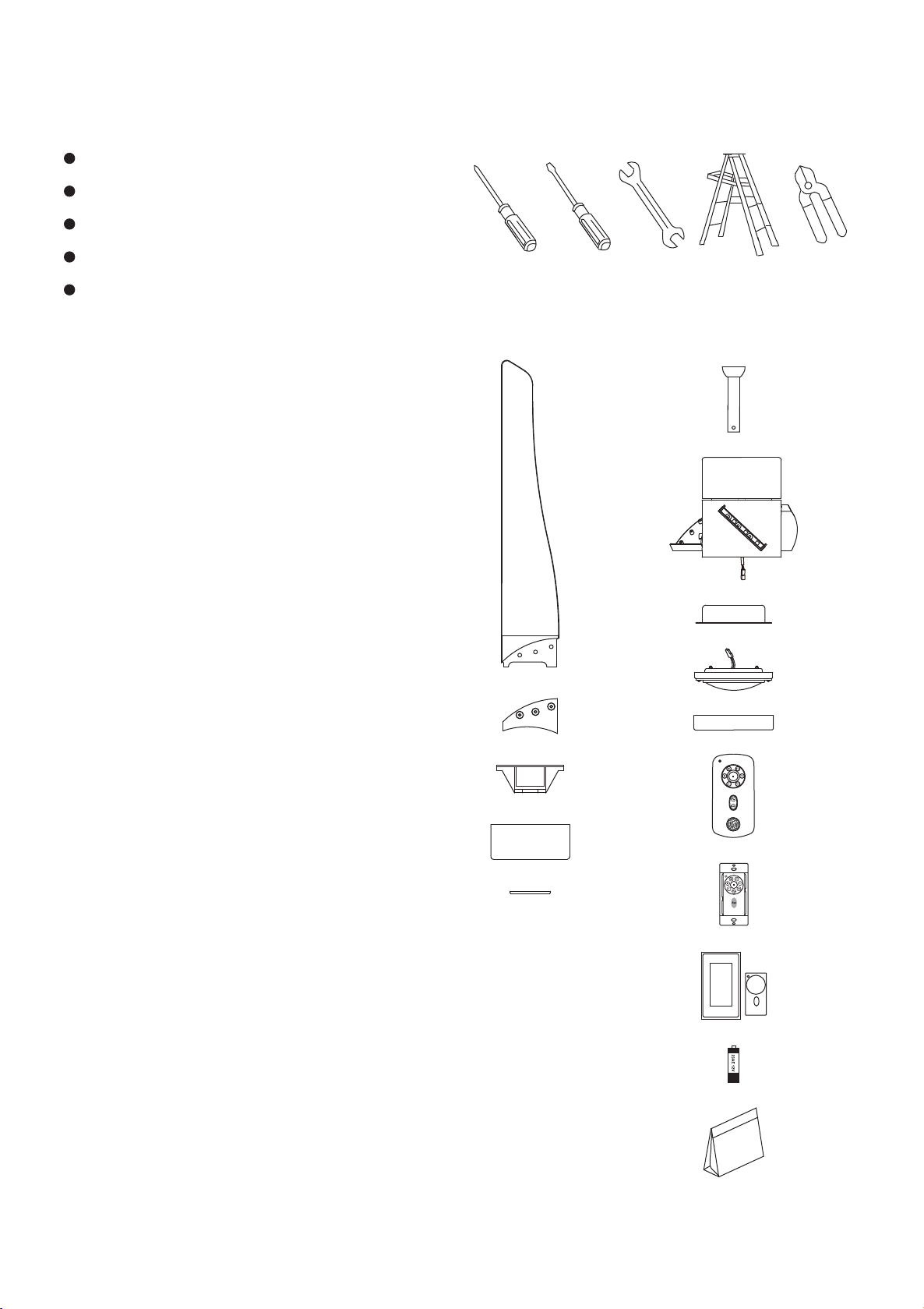
2. PACKAGE CONTENTS
Unpack your fan and check the contents. You should
have the following items:
f
a. Blade set (3)
b. Blade medallion (3)
c. Hanger bracket
d. Canopy
e. Canopy bottom cover
f. Ball / down rod assembly
g. Fan motor assembly
h. Mounting plate
i. 18W LED light kit
j. Glass shade
k. Transmitter+holder+2 mounting screws
l. Wall transmitter incl. 2 mounting screws and 3
wire nuts
m. Wall plate incl. 1 face plate and 2 mounting screws
n. 12V batteries (2)
o. Package hardware
1) Mounting hardware:
wood screws (2), screws (2),
lock washers (2), washers (2),
star washers (2), wire nuts (3)
2) Blade attachment hardware:
screws (10), fiber washers (10)
g
a
h
i
b
c
j
k
d
e
l
Please do not use any electric or battery powered
tools in the assembly and installation of this or any
Matthews Fan Company product.
m
n
o
1
3. SAFETY RULES
1. To reduce the risk of electric shock, insure
electricity has been turned off at the circuit
breaker or fuse box before beginning.
2. All wiring must be in accordance with the
National Electrical Code and local electrical
codes. Electrical installation should be
performed by a qualified licensed electrician.
3. WARNING: To reduce the risk of electrical
shock and fire, do not use this fan with any
solid-state fan speed control device.
4. WARNING: To Reduce The Risk Of Fire,
Electric Shock, Or Personal Injury, Mount To
Outlet Box Marked Acceptable for Fan
Support of 15.9 kg (35 lbs) or less And Use
Mounting Screws Provided With The Outlet
Box. Most outlet boxes commonly used for
the support of lighting fixtures are not
acceptable for fan support and may need to
be replaced, consult a qualified electrician if
in doubt.
5. The fan must be mounted with a minimum of
7 feet clearance from the trailing edge of the
blades to the floor.
6. To operate the reverse function on this fan,
press the reverse button while the fan is
running.
7. Avoid placing objects in the path of the
blades.
8. To avoid personal injury or damage to the fan
and other items, be cautious when working
around or cleaning the fan.
9. Do not use water or detergents when cleaning
the fan or fan blades. A dry dust cloth or lightly
dampened cloth will be suitable for most
cleaning.
10. After marking electrical connections, spliced
conductors should be turned upward and
pushed carefully up into outlet box. The
wires should be spread apart with the
grounded conductor and the equipment
-grounding conductor on one side of the
outlet box.
11. Electrical diagrams are reference only. Light
kit that are not packed with the fan must be
UL Listed and marked suitable for use with
the model fan you are installing. Switches
must be UL General Use Switches. Refer to
the Instructions packaged with the light kits
and switches for proper assembly.
WARNING
TO REDUCE THE RISK OF PERSONAL
INJURY, DO NOT BEND THE BLADE
BRACKETS (ALSO REFERRED TO AS
FLANGES) DURING ASSEMBLY OR AFTER
INSTALLATION. DO NOT INSERT OBJECTS IN
THE PATH OF THE BLADES.
NOTE
SUITABLE FOR USE IN DAMP LOCATIONS!
2
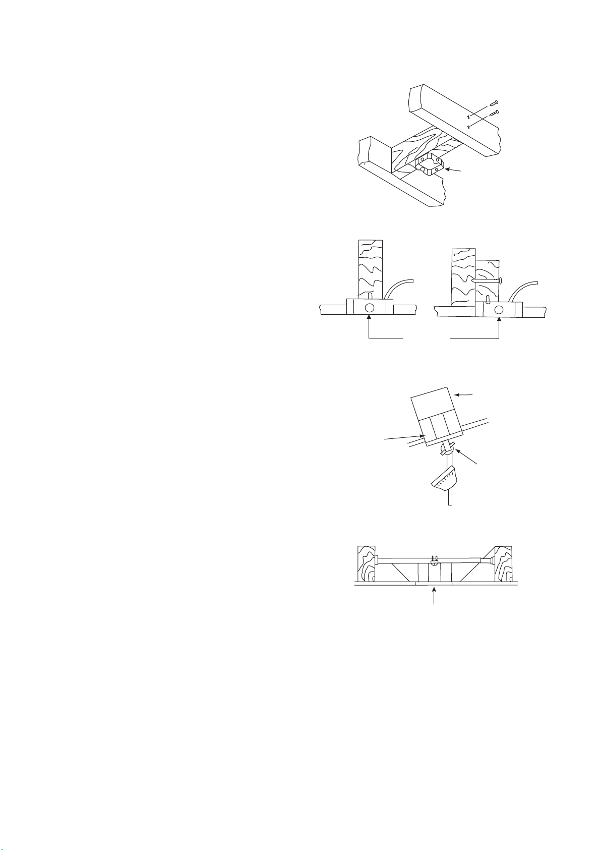
4. MOUNTING OPTIONS
If there isn't an existing UL listed mounting box,
then read the following instructions. Disconnect the
power by removing fuses or turning off circuit
breakers.
Secure the outlet box directly to the building
structure. Use appropriate fasteners and building
materials. The outlet box and its support must be
able to fully support the moving weight of the fan
15.9 kgs (35lbs) or less. Do not use plastic outlet
boxes.
Figures 1,2 and 3 are examples of different ways to
mount the outlet box.
Note: The Fig. 3 are for use for downrod style only.
Outlet box
Figure 1
Note: You may need a longer downrod to maintain
proper blade clearance when installing on a steep,
sloped ceiling. (Fig. 3)
To hang your fan where there is an existing fixture
but no ceiling joist, you may need an installation
hanger bar as shown in Figure 4.
Angled ceiling
maximum 25
Recessed
outlet box
Outlet box
Figure 2
º
Figure 3
Outlet box
Figure 4
Provide strong
support
Ceiling
mounting
bracket
3

5. HANGING THE FAN
Screws
Before touching a screw driver thoroughly
read these instructions.
Warning/Caution: Before installing fan, turn off
power at service panel and check all visible
screws and bolts for tightness.
1. Remove the metal plate and coupling cover
from the fan motor by removing the two
screws from the rim of metal plate. (Fig. 5)
2. Secure the hanger bracket to the ceiling outlet
box using screws and washers included with
your outlet box. (Fig. 6)
4. Remove hanger ball from down rod assembly
by loosening set screws, removing the cross
pin and sliding ball off rod. (Fig. 7)
5. Loosen the two set screws and remove the
hitch Pin and lock pin from the central
shaft/top coupling of the motor assembly.
Doing so will allow the down rod to enter the
central shaft. (Fig. 8)
6. Carefully feed the fan wires through the down
rod and pull them taut. Thread the down rod
into the central shaft and tighten with the
lock pin and hitch pin previously removed,
re-tighten the set screws against the
downrod. (Fig. 8)
Fan motor
Electrical
box
Ceiling
hanger
bracket
Collar
Hook
120V Wires
Metal plate
Coupling
cover
Figure 5
Washers
Mounting screws
(supplied with
electrical box)
Figure 6
7. Replace the metal plate and coupling cover
to the fan motor by using the screws
previously removed. (Fig. 8)
8. Slide canopy cover (with decorative side
oriented to floor) and canopy (with wide end
oriented to ceiling) onto down rod. Carefully
reinstall hanger ball onto rod. Be sure that
cross pin is in correct position, the set screw
on hanger ball is tight and that the wires are
not twisted. (Fig. 8)
4
Hanger
ball
Cross pin
Set screw
Downrod
Figure 7
 Loading...