

Page 1
Operating manual
SUNTEST XLS / XLS+
Page 2
Operating manual SUNTEST XLS / XLS+
- 2 -
1 Notes for safe operation ............................................................................................................................... 4
1.1 Explanation of the pictorial signs ................................................................................................................ 6
1.2 Instruction for safe operation ...................................................................................................................... 7
2 Installation of equipment .............................................................................................................................. 8
2.1 Supply schedule ......................................................................................................................................... 8
2.2 Packing material......................................................................................................................................... 8
2.3 Location requirements................................................................................................................................ 9
3 Description of equipment ........................................................................................................................... 10
3.1 Description of Suntest XLS....................................................................................................................... 10
3.2 Description of Suntest XLS+ .................................................................................................................... 10
3.3 Components with similar construction SUNTEST XLS / XLS+ ..................................................................11
4 Function description ................................................................................................................................... 12
4.1 Radiation and Filtering.............................................................................................................................. 12
4.2 Ventilation circuit s..................................................................................................................................... 12
4.3 Spectral distribution with additional filters ................................................................................................. 13
4.4 Sensor system in SUNTEST XLS+ .......................................................................................................... 14
4.5 Safety devices .......................................................................................................................................... 15
4.6 Safety markings ....................................................................................................................................... 15
5 Accessories ................................................................................................................................................. 16
6 Commissioning ........................................................................................................................................... 18
6.1 Mount the sample table ............................................................................................................................ 18
6.2 Assemble the radiation system................................................................................................................. 19
6.3 Connect to the power supply .................................................................................................................... 22
7 Operation and Shutdown............................................................................................................................ 23
7.1 Setting the equipment conditions.............................................................................................................. 23
7.2 St andard test procedure ........................................................................................................................... 23
7.3 Testing procedure with optional equipment............................................................................................... 23
7.4 Operation of SUNTEST XLS ................................................................................................................... 24
7.5 Operation of the SUNTEST XLS+ Program Controller .............................................................................24
7.6 Data transfer ............................................................................................................................................ 25
7.7 Shutting down........................................................................................................................................... 25
8 Calibration ................................................................................................................................................... 26
8.1 Calibration of the irradiance with the XenoCal Global-Sensor .................................................................. 26
8.2 Calibration of the irradiance with the Radialux Global-Sensor .................................................................. 27
8.3 Calibration of the black standard temperature .......................................................................................... 28
9 Cleaning / Consumables............................................................................................................................ 29
9.1 Cleaning ................................................................................................................................................... 29
9.2 Consumables / Sp are p arts ...................................................................................................................... 30
10 Maintenance ................................................................................................................................................ 31
10.1 Maintenance and care .............................................................................................................................. 31
10.2 Commissioning......................................................................................................................................... 31
1 1 Technical dat a.............................................................................................................................................. 31
Content Page
Page 3
- 3 -
Operating manual SUNTEST XLS / XLS+
List of graphics Page
Fig.1 Description of Suntest XLS....................................................................................................................... 10
Fig. 2 Description of Suntest XLS+ .................................................................................................................... 10
Fig. 3 Components with similar construction SUNTEST XLS / XLS+ ..................................................................11
Fig. 4 Test chamber ............................................................................................................................................11
Fig. 5 Radiation and Filtering.............................................................................................................................. 12
Fig. 6 Ventilation circuits..................................................................................................................................... 12
Spectral distribution with additional filters ................................................................................................. 13
Fig. 7 Sensor system in SUNTEST XLS+ .......................................................................................................... 14
Fig. 8 Safety devices .......................................................................................................................................... 15
Fig. 9 Safety markings ....................................................................................................................................... 15
Fig. 10 Mount the sample table ............................................................................................................................ 18
Fig. 1 1 Components of the radiation system ........................................................................................................ 19
Fig. 12 Open the assembly compartment............................................................................................................. 19
Fig. 13 Installation of the optical filter ................................................................................................................... 20
Fig. 14 Installation of the Xenon lamp .................................................................................................................. 20
Fig. 15 Installation of the reflector mirror .............................................................................................................. 21
Fig. 16 Close the assembly compartment ............................................................................................................ 21
Fig. 17 Connect to the power supply .................................................................................................................... 22
Fig. 18 St andard Test Procedure .......................................................................................................................... 23
Fig. 19 Operation of SUNTEST XLS .................................................................................................................... 24
Fig. 20 Operation of the SUNTEST XLS+ Program Controller ............................................................................. 24
Fig. 21 Data transfer to a PC (pin configuration) .................................................................................................. 25
Fig. 22 Calibration of the irradiance with the XenoCal Global Sensor.................................................................. 26
Fig. 23 Calibration of the irradiance with the Radialux Global Sensor .................................................................. 27
Fig. 24 Calibration of the black standard temperature.......................................................................................... 28
Page 4

Operating manual SUNTEST XLS / XLS+
- 4 -
Dear user,
Please note that certain kinds of work must only be carried out by personnel who are suitably qualified:
• The SUNTEST XLS and SUNTEST XLS+ may be operated only by trained and authorized laboratory personnel.
• The equipment should only be cleaned by trained personnel.
• This operating manual describes the SUNTEST XLS and the SUNTEST XLS+ weathering equipment.
• Please read the Operating manual carefully before using the SUNTEST XLS / XLS+. You will then be able to
exploit all the advantages that the equipment offers and prevent damage.
• In case unusual problems occur, that have not been treated in sufficient detail in this operating manual, please
contact the supplier for your safety .
1
Notes for safe operation
A TLAS Material Testing Technology GmbH
V ogelsbergstr . 22
63589 Linsengericht
Germany
Phone ++ 49 / 6051 / 707-140
Fax ++ 49 / 6051 / 707-149
Page 5

- 5 -
Operating manual SUNTEST XLS / XLS+
1
Notes for safe operation
Dear User:
• This equipment has been manufactured according to the state-of-the-art and is operationally safe. Nonetheless,
there may be some danger from this equipment, especially if it is operated by personnel who are not adequately
trained, or if it is used in an improper manner, and not used for its intended purpose.
• For personnel working with or on this equipment, the operating agency must provide written instructions, in an
easy-to-understand form, based on these instructions, and make it available in the natural language of the employee (FRG: Accident Prevention Act, UVV VGB 1 § 7, 2).
• Based on these instructions, train the operating and cleaning personnel in the function, operation and maintenance of this equipment.
• The contents of this operating manual are subject to change at any time without prior notice.
• The German version of this operating manual is binding in the case of translations in other, foreign languages.
• For reasons of safety, changes or modifications to the equipment on your own initiative are not permitted.
Please keep this operating manual carefully and accessibly in the vicinity of your equipment, so that safety
instructions and important information can be looked up at any time.
Trade marks:
All the trade marks in the instructions are the exclusive property of the respective manufacturers.
Copyright
©
1999 ATLAS MTT GmbH • D-63589 Linsengericht • Germany
Edition dated:
November 1999
Page 6
Operating manual SUNTEST XLS / XLS+
- 6 -
1
Notes for safe operation
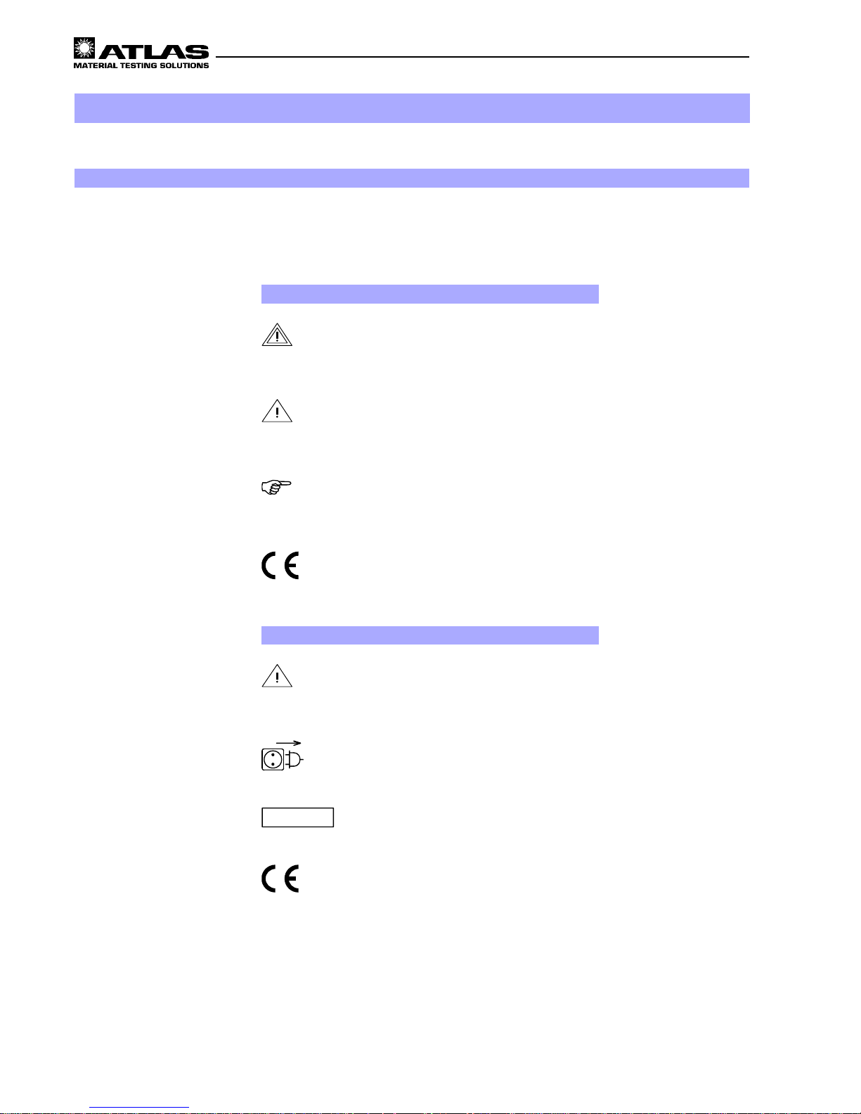
1.1 Explanation of the pictorial signs
Safety symbols will draw your attention to safety-critical operating errors.
Symbols used in the operating manual
WARNING!
Non-compliance with these can result in serious or even
fatal injury .
CAUTION!
Non-compliance with these can result in medium to light
personal injury or damage to property .
Note!
Provides usage tips and useful information.
CE - Conformance mark
Symbols on the equipment
CAUTION - Carefully follow operating instruc-
tions!
warns of possible danger.
Pull out power plug
warns against touching live parts of the equipment.
Do not open!
Do not open!
warns against opening the gas pressure spring.
CE - Conformance mark
Page 7
- 7 -
Operating manual SUNTEST XLS / XLS+
1.2 Instructions for safe operation
1
Notes for safe operation
Please follow the safety instructions in the individual chapters.
Usage as authorized:
• SUNTEST XLS / XLS+ are used for exposure and weathering of material samples.
• The equipment is suitable for continuous operation.
• The equipment has been tested for electromagnetic compatibility and for installation in an industrial application.
Unauthorized usage:
• No substances or materials that are inflammable or that can explode should be used in the test chamber .
• No substances or materials that may release toxic substances in any form should be used in the test chamber .
• The equipment may not be used for drying or heating objects or foodstuffs.
Safety instructions for commissioning:
WARNING - Pull out the power plug:
Coming in contact with live parts can result in a possibly fatal electrical shock.
When assembling the radiation system, set the ON (I) / OFF (O) switch to the „OFF (O)“ position and pull out the
power plug. Secure the power plug from being inserted again.
W ARNING - UV-radiation being emitted: :
If the sample table is not used, UV -radiation is emitted at the bottom of the equipment and can result in damage to the
skin of the face and the retina. The sample table should always be used when the equipment is running !
CAUTION - cuts and gashes:
The optical filters have sharp edges that can result in cut wounds.
Hand-gloves must be worn at all times when working on the radiation unit.
The equipment fulfills the following safety specifications:
• DIN EN 292, Part 1:1991-11, Part 2:1995-06
Safety of machinery
• DIN EN 61010 Part 1:1994-05
Safety requirements for electrical equipment for measurement, control and laboratory use. General requirements.
• DIN EN 50178 (VDE0160): 1998-04
Electronic equipment for use in power installations.
• DIN EN 50082 (VDE 0839) Part 1:1997-11
Electromagnetic compatibility (EMC), Generic immunity standard. Part 1: Residential, commercial and light industry . Part 2: Industrial area.
Disposal:
• Please dispose of the packing materials according to the applicable disposal guidelines. There is a list given in
chapter 2.2, „Packing Material“.
• Xenon lamps are special waste and may be sent to ATLAS MTT B.V. for disposal.
• Old equipment contains re-usable materials. Therefore, please do not simply dispose of old equipment at the
nearest garbage dump, but ask your city or community administration about the possibilities of recycling.
Page 8
Operating manual SUNTEST XLS / XLS+
- 8 -
2.1 Supply schedule
The weathering equipment is available in two versions, the SUNTEST XLS or SUNTEST XLS+ .
The basic equipment of the SUNTEST XLS consists of:
• Xenon Lamp,
• Optical filter „coated quartz dish",
• UV reflector and light mirror,
• 2 Z-Rails,
• Sample table,
• Sensor for measurement and regulation of the irradiance (E),
• Control panel with rotary switch for stepless adjustment of the irradiance, Xenon lamp operating hour
meter and ON/OFF switch of the Xenon lamp.
• ON / OFF switch
SUNTEST XLS+ is equipped with the following:
• Xenon Lamp,
• Optical filter „coated quartz dish“,
• UV-reflector and light mirror ,
• Sample table,
• 2 Z-Rails,
• Sensor for measurement and control of the irradiance
(E),
• Sensor for measurement and control of the black standard temperature (BST),
• Sensor for measuring the test chamber temperature
(CHT),
• Program controller with a display for displaying data
and keyboard for data input,
• ON (I) / OFF (O) switch,
• Serial RS 232-port for connecting to a PC or a printer.
2
Installation of equipment
2.2 Packing material
• Impregnated wood palette made of compound wood
• Polyethylene foil (PE)
• Polyethylene foam (PE)
• Corrugated cardboard
• Plastic wrapping ribbon (PP)
Page 9
- 9 -
Operating manual SUNTEST XLS / XLS+
2
Installation of equipment
2.3 Location requirements
Climatic conditions required for the place of installation:
• During continuous operation, the hot air emitted by
the air-cooling system results in a constantly changing climate in the room. Therefore, the SUNTEST
equipment should only be installed in air-conditioned,
sufficiently ventilated places of installation.
• The places of installation must be kept free of dust.
• The room temperature must be maintained between
18°C and 25°C.
• The max. relative humidity should be 70%.
The requirement for coolant air is as follows:
• Lamp cooling 250 m³/h,
• Air conditioner for the test chamber 340 m³/h.
Installation:
• Dimensions of equipment (width x depth x height):
930 mm x 500 mm x 485 mm,
• Weight of equipment approx. 80 kg,
• The equipment must be set up on a sufficiently stable
laboratory bench with a non-flammable support underneath and the laboratory bench should be aligned
so that it is horizontal.
• Please lift the unit for any displacement to avoid that
the rubber feet fall off the fixing screws.
Caution - Overheating of the equipment:
Blocking of the air inlet and air outlets can result in
overheating and damage to the equipment!
When installing the equipment, the following minimum distances to the neighboring walls or objects
must be maintained:
to the front 700 mm
to the back 500 mm
to both sides 300 mm
on top 400 mm.
Page 10
Operating manual SUNTEST XLS / XLS+
- 10 -
!
Covering hood
"
Rotary switch for setting the irradiance
#
Xenon lamp operating hour meter
$
Switch for Xenon lamp
%
ON (I) / OFF (O) switch
&
Test chamber door
Figure 1
3
Description of equipment
Figure 2
!
Covering hood
"
Control panel
#
Numeric keypad
$
Display
%
ON (I) / OFF (O) Switch
&
RS 232 port for data transfer to a PC
'
Test chamber door
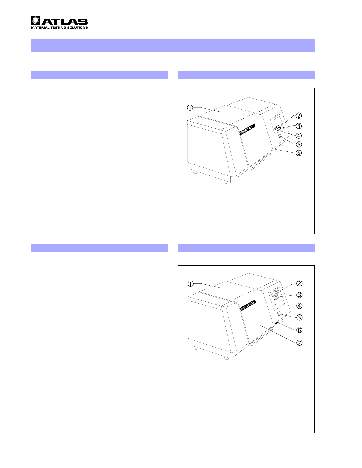
3.1 Description of SUNTEST XLS
SUNTEST XLS facilitates manual running of the testing
programs. The irradiance that has been set is controlled
at a constant value throughout the test duration.
Upper side of the equipment:
• Covering hood ! of the assembly compartment for
the lamp and filter system.
Front side of the equipment:
• Rotary switch " for setting the irradiance,
• Xenon lamp operating hour meter #,
• ON/OFF switch $ for Xenon lamp,
• ON (I) / OFF (O) switch %,
• Test chamber door &.
3.2 Description of SUNTEST XLS+
SUNTEST XLS+ is equipped with a microprocessor-based controller for measurement and regulation and works
with software-controlled testing programs.
Upper side of the equipment:
• Covering hood ! of the assembly compartment for
the Xenon lamp and filtering system.
Front side of the equipment SUNTEST XLS+:
• Control panel " with
• Numeric keypad # and
• Display $,
• ON (I) / OFF (O) switch %,
• RS 232 port & for data transfer to a PC or printer ,
• Test chamber door '.
Page 11

- 11 -
Operating manual SUNTEST XLS / XLS+
3
Description of equipment
Figure 3
!
Air outlet for Xenon lamp cooling
"
Port for connecting the optional cooling equipment
/flooding equipment
#
Power plug with connecting cable
$
Air inlet opening - test chamber
%
Air inlet opening Xenon lamp cooling
Figure 4
!
Gas pressure spring
"
Test chamber door
#
Reflector
$
Xenon lamp
%
Photodiode for measurement of the irradiance
&
Black standard sensor (BST)
'
Air inlet for temperature control in the
test chamber
(
Sample table
T est chamber: Fig. 4
• Gas pressure spring ! for easy opening / closing the
test chamber door ".
• The reflector # is located in the test chamber, and
the Xenon lamp $ at the top of the test chamber,
• The photo-diode % measures the irradiance,
• The black standard sensor (BST) & (only in XLS+)
measures the black standard temperature at sample
level,
• Air inlet ' for temperature control in the test
chamber,
• the sample table ( is used for locating or fixing the
specimens.
3.3 Components with similar construc-
tion SUNTEST XLS / XLS+ Figure 3 / 4
The rear side of the equipment and the test chamber
are similar in design in both models.
Rear side of the equipment: Fig. 3
• Air outlet ! of the Xenon lamp cooling,
• Port " for connecting the optional cooling device /
flooding device,
• Power plug with connecting cable #,
• Air inlet opening $ of the test chamber,
• Air inlet opening % for Xenon lamp cooling.
Page 12

Operating manual SUNTEST XLS / XLS+
- 12 -
• The specimens ! are placed on the sample table ".
The radiation $ is generated by the Xenon-Lamp #.
The radiation $ is filtered through an optical filter
"coated quartz dish"
%.
Note!
There are optional filters (see Chapter 5, „Accessories’)
available for various spectral distributions (see chapter.
4.1.3, „Spectral distribution with additional filters“).
• The UV-component of the radiation, that is directed
upwards, is reflected on the specimens ! by the
mirrors & that are placed above the Xenon lamp #.
• The components of the non-dangerous IR-radiation
(heat radiation) are absorbed by an absorber, and removed out of the equipment via the air circuit of the
Xenon lamp.
4
Function description
Figure 5
!
Specimens
"
Sample table
#
Xenon lamp
$
Radiation
%
Optical filter " coated quartz dish"
&
Mirror
!
Cooling air supply (inlet), test chamber
"
Cooling air outlet, test chamber,
lower side of the device
#
Cooling air supply Xenon lamp
$
Cooling air outlet, Xenon lamp
4.1 Radiation and Filtering
4.2 Ventilation circuits
• The coolant air of the test chamber ! is sucked inward on the rear side of the equipment (see chapter
3.3, „Rear side of equipment“) through an air filter,
flows through the test chamber and exits at the bottom of the equipment ".
• The coolant air of the Xenon lamp # is drawn in on
the rear side of the equipment (see chapter 3.3,
“Rear side of equipment”) through an air filter, flows
through the Xenon lamp compartment and exits again
on the exhaust opening on the rear side $.
NOTE!
During continuous operation, the hot air emitted by the
air cooling system results in a continuous change in the
labboratory climate.
Figure 6
IR-Radiation
(heat radiation)
UV-Radiation and
visible light
Page 13

- 13 -
Operating manual SUNTEST XLS / XLS+
4
Function description
Figure: Spectra
4.3 Spectral distribution with
additional filters
0
1
2
3
4
5
6
200 300 400 500 600 700 800 900
Wavelength (nm)
Irradiance (W/(m²xnm))
UV-Special glass
CIE85 (Table 4)
SUNTEST XLS / XLS+
E (300nm - 800nm) = 765 W/m²
0
0,5
1
1,5
2
2,5
3
250 270 290 310 330 350 370 390 410 430 450
W a velength (nm)
Irradiance (W/(m²xnm)
UV MAX
UV-Special glass
Special-w indow glass
SUNTEST XLS / XLS+
E (300nm - 800nm) = 765 W/m²
Page 14

Operating manual SUNTEST XLS / XLS+
- 14 -
4
Function description
4.4 Sensor system in SUNTEST XLS+
SUNTEST XLS+ has integrated sensors:
• Sensor for measuring and controlling the irradiance
(E) in the range 300 - 800nm,
• Sensor for measuring and regulating the black standard temperature (BST) in the range ambient temperature up to about 90°C,
• Sensor for measuring the test chamber temperature
(CHT).
Irradiance (E):
• During the testing, the irradiance is measured by a
photo-diode ! and controlled electronically to achieve a constant value.
Black Standard Temperature (BST)
• During the testing, temperature measurements are taken continuously by the black standard-sensor (BST)
".
• The black standard temperature (BST) is controlled
via the speed of the test chamber ventilator.
T est chamber temperature (CHT):
• The test chamber temperature (CHT) is measured by
a temperature sensor in the exhaust air flow of the
test chamber.
• The test chamber temperature cannot be controlled.
The test chamber temperature is indicated in the display unit of the program controller.
Measurement data:
• The measured data can be transferred, with the testing program running, via the RS 232-port # to a PC
or a printer with a serial interface.
!
Photodiode for measurement of the irradiance
"
Black standard-Sensor (SST)
#
RS 232 port for data transfer
Figure 7
Page 15

- 15 -
Operating manual SUNTEST XLS / XLS+
!
ON (I) / OFF (O) switch
"
Door switch for test chamber door
#
Safety switch for covering hood
$
Gas- pressure spring
4
Function description
Figure 8
4.5 Safety devices
There are safety and protection devices that increase the operational and functional safety of the equipment:
• T o switch off the equipment in an emergency, set the
ON (I) / OFF (0) switch ! to position “OFF (0)”.
• A door switch switches off the equipment when the
test chamber door " is opened.
• A safety switch interrupts the power supply when the
covering hood # is pushed back.
• The gas-pressure spring $ on the door of the test
chamber stabilizes the door in its open position.
• A temperature safety device switches off the equipment if there is a danger of the Xenon lamp getting
overheated because of insufficient cooling.
Figure 9
4.6 Safety markings
Please check whether the safety markings mentioned below have been put on the equipment.
If any of the safety markings should be absent, please inform your supplier.
• The safety notice “Pull out power plug” ! on the absorber provides a warning about touching live parts of
the equipment.
• The safety notice “Warning of danger" " on the absorber warns about touching the radiation system
when it is hot and about sharp edges on the optical
filter and reflecting mirror.
• The safety notice “Warning of danger” # on the door
of the test chamber warns of a possible danger of
fingers getting caught in the door of the test chamber
if the door is closed abruptly , and of touching hot specimens.
So also, there is a warning about the dangers of the
UV-radiation being emitted if the sample table is not
fitted.
• The notice “Do not open!” $ on the gas pressure
spring warns about opening the gas pressure spring,
which is under high tension.
4
2
1
3
!
Pull out the plug
"
Warning of danger
#
Warning of danger
$
Do not open
Nicht öffnen!
Page 16

Operating manual SUNTEST XLS / XLS+
- 16 -
5
Accessories
Item Accessories Description Ident no.:
1Sensors:
1.1 XenoCal UV sensor Measurement and calibrati on of the i rradiance;
measurement range 300 - 400 mm
5500 7270
1.2 XenoCal Global s ens or Measurement and calibrati on of the i rradiance;
measurement range 300 - 800 mm
5500 7271
1.3 A dapt er for XenoCal sensors Holding plate for insert i on of the XenoCal sensor
in t h e tes ting chamber
5607 7895
1.4 B lack standard sensor (BST) Measurement of t he black standard temperat ure
(BST)
5600 1490
1.5 White standard sensor (WS T) Measurement of t he whit e standard tem perature
(WST) with digital display
5600 1491
1.6 White standard sensor (WS T) Measurement of t he whit e standard tem perature
(WS T), (s eparate readout device required)
5607 7906
1.7 Adapt er for SST and WST s ensor Holdi ng p l ate for ins e rting the B S T and WST
sens ors in the tes t chamber
5607 7928
1.8 XENOV IEW, s eri al 9-pole Software pack age for transferring the t est
parameters to a PC
5607 6813
1.9 XENOV IE W, serial 25 -pole Soft ware pack a ge for t ra nsferring the te st
parameters to a PC
5607 6812
2 Filter:
2.1 UV special gl as s In addition to the coat ed quartz dis h for working
with wave lengths greater than 290 mm
5605 2371
2.2 S pec i al wi ndow glas s In addition to the coat ed quartz dis h for working
with wavelengths greater than 310 mm
5605 2372
2.3 S olar s tandard Filter acc ording t o COLIPA and DIN 67501 5607 7759
2.4 Solar ID65 Fil ter for il l uminating acco rdi n g to th e ICH
Guideline
5607 7769
2.5 Uncoat ed quartz dis k Instead of the c oat ed quartz dis h for higher
black st andard t em peratures
5605 2373
3 Te sting table
3.1 Water-c ool ed sampl e table For ill uminating temperature-s e nsitive materi a l s 5607 8013
4 Covering sheet
4.1 S et of covering sheets Covering s heet s for direct visual c om parison of
the weathered and unweathered test areas
5607 7980
Page 17

- 17 -
Operating manual SUNTEST XLS / XLS+
5
Accessories
Item Accessories Description Ident no.:
5 Flooding device:
5.1 F l ood in g device wi t h u ndercarriage,
flooding t ub and i nsert i on pl ate
For cy clic wet t i ng of spec im ens 5607 7932
5.2 Spec imen fastening for floodi ng device 5607 7977
6 Cooling a sse m bl y SunCool
6.1 Cooling assembly SunCool
230V 50 Hz
SunCool for reducing the t em pe rat ure i n the te st
chamber by 12ºC - 16ºC
5607 7978
6.2 Connect i on set (ri ght-hand) for Su nCool
230V, 50 Hz
Connection s tubs for connect i ng S unCool /
SUNTEST (installation to the right of SUNTEST)
5607 7981
6.3 Connection set (bottom) for SunCool
230 V, 50 Hz
Connection s tubs for connect i ng S unCool /
SUNTE ST (inst a l lat i o n b elow S UNTE ST)
5607 7982
6.4 Venti l a t i o n baffle pl ate
230V 50 Hz
For gui ded removal of t he h ot e xhaus t air of th e
cooling ass em bl y (520 c m ³/h)
5607 7985
6.5 Cool i ng a ssem b l y SunCool
115 V; 60 Hz
SunCool for reducing the t esti n g chamber
tem pe rat u re by 12ºC - 16ºC
5607 7979
6.6 Connect i on set (ri ght-hand) for Su nCool
115 V, 60 Hz
Connection s tubs for connect i ng S unCool /
SUNTEST (installation to the right of SUNTEST)
5607 8014
6.7 Connection set (bottom) for SunCool
115 V, 60 Hz
Connection s tubs for connect i ng S unCool /
SUNTE ST (inst a l lat i o n b elow S UNTE ST)
5607 8015
6.8 Ventilation baffle plate (bottom)
115 V, 60 Hz
For gui ded removal of t he h ot e xhaus t air of th e
cooling ass em bl y (520 m
3
/h)
5607 7986
6.9 Troll ey for cool i ng device In case of ins tall ation bel ow SUNTEST 5607 7857
6.10 Set of ins ul ation pads For preventing condensate water on t he surface
of the S UNTES T equipm e nt
5607 7983
Page 18

Operating manual SUNTEST XLS / XLS+
- 18 -
6
Commissioning
6.1 Mount the sample table
WARNING - UV-radiation being emitted:
If the sample table is not used, UV-radiation is emitted on the lower side of the equipment and can result in damage to the skin and the retina.
The sample table should always be used when the
equipment is running!
1. Open the sample table door ! with the handle ".
2. Mount the sample table # in such a way that the sensor receptacle $)for the black standard sensor is at
the test chamber door !.
3. Insert the black standard sensor % in the sensor locator $.
Figure 10
!
Test chamber door
"
Handle
#
Sample table
$
Sensor receptacle for the black standard sensor
%
Black standard sensor
Page 19

- 19 -
Operating manual SUNTEST XLS / XLS+
!
Optical filter "coated quartz dish"
"
Optional additional filter
#
Z-Rail
$
Xenon lamp
%
UV mirror (transparent)
&
Light mirror (mirror coating)
Figure 11
6.2.1 Components of the radiation system
The radiation system is packed separately . Please check
the components for damage before assembly . Damaged
parts should not be installed.
The radiation unit consists of:
!
Optical filter “coated quartz dish”
(optional: uncoated quartz dish),
"
Optional optical additional filters
(see chapter 5, “Accessories’),
#
the Z-Rail,
$
Xenon lamp,
%
UV mirror (transparent), pre-mounted, with
&
Light mirror (mirror coating).
NOTE!
When assembling the optical filter, put the quartz dish
(coated or optionally uncoated) and then the selected
optional additional filter in place.
6.2 Assemble the radiation system
Before the equipment can be commissioned, the sample
table and the radiation system must be assembled
CAUTION - Danger of burning:
For cooling the hot specimens and the specimen
supports, the fan continues to run even after the
equipment has been switched off.
Open the test chamber only after the fan is automatically switched off.
6
Commissioning
Figure 12
6.2.2 Open the assembly compartment
WARNING - Pull out the power plug:
Coming in contact with live parts may result in a fat al
electrical shock.
When installing the radiation systems, set the ON (I)
/ OFF (O) switch to the “OFF (O)” position and pull
out the power plug. Secure the power plug from being
re-inserted.
1. Set the ON (I) / OFF (0) switch to the “OFF (0)” position.
Pull the plug out of the socket.
Secure it against re-insertion.
2. Loosen the safety screw ! with a cross-slotted
screwdriver.
3. Push down the covering hood " towards the back till
the assembly compartment # is freely accessible
(arrow 1).
4. Remove the absorber $ from the assembly compartment # on the two retaining side plates and place
them on the housing cover (arrow 2). Do not dismantle the securing cable on the absorber.
1
2
1
2
!
Satety screw
"
Covering hood
#
Assembly compartment
$
Absorber
Page 20

Operating manual SUNTEST XLS / XLS+
- 20 -
!
Xenon Lamp
"
Lamp socket
#
Mounting
$
Cable lug
%
Threaded pin
&
Knurled nut
Figure 146.2.4 Installation of the Xenon lamp
Before installation, the Xenon lamp should first be cleaned with a starch-free cloth that is moistened with a small
amount of spirit.
NOTE!
The lamp holder is located in the assembly compartment.
1. Carefully press the Xenon lamp ! at the lamp sokket " in the mounting #.
2. Place the cable lug $ on the threaded pin % and
tighten it with the help of the knurled nut &.
6
Commissioning
!
Z-Rail 2x
"
Coated / optionally uncoated quartz dish
#
Holding frame
$
Optional filter
%
Z-Rail Holes 3x
Figure 13
6.2.3 Installation of the optical filter
Clean the optical filter before assembling with a soft leather cloth / brush. Carefully wipe the optional filter „UVspecial glass“ with a starch-free cloth that is moistened
with 20% citric acid solution.
CAUTION - Danger of cuts and gashes:
The optical filters have sharp edges that can cause
cuts and gashes.
Hand-gloves should be worn whenever working on
the radiation unit.
NOTE!
The holding frame $, in which the optical filters are placed is located in the assembly compartment.
1. Wear protective hand-gloves.
2. First, place the optical filter “coated quartz dish” or the
optional “uncoated quartz dish” # in the holding frame $.
3. Then, place the optional optical filter " (see chapter
5, “Accessories’).
4. Insert the Z-Rail ! into the assembly compartment,
with the holes % facing towards the back of the unit.
5. Position the Z-Rail on top of the lower optical filter,
ensuring a tight and flush fit against the housing wall.
Page 21

- 21 -
Operating manual SUNTEST XLS / XLS+
6
Commissioning
!
UV mirror (transparent)
"
Holding rack
#
Light mirror (mirror coating)
$
Retaining clips
%
Holes for the retaining clips
Figure 15
6.2.5 Installation of the reflector mirror
NOTE!
The reflecting mirrors are pre-mounted. When cleaning
or replacing, install the reflectors in the sequence described.
Clean the reflecting mirror before installation with a soft
leather cloth or a brush.
1. First, place the transparent UV mirror ! in the holding mounting ".
2. Then, fit the light mirror #.
3. Fix the mirrors by inserting the two retaining clips
$
in the holes %.
4. Insert the holding rack " in the radiation compartment.
!
Absorber
"
Assembly compartment
#
Covering hood
$
Safety screw
Figure 16
6.2.6 Close the assembly compartment
1. Place the absorber ! at the two holding shackles in
the assembly compartment " (arrow 1).
2. Hold the covering hood # on the outer sides and close it (arrow 2).
3. Tighten the safety screw $ with a cross-slotted
screwdriver.
4. Check for correct, sealed seating of the covering
hood #.
2
1
2
1
1
Page 22

Operating manual SUNTEST XLS / XLS+
- 22 -
6
Commissioning
6.3 Connect to the power supply
WARNING - Electrical shocks:
Coming in contact with live part s can result in a fatal
electrical shock.
Check the power plug and the supply cable for damage before connecting them.
If the power cable or the power plug is damaged, do
not connect the equipment electrically, and immediately inform the service agent.
The Suntest equipment has a single-phase power supply
through a 32A-power plug with the following parameters:
200V - 240V ± 10% at 50 / 60Hz. The supply network
must be secured (fuse settings) for 32A.
Procedure:
1. Check the supply voltage of the power supply network.
The supply voltage must be the same as that specified on the type label of the equipment.
2. Check the fuse setting of the supply with 32A.
A supply system that is not equipped with the correct
fuses can result in an electrical shock in case of failure.
3. Insert the power plug in a socket that is properly
earthed and equipped with the correct fuses.
Figure 17
230V
Page 23

- 23 -
Operating manual SUNTEST XLS / XLS+
7
Operation and Shutdown
7.1 Setting the equipment conditions
WARNING - Pull out the power plug:
Coming in contact with live part s can result in a fatal
electrical shock.
When setting the equipment conditions, set the ON
(I) / OFF (0) switch to the “OFF (0)” position and pull
out the power plug. Secure the power plug against
being inserted again.
1. Set the ON (I) / OFF (0) switch to the “OFF (0)” position.
Pull out the power plug from the power socket.
Secure the power plug from being inserted into the
socket again.
2. Use the sample table as described in chapter 6 “Com-
missioning”.
3. Insert the optical filter, the Xenon lamp and the reflecting mirror as described in chapter 6 “Commissioning”.
!
Specimens
"
Black standard-sensor (BST)
#
Sensor receptacle for the black standard sensor
$
Test chamber door
%
Handle
7.3 Testing procedure with optional
equipment
The possibilities of use of the SUNTEST XLS / XLS+
can be enhanced with various accessories (see chapter 5, „Accessories“).
• For temperature-sensitive materials:
Water-cooled sample table with a hose connection to
tap water supply .
• Cover plates:
For a direct visual comparison between illuminated
and non-illuminated specimen surfaces.
• Cooling device SunCool:
T o reduce the test chamber temperature by 12-16° C.
• Flooding device:
For cyclic wetting of specimens.
Figure 18
7.2 Standard-Testing procedure
After mounting the radiation unit, the equipment is
ready for operation. For a standardized testing procedure, please proceed as follows:
1. Center the specimens ! in the test chamber. Thin or
very light specimens ! can be fixed by optionally
placing additional cover sheets (see chapter 5, “Ac-
cessories’).
NOTE!
To be able to reproduce and compare tests, the BST
sensor must always be placed in the sensor receptacle
of the sample table.
2. Insert the black standard-sensor " (BST) in the sensor receptacle #.
CAUTION - Danger of injury:
The test chamber may close suddenly because of its
own weight. Open and close the test chamber door
only using the handle. For complete closing, press
the door slightly.
3. Close the test chamber door $ with handle %.
Page 24

Operating manual SUNTEST XLS / XLS+
- 24 -
!
Cursor keys for parameter input
"
T wo-line display for operator guidance
#
St art key, Stop key
$
Keypad for inputting the program
Figure 20
7.5 Operation of the SUNTEST XLS+
Program Controller
The program controller monitors and controls the
process of the test programs. The settings are called via the menu guide on the control panel. The menu
guide is described in the accompanying software
documentation.
The program controller provides:
• six test programs,
• with six test cycles each.
The end of the program can be selected optionally,
according to the criteria:
• T esting time (time),
• Radiant exposure (dose).
Additional program functions are:
• Programming the light and dark phases,
• Inputting the irradiance,
• Inputting the black standard temperature
The display functions are:
• Displaying the age of the lamp and equipment,
• Displaying the current testing parameters in a target/
actual comparison,
• Displaying the test chamber temperature (actual value).
7
Operation and shutdown
Figure 19
!
Rotary switch for setting the irradiance
"
Switch for igniting the Xenon lamp
#
Xenon lamp operating hour meter
7.4 Operation of SUNTEST XLS
The SUNTEST XLS has a sensor for measuring the
irradiance in the range from 300 - 800nm. The irradiance in the equipment is controlled to a constant
value.
An actual-value measurement is possible by using
the optional sensors for measuring the irradiance
(see chapter 5, “Accessories”).
1. Set the irradiance on the rotary switch !. The irradiance
can be infinitely set between 250 - 765 W/m².
NOTE!
The optional sensors „Radialux“ and „XenoCal” can be
used to measure and display the irradiance and the radiant exposure.
2. Set the ON(I) / OFF(0) switch " to the “ON (I)” posit-
ion. The Xenon lamp now gets switched on. The duration for which the Xenon lamp has been on is displayed in the Xenon lamp operating hour meter #.
NOTE!
The Xenon lamp should be replaced after every 1500
operating hours.
Cal.
0000000,0 h
I
0
ATLAS
SUNTEST --> ENTER
ESCAPE
ENTER
87
ESCAPE
4
1 2
5
9
3
6
4
0
Start Stop
Page 25

- 25 -
Operating manual SUNTEST XLS / XLS+
7
Operation and shutdown
Figure 21
SUNTEST XLS+ Personal Computer
(9-pole plug) (9-pole plug)
SUNTEST XLS+ Personal Computer
(9-pole plug) (25-pole plug)
7.6 Data transfer
The SUNTEST XLS+ has an RS 232 port for transferring the test data to a PC or a serial printer.
The data transfer to a PC or to a printer is carried out
with
the optional program XENOVIEW and facilitates the transfer of test data during a running test program.
The test data can be edited and exported to any common text processor or spreadsheet program.
A serial connection cable is required to connect the
SUNTEST XLS+ to the PC or a serial printer:
1. Connect the connection cable to a free serial port
(Com l, Com 2 etc.) of the PC
NOTE:
Note the pin configuration of the serial connection cable
for 9-pole or 25-pole plugs.
2. Connect the remaining free plug of the connection ca-
ble to the RS 232 port of the SUNTEST XLS+.
3. Before starting the program, there is a prompt whe-
ther the data transfer should be started.
7.7 Shutting down
CAUTION - Danger of burning:
For cooling the hot specimens and the specimen
supports, the fan continues to run even after the
equipment has been switched off.
Open the test chamber only after the fan is automatically switched off.
When replacing specimens, wear protective handgloves.
1. After the fan is switched off automatically , set the ON
(I) / OFF (0) switch to the “OFF (0)” position.
2. Wear protective hand-gloves.
3. Open the test chamber door using the handle and re-
move the specimens from the specimen room.
4. If required, take additional optional accessories from
the test chamber.
5. Clean the equipment according to chapter 9.1, “Cle-
aning”.
6. In case of longer pauses in operation, pull out the po-
wer plug as well.
DCD 1 1 DCD
RxD 2 2 RxD
TxD 3 3 TxD
DTR 4 4 DTR
GND 5 5 GND
DSR 6 6 DSR
RTS 7 7 RTS
CTS 8 8 CTS
RI 9 9 RI
DCD 1
RxD 2 2 TxD
TxD 3 3 RxD
DTR 4 4 RTS
GND 5 5 CTS
DSR 6 6 DSR
RTS 7 7 GND
CTS 8 8 DCD
RI 9
Printer configuration:
8 bit
Baudrate 9600
No parity
1 stop bit
Page 26

Operating manual SUNTEST XLS / XLS+
- 26 -
1
2
!
Adapter t able for XenoCal Global-Sensor
"
Sensor receptacle for the black standard sensor
#
Connector cable
$
XenoCal Global-Sensor
8
Calibration
Figure 22
8.1 Calibration of the irradiance with the
XenoCal Global-Sensor
The equipment should be calibrated before and after every test.
The optional XenoCal Global Sensor and an adapter for
the XenoCal sensor (see chapter 5 “Accessories”) are
necessary for the calibration.
1. Mount the adapter table ! for the XenoCal Global-
Sensor instead of the sample table in the test chamber.
Mount the adapter table ! in such a way that the sensor receptacle for the black standard sensor ")is at
rightfront side of the test chamber.
2. Insert the connector cable # in the XenoCal Global
sensor $ and guide the connector cable # below
the adapter table ! to the PC.
3. Start the program XenoSoft and ONLINE-measure-
ment.
4. In the Suntest XLS+, start the calibration program and
input the irradiance at which the calibration is to be
done.
5 After about 30 minutes, input the actual irradiance va-
lue displayed in the XenoSoft to the corresponding
field in the display unit and confirm with “ENTER”.
6. At the end of the automatic cooling period, the cali-
bration factor calculated by the software is indicated
in the display unit and automatically taken into account
during every subsequent test.
Test chamber door side
Page 27

- 27 -
Operating manual SUNTEST XLS / XLS+
!
Adapter for Radialux Global sensor
"
Sensor receptacle for the black standard sensor
#
Connector cable
$
Radialux Global sensor
Figure 23
8
Calibration
8.2 Calibration of the irradiance with the
Radialux Global Sensor
The equipment should be calibrated before and after every test.
An adapter for the Radialux sensor (see chapter 5 “
Accessories’) is required for calibrating the irradiance.
1 . Mount the adapter table ! for the Radialux Global
Sensor instead of the sample table in the test chamber.
Mount the adapter table ! in such a way that the sensor receptacle for the black standard sensor " is at
the right front side of the test chamber.
2. Insert the connector cable # in the Radialux-Global-
Sensor $ and guide the connector cable # below
the adapter table ! to the evaluation unit.
3. Set the evaluation unit to Global Irradiance Measure-
ment.
4. In the Suntest XLS+, start the calibration program and
input the irradiance at which the calibration is to be
done.
5. After about 30 minutes, multiply the actual irradiance
indicated in the display unit by the filter-dependent
correction factors specified in the table.
Enter the calculated value into the SUNTEST controller and confirm with “ENTER”.
6. After the automatic cooling period runs out, the cali-
bration factor calculated by the software is indicated
in the display unit and automatically taken into account
at the time of every subsequent test.
Pos. Filter Correction factor
1 Filt er A 1,00
2 Filt er B 0,96
3 Filt er C 0,92
4 Filt er D 1,12
5 Filt er E 1,10
6 Filt er F 1,08
7 Filt er G 0,90
8 Filt er H 0,96
Test chamber door side
2
1
Page 28

Operating manual SUNTEST XLS / XLS+
- 28 -
8
Calibration
8.3 Calibration of the black standardtemperature
The equipment should be calibrated before and after every test.
An optional black standard thermometer and a corresponding adapter (see chapter 5 “Accessories”) are necessary for calibrating the black standard temperature.
1. Use the adapter table ! for the black standard ther-
mometer instead of the sample table in the test chamber.
Mount the adapter table ! in such a way that the sensor receptacle for the black standard sensor " is at
the right front side of the test chamber.
2. The external black standard thermometer # should
be so placed that the black surface points upwards,
i.e. towards the Xenon lamp.
3. In the SUNTEST XLS+, start the calibration program
and input the desired black standard temperature value at the desired irradiance value (which normally corresponds to the target irradiance value resulting from
the previous irradiance calibration).
CAUTION - Danger of getting burnt:
The black standard thermometer can be very hot after a measurement has been taken.
When reading or removing the black standard thermometer from the test chamber, it may be necessary
to wear hand-gloves!
4. If required, wear protective hand-gloves.
5. After about 60 minutes, interrupt the program with
“STOP”, turn the black standard thermometer around
and immediately read the temperature in the display
of the black standard thermometer.
6. The temperature value that is read is input to the SUN-
TEST controller and confirmed with “ENTER”.
7. The calibration factor calculated by the software is in-
dicated on the SUNTEST-display and on pressing
“ENTER” again, automatically taken into account for
every subsequent test.
Figure 24
!
Adapter for black standard thermometer
"
Sensor receptacle for the black standard sensor
#
Black standard thermometer
Test chamber door side
Page 29

- 29 -
Operating manual SUNTEST XLS / XLS+
9
Cleaning / Consumables
9.1 Cleaning
WARNING - Pull out the power plug:
Coming in contact with live part s can result in a fatal
electrical shock. For all cleaning work, set the ON (I)
/ OFF (0) switch to the “OFF (0)” position and pull
out the power plug. Secure the power plug against
getting inserted again.
9.1.1 Outer surfaces and operating elements
Wipe the equipment with a mild soap solution (washing
agent) and a soft cloth.
9.1.2 Reflector
To ensure uniform illumination of the test chamber, the
reflector has to be kept clean.
CAUTION - Damage to the reflector:
The reflecting coating of the test chamber walls is
sensitive to scratches.
Do not use any solvent s, or any rough or hard cleaning agents for cleaning the reflector .
Procedure:
Wipe the reflector with a soft cloth that has been moistened with the usual commercially available washing
agents and rub dry till it is free from streaks.
9.1.3 Radiation system
The components of the radiation system must be cleaned at least every half-year. The radiation unit must be
dismantled in the opposite sequence to that described in
chapter 6.2, “Assemble the radiation system”.
Optical filters:
• Clean the optical filters with a soft leather cloth or brush
before installing them.
• Carefully wipe the optional filter “UV-special glass” with
a starchless cloth that has been moistened with 20%
citric acid solution.
Xenon lamp:
• In the cold state, clean the Xenon lamp with a starchfree cloth that is moistened with a little spirit.
Reflecting mirror:
• Clean the reflecting mirrors, before mounting, with a
soft leather cloth or a brush.
9.1.4 Air Filter
CAUTION - Damage to the equipment:
The reflector and the radiation system are dust-sensitive. Unfiltered cooling air will adversely affect the
functioning of the equipment.
The air filters must be cleaned half-yearly .
The air filters must always be installed during operation.
Procedure:
• Remove the filter mat from the filter opening on the
rear side of the equipment.
• Beat the dirty filter mat or wash it with lukewarm water and some mild soap solution (washing liquid).
If the filter mat is particularly dirty , replace it (for catalog no., see chapter 9.2, “Spare p art s”).
• Let the filter mat dry and insert it in the filter opening
again with the soft layer on the outside.
Page 30

Operating manual SUNTEST XLS / XLS+
- 30 -
9.2 Consumables / Spare parts
WARNING - approved sp are p arts:
The safety and the reliability of the equipment are
only ensured if the spare part s mentioned below are
used. Using other parts carries hidden risks and
should be avoided in all cases.
NOTE - Consumables / spare parts:
Here, you can find consumables / spare parts that can
be replaced by the user.
9
Cleaning / Consumables
Item Description Lifetime Ident no.
1
XENON lamp
NXE 2201
1,500 hours 56077798
2
Air filter at rear si de
of equipme nt (2 pcs.)
upon request 50053191
3
Optical filters:
Uncoated quartz glas s 10,000 hours 56052373
Coated quartz glas s 25,000 hours 56052388
Speci al UV gl as s (Suprax) 15,000 hours 56052371
Window glas s 4,000 hours 56052372
Solar ID 65 4,000 hours 56077769
Solar St andard 25,000 hours 56077759
Page 31

- 31 -
Operating manual SUNTEST XLS / XLS+
10
Maintenance
SUNTEST XLS / XLS+
Power supply:
Supply voltage: 200-240 V ± 10%, 50/60 Hz
Supply connection: CEE (32A, 3 pol., 6h) (1, N, PE)
Amperage: 20,5 A
Fuse rating: 32 A
Power consumption: max. 3.1 KW
Nominal rating of
Xenon-lamp: 2.2 kVA
Cooling requirement:
Lamp cooling: 250 m³/h
Air conditioner: 340 m³/h
Dimensions and weight:
Dimensions in mm: 930 x 500 x 485
(width x depth x height)
Sample table: 330 x 330 mm
Specimen surface area: about 1000 cm²
Weight: about 80 kg
Noise emission:
Noise level: < 75 dB(A)
Ambient conditions:
Room temperature: 18°C to 25°C
Relative humidity: max. 70%
Air pressure: 700 - 1060hPa
11
Technical data
10.1 Maintenance and care
At least once a year, it is necessary to ensure that the
following systems are in proper condition.
• Mechanical system
• Function (T echnical Data)
• Electrical system (BRD: UVV VGB 4)
• Safety devices of the equipment
If protective devices have been dismantled or disabled
for
the sake of maintenance work, the equipment may be
started again only after the protective devices have been
installed again and their function has been checked.
NOTE - Guarantee:
The manufacturer guarantees the safety and proper
functioning of the equipment only provided that:
• the maintenance intervals are adhered to
• all maintenance work is carried out by trained and
suitably qualified personnel,
• only original spare parts are used.
ATLAS provides a customized service package for
this equipment, consisting of a maintenance service,
measurement and calibration service that ensures the
efficiency and process safety of the equipment.
10.2 Commissioning
NOTES - Spare p arts:
We will provide a complete list of spare parts as well as
other documentation on request to suitably trained and
qualified personnel.
Page 32

A TLAS Material Testing Technology GmbH
Vogelsbergstrasse 22
D-63589 Linsengericht / Altenhasslau
Phone: + 49/6051/707-140
Fax: + 49/6051/707-149
Ident-no. 56 352 043 04.00
 Loading...