

Page 1

SUNTEST CPS / CPS+
Operating Manual
Page 2
Operating manual SUNTEST CPS / CPS+
- 2 -
1 Notes for safe operation.................................................................................................................................4
1.1 Explanation of the pictorial signs..................................................................................................................6
1.2 Instructions for safe operation ......................................................................................................................7
2 Installation of unit ..........................................................................................................................................8
2.1 Supply schedule ..........................................................................................................................................8
2.2 Packing material ..........................................................................................................................................8
2.3 Locati on requ iremen ts..................................................................................................................................9
2.4 Installation ...................................................................................................................................................9
3 Description of unit ........................................................................................................................................10
3.1 Description of Suntest CPS .......................................................................................................................10
3.2 Description of Suntest CPS+ .....................................................................................................................10
3.3 Components with similar construction SUNTEST CPS / CPS+ .................................................................. 11
4 Description of functions ...............................................................................................................................12
4.1 Radiation and filtering .................................................................................................................................12
4.2 Ventilation circuit s......................................................................................................................................12
4.3 Spectral distribution with additional filters...................................................................................................13
4.4 Sensor system in SUNTEST CPS+ ...........................................................................................................14
4.5 Safety devices ...........................................................................................................................................15
4.6 Safety markings.........................................................................................................................................15
5 Accessories ...................................................................................................................................................16
6 Commissioning .............................................................................................................................................18
6.1 Mounting of specimen table .......................................................................................................................18
6.2 Assembling the radiation system ...............................................................................................................18
6.3 Connection to power supply .......................................................................................................................21
7 Operation and shutdown .............................................................................................................................22
7.1 Confi gurat ion of u nit ...................................................................................................................................22
7.2 Standard testing procedure ........................................................................................................................22
7.3 T esting procedure with optional unit............................................................................................................22
7.4 Operation of SUNTEST CPS ......................................................................................................................23
7.5 Operation of SUNTEST CPS+ program controller ......................................................................................23
7.6 Data transfer to a PC .................................................................................................................................24
7.7 Shutdown...................................................................................................................................................24
8 Calibration ....................................................................................................................................................25
8.1 Calibration of irradiance with the XenoCal Global Sensor ............................................................................25
8.2 Calibration of irradiance with the Radialux Global Sensor ...........................................................................26
8.3 Calibratio n of the blac k standard te mperature.............................................................................................27
9 Cleaning / Consumables..............................................................................................................................28
9.1 Cleaning.....................................................................................................................................................28
9.2 Consumables / Spare parts........................................................................................................................29
10 Maintenance .................................................................................................................................................30
10.1 Maintenance and care................................................................................................................................30
10.2 Commissioning ..........................................................................................................................................30
11 Technical data ..............................................................................................................................................31
Content Page
Page 3

- 3 -
Operating manual SUNTEST CPS / CPS+
List of graphics Page
Fig. 1 Description of unit Suntest CPS.................................................................................................................10
Fig. 2 Description of unit Suntest CPS+...............................................................................................................10
Fig. 3 Components with similar construction SUNTEST CPS / CPS+ .................................................................. 11
Fig. 4 Test chamber ............................................................................................................................................. 11
Fig. 5 Radiation and filtering .................................................................................................................................12
Fig. 6 V entilation circuit s......................................................................................................................................12
Spectral distribution with additional filters...................................................................................................13
Fig. 7 Sensor system in the SUNTEST CPS+ .....................................................................................................14
Fig. 8 Safety devices ...........................................................................................................................................15
Fig. 9 Safety markings.........................................................................................................................................15
Fig. 10 Mounting of specimen table .......................................................................................................................18
Fig. 11 Components of the radiation system ..........................................................................................................18
Fig. 12 Opening the assembly compartment..........................................................................................................19
Fig. 13 Installation of optical filters .........................................................................................................................19
Fig. 14 Installation of Xenon lamp..........................................................................................................................20
Fig. 15 Installation of mirrors..................................................................................................................................20
Fig. 16 Closing the assembly compartment ...........................................................................................................21
Fig. 17 Connection to power supply .......................................................................................................................21
Fig. 18 Standard testing procedure ........................................................................................................................22
Fig. 19 Operation of SUNTEST CPS ......................................................................................................................23
Fig. 20 Operation of SUNTEST CPS+ program controller .......................................................................................23
Fig. 21 Data transfer to a PC (pin configuration).....................................................................................................24
Fig. 22 Calibration of irradiance with the XenoCal Global Sensor ............................................................................25
Fig. 23 Calibration of irradiance with the Radialux Global Sensor ...........................................................................26
Fig. 24 Calibration of the black standard temperature.............................................................................................27
Page 4

Operating manual SUNTEST CPS / CPS+
- 4 -
Dear user ,
Please note that certain kinds of work must only be carried out by personnel who are suitably qualified:
• The SUNTEST CPS/CPS+ may be operated only by trained und authorized laboratory personnel,
• The unit should only be cleaned by trained personnel.
• This operating manual describes the SUNTEST CPS and the SUNTEST CPS+ weathering units.
• Please read the Operating Manual carefully before using the SUNTEST CPS/CPS+.
Y ou will then be able to exploit all the advantages that the device offers and prevent damage.
• If unusual problems occur, that have not been treated in sufficient det ail in this operating manual, please contact the
supplier for your own safety .
1
Notes for safe operation
A TLAS Material Testing Technology B.V
V ogelsbergstr. 22
63589 Linsengericht / Altenhaßlau
Deutschland
Phone ++ 49 / 6051 / 707-140
Fax ++ 49 / 6051 / 707-149
Page 5

- 5 -
Operating manual SUNTEST CPS / CPS+
1
Notes for safe operation
Dear User:
• This unit has been manufactured according to the state-of-the-art and is operationally safe. Nonetheless, there may
be some danger from this unit, especially if it is operated by personnel who are not adequately trained, or if it is used
in an improper manner, and not for its intended purpose.
• For personnel working with or on this unit, the operating agency must provide written instructions, in an easy-tounderstand form, based on these instructions, and make it available in the natural language of the employee (FRG:
Accident Prevention Act, UVV VGB 1 § 7, 2).
• Based on these instructions, train the operating and cleaning personnel in the function, operation and maintenance
of this unit.
• The contents of this operating manual are subject to change at any time without prior notice.
• The German version of this operating manual is binding in the case of translations in other, foreign languages.
• For reasons of safety, changes or modifications to the unit on your own initiative are not permitted.
Please keep this operating manual carefully and accessibly in the vicinity of your instrument, so that safety
instructions and important information can be looked up at any time.
Trade marks:
All the trade marks in the instructions are the exclusive property of the respective manufacturers.
Copyright
©
1999, A TLAS MTT BV • D-63589 Linsengericht-Altenhaßlau • Germany
Edition dated:
March 1999
Page 6
Operating manual SUNTEST CPS / CPS+
- 6 -
Safety symbols will draw your attention to safety-critical operating errors.
Symbols used in the operating manual
WARNING!
Non-compliance with these can result in serious or even
fatal injury .
CAUTION!
Non-compliance with these can result in medium to light
personal injury or damage to property .
NOTE!
Provides usage tips and useful information.
CE - Conformance mark
Symbols on the unit
Pull out the power plug before opening the device !
Warns you not to touch live parts of the unit when you open
the device.
CE - Conformance mark
1
Notes for safe operation
1.1 Explanation of the pictorial signs
Pull mains plug
before opening !
Page 7
- 7 -
Operating manual SUNTEST CPS / CPS+
1
Notes for safe operation
Please also follow the safety instructions in the individual chapters.
Usage as authorized:
• SUNTEST CPS / CPS+ are used for exposure and weathering of material samples.
• The unit is suitable for continuous operation.
• The unit has been tested for electromagnetic compatibility and for installation in an industrial application.
Unauthorized usage:
• No substances of materials that are inflammable or that can explode should be used in the test chamber .
• No substances or materials that may release toxic substances in any form should be used in the test chamber .
• The device must not be used for drying or heating objects or foodstuffs.
Safety instructions for commissioning:
WARNING - Pull out the power plug:
Coming in contact with live parts can result in a possibly fatal electrical shock. When assembling the irradiance system, set the ON (I) / OFF (O) switch to the "OFF (O)" position and pull out the power plug. Secure
the power plug from being inserted again.
WARNING - UV radiation being emitted:
If the specimen table is not used, UV radiation is emitted on the lower side of the unit and can result in
damage to skin and retina. Always use the specimen table when the unit is running !
WARNING - UV radiation being emitted:
If the mirrors (figure 15) are not used, UV radiation is emitted on the upper side of the unit and can result in
damage to skin and retina. Always mount the mirrors.
CAUTION - Danger of cuts and gashes:
The optical filters have sharp edges that may cause cuts and gashes.
Always wear protective gloves when working on the radiation system.
The device fulfills the following safety specifications:
• DIN EN Part 1:1991-11, Part 2:1995-06
Safety of machinery
• DIN EN 60601 Part 1:1994-05
Safety regulations for electrically operated measuring, controlling, regulating and laboratory equipment. General
requirements.
• DIN EN 50178 (VDE0160): 1998-04
Electronic equipment for use in power installations
• DIN EN 50082 (VDE 0839) Part 2:1997-11
Electromagnetic compatibility , Professional Basic Norm, immunity from distortion. Part 1: Residential areas, business and industrial areas as well as small industries. Part 2: Industrial area.
Disposal:
• Please dispose of the packing materials according to the applicable disposal guidelines. There is a list given in
chapter 2.2, "Packing Material".
• Xenon lamps are special waste and may be sent to ATLAS MTT B.V. for disposal.
• Old units contain re-usable materials. Therefore, please do not simply dispose of old units at the nearest garbage
dump, but ask your city or community administration for the possibilities of recycling.
1.2 Instructions for safe operation
Page 8

Operating manual SUNTEST CPS / CPS+
- 8 -
2
Installation of unit
2.1 Supply schedule
The weathering unit is available in two versions: SUNTEST CPS or SUNTEST CPS+.
The basic unit of SUNTEST CPS consists of:
• Xenon lamp,
• Optical filter "coated quartz filter segment",
• UV mirror and light mirror,
• Specimen table,
• Sensor for measuring and regulating irradiance (E),
• Control panel with rotary switch for infinite adjustment
of irradiance, Xenon lamp operating hour meter and
switch for igniting the Xenon lamp.
• ON (I) / OFF (O) switch.
SUNTEST CPS+ is equipped with the following:
• Xenon lamp,
• Optical filter "coated quartz filter segment",
• UV mirror and light mirror,
• Specimen table,
• Sensor for measurement and control of irradiance (E),
• Sensor for measurement and control of the black standard temperature (BST),
• Sensor for measuring the test chamber temperature
(TCT),
• Program controller with a display for displaying data
and keyboard for data input,
• ON (I) / OFF (O) switch,
• Serial RS 232-port for connection to a PC.
2.2 Packing material
• Polyethylene foam (PE)
• Corrugated cardboard
Page 9
- 9 -
Operating manual SUNTEST CPS / CPS+
2.3 Location requirements
Climatic conditions required for the place of installation:
• During continuous operation, the hot air emitted by the
air-cooling system results in a constantly changing climate in the room. Therefore, the SUNTEST unit should
only be installed in air-conditioned, sufficiently ventilated places of installation.
• The places of installation must be kept free of dust.
• The room temperature must be maintained between
18°C and 25°C.
• The max. relative humidity should be 70%.
The requirement for coolant air is as follows:
• 120 m³/h for lamp cooling and cooling of the test chamber.
2
Installation of unit
2.4 Installation
Installation SUNTEST CPS / CPS+:
• Dimensions of unit (width x depth x height):
780 mm x 350 mm x 350 mm,
• Weight of unit approx. 30 kg,
• The unit must be set up on a sufficiently stable laboratory bench with a non-flammable support underneath;
the laboratory bench should be aligned so that it is
horizontal.
Caution - Overheating of the unit:
Blocking of the air inlet and air outlets can result in
overheating and damage to the unit!
When installing the unit, the following minimum distances to the neighboring walls or objects must be
maintained:
to the front: 700 mm
to the back: 500 mm
to the top: 350 mm
to both sides: 300 mm
Page 10
Operating manual SUNTEST CPS / CPS+
- 10 -
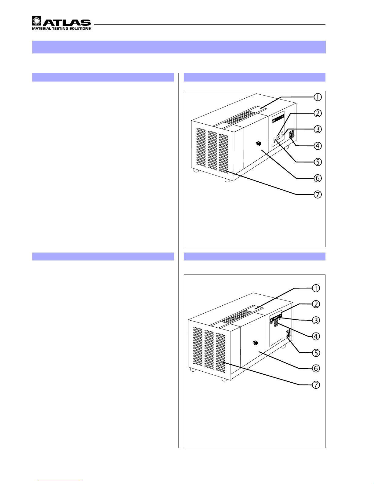
!
Covering hood
"
Xenon lamp operating hour meter
#
Rotary switch for setting the irradiance
$
ON (I) / OFF (O) switch
%
Switch for igniting the Xenon lamp
&
Test chamber door
'
Air outlet of the lamp cooling and temperature control
of the test chamber
Figure 1
3
Description of unit
Figure 2
!
Covering hood
"
Program controller
#
Display
$
Numerical keyboard
%
ON (I) / OFF (O) switch
&
Test chamber door
'
Air outlet of the lamp cooling and temperature control
of the test chamber
3.1 Description of SUNTEST CPS
SUNTEST CPS facilitates manual setting of the testing
programs. The irradiance that has been set is regulated
at a constant value throughout the test duration.
Upper side of the unit:
• Covering hood ! of the assembly compartment for
the lamp and filtering system.
Front side of the unit:
• Rotary switch # for setting the irradiance,
• Xenon lamp operating hour meter ",
• Switch % for igniting the Xenon lamp,
• ON (I) / OFF (O) switch $,
• T est chamber door &.
Left side of SUNTEST CPS:
• Air outlet ' of the lamp cooling and the temperature
control of the test chamber.
3.2 Description of SUNTEST CPS+
SUNTEST CPS+ is equipped with a microprocessor-based controller for measurement and regulation and works
with software-controlled testing programs.
Upper side of the unit:
• Covering hood ! of the assembly compartment for
the lamp and filtering system.
Front side of SUNTEST CPS+:
• Program controller " with
• Numeric keypad $ and
• Display #,
• ON (I) / OFF (O) switch %,
• T est chamber door &.
Left side of SUNTEST CPS+:
• Air outlet '(of the lamp cooling and the temperature
regulation of the test chamber.
Page 11

- 11 -
Operating manual SUNTEST CPS / CPS+
3
Description of unit
Figure 3
!
RS 232 port
"
Port for connecting the optional cooling/immersion de-
vice
#
Air inlet opening for lamp cooling and temperature
regulation of the test chamber
$
Power plug with connecting cable
%
Air outlet of the lamp cooling and the temperature
regulation of the test chamber
Figure 4
!
Door lock switch
"
Test chamber door
#
Reflector
$
Photodiode for measuring irradiance
%
Air inlet for temperature regulation in the testing
chamber
&
Black standard sensor (BST sensor)
'
Specimen table
T est chamber: Fig. 4
• Door lock switch ! for opening / closing the test chamber door ".
• The reflector # is located in the test chamber and in
the test chamber door. The Xenon lamp is located in
the roof of the test chamber.
• The photodiode $ measures the irradiance E,
• The black standard sensor (BST sensor) & (only in
CPS+) measures the black standard temperature at
the specimen level.
• Air inlet % for temperature control in the test
chamber.
• The specimen table ' is used for positioning the specimens.
3.3 Components with similar construction
SUNTEST CPS / CPS+ Figures 3 / 4
The rear sides of the units and the test chambers are
similar in design in both models.
Rear side of the unit: Fig. 3
• Air inlet opening # for the Xenon lamp cooling and
the temperature regulation of the test chamber,
• Port " for connecting the optional cooling device or
immersion device (only SUNTEST CPS+),
• RS 232 port for data transfer to a PC (only SUNTEST
CPS+),
• Power plug with connecting cable $,
• Air outlet % of the lamp cooling and the temperature
regulation of the test chamber.
Page 12

Operating manual SUNTEST CPS / CPS+
- 12 -
• The specimens & are placed on the specimen table
%
. Radiation $ is generated with a Xenon lamp
#
and filtered through an optical filter "coated quartz filter segment"
".
NOTE:
There are optional optical filters (see Chapter 5 "Accessories") available for various spectral distributions (see
chapter. 4.3, "S pectral distribution with additional filters").
• The UV component of the radiation that is directed
upwards is reflected on the specimens & by the mirrors ! placed above the Xenon lamp #.
• The components of the non-dangerous IR radiation (heat
radiation) might penetrate through the mirrors. The
remaining heat is removed out of the unit via the air
circuit of the Xenon lamp.
4
Description of functions
Figure 5
!
Coolant air supply Xenon lamp and
regulation of test chamber temperature
"
Coolant air outlet Xenon lamp and
regulation of test chamber temperature
4.1 Radiation and Filtering
4.2 Ventilation circuit s
• The coolant air of the Xenon lamp and the test chamber ! is aspirated on the rear side of the unit (see
chapter 3.3, "Rear side of unit") through an air filter,
flows through the test chamber and the assembly compartment of the irradiance unit and exits through the
exhaust openings "(at the left and the rear side of
the unit (see chapter 3.3, "Rear side of unit").
NOTE:
During continuous operation, the hot air emitted by the air
cooling system results in a continuous change in the climate inside the chamber.
Figure 6
!
Mirrors (UV and light mirrors)
"
Optical filter "coated quartz filter segment"
#
Xenon lamp
$
Radiation
%
Specimen table
&
Specimens
Page 13

- 13 -
Operating manual SUNTEST CPS / CPS+
4
Description of functions
4.3 Spectral distribution with additional filters
Figures: Spectra
0
0,5
1
1,5
2
2,5
3
250 300 350 400 450 500
Wavelength (nm)
Irradiance [W/(m²xnm)]
UV MAX
UV special glass
Special window glass
SUNTEST CPS/CPS+
E(300nm-800nm) = 765W/m²
0
1
2
3
4
5
6
200 300 400 500 600 700 800 900
Wavelength (nm)
Irradiance [W/(m²xnm)]
UV special glass
CIE85 (Table 4)
SUNTEST CPS/CPS+
E(300nm-800nm) = 765W/m²
Page 14

Operating manual SUNTEST CPS / CPS+
- 14 -
4
Description of functions
4.4 Sensor system in SUNTEST CPS+
SUNTEST CPS+ has integrated sensors:
• Sensor for measuring the global irradiance (E) in the
range of 300 - 800 nm and for regulation in the range of
250 -765 W/m²,
• Sensor for measuring and regulating the black standard temperature (BST) up to about 100 °C,
• Sensor for measuring the test chamber temperature
(TCT).
Irradiance (E):
• During testing, irradiance is measured by a photodiode
!
and regulated electronically to achieve a constant
value.
Black Standard Temperature (BST)
• During testing the black standard sensor (BST sensor) " continuously measures the temperature.
• The black standard temperature (BST) is regulated via
the speed of the test chamber ventilator.
T est chamber temperature (TCT):
• The test chamber temperature (TCT) is measured by a
temperature sensor in the exhaust air flow of the test
chamber.
• The test chamber temperature cannot be controlled
and is indicated in the display unit of the program controller.
Measurement data:
• The measurement data can be transferred, with the
testing program running, via the RS 232-port at the
rear side of the unit to a PC or a printer with a serial
interface.
!
Photodiode for measuring irradiance
"
Black standard sensor (BST sensor)
Figure 7
Page 15

- 15 -
Operating manual SUNTEST CPS / CPS+
!
ON (I) / OFF (O) switch
"
Door switch for test chamber door
#
Safety switch for lamp replacement
$
T emperature safety device
4
Description of functions
Figure 8
4.5 Safety devices
There are safety and protection devices that increase the operational and functional safety of the unit:
• T o switch off the unit in an emergency, set the ON (I) /
OFF (0) switch ! to position "OFF (0)".
• A door switch switches off the unit when the test chamber door " is opened.
• A safety switch interrupts the power supply when the
covering hood # of the assembly compartment is removed.
• A temperature safety device $ switches off the unit if
there is a danger of the Xenon lamp getting overheated
because of insufficient cooling.
Figure 9
4.6 Safety markings
Please check whether the safety markings mentioned below have been put on the unit.
If any of the safety markings is absent, please inform
your supplier.
• The safety marking "Pull out power plug before opening the device!" ! on the rear side of the unit warns
you not to touch live parts of the unit when you open
the device.
!
Pull out mains plug
Pull out mains plug before opening the device!
Page 16

Operating manual SUNTEST CPS / CPS+
- 16 -
5
Accessories
Item Accessories Description Ident no.:
1Sensors:
1.1 XenoCal UV s e nsor Measurement of irradiance
Measurement range 300 - 400 nm
5500 7270
1.2 XenoCal global sens or Measurement and calibrat i on o f irradi ance
Measurement range 300 - 800 nm
5500 7271
1.3 Adapter table for XenoCal sens ors Holdin g pl a t e for i nserti on of t he XenoCal sen s o r
in t he t esti n g chamber
5507 7745
1.4 Blac k standard s ensor (BST sens or) Measurement of the bl ack standa rd t e m perature
(BST)
5500 1490
1.5 White standard s ensor (W ST senso r) Measurement of the white standard t em pe rat ure
(WST)
5500 1491
1.6 Sensor WS T set M easurement of the whi te standard temperature
(W ST), separate readout de vice i s nec essa ry
5507 7906
1.7 Adapter table for B S T and WST
or Radialux s ens ors
Holding plate for inserti ng t he SS T and WS T or
Radial ux sensors i n the testi ng chambe r
5605 2825
1.8 XENOVIEW, s erial 9-pole Software package for transferring the tes t
parameters to a PC
5507 6813
1.9 XENOVIEW, s erial 25-pole Software package for transferring the tes t
parameters to a PC
5507 6812
2 Filters:
2.1 UV spec i al g l ass In addit i on to the coat ed qua rt z disk for work i n g
wit h wavelengths great er than 290 nm
5605 2371
2.2 Speci al wi n dow gl ass In addit i on to the coat ed qua rt z disk for work i n g
wit h wavelengths great er than 310 nm
5605 2372
2.3 Solar s tandard Filt er ac cording to COLIPA and DIN 67501 5607 7759
2.4 Solar ID65 Fil ter for light expo sure according to the ICH
guidel i ne (o nl y in c o m bi nation with 5605 2372)
5607 7769
2.5 Uncoate d quartz di sk Inst e ad of t he coat ed qua rt z disk for hi gher
black standard t emperature s
5605 2373
3 Testing table
3.1 Wat er-cooled testing t abl e
(contac t cooli ng)
For light exposure of temperature-sensi t i ve
materials
5605 2389
4 Covering sheets
4.1 Set of c overing s hee t s Covering sheets for direc t vis u al compari son of
the weathered and unweathered t est areas
5606 0361
Page 17

- 17 -
Operating manual SUNTEST CPS / CPS+
5
Accessories
Page 18

Operating manual SUNTEST CPS / CPS+
- 18 -
6
Commissioning
6.1 Mounting of specimen table
WARNING - UV radiation being emitted:
If the specimen table is not used, UV radiation is emitted on the lower side of the unit and can result in
damage to skin and retina.
Always use the specimen table when the unit is running!
1. Use handle ! to open the test chamber door ".
2. Mount the specimen table $.
NOTE:
For reproduction and comparison of testings, the BST
sensor should always be placed at the same location of
the specimen table.
3. Place the black standard sensor # on the specimen
table $.
Figure 10
!
Handle
"
Test chamber door
#
Black standard sensor
$
Testing table
!
Optical filter "coated quartz filter segment"
"
Optional optical additional filter
#
Xenon lamp,
$
UV mirror (transparent)
%
Light reflector (mirror coating)
Figure 11
6.2.1 Components of the irradiance system
The radiation system is packed separately . Please check
the components for damage before assembly . Damaged
parts must not be installed.
The radiation system consists of:
!
the optical filter "coated quartz filter segment"
(optional: uncoated quartz filter segment),
"
the optional optical additional filters
(see chapter 5, "Accessories"),
#
the Xenon lamp
$
the UV mirror (transparent), pre-mounted, with
%
the light mirror (mirror coating).
NOTE:
When assembling the optical filter, put the quartz filter
segment (coated or optionally uncoated) and then the selected optional additional filter in place.
6.2 Assembling the radiation system
The specimen table and the radiation system need to be
assembled before the unit can be commissioned.
CAUTION - Danger of burns:
For cooling the hot radiation system, the fan continues to run even after the unit has been switched
off.
Open the test chamber only after the fan has automatically switched off.
Page 19

- 19 -
Operating manual SUNTEST CPS / CPS+
!
Recessed head screws 2x
"
Covering hood of the radiation system
#
Assembly compartment
Figure 12
6
Commissioning
6.2.2 Opening of assembly compartment
WARNING - Pull out the power plug:
Coming in contact with live parts can result in
a possibly fatal electrical shock.
When installing the irradiance system, set the
ON (I) / OFF (O) switch to the "OFF (O)" position
and pull out the power plug.
Secure the power plug from being inserted
again.
1. Set the ON (I) / OFF (0) switch to the "OFF (0)" position.
Pull the plug out of the socket.
Secure it against being inserted again.
2. Loosen the two recessed head screws ! with a
screwdriver.
3. Remove the covering hood " of the irradiance system
upwards and put it aside.
4. The assembly compartment # is now freely accessible.
!
Coated / optional uncoated quartz filter segment
"
Holding frame in the assembly compartment
#
Optional additional filter
Figure 13
6.2.3 Installation of optical filters
Clean the optical filters before assembling with a soft leather cloth / brush. Carefully wipe the optional filter "UV
special glass" with a starch-free cloth that is moistened
with 20 % citric acid solution.
CAUTION - Danger of cuts and gashes:
The optical filters have sharp edges that may cause
cuts and gashes.
Always wear protective gloves when working on the
radiation system.
NOTE:
The holding frame in which the optical filters are placed is
located in the assembly compartment.
1. Put on protective gloves.
2. First place the optical filter "coated quartz filter segment" or the optional "uncoated quartz filter segment"
!
in the holding frame "(in the assembly compart-
ment.
3. Then position the optional optical filters # (see chapter 5, "Accessories").
Page 20

Operating manual SUNTEST CPS / CPS+
- 20 -
6
Commissioning
!
Xenon lamp
"
Lamp socket 2x
#
Flat connector 2x
$
Plug-in contact 2x
%
Mounting 2x
Figure 14
!
Retaining clip
"
Light mirror (mirror coating)
#
UV mirror (transparent)
$
Holes for retaining clips
%
Mirror support
Figure 15
6.2.5 Installation of the mirrors
WARNING - UV radiation being emitted:
If the mirrors (figure 15) are not used, UV radiation is
emitted on the upper side of the unit and can result
in damage to skin and retina. Always mount the mirrors.
NOTE!
The mirrors are pre-mounted. When cleaning or replacing,
install the mirrors in the sequence described.
Clean the mirrors with a soft leather cloth or a brush before
installation.
1. First, place the transparent UV mirrors # in the support %.
2. Then position the light mirror ".
3. Fix the mirrors in the holes $ by inserting the two
retaining clips !.
4. Insert the mirror support % with components fitted into
the radiation compartment.
6.2.4 Installation of the Xenon lamp
Before installation, the Xenon lamp should be cleaned with
a starch-free cloth that is moistened with a small amount
of spirit.
NOTE!
The lamp holder is located in the assembly compartment.
1. Carefully press the Xenon lamp ! at the lamp sokkets " into the mounting %.
2. Insert the flat connector # into the plug-in contact $.
Page 21

- 21 -
Operating manual SUNTEST CPS / CPS+
!
Recessed head screws 2x
"
Covering hood of radiation system
#
Assembly compartment
6
Commissioning
Figure 16
6.2.6 Closing the assembly compartment
NOTE:
The covering hood " of the radiation system, when built
in, operates a safety switch. The safety switch interrupts
power supply when the covering hood of the assembly
compartment is lifted.
1. Place covering hood " of the radiation unit on the assembly compartment #.
2. Tighten the two recessed head screws ! with a
screwdriver.
3. Check the covering hood " of the radiation system for
tight fitting.
6.3 Connection to power supply
WARNING - Electric shocks:
Coming in contact with live parts can result in a possibly fatal electric shock.
Check the power plug and the supply cable for damage before connecting them.
If the power cable or the power plug is damaged, do
not connect the unit, and immediately inform the
service agent.
The Suntest unit has a single-phase power supply through
a 16A-power plug with the following parameters:
200V - 240 V ± 10 % at 50 / 60 Hz. The supply network
must be secured (fuse settings) for 16A.
Only operate SUNTEST CPS+ and the immersion / cooling device SunCool in separately fused (16A) circuits. We
recommend g.f.c.i. protection (DIN VDE 0100 part 720).
Procedure:
1. Check the supply voltage of the power supply network.
The supply voltage must be the same as that specified
on the type label of the unit.
2. Check whether the supply is secured for 16 A. If not, fuse
the system accordingly. A supply system that is not
equipped with the correct fuses may cause electric shock
in the case of failure. Insert the power plug in a socket
that is properly grounded and equipped with the correct fuses.
Figure 17
Page 22

Operating manual SUNTEST CPS / CPS+
- 22 -
7.3 T esting procedure with optional unit
Various accessories are available to enhance the
capacities of SUNTEST CPS / CPS+ (see chapter 5,
"Accessories").
• For temperature-sensitive materials:
Watercooled specimen table with water hose for connection to the water drains.
• Cover masks:
For a direct visual comparison between exposed and
non-exposed specimen surfaces.
• Cooling assembly SunCool:
For reducing the test chamber temperature in the range of 8 °C - 12 °C in the SUNTEST CPS+ and 12 °C 16 °C in the SUNTEST CPS.
• Immersion device:
For cyclic wetting of specimens.
7
Operation and Shutdown
7.1 Configuration of unit
WARNING - Pull out the power plug:
Coming in contact with live parts can result in
a fatal electrical shock.
For the configuration of the unit, set the ON (I)
/ OFF (0) switch to the "OFF (0)" position and
pull out the power plug. Secure the power plug
against being inserted again.
1. Set the ON (I) / OFF (0) switch to the "OFF (0)" position.
Pull the power plug out of the power socket.
Secure the power plug against being inserted again.
2. Use the specimen table as described in chapter 6 "Commissioning".
3. Insert the optical filter, the Xenon lamp and the mirrors
as described in chapter 6 "Commissioning".
!
Test chamber door
"
Black standard sensor (BST sensor)
#
Specimens
$
Specimen table
7.2 Standard testing procedure
After mounting the irradiance system, the unit is ready for operation. For a standardized testing procedure, please proceed as follows:
1. Center the specimens # in the test chamber. Thin or
very light specimens # can be fixed by using optional
additional cover masks (see chapter 5, "Accessories").
NOTE!
T o be able to reproduce and compare test s, the BST sensor must always be placed at the same location of the
specimen table.
2. Place the black standard sensor " (BST sensor) on
the specimen table $.
3. Use the handle to close the test chamber door !.
Figure 18
Page 23

- 23 -
Operating manual SUNTEST CPS / CPS+
Figure19
7
Operation and Shutdown
!
Switch for igniting the Xenon lamp
"
Xenon lamp operating hour meter
#
Rotary switch for adjusting the irradiance
7.4 Operation of SUNTEST CPS
The SUNTEST CPS has a sensor for measuring irradiance in the range of 300 - 800 nm. Irradiance in the
unit is regulated to a constant value.
It is possible to measure the actual value by using
the optional sensors for measuring irradiance (see
chapter 5, "Accessories").
1. Use the rotary switch # to adjust the irradiance.
Irradiance can be infinitely adjusted in the range of
250 - 765 W/m².
NOTE!
The optional sensors „Radialux“ and „XenoCal” can be used
to measure and display irradiance and radiation.
2. Set the ON(I) / OFF(0) switch ! to the "ON (I)" position. The Xenon lamp is ignited. The duration for which
the Xenon lamp has been on is displayed in the Xenon
lamp operating hour meter ".
NOTE!
Replace the Xenon lamp every 1500 operating hours.
!
T wo-line display for operator guidance and data
"
Cursor keys for parameter input
#
Keypad for program input
$
Start key, stop key
Figure 20
7.5 Operation of SUNTEST CPS+
program controller
The program controller controls and monitors theprocess of the test programs. The settings are called
via the menu guidance on the control panel. The
menu guidance is described in the accompany-ing
software documentation.
The program controller provides:
• six test programs,
• with six test cycles each.
The end of the program can be selected optionally,
according to the criteria:
• T esting time (time),
• Irradiance (dose).
Additional program functions are:
• Programming the light and dark phases,
• Inputting the irradiance,
• Inputting the black standard temperature
The display functions are:
• Displaying the age of lamp and unit,
• Displaying the current testing parameters in a target/
actual comparison,
• Displaying the actual value of the test chamber temperature.
Page 24

Operating manual SUNTEST CPS / CPS+
- 24 -
7.7 Shutdown
CAUTION - Danger of burns:
For cooling the hot specimens and the specimen
holders, the fan continues to run even after the unit
has been switched off.
Open the test chamber only after the fan has automatically switched off.
When replacing specimens, wear protective gloves.
1. After the fan is switched off automatically, set the ON
(I) / OFF (0) switch to the "OFF (0)" position.
2. Put on protective gloves.
3. Open the test chamber door using the handle and remove the specimens from the test chamber.
4. If required, remove additional optional accessories from
the test chamber.
5. Clean the unit according to chapter 9.1, "Cleaning".
6. During longer interruptions of operation pull out the
power plug as well.
7
Operation and Shutdown
Figure 21
7.6 Data transfer to a PC
The SUNTEST CPS+ has an RS 232 port for transferring the test data to a PC or a serial printer.
The data transfer to a PC or to a printer is carried out with
the optional program XENOVIEW and facilitates the transfer
of test data during a running test program.
The test data can be edited and exported to any common
text processor or spreadsheet program.
A serial connection cable is required to connect the
SUNTEST CPS+ to the PC or a serial printer:
1. Connect the connection cable to a free serial port
(Com1, Com2 etc.) of the PC
NOTE:
Figure 21 shows a typical pin configuration in a PC. Please
refer to the documentation of your PC for other pin configurations.
2. Connect the remaining free plug of the connection cable
to the RS 232 port of the SUNTEST CPS+.
3. Before starting the program, there is a prompt whether
the data transfer should be started.
Printer configuration:
8 bit
Baud rate 2400
No parity
1 stop bit
Page 25

- 25 -
Operating manual SUNTEST CPS / CPS+
8
Calibration
Abbildung 22
8.1 Calibration of irradiance with the
XenoCal Global Sensor
NOTE:
Calibrate the unit before and after each test. The optional
XenoCal Global Sensor and an adapter table for the XenoCal sensor (see chapter 5 "Accessories") are necessary
for calibration.
The XenoCal Global Sensor can be used to calibrate and
adjust global irradiance in the SUNTEST CPS / CPS+ in
a wavelength range of 300nm to 800nm.
This adjustment is possible for all filtrations. In order to
minimize the systematic error, which is caused by different spectral energy distributions, filter correcting factors
are stored in the program control of the SUNTEST CPS+,
which will automatically be used.
1. Mount the adapter table ! for the XenoCal Global
Sensor instead of the specimen table in the test chamber. The arrow points towards the back panel of the
test chamber.
2. Insert the connector cable # in the XenoCal Global
sensor " and guide the connector cable # below the
adapter table ! to the PC.
3. Start the program XenoSoft and ONLINE measurement.
4. In the Suntest CPS+, start the calibration program and
input the irradiance at which calibration is to be done.
5. After approx. 30 minutes, enter the actual irradiance
value displayed in the XenoSoft to the corresponding
field in the display unit and confirm with "ENTER".
6. At the end of the automatic cooling period, the calibra-
tion factor calculated by the software is indicated in
the display unit and automatically used in every subsequent test.
!
Adapter table for XenoCal Global Sensor
"
XenoCal Global Sensor
#
Connector cable
T est chamber door side
Page 26

Operating manual SUNTEST CPS / CPS+
- 26 -
Figure 23
8
Calibration
8.2 Calibration of irradiance with the
Radialux Global Sensor
NOTE:
Calibrate the unit before and after each test. An adapter
table for the Radialux sensor (see chapter 5 "Accessories") is required for calibrating irradiance.
A calibration and/or adjustment of the SUNTEST CPS /
CPS+ is also possible with the Radialux Global Sensor.
However, comp ared to the XenoCal Global Sensor, measurement is a little bit more complicated since the correcting factors, which are a combination of filter correction
and temperature correction, must be manually calculated.
The temperature in the test chamber during calibration
should not exceed 45 °C.
1. Mount the adapter table ! for the Radialux Global Sen-
sor instead of the specimen table in the test chamber.
The arrow points towards the back panel of the test
chamber.
2. Insert the connector cable # in the Radialux Global
Sensor " and guide the connector cable # below the
adapter table ! to the evaluation unit.
3. Set the evaluation unit to Global Irradiance Measure-
ment.
4. In the Suntest CPS+, start the calibration program and
input the irradiance at which the calibration is to be
done.
5. After approx. 30 minutes, multiply the actual irradiance
indicated in the display unit by the filter-dependent correction factors specified in the table.
Enter the calculated value after the automatic program
restart (and after the end of the automatic cooling period) in the SUNTEST controller and confirm with
"ENTER".
6. At the end of the automatic cooling period, the calibra-
tion factor calculated by the software is indicated in
the display unit and automatically used for every subsequent test.
!
Adapter table for Radialux Global Sensor
"
Radialux Global Sensor
#
Connector cable
Pos. Filtering Correction factor
1 Filt ering A 0.86
2 Filt ering B 0.86
3 Filt ering C 0.82
4 Filt ering D 1.05
5 Filt ering E 1.04
6 Filt ering F 1.01
7 Filt ering G 0.81
8 Filt ering H 0.89
T est chamber door side
Page 27

- 27 -
Operating manual SUNTEST CPS / CPS+
8
Calibration
8.3 Calibration of the black standard tem-
perature
NOTE:
Calibrate the unit before and after every test. An optional
black standard thermometer and a corresponding adapter
(see chapter 5 "Accessories") are necessary for calibrating the black standard temperature.
1. Use the adapter table ! for the black standard ther-
mometer instead of the specimen table in the test
chamber. The arrow points towards the back panel of
the test chamber.
2. The external black standard thermometer # should
be placed in such a way that the black surface points
upwards, i.e. towards the Xenon lamp.
3. In the SUNTEST CPS+, start the calibration program
and enter the desired black standard temperature
value at the desired irradiance value.
CAUTION - Danger of burns:
The black standard thermometer can be very hot after a measurement has been taken.
When reading or removing the black standard thermometer from the test chamber, it may be necessary
to wear protective gloves!
4. If required, put on protective gloves.
5. After approx. 60 minutes, interrupt the program with
"STOP", turn the black standard thermometer around
and immediately read the temperature in the display of
the black standard thermometer .
6. Enter the read-off temperature value (after the automa-
tic cooling period) in the SUNTEST controller and confirm with "ENTER".
7. The calibration factor calculated by the software is in-
dicated in the SUNTEST display and, after confirmation by "ENTER", automatically used in each subsequent test.
Figure 24
!
Adapter table for black standard thermometer
"
Black standard thermometer
T est chamber door side
Page 28

Operating manual SUNTEST CPS / CPS+
- 28 -
9.1.3 Radiation system
The components of the radiation system must be cleaned
at least every six months. The irradiance system must be
disassembled in the opposite sequence to that described
in chapter 6.2, "Assembling the irradiance system".
Optical filters:
• Clean the optical filters with a soft leather cloth or brush
before installing them.
• Carefully wipe the optional filter "UV special glass" with
a starchless cloth that has been moistened with 20 %
citric acid solution.
Xenon lamp:
• Clean the cold Xenon lamp with a starch-free cloth that
is moistened with some spirit.
Mirrors:
• Clean the mirrors, before mounting, with a soft leather
cloth or a brush.
9.1.4 Air filter
CAUTION - Damage to the unit:
The reflector and the radiation system are sensitive
to dust. Unfiltered cooling air will adversely affect
the functioning of the unit.
The air filters must be cleaned every six months.
The air filters must always be installed during operation.
Procedure:
• Remove the filter mat from the filter opening on the
rear side of the unit.
• Beat the dirty filter mat or wash it with lukewarm water
and some mild soap solution (washing liquid).
If the filter mat is particularly dirty , replace it (for ident.
no., see chapter 9.2, "Spare parts").
• Let the filter mat dry and re-insert it in the filter opening
with the soft layer on the outside.
9
Cleaning / Consumables
9.1 Cleaning
WARNING - Pull out the power plug:
Coming in contact with live parts can result in
a fatal electric shock. For all cleaning work,
set the ON (I) / OFF (0) switch to the “OFF (0)”
position and pull out the power plug. Secure
the power plug against getting inserted again.
9.1.1 Outer surfaces and operating elements
Wipe the unit with a mild soap solution (washing agent)
and a soft cloth.
9.1.2 Reflector
To ensure uniform illumination of the test chamber, the
reflector has to be kept clean.
CAUTION - Damage to the reflector:
The reflecting coating of the test chamber walls is
sensitive to scratches.
Do not use any solvents, or any rough or hard cleaning agents for cleaning the reflector.
Procedure:
• Wipe the reflector with a soft cloth that has been moistened with the usual commercially available washing
agents and rub dry till it is free from streaks.
Page 29

- 29 -
Operating manual SUNTEST CPS / CPS+
9
Cleaning / Consumables
9.2 Consumables / Spare parts
Tabl e 9-2d: Define d spare parts
Pos. Description Life Ident no. Chapter
1
XENON lamp
NXE 1500B
1500 hours 5600 1794 6.2.4
2
Optical filter
Uncoated quartz filt er
segment
10000 hours 5605 2373 6.2
Coated quartz filt er
segment
25000 hours 5605 2388 6.2
UV spec i al glas s 15000 hours 5605 2371 6.2
Speci al wi ndow glas s 4000 hours 5605 2372 6.2
Solar
ID65
4000 hours 5607 7769 6.2
Solar
Standard
25000 hours 5607 7759 6.2
Mirror support wit h mi rrors 25000 hours 5605 2390 6.2
3
Air filt er at the rear side of
the unit (10 eac h)
as required 5605 0689 9.1.4
WARNING - approved sp are part s:
The safety and the reliability of the unit are only ensured if the spare parts mentioned and defined below are used. Using other parts carries hidden risks
and must be avoided in all cases.
NOTE - Consumables / spare parts:
Here, you can find consumables / spare parts that can be
replaced by the user.
Page 30

Operating manual SUNTEST CPS / CPS+
- 30 -
10
Maintenance
10.1 Maintenance and care
At least once a year, it is necessary to ensure that the
following systems are in proper condition:
• Mechanical system
• Functions (T echnical Data)
• Electrical system (FRG: UVV VGB 4)
• Safety devices of the unit
If protective devices have been dismantled or disabled for
maintenance work, do not restart the unit before the protective devices have been reinstalled and their proper
functioning has been checked.
NOTE - Guarantee:
The manufacturer guarantees the safety and proper
functioning of the unit only provided that:
• the maintenance intervals are adhered to
• all maintenance work is carried out by trained and
suitably qualified personnel,
• only original spare parts are used.
ATLAS provides a customized service package for
this unit, consisting of a maintenance, measurement
and calibration service, that ensures the efficiency
and process safety of the unit.
10.2 Commissioning
NOTES - Spare parts:
We will provide a complete list of spare parts as well as
other documentation on request to suitably trained and
qualified personnel.
Page 31

- 31 -
Operating manual SUNTEST CPS / CPS+
SUNTEST CPS / CPS+
Power supply:
Supply voltage: 200-240 V ± 10 %, 50/60 Hz
Supply connection: CEE (16A, 3-pole, 6h) (1, N, PE)
Amperage: max. 14.5 A
Fuse rating: 16 A
Power consumption: max. 2.1 kVA
Nominal rating of max. 1.5 KW
Xenon lamp
Cooling requirements:
Lamp cooling 150 m³/h
Air conditioner min. 60 m³/h, max. 150 m³/h
Dimensions and weight:
Dimensions in cm: 78 x 35 x 35
(width x depth x height)
Specimen table: 28 x 20 cm
Specimen surface area: approx. 500 cm²
Weight: approx. 30 kg
Noise emission:
Noise level: max. 70 dB (A)
Ambient conditions:
Room temperature: 18 °C to 25 °C
Relative humidity: approx. 70 %
Air pressure: 700 - 1060 hPa
11
Technical Data
Page 32

A TLAS Material Testing Technology GmbH
Vogelsbergstr . 22
D-63589 Linsengericht / Altenhaßlau
Phone: + 49/6051/707-140
Fax: + 49/6051/707-149
Ident no.: 56350025 04.00
 Loading...