

Page 1
PRINTING CHARACTERS AND SYMBOLS
Throughout this manual, the following symbols and characters are used to facilitate reading:
Indicates the operations which need proper care
Indicates prohibition
Indicates a possibility of danger for the operators
Õ
BOLD TYPE
Indicates the direction of access for motor vehicles to the lift
Important information
WARNING: before operating the lift and carrying out any adjustments, please
read Chapter 7 “Installation” carefully. This chapter explains all of the proper
operations for a better functioning lift.
REV. 01 2012 2 / 30
Page 2

CONTENTS
1 GENERAL INFORMATION
2 PRODUCT IDENTIFICATION
3 PACKING, TRANSPORT AND STORAGE
4 PRODUCT DESCRIPTION
5 TECHNICAL SPECIFICATION
6 SAFETY
7 INSTALLATION
8 OPERATION AND USE
9 MAINTENANCE
10 TROUBLESHOOTING
4
6
7
8
10
17
20
26
29
30
REV. 01 2012 3 / 30
Page 3

CHAPTER 1 – GENERAL INFORMATION
This chapter contains warning instructions to operate the lift properly and prevent injury to operators
or objects.
This manual has been written to be used by shop technicians in charge of the lift (operator) and
routine maintenance technician (maintenance operator).
The operating instructions are considered to be an integral part of the machine and must remain with it
for its lifetime.
Read every section of this manual carefully before unpacking and operating the lift. It gives helpful
information about:
-
SAFETY OF THE OPERATORS
- SAFETY OF THE LIFT
- SAFETY OF LIFTED VEHICLES
The company is not liable for possible problems, damage, accidents, etc. resulting from failure to
follow the instructions contained in this manual.
Only skilled technicians of AUTHORISED DEALERS or SERVICE CENTERS AUTHORIZED by
the manufacturer shall be allowed to carry out lifting, transport, assembling, installation, adjustment,
calibration, settings, extraordinary maintenance, repairs, overhauling and dismantling of the lift.
HE MANUFACTURER IS NOT RESPONSIBLE FOR POSSIBLE DAMAGE TO PEOPLE, VEHICLES OR
T
OBJECTS IF SAID OPERATIONS ARE CARRIED OUT BY UNAUTHORIZED PERSONNEL OR THE LIFT IS
IMPROPERLY USED
.
Any use of the machine made by operators who are not familiar with the instructions and procedures
contained herein shall be forbidden.
1.1 MANUAL KEEPING
For a proper use of this manual, the following is recommended:
x keep the manual near the lift, in an easily accessible place.
x keep the manual in an area protected from moisture.
x use this manual properly without damaging it.
x Any use of the machine made by operators who are not familiar with the instructions and
procedures contained herein shall be forbidden.
This manual is an integral part of the lift: it shall be given to the new owner if and when the lift is
resold.
1.2 OBLIGATION IN CASE OF MALFUNCTION
In case of machine malfunction, follow the instructions contained in the following
chapters
.
REV. 01 2012 4 / 30
Page 4

1.3 CAUTIONS FOR THE SAFETY OF THE OPERATOR
Operators must not be under the influence of sedatives, drugs or alcohol when operating the
machine.
Before operating the lift, operators must be familiar with the position and function
of all controls, as well as with the machine features shown in the chapter
“Operation and use”
1.4 WARNINGS
Unauthorized changes and/or modifications to the machine relieve the
manufacturer of any liability for possible damages to objects or people. Do not
remove or make inoperative the safety devices, this would cause a violation of
safety at work laws and regulations.
Any other use which differs from that provided for by the manufacturer of the
machine is strictly forbidden.
The use of non genuine parts may cause damage to people or objects
DECLARATION OF WARRANTY AND LIMITATION OF LIABILITY
The manufacturer has paid proper attention to the preparation of this manual. However, nothing
contained herein modifies or alters, in any way, the terms and conditions of manufacturer agreement
by which this lift was acquired, nor increase, in any way, manufacturer’s liability to the customer.
TO THE READER
Every effort has been made to ensure that the information contained in this manual is correct,
complete and up-to date. The manufacturer is not liable for any mistakes made when drawing up this
manual and reserves the right to make any changes due the development of the product, at any time.
REV. 01 2012 5 / 30
Page 5
CHAPTER 2 – PRODUCT IDENTIFICATION
d
The identification data of the machine are shown in the label placed on the control unit.
LOGO
Type: ……….
Model: ……….
Serial Number: ……….
Year of manufacturing: ……….
Capacity: ……….
Voltage: ……….
Power: ……….
Use the above data both to order spare parts and when getting in touch with the
manufacturer (inquiry). The removal of this label is strictly forbidden.
Machines may be updated or slightly modified from an aesthetic point of view and, as a consequence
they may present different features from these shown, this without prejudicing what has been describe
herein.
2.1 WARRANTY CERTIFICATE
The warranty is valid for a period of 12 months starting from the date of the purchase invoice.
The warranty will come immediately to an end when unauthorized modifications to the machine
or parts of it are carried out.
The presence of defects in workmanship must be verified by the Manufacturer’s personnel in charge.
2.2 TECHNICAL SERVICING
For all servicing and maintenance operations not specified or shown in these instructions, contact
the dealer where the machine was purchased or the Manufacturer’s Commercial Department.
REV. 01 2012 6 / 30
Page 6
CHAPTER 3 - PACKING, TRANSPORT AND STORAGE
Only skilled personnel who are familiar with the lift and this manual shall be allowed to carry out
packing, lifting, handling, transport and unpacking operations.
3.1 PACKING
The packing of the lift is delivered in following components:
¾ N. 2 base units packed in a steel frame, wrapped up in non-scratch waterproof material and
sealed with 2 straps
¾ N. 1 power unit packed in a plywood box
¾ N. 4 drive-on ramps wrapped up in non-scratch waterproof material, including N. 4 rubber
pads, N. 4 hydraulic hoses and N. 8 anchor bolts.
(If requested, optional accessories are available to satisfy each customer’s requirements).
The average weight of the package is 2,300 LBS.
3.2 LIFTING AND HANDLING
When loading/unloading or transporting the equipment to the site, be sure to use suitable loading (e.g.
cranes, trucks) and hoisting means. Be sure also to hoist and transport the components securely so that
they cannot drop, taking into consideration the package’s size, weight and center of gravity and it’s
fragile parts.
Hoist and handle only one package at a time
3.3 STORAGE AND STACKING OF PACKAGES
Packages must be stored in a covered place, out of direct sunlight and in low humidity, at a
temperature between 14°F and 104°F.
Stacking is not recommended: the package’s narrow base, as well as its considerable weight and size
make it difficult and hazardous.
3.4 DELIVERY AND CHECK OF PACKAGES
When the lift is delivered, check for possible damage due to transport and storage; verify that what is
specified in the manufacturer’s confirmation of order is included. In case of damage in transit, the
customer must immediately inform the carrier of the problem.
Packages must be opened paying attention not to cause damage to people (keep a safe distance when
opening straps) and parts of the lift (be careful the objects do not drop from the package when
opening).
REV. 01 2012 7 / 30
Page 7
CHAPTER 4 - PRODUCT DESCRIPTION
4.1 LIFT (ref. Figure 1)
The lift has been designed for the lifting of motor-vehicles and for making them stand at any level
between the minimum and maximum height.
The maximum lifting weight, including any additional load on the vehicle, is as specified on the
serial plate.
All mechanical frames, such as platforms, extensions, base frames and arms have been built in steel
plate to make the frame stiff and strong while keeping a low weight
The electro hydraulic operation is described in detail in chapter 8.
This chapter describes the lift’s principal elements, allowing the user to be familiar with the machine.
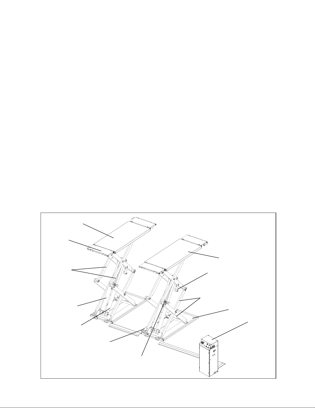
As shown in figure 2, the lift is composed of two platforms: P1 (1) and P2 (2) each equipped with the
drive-on/off ramps (3) which can be locked to the platforms as extensions, anchored to the ground by
means of bases (4).
Platforms are linked to the base by means of a scissor lifting system.
The lifting system of each platform is composed of N.4 arms: two inferior (5) and two superior (6),
and a couple of cylinders: master (7) and slave (8). The mechanical safety (9) is built on each runway
and can be locked and released by means of the air cylinder.
Motion is transmitted by a lever system, from the cylinders to the lever (10).
Lowering and lifting are carried out by means of a control unit (11), placed next to the lift.
Two limit switches are installed on the P2 base: one for the top position and one for the safety height,
protected by a cover (12).
Figure 1 - LIFT
REV. 01 2012 8 / 30
Page 8

4.2 OPERATION
Platform lifting is carried out by the hydraulic unit which acts upon the cylinders.
The platforms are raised simultaneously owing cross feeding of the hydraulic cylinders.
Lowering, even though electrically controlled, is carried out by the weight of both the platforms and
the load lifted.
The hydraulic system is protected by a max pressure valve thus preventing pressure from exceeding
the maximum fixed safety limit.
Whenever the lift has to be lowered to the ground and the lowering button is pressed, the lift will
stop at about 16 inches from the ground.
In this way, the operator must verify that neither persons nor objects are within the safety area.
If so, the final lowering button can be pressed and the lift will be completely lowered. A beep sound
is heard during the last travel.
REV. 01 2012 9 / 30
Page 9

CHAPTER 5 - TECHNICAL SPECIFICATION
5.1 SIZE AND MAIN FEATURES (ref. Figure 2)
C
APACITY
Maximum lifting height 74" (6' 2")
Minimum height of lift 4 3/8"
Length of the platform 56 ¼"
Width of platforms 23 ½"
Width between platforms Adjustable up to 31"
Overall length 78"
Maximum overall width 78 ½"
Lifting time 50 s
Lowering time 50 s
Noise level 70 dB(A)/1m
Total weight of the lift 2,300 LBS.
Working temperature
5.2 ELECTRIC MOTOR
7,000 LBS.
14 °F y 104 °F
Voltage 230V/220V-1Ph
Power 2.2 KW
N° Poles 2
Speed 2800 rpm
Motor enclosure type B14
Insulation class IP 54
Motor connection must be carried out referring to the attached wiring diagrams (Fig. 5).
The motor direction of rotation is shown in the label placed on the motor.
Before use of the lift, make sure to check if the motor specification shown in the nameplate of the
motor conforms to the local electric supply.
If there is over 10% fluctuation on the electrical power supplyˈit is suggested to use the voltage
stabilizer to protect the electrical components and system from failure.
5.3 PUMP
Type Gear
Flow rate 2.1 cm3/g 4.8 cm3/g
Continuous working pressure 210 bar – 230 bar
Peak pressure 250 bar
REV. 01 2012 10 / 30
Page 10

Figure 2 – LAYOUT
REV. 01 2012 11 / 30
Page 11

5.4 HYDRAULIC POWER UNIT
Figure 3 – HYDRAULIC POWER UNIT
Emergency
hand pump
Lowering
solenoid valve
Safety solenoid
valves
Motor
Leveling cocks
Pressure gauge
5.5 OIL
Use wear proof oil for hydraulic drive, in conformity with ISO 6743/4 rules (HM class).
T
EST STANDARDS FEATURES VALUE
ASTM D 1298
Density 20°C 0.8 kg/l
ASTM D 445 Viscosity 40°C 32 cSt
ASTM D 445 Viscosity 100°C 5.43 cSt
ASTM D 2270 Viscosity index 104 N°
ASTM D 97 Pour point
a 30 °C
ASTM D 92 Flash point 215 °C
ASTM D 644 Neutralization number 0.5 mg KOH/g
C
HANGE HYDRAULIC OIL AT 1 YEAR INTERVALS
REV. 01 2012 12 / 30
Page 12

Figure 4 - HYDRAULIC PLAN
1a P1 master cylinder 5b Leveling cock – P2
1b P2 master cylinder 6 Lowering speed control
2a P1 slave cylinder 7 Maximum pressure valve
2b P2 slave cylinder 8 Oil filter
3a Parachute valve – P1 (optional) 9 Gear pump
3b Parachute valve – P2 (optional) 10 Motor
4a Ssafety solenoid valve – P1 11 Non return valve
4b Safety solenoid valve – P2 12 Pressure gauge
4c Lowering solenoid valve 13 Emergency hand pump
5a Leveling cock – P1
REV. 01 2012 13 / 30
Page 13

Figure 5b – ELECTRICAL PLAN (220V/230V-1PH)
[EODFN
[EOXH
[\HOORZJUHHQ
:$
$
[EODFN
[EOXH
[\HOORZJUHHQ
)
)
$
$
ᙕڌ
Function
indicator
QF Power switch QV Safety air valve
M Motor 2.2KW 1PH SB1 Lifting button
ST Thermal relay SB2 Lowering/final lowering button
T Transformer 80VA SB3 Safety engaging button
KM Contactor DC JD Beeper
YV1 Lowering solenoid valve SQ1 Top limit switch
YV2 Safety solenoid valve – P1 SQ2 Safety height limit switch
YV3 Safety solenoid valve – P2
REV. 01 2012 14 / 30
Page 14
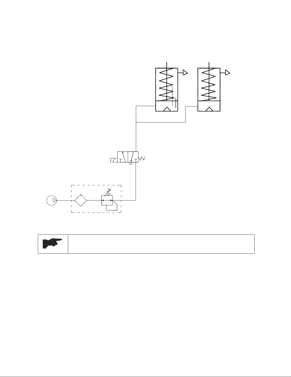
Figure. 6 – PNEUMATIC PLAN
Compressor
Lubricator
P2 safety cylinder
Safety air valve
P1 safety cylinder
Pressure regulator 7 bar
Lubricator/pressure regulator can be supplied by the manufacturer on
request.
The pressure in the pneumatic line must be kept around 6bar – 8 bar.
REV. 01 2012 15 / 30
Page 15

CHAPTER 6 - SAFETY
Read this chapter carefully and completely because it contains important information for the safety of
the operator and the person in charge of maintenance.
The lift has been designed and built for lifting vehicles and making them stand
above level in a closed area. Any other use is forbidden.
The manufacturer is not liable for possible damages to people, vehicles or
objects resulting from an improper or unauthorized use of the lift.
For the safety of the operator and anyone near the lift, a safety area of at least 3 ft. around the lift
must be vacated during lifting and lowering. The lift must be operated only from the operator’s
control site in this safety area.
Operator’s presence under the vehicle, during working, is only admitted when the vehicle is lifted and
platforms are not running.
Never use the lift when safety devices are off-line. People, the lift, and the
vehicles lifted can be seriously damaged if these instructions are not followed.
6.1 GENERAL WARNINGS
The operator and the person in charge of maintenance must follow accident-prevention laws and rules
in force in the country where the lift is installed
They also must carry out the following:
x neither remove nor disconnect hydraulic, electric or other safety devices;
x carefully follow the safety indications applied on the machine and included in the manual;
x observe the safety area during lifting;
x be sure the motor of the vehicle is off, the gear engaged and the parking brake put on;
x be sure only authorized vehicles are lifted without exceeding the maximum lifting capacity;
x Verify that no one is on the platforms during lifting or standing.
6.2 RISKS DURING VEHICLE LIFTING
To avoid overloading and possible breaking, the following safety devices have been used:
x a maximum pressure valve placed inside the hydraulic unit to prevent excessive weight.
x a special design of the hydraulic system, in case of pipeline failure, to prevent sudden lift
lowering.
The maximum pressure valve has been preset by the manufacturer to a proper
pressure. DO NOT try to adjust it to overrun the rated lifting capacity.
6.3 RISKS FOR PEOPLE
All the possible risks due to improper use of the lift, are described in this section.
REV. 01 2012 16 / 30
Page 16

6.4 PERSONNEL CRUSHING RISKS
During lowering of runways and vehicles, personnel must not be within the area covered by the
lowering trajectory. The operator must be sure no one is in danger before operating the lift.
Fig. 7a
Fig. 7b
Fig. 7c
6.5 BUMPING RISK
When the lift is stopped at relatively low height for
working, the risk of bumping against projecting parts
occurs.
Fig. 8
6.6 RISK OF THE VEHICLE FALLING FROM THE LIFT
Vehicle falling from the lift can be caused when the vehicle is improperly placed on platforms, and
when its dimensions are incompatible with the lift or by excessive movement of the vehicle.
In this case, immediately move away from the working area.
Fig.9a
Fig. 9b
Fig. 9c
6.7 SLIPPING RISKS
The risk of slipping can be caused by oil or dirt on the floor near
the lift.
Fig. 10
REV. 01 2012 17 / 30
Page 17

Keep the area under and around the lift clean. Remove all oil spills.
6.8 ELECTROCUTION RISKS
Avoid use of water, steam, and solvent, varnish jets in the lift area where electric cables are placed
and, in particular, next to the electric panel.
6.9 RISKS RESULTING FROM IMPROPER LIGHTING
Make sure all areas next to the lift are well and uniformly lit, according to local regulations.
6.10 RISKS OF BREAKING COMPONENTS DURING OPERATION
Materials and procedures suitable for the designed parameters of the lift
have been used by the manufacturer to build a safe and reliable product.
Operate the lift only for the use it has been designed for and follow the
maintenance schedule shown in the chapter “Maintenance”.
Fig. 11
6.11 RISKS FOR UNAUTHORIZED USES
The presence of unauthorized persons next to the lift and on the
platforms is strictly forbidden during lifting as well as when the vehicle
has been already lifted
Any use of the lift other than that herein specified can cause serious injury to
people in close proximity of the machine.
Fig. 12
REV. 01 2012 18 / 30
Page 18

CHAPTER 7 - INSTALLATION
r
a
Only skilled technicians, appointed by the manufacturer, or by authorized
dealers, must be allowed to carry out installation. Serious damage to people and
to the lift can be caused if installations are made by unskilled personnel.
Before carrying out any operations, remember to insert the safety piece of wood
between the lower booms and the base frame.
7.1 CHECKING FOR ROOM SUITABILITY
The lift has been designed to be used in covered and sheltered places free of overhead obstructions.
The place of installation must not be next to washing areas, painting workbenches, solvent or varnish
deposits. Installation near rooms where a dangerous situation of explosion can occur, is strictly
forbidden. The relevant standards of the local Health and Safety at Work regulations, for instance,
with respect to minimum distance to wall or other equipment, escapes and the like, must be observed.
7.2 LIGHTING
Lighting must be carried out according to the effective regulations of the place of installation. All
areas next to the lift must be well and uniformly lit.
7.3 INSTALLATION SURFACE
The lift must be placed on a 425 concrete floor with FEB 215 K reinforcement, minimum 6 inches
thick, and in conformity with local regulations.
If a floor covering with the above mentioned requirements is not available, a foundation plate is
needed, or some fixing points should be used for fixing areas at least having sufficient size and
thickness (made of concrete of the same quality, as shown).
The surface where the lift has to be installed must be even and level in all directions. An inclination
not higher than 1 inch in drive-on lift direction and ½ inch cross-wise can be balanced with leveling
wedges.
For installation on raised surface, the compliance with the maximum carrying capacity of the surface
is recommended.
The new concrete must be adequately cured by at least 21 days minimum.
7.4 RUNWAY ASSEMBLY AND CONTROL UNIT POSITIONING
Unauthorized persons are not allowed to enter during assembly...
x Now locate the lift according to the figure 2, use a carpenters chalk line to layout a grid fo
the base locations according to the drive-on direction of the lift.
x Transport platforms to the installation site by using hoisting means with load capacity of at
least 1,100 LBS. To prevent the platform from dropping during transport, it should be lifted
according to its center of gravity.
x Alw
ys raise platforms by holding them on the underside of the bases.
REV. 01 2012 19 / 30
Page 19

x Place the control unit in the position provided for.
7.5 HYDRAULIC SYSTEM CONNECTION (ref. fig. 13)
x Open the front cover of the control unit.
x Connect hydraulic hose to the fittings referring to the letters shown on them.
x Tighten thoroughly.
Make sure that the hoses are clear of any moving parts. Make sure to keep the
hoses and fittings clean from dust. Failure to do so may result in hydraulic
line failure which may result in damage or personal harm.
Figure 13 – HYDRAULIC CONNECTION
P1
P2
REV. 01 2012 20 / 30
Page 20

7.6 MAKE THE ELECTRICAL HOOKUP TO CONTROL UNIT
The hookup work must be carried out by a qualified electrician.
Make sure that the power supply is right.
Make sure the connection of the phases is right. Improper electrical hook-up
can damage the motor and will not be covered under warranty.
DO NOT run the hydraulic unit without oil. Damage to pump can occur.
The control unit must be kept dry. Damage to power unit caused by water or
other liquids such as detergents, acid etc., is not covered under warranty.
x Make the electric hookup to the hydraulic power unit referring to the wiring diagram in figure
5 using included electric cable.
x Make sure the connection of the phases is right and the lift is grounded.
7.7 FEEDING OIL AND BLEEDING
During this procedure, observe all operating components and check for proper
installation and adjustment.
DO NOT attempt to raise vehicle until a thorough operation check has been
completed.
7.7.1 CHECK
x Inspect all pins and bolts to insure proper mounting
x Make sure the electrical system feeding voltage is equal to that specified in the nameplate on
the motor
x Make sure the electric connections are in compliant with the wiring diagrams (figure 5)
x Make sure this is no leakage or blow-up in the hydraulic line and pneumatic line
x Make sure the lift is connected to the ground
7.7.2 START
x Be sure the working area is free from people and objects
x Verify that the control unit is powered
x Pour oil in the tank (about 16 liters more than one time)
x Feed the lift by the power switch
x Verify that the motor direction of rotation is that shown on the label by pushing the lifting
button. IF MOTOR GETS HOT OR SOUNDS PECULIAR, STOP IMMEDIATELY AND
RECHECK THE ELECTRIC CONNECTIONS
7.7.3 FEEDING OIL
x Turn on the leveling cocks (fig.14 - 1);
x Push the lifting button (fig. 15 – 1) to feed the oil into the cylinders for approximately 30
seconds;
x Turn off the leveling cocks;
REV. 01 2012 21 / 30
Page 21

7.7.4 BLEEDING THE HYDRAULIC LINE
g
Do not install the safety height limit switch before the bleeding procedure.
ATTENTION: Refill the oil if there is not enough during this procedure.
After adjusting the level of the lift, reset to ordinary operating conditions.
To lower the lift, be sure to raise the lift a little bit by pushing the lifting button
to release the safeties and then lower the lift by pressing the lowering button.
x Raise the lift by pressing the lifting button until the cylinder bottoms out and stops;
x Press the lowering button (fig. 15 – 2) with the leveling cocks turned on;
x Hold the lowering button to lower the lift completely;
x Raise the lift to the top position with the levelling cocks off;
x Lower the lift completely with the levelling cocks on;
x Follow this procedure and repeat raising and lowering the lift at least 5 times to bleed all the
air out of the cylinders.
1
1
2
.14
Fi
Fig. 15
7.7.5 PLATFORM LEVELING
If the platforms aren’t leveled (one of the two platforms is lower than the another one), follow these
instructions:
x Turn on the leveling cock of the lower platform
x Feather-push the lifting button until this platform is in the same height as another.
x Turn off this leveling cock after leveling.
7.8 ANCHORING THE LIFT
x Raise the platforms approximately 3 feet above the ground.
x Using the base frames as guide, drill each hole in the concrete approximately 5 inches deep
with the rotary hammer drill
D.16. To assure full holding power, do not ream the hole or allow
drill to wobble.
x After drilling, remove dust thoroughly from each hole using compressed air or wire brush.
x Assemble the washers and nuts on the anchors then tap into each hole with a hammer until the
washer rests against the base plate. Be sure if shimming is required, enough threads are left
exposed.
x If shimming is required, insert the shims as necessary around the anchor bolts.
REV. 01 2012 22 / 30
Page 22

x With the shims and the supplied anchor bolts in place, tighten by securing the nut to the base.
7.9 ADJUSTMENT OF LIMIT SWITCHES (ref. fig. 16)
Only skilled personnel must be allowed to carry out this operation.
An improper adjustment of limit switches could cause damages to the lift,
objects and people.
Limit switches must be adjusted during the installation of the lift
This lift is equipped with 2 proximity switches for the top position and the safety height position.
Both are to be mounted on the P2 base and can be activated by the slider when it passes by.
If limit switches were not functioning properly, it’s possible to adjust them in the following way:
7.9.1 ADJUSTMENT OF TOP LIMIT SWITCH (fig.16-1)
x Place the lift at a height of 6 feet;
x Loosen the nuts (3) of the limit switch and adjust it at the desired height;
x Tighten the nuts after adjustment.
7.9.2 ADJUSTMENT OF SAFETY HEIGHT LIMIT SWITCH (fig.16-1)
x Place the lift at a height of 1 foot;
x Loosen the nuts (3) of the limit switch and adjust it at the desired height;
x Tighten the nuts after adjustment.
After adjustment of the switches, make sure to fix the switch protection (fig.16-
4) on the base. Failure to do so can damage the switches.
Figure 16 – LIMIT SWITCHES
4 3
1
2
7.10 LOADLESS CHECK
Carry out two or three complete cycles of lowering and lifting and check:
x proper oil level in the tank
x no leakage and blow-by in hydraulic line
x cylinders for proper operation
REV. 01 2012 23 / 30
Page 23

x the level of the platforms
x the lift for reaching its maximum height
x the limit switches for proper operation
x the horn/signaling light for proper operation during the final travel
7.11 CHECKING WITH LOAD
WARNING: please follow the instructions in the following paragraph carefully
to avoid damaging the lift.
Before carrying out the checks with load, inspect the machine and check bolts and nuts for proper
tightening.
x repeat checks provided for by 7.10 section with the vehicle loaded
x if the platforms weren’t leveled, repeat the 7.7 section
REV. 01 2012 24 / 30
Page 24

CHAPTER 8 - OPERATION AND USE
Never operate the lift with any person or equipment below.
Never exceed the rate lifting capacity.
If an anchor bolts become loose or any component of the lift is found to be
defective, DO NOT USE THE LIFT until repairs are made.
Do not permit the electric control unit to get wet!
8.1 CONTROLS
Figure 17 - CONTROL PANEL
3
4
2
5
1
6
Controls for operating the lift are:
POWER SWITCH (1)
The power switch can be set in two positions:
¾ 0 position: the lift electric circuit is not powered; the switch can be padlocked to prevent the
use of the lift.
¾ 1 position: the main electric circuit is powered.
FUNCTION
INDICATOR (2)
¾ When ON lights, it shows that the electric circuit is powered.
¾ When
¾ When
¾ When
¾ When
¾ When
lights, it shows that the top limit switch is working.
lights, it shows that the safety height limit switch is working.
lights, it shows that the power unit is working.
lights, it shows that the lift has started the final lowering.
lights, it shows the electric circuit is connected incorrectly or has a malfunction.
BEEPER (3)
LIFTING BUTTON (4)
¾ When pressed, the electric circuit for the lift operates the motor and hydraulic circuit to raise
REV. 01 2012 25 / 30
Page 25

the lift
SAFETY ENGAGING BUTTON (5)
¾ When pressed, the lowering solenoid valve operates the hydraulic circuit to lower the lift to
engage the nearest mechanical safeties.
LOWERING/FINAL LOWRING BUTTON (6)
¾ When pressed, the lift begins to descend to the safety height (about 1 ft.).
¾ When pressed with the lift at the safety height, the lift is lowered to the ground. A beep
sound is heard during the last travel.
Be sure the safety area is free from people and objects during the final travel
Lift operation can be summarized into four steps:
8.2 LIFTING
x Place the vehicle at the center of the platform and lock the extensions;
x Check to make sure that the vehicle is secured;
x Place pads under the positions indicated for lifting, by the motor vehicle’s manufacturer;
x Set the power switch to 1 position
x Push the lifting button to lift the vehicle to the required height;
x Rest the lift in standing position by pushing the safety engaging button to engage the safeties.
8.2 LOWERING
x Raise the lift a little bit to release the safeties
x Press the lowering button;
x The lift will descend, under its own weight and car’s, to the safety height of 1 ft.;
x Be sure the safety area is free of people and objects;
x Press the lowering button again until the lift is lowered to ground completely. A beep sound is
heard during the last travel.
8.3 MANUAL EMERGENCY LOWERING
In case of an emergency (power failure), the lift can be lowered manually to its initial position as
follows referring to figure 18:
Fig. 18
x Padlock the power switch;
x Open the front cover of the control unit;
1
x Open the safety solenoid valves by turning the
emergency screws (2) counter clockwise;
x Operate the emergency hand pump (1) to raise the lift
3
a little bit to clear the mechanical safety locks;
x Hold the emergency button on the safety air valve
located in the control unit;
x Open the lowering solenoid valve by turning the
2
REV. 01 2012 26 / 30
Page 26

emergency screw (3) counter clockwise to lower the lift.
x Retighten the emergency screw clockwise after lowering the lift completely.
Tip: when a mechanical safety is released, it is advised to use a board to put
between the safety pawl and the rack to avoid it from engaging. In this case, you
do not need to press the emergency button continuously.
Tightening or loosening the screw can reduce or increase the lowering speed.
After manual lowering of the lift, reset it to ordinary operating conditions. The
lift cannot be lifted if the solenoid valves are opened.
REV. 01 2012 27 / 30
Page 27

CHAPTER 9 - MAINTENANCE
Only trained personnel who know how the lift works must be allowed to service
the lift.
To properly service the lift, the following has to be carried out:
x use only genuine spare parts as well as equipment suitable for the work required;
x follow the scheduled maintenance and check periods shown in the manual;
x discover the reason for possible failures such as too much noise, overheating, oil blow-by,
etc.
Refer to documents supplied by the dealer to carry out maintenance:
o functional drawing of the electric and hydraulic equipment
o exploded views with all data necessary for spare parts ordering
o list of possible faults and relevant solutions.
Before carrying out any maintenance or repair on the lift, disconnect the power
supply, padlock the general switch and keep the key in a safe place to prevent
unauthorized persons from switching on or operating the lift
9.1 ORDINARY MAINTENANCE
The lift has to be properly cleaned at least once a month using self-cleaning clothes. Lubricate all
pivot pins at least once a week.
The use of water or inflammable liquid is strictly forbidden
Be sure the rod of the hydraulic cylinders is always clean and not damaged since this may result in
leakage from seals and lead to possible malfunctions.
9.2 PERIODIC MAINTENANCE
Hydraulic circuit check oil tank level; refill with oil, if needed;
check the circuit for oil leakage.
Check seals for proper conditions and replace them
if necessary;
Every 3 months
Every 6 months Oil Check oil for contamination or ageing.
Every 12 months
Foundation bolts check bolts for proper tightening
Hydraulic pump verify that no noise changes take place in the pump
of the control desk when running and check fixing
bolts for proper tightening
Safety system check safety devices for proper operation
Contaminated oil is the main reason for failure of
valves and shorter life of gear pumps
General check verify that all components and mechanisms are not
damaged
Electrical system a check of the electrical system to verify that control
desk motor, limit switches and control panel operate
properly must be carried out by skilled electricians
REV. 01 2012 28 / 30
Page 28

CHAPTER 10 - TROUBLESHOOTING
A list of possible problems and solutions are given below:
ROUBLE: POSSIBLE CAUSE: SOLUTION:
T
The main switch is not turned on Turn the switch on
The lift does not work
The lift does not raise
when the lifting button
is pressed
The lift does not lower
when the lowering
button is pressed
The lift does not stop at
the safety height
There is no power
The electrical wires are
disconnected
Fuses are blown Replace
One of limit switches is faulty. Check the switch and relevant
The motor direction of rotation is
not correct
The oil in the hydraulic unit is not
sufficient
The lifting button is faulty
The lowering solenoid valve does
not close
The emergency screw of lowering
valve does not close
The suction pump filter is dirty Check and clean if needed
The motor does not operate properly
and does not release the mechanical
safeties
The lift goes up instead of going
down
-Because safety air valve is faulty Replace air valve
-Because the air does not reach the
circuit
-Because electric board is faulty Replace electric board
The lowering solenoid valve does
not discharge
The lowering solenoid valve is not
operating
The lowering button is faulty
The safety height limit switch is not
adjusted correctly or it is faulty
The electric board is not operating Replace electric board
The motor does not operate properly
and does not release the mechanical
safeties
Check power and restore if
necessary
Replace
connection for proper operation.
Replace, if needed.
Interchange the phases on the main
switch
Add some hydraulic oil
Check UP button and connection
for proper operation. Replace, if
needed
Check and clean, if dirty, or replace,
if faulty
Retighten the screw
Check the motor
Verify the compressor and air hose
ability
Verify if it is powered and check
the magneto for damages (replace if
disconnected or burnt)
Verify if it is powered and check
the magneto for damages (replace if
disconnected or burnt)
Check the lowering button and
connection for proper operation.
Replace, if needed
Adjust or change the limit switch
Check the motor
REV. 01 2012 29 / 30
Page 29

The lowering button is faulty
The electric board is faulty Replace electric board
The lift isn’t raising
synchronous
Presence of air or dripping in the
hydraulic circuit
The cylinder gaskets are damaged Check and replace if necessary
The lifting capacity is
not sufficient
The oil in the tank is not enough Fill oil in the tank
The pump is faulty
The pressure valve is not adjusted
correctly
The lift does not lift or
lower smoothly
The motor does not stop
Leakages or presence of air in the
hydraulic circuit
The top limit switch does not work Check the limit switch and replace
when reaching it
maximum height
The lift does not lift or
lower smoothly
Leakages or presence of air in the
hydraulic circuit
The pump filter is dirty. Check and clean if needed.
The pump suction is blown Check the seal and replace if needed
Check the lowering button and
connection for proper operation.
Replace, if needed
Bleed the hydraulic circuit
Check the pump and replace if
necessary
Adjust it correctly
Bleed the hydraulic system
if needed
Bleed the hydraulic system
REV. 01 2012 30 / 30
 Loading...