

Page 1

Page 2

CONTENTS
Product Features and Specifications .................................................3
Installation Requirement ................................................................5
Steps of Installation ......................................................................6
Exploded View ............................................................................32
Test Run ............................................................................. ...... 35
Operation Instruction ..................................................................37
Maintenance ............................................. .................................37
Trouble Shooting ........................................................................38
Parts List ........................... ...................................... .................39
Page 3

I. PRODUCT FEATURES AND SPECIFICATIONS
CLEAR-FLOOR DIRECT-DRIVED MODEL FEATURES
Model PV-15P (See Fig. 1)
· Direct-drive design, minimizes the lift wear parts and breakdown ratio
· Dual hydraulic cylinders, designed and made on ANSI standards, utilizing NOK oil seal
in the cylinders
· Self- lubricating UHMW Polyethylene sliders and bronze bushings
· Single-point safety release with dual safety design
. Clear-floor design, provides unobstructed floor use
. Overhead safety shut-off device prevents vehicle damage
. Standard adjustable heights accommodates different ceiling heights
MODEL PV-15 SPECIFICATIONS
Fig. 1
Model Style
PV-15P
Clear-floor
Direct-drive
Lifting
Capacity
6.8 T
15,000lbs
Lifting
Time
72S
Lifting Height Overall Height
1872-2142mm
73 3/4”–84 3 /8”
3812/4192/4497mm
150”/165”/177”
- 3 -
Overall
Width
3829mm
150 3/4”
Width
Between
columns
3137mm
123 1/2”
Minimum
Pad Height
for
stackable
adapter
145
5 3/4”
Motor
4.0HP
Page 4
”
”
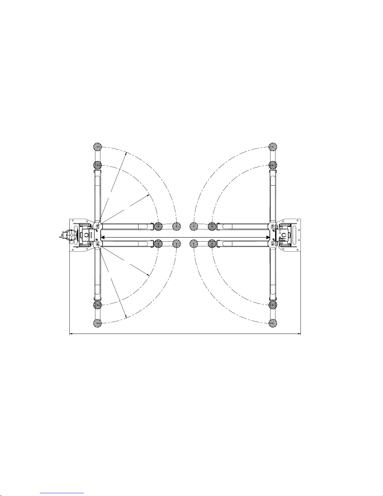
Arm Swings View For Model PV-15P
63 ¼
41 1/8”
109 ¾”
41 1/8”
63 ¼”
150 ¾
Fig. 2
- 4 -
Page 5

II. INSTALLATION REQUIREMENT
A. TOOLS REQUIRED
Rotary Hammer Drill (19mm / ¾”) Carpenter’s Chalk
Hammer Screw Sets
Level Tape Measure (25ft)
Crescent Wrench
(12") Pliers
Wrench set:(10
19
Ratchet Spanner With Socket (28mm)
#
、13#、14#、15#、17
#
、24#、27#、30
#
)
#
Lock Wrench
Socket Head Wrench (3
#
, 5#, 8#)
Fig.3
- 5 -
Page 6
B. CONCRETE SPECIFICATIONS (See Fig. 4)
Concrete specifications must be adhered to the following specification.
Failure to do so may result in lift and/or vehicle falling.
1. Concrete must be thickness 6 inches minimum and without reinforcing steel bars, and
must be totally dry before lift installation.
2. Concrete must be in good condition and must have a test strength 3,500psi
(250kg/cm²) minimum.
3. Floors must be level with no cracks or holes.
C. POWER SUPPLY
The electrical source must be 3HP minimum. The source cable size must be 2.5mm² and
in good condition of contacting with floor.
Fig.4
III. INSTALLATION STEPS
A. Location of installation
Check the installation location (concrete, layout, space size etc.) is suitable for lift
installation.
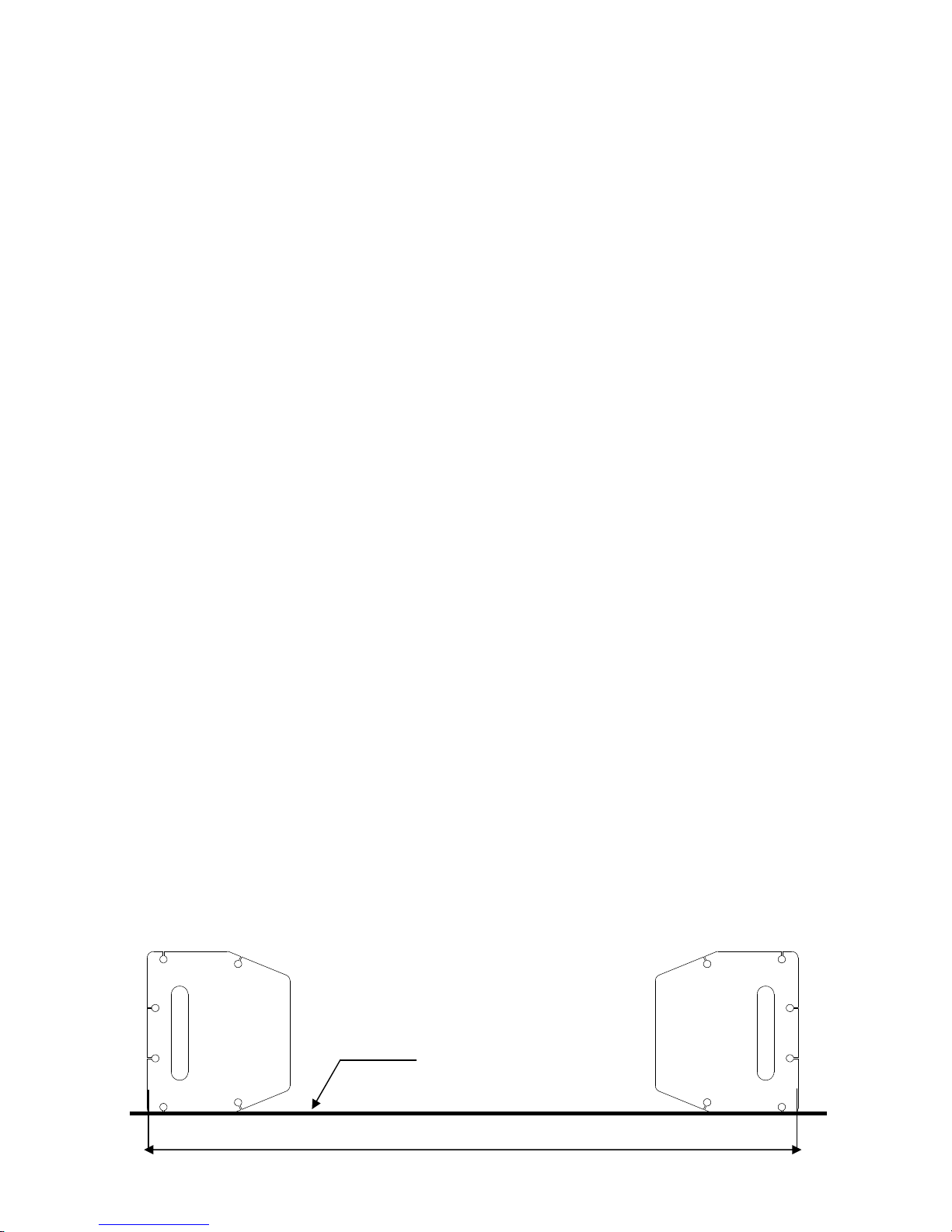
B. Use a carpenter’s chalk line to establish installation layout of the base plate
Model PV-15P
(See Fig. 5)
Chalk Line
150 ¾”
Fig. 5
- 6 -
Page 7
C. Check the parts before assembly.
1. Packaged lift, hydraulic power unit and parts box (
See Fig. 6).
Fig. 6
2. Move the lift aside with a fork lift or hoist, and open the outer packing carefully
(See Fig. 7).
Shipment Parts list
Serial No.
Fig. 7
3. Remove aside the top connecting assembly. (See Fig. 8).
Top Connecting
Assembly
Fig. 8
- 7 -
Page 8

4. Lift the upper column with a fork lift or hoist, loosen the bolts on the upper package
stand, take off the upper outer column, then take out the parts in the inner column
Fig. 9).
(See
5. Lift the lower column with a fork lift or hoist, take down the package stand, then take off
Fig. 9
the lower outer column, take out the parts in the inner column
(See Fig. 10).
6. Move aside the parts and check the parts according to the shipment parts list
(See Fig. 11).
Fig. 10
Fig. 11
- 8 -
Page 9
7. Open the carton of parts and check the parts according to parts box list (See Fig. 12).
8. Check the parts in the part bag #1 according to parts bag list
Fig. 12
(See Fig. 13).
Fig. 13
9. Check the parts in the parts bag #2 according to parts bag list
(See Fig. 14).
Fig. 14
- 9 -
Page 10

D. Install parts on the extension columns
(See Fig. 15).
Fig. 15
- 10 -
Page 11

E. Install hydraulic cylinders
Off
Connect the extended straight fitting and 90° fitting, and then install the cylinder
inside the carriages
(See Fig. 16).
side column
Power side column
The direction of fitting
Fig. 16
- 11 -
Page 12

F. Install columns
Lay down the two columns on the installation site parallel, position the power side column
according to the actual installation site. Usually, it is suggested to install power side column
on the front-right side from which vehicles are driven to the lift. This lift is designed with
2-Section columns. Adjust the height according to the ceiling height and connect the inner
and outer columns.
1. When the ceiling height is over 4500mm (177 1/8”), connect the outer columns with the
lower hole
(See Fig. 17).
Fig. 17 High setting
- 12 -
Page 13

2. When the ceiling height is between 4200mm (165 3/8”) to 4500mm (177 1/8”), connect
the outer columns with the middle hole
(See Fig.18).
Fig. 18 Low setting
- 13 -
Page 14

3. When the ceiling height is less than 4200mm (165 3/8”), connect the outer columns with
the upper hole. For this height setting you will need to purchase the shorter cables
(part#217063)
(See Fig.19).
Fig. 19 Special low setting
- 14 -
Page 15

G. Position columns (Do not drill anchor holes at this time)
Position the power side column in its designated place. Place the off side column
approximately 12 1/2” from the power side column. Install the overhead top beam. Once
the overhead top beam is in place and secured, the anchor holes can be drilled.
Fig.20 & 21).
(See
Adjusting with
the shims
37
Drilling
Width between columns: 123 1/2”
Overall width:150 3/4"
Cleaning
Bolting
Fig. 20
- 15 -
Page 16

H. Install overhead top beam
1. With help of the hook on the top beam, put one side of the top beam on top of the extension
column and connect the top beam to the extension column with bolts, tighten the bolts.
Then assemble the connecting bracket
(See Fig. 21).
Hook on to the
extension columns
Tighten the bolts
Fig. 21
- 16 -
Page 17

2. Assemble overhead top beam, tighten the columns anchor bolts
(See Fig. 22).
Tighten
Fig. 22
- 17 -
Page 18

I. Installing the limit switch control bar and limit switch (See Fig. 23).
NC: Normal contact
Limit Switch connected
with cable
Fig. 23
Loosen Screw on the
Drive Rod for
adjustment, Tighten the
screw after adjustment
Adjust Drive Rod on
Limit Switch
65
Fig. 23
- 18 -
Page 19

J. Install safety device (See Fig. 24 & Fig. 25).
Fig. 24 Power side safety device
Fig. 25 Off side safety device
- 19 -
Page 20

K. Lift the carriages up by hand and lock them at the same level (See Fig. 26).
Fig. 26
- 20 -
Page 21

L. Install cables
1. High setting cable connection. Suitable for ceiling height over 4500mm (177 1/8”).
1.1 Take off the carriages pla stic cover, the cable passes through from th e bottom of the
carriages and is pulled out from the opening of the carriages, then screw the two cable
(See Fig. 27).
nuts
Tighten
Cable connecting
direction
Fig. 27
- 21 -
Cable connecting
direction
Page 22

1.2 Connecting cable for high setting (See Fig. 28)
Cable 2
High setting
Cable 1
95
96
Cable 2
Fig. 28
94
- 22 -
Page 23

2. Low setting cable connection. Suitable for ceiling height between 4200mm (165
3/8”) to 4500mm (177 1/8”)
(See Fig. 29).
Low Setting
Cable 1 Cable 2
Cable 2
Fig. 29
- 23 -
Page 24

3. Special low setting cable connection. Suitable for ceiling heights less than 4200mm
(165 3/8”)
(See Fig. 30). This setting needs the optional short cable.
Special low setting
Cable 2
Cable 1
Cable 2
96
99
94
Fig. 30
- 24 -
Page 25

M. Install power unit (See Fig. 31)
Fig. 31
- 25 -
Page 26

N. Install oil hose.
1. High setting and low setting oil hose connection (See Fig. 32)
Limit switch wire
Oil hose
Oil hose and wire
pass through the
support bracket
88
Fig. 32
Oil hose passes
through the wire tube
on top beam
Oil hose connected
with T-fitting
Oil hose connected
with 90° fitting
- 26 -
Page 27

O. Install the safety cable.
Install safety cable from offside safety assembly to power side safety assy. , pass through
the top beam
(See Fig. 33).
Safety cable
Safety cable passes
through the small pulley
bracket
Install safety cable
from offside safety
assembly first
Safety cable connected with
the power side safety
assembly
Fig. 33
- 27 -
Page 28

P. Install retainers
(See Fig. 34).
Install retainer to fix
the oil hose.
Car in direction
Fig. 34
- 28 -
Page 29

Q. Install the lifting arms (See Fig. 35)
L
Lower the carriages down to the lowest position. Then use the 8# socket head wrench to
loosen the bolt
Fig.37)
socket bolts on the arm locks
. Adjust the moon gear and arm locks so they mesh together, then tigh ten the
(See Fig.36). Adjust the arm lock in the direction of the arrow (See
Fig. 35
Moon Gear
(See Fig.38).
Loose the Socket Bolt
Use the 8
loose the Socket Bolt
#
Socket Head Wrench to
Fig. 36
Arm lock
Adjust moon gear and arm lock
Locking the bolts after moon
gear and arm lock engage well
ocking the bolts
Fig. 37
Fig. 38
- 29 -
Page 30

R. Tighten all of the hydraulic fittings, and fill the reservoir with hydraulic oil (App. 4 gal.).
Note: For the best motor performance, use only a #46 series hydraulic oil.
S. Install electrical system
Connect the power source on the data plate of Power Unit.
Note: 1. For safety purposes, the power wiring must contact a sufficient ground.
ATLAS single phase motor
1. Remove the line of connecting terminal 4# on the control button and L1 on the AC
contactor
(See Fig. 39).
2. Circuit diagram
(See Fig. 40)
A1
L1
Remove this line
before connecting the
Limit Switch
3#
4#
Fig. 39
3. Connection step
(See Fig. 41)
a. Connect the two power supply lines (fire wire L and zero wire N) to terminals on the AC
- 30 -
Limit switch
Fig. 40
Control button
Page 31

contactor marked L1, L2.
b. Connect wire 12# on the limit switch with te rminal L1 on the AC contactor; Connect
wire 11# with terminal 4# on the control button.
Limit switch wire
Power wire
Fig. 41
4. Connection wire
(See Fig. 42)
L 12# 11#
L1 L2 N
A1
4#
3#
Control button
Fig. 42
Fig. 42
Limit switch
- 31 -
Page 32

III. EXPLODED VIEW
Model:PV-15P
20
Fig. 43
- 32 -
Page 33

Cylinders
Fig. 44
ATLAS Manual power unit
220V/50HZ, Single Phase
(Fig. 50)
Fig. 45
- 33 -
Page 34

Illustration of the hydraulic valve for ATLAS hydraulic power unit
a. PEAK manual power unit, 220V/50HZ, Single phase (See Fig. 51)
Oil return port
Protective ring
Release valve
Oil Outlet
Handle of Release
valve
Relief valve
Throttle valve
Check valve
Fig. 46
- 34 -
Page 35

Ⅴ. TEST RUN
1. Adjust synchronizing cable (See Fig. 47)
Spanner to hold the cable fitting. Meanwhile,
Use
use ratchet spanner to tighten the cable nut.
Make sure two cables have the same tension
Cable nut
so the two carriages locks click at the same time.
Fig. 47
Replace the plastic covers on the carriages.
If the carriage does not synchronize when lifting, please tighten the cable nut.
2. Adjust the safety cable
Lift the carriages and lock them at the same height, strain the safety cable and then
release a little, and then tighten the cable nuts. Check for proper operation.
Bleeding plug
3. Exhaust air
This hydraulic system is designed to bleed air by loosing
the bleeding plug. Lift the carriages to about 12”
and loosen the bleeding plugs. Lower the lift until fluid
comes out og the bleeding plugs. Retighten bleeding plugs.
(See Fig. 48).
4. Adjust the lower speed
(Only for PEAK power unit)
Fig. 48
You can adjust the lowering speed of the lift if needed: Loosen the fixing nut on the
throttle valve, and then turn the throttle valve clockwise to decrease the lower speed, or
counterclockwise to increase the lower speed. Do not forget to tighten the fixing nut after
the lowering speed adjustment has been done.
Throttle Valve
Fixing Nut
Clockwise to decrease
the down speed
Fig. 49
Counterclockwise to increase
the down speed
- 35 -
Page 36

5. Test with load
After finishing the above adjustment, test run the lift with a load. Run the lift in low
position several times first, make sure the carriages raise and lower at the same time. The
safety locks should lock and release at the same time. Test run the lift to the top.
Fig. 50 Hydraulic System
- 36 -
Page 37

Ⅵ. OPERATION INSTRUCTIONS
Please read the safety tips carefully before operating the lift
To lift vehicle
1. Keep clean of site near the lift;
2. Position lift arms to the lowest posit ion;
3. To shortest lift arms;
4. Open lift arms;
5. Position vehicle between columns;
6. Move arms to the vehicle’s lifting point;
Note: The four li ft arms must at the same time contact the vehicle’s lifting point where
manufacturers recommended
7. Press the UP button until the lift pads contact underside of vehicle totally. Recheck to
make sure vehicle is secure;
8. Continue to raise the lift slowly to the desired working height, e nsuring the balance of
the vehicle;
9. Push lowering handle to lower lift onto the nearest safety lock. The vehicle is ready t o
repair.
To lower vehicle
1. Be sure clear of around and under the lift, only leaving operator in lift area;
2. Press the button of UP to raise the vehicle slightly, and then release the safety locks,
lower vehicle by pushing lowering handle.
3. Open the arms and position them to the shortest length;
4. Drive away the vehicle.
IV. MAINTENANCE SCHEDULE
Monthly:
1. Re-torque the anchor bolts to 80-100ft lbs.
2. Check all connectors, bolts and pins to insure proper mounting;
3. Lubricate cable with lubricant;
4. Make a visual inspection of all hydraulic hoses/lines for possible wear or leakage;
5. Check safety locks and make sure they are in good condition;
6. Lubricate all rollers and pins with 90wt. Gear oil or equivalent;
Note: All anchor bolts should take full torque. If any of the bolts do not tighten, DO NOT
use the lift until the bolt has been replaced.
Every six months:
1. Make a visual inspection of all moving parts for possible wear, interference or damage.
2. Check and adjust as necessary, equalizer tension of the cables to ensure level lifting.
3. Check columns for plumb.
4. Check rubber pads and replace as necessary.
5. Check the condition and function of the safety locks
- 37 -
Page 38

V. TROUBLE SHOOTING
TROUBLE CAUSE REMEDY
Motor does not
run
Motor runs but
the lift is not
raised
Lift does not
stay up
1. Button does not work
2. Wiring connections are not in good
condition
3. Motor burned out
4. Height limit switch is damaged
5. AC contactor burned out
1. Motor runs in reverse rotation
2. Gear pump out of operation
3. Release valve is damaged
4. Relief valve or check valve is damaged
5. Low oil level
1. Release valve is stuck open
2. Relief valve or check valve leakage
3. Cylinder or fittings leak
1. Replace button
2.Repair all wiring connections
3. Repair or replace motor
4.Replace the limit switch
5. Replace AC contactor
1.Reverse the two power wire
2.Repair or replace
3. Repair or replace
4.Repair or replace
5.Fill tank
Repair or replace
Lift raises
slowly
Lift can not
lower
1. Oil line is jammed
2. Motor running on low voltage
3. Oil mixed with air
4. Gear pump leaks
5. Overload lifting
1. Safety locks may be engaged
2. Release valve damaged
3. Safety cable broken
4. Oil system is jammed
1. Clean the oil line
2. Check electrical system
3. Fill tank
4. Replace pump
5. Check load
1. Release the safeties
2. Repair or replace
3. Replace
4. Clean the oil system
- 38 -
Page 39

IX. PARTS LIST FOR MODEL PV-15P
Item Part# Description Qty. Note
1 217001A Power side column 1
203 209002A Power unit 1
3 209003 Bolt 4
4 209034 Lock washer 4
5 217002 Nut 4
6 217003 Power side lock cover 1
7 217004 Main cam lock 1
8 217069 Bolt 34
9 206006 Washer 35
10 206023 Self locking nut 34
11 420018 Self locking nut 8
12 217013 Bolt 8
13 420045 Washer 26
14 217025 Protective ring 2
15 217015A Right overhead bar 1
16 217016A Left overhead bar 1
17 217017 Pin stop 2
18 209033 Washer 8
19 209055 Bolt 4
20 217019 Top pulley 4
21 217020 Bronze bush for pulley 6
22 217021 Small spacer 4
23 217022 Pin 2
24 217023 Pin spacer 2
25 217024 Hose support 2
26 206009 Plastic pulley 3
27 209056 Self locking nut 3
28 209046 Bolt 3
29 217026 Safety cable bracket 2
30 217027A Extension column 2
31 217028 Offside lock cover 1
32 217034A Offside column 1
33 209051 Adapter 1.5” 4
34 209052 Adapter 3” 4
35 209053 Adapter 6” 4
36 209059A Anchor bolt 12
- 39 -
Page 40

Item Part# Description Qty. Note
37 620065 Shim 10
38 680030 Rubber pad frame support 4
39 217036 Bottom pulley 2
40 217037 Bottom pin 2
41 209038 Bolt 6
42 217047A Arm pin 4
43 209039 Lock washer 18
44 209022 Washer 18
45 206049 Moon gear 4
46 217052B Lifting arm 4
47 206048
48 206032
49 217043
50 206036
51 217044 Arm lock 4
52 217045A Spring 4
53 217046C Left arm lock bar 2
54 217046B Right arm lock bar 2
55 209019 Flat head screw 12
56 217053 Rubber pad 2
57 209009 Cup head bolt 28
58 217054 Carriage plastic cover 2
59 217055B Carriage 2
60 217070 Slider block 16
61 217056B Cylinder 2
62 217065B Wire cable 1
63 206025A Foam Cushion 1
64 206025 Limit bar 1
65 201005 Split Pin 2
66 206025C Limit bar link 2
67 206013 Limit switch 1
68 206011 Cup head bolt 2
69 206042 Limit bar bracket 2
70 420026 Lock washer 1
71 206023A Nut 1
72 217005 Plastic ball 1
73 217006 Lock handle 1
74 217007 Large spacer 2
Allen bolt
C-clip
Limit ring
Roll pin
12
4
4
4
- 40 -
Page 41

Item Part# Description Qty. Note
75 217008 Main spring 2
76 217009 Main lock 2
77 217010 Bolt 1
78 217011 Nut 1
79 217012 Small spacer 2
80 217050 Main lock pin 2
81 217051 Screw 2
82 217066 Bolt 2
83 217030 Torsion spring 1
84 217031 Cam lock 1
85 217033 Self locking nut 1
86 217032 Cable lock hold 1
87 217029
88 217057B Overhead hose 1
89 217058A
90 217059 Short hose 1
91 217060A Cylinder pipe 2
92 217061A 90 Fitting 1
92A 217061B 90 Fitting 1
93 217048 Hose clamp 12
94 420029 Cable nut washer 4
95 209066 Cable nut 8
96 217063B Cable with nut 2
97 217064B Safety cable 1
98 217068
Small pulley
T-fitting for power
Column connecting
1
1
2
For optional short cable and hose
99 217112 Short cable
100 217113 Short hose
- 41 -
2
1
Page 42

Parts For Hydraulic Cylinder (See Fig. 49)
61-1 209069 O-Ring
61-2 209070 Bleeding Plug
61-3 201029 Support Ring
61-4 201030 Y-Ring
61-5 201031 O-Ring
61-6 217074A Piston
61-7 209075 O-Ring
61-8 217089 Piston rod 2
61-9 217077 Piston rod fitting 2
61-10 209078 Dust ring 2
Item Part# Description Qty. Note
61-11 217079 Head cap 2
61-12 217080 O-Ring 2
61-13 217091 Bore weldment 2
2
2
2
2
2
2
2
- 42 -
Page 43

Parts For PEAK Manual Power Unit, 220V/50Hz, Single phase (See Fig. 50)
203-1 440014 Motor 1
203-2 440015 Start capacitor 1
203-2A 440016 Run capacitor 1
203-3 209112 AC contactor 1
203-4 440017 Allen bolt 4
203-5 440018 Motor fix frame 2
203-6 209083A Motor connecting shaft 1
203-7 440019 Valve body 1
203-8 209085A Relief valve 1
203-9 209113 Throttle valve 1
203-10 209086A Lock washer 4
203-11 209087A Allen bolt 4
203-12 440020 Inlet pipe 1
203-13 209089A O-Ring 1
203-14 209090A Filter 1
203-15 440021 bolt 4
203-16 440022 Reservoir 1
203-17 440023 Cover of motor terminal box 1
203-18 209109 Protective ring 1
203-19 209099A Push button 1
203-20 440024 Screw 6
203-21 209110A Oil return port 1
203-22 209100A Oil outlet 1
203-23 209101A Release valve 1
203-24 209102A Handle of release valve 1
203-25 209103A Washer 1
203-26 209104A Nut 1
203-27 209105A Check valve 1
203-28 440025 Gear pump 1
203-29 440026 Oil return pipe 1
203-30 440027 Filler cap 1
- 43 -
Page 44

Parts For PEAK Manual Power Unit 380V/50Hz, Three phase (See Fig. 50)
203A-1 440028 Motor 1
203A-2 209112 AC contactor 1
203A-3 440017 Allen bolt 4
203A-4 440018 Motor fix frame 2
203A-5 209083A Motor connecting shaft 1
203A-6 440019 Valve body 1
203A-7 209085A Relief valve 1
203A-8 209113 Throttle valve 1
203A-9 209086A Lock washer 4
203A-10 209087A Allen bolt 4
203A-11 440020 Inlet pipe 1
203A-12 209089A O-Ring 1
203A-13 209090A Filter 1
203A-14 440021 Bolt 4
203A-15 440022 Reservoir 1
203A-16 440029 Cover of motor terminal box 1
203A-17 209109 Protective ring 1
203A-18 209099A Push button 1
203A-19 440024 Screw 2
203A-20 209110A Oil return port 1
203A-21 209100A Oil outlet 1
203A-22 209101A Release Valve 1
203A-23 209102A Handle of release valve 1
203A-24 209103A Washer 1
203A-25 209104A Nut 1
203A-26 209105A Check valve 1
203A-27 440025 Gear pump 1
203A-28 440026 Oil return pipe 1
203A-29 440027 Filler cap 1
- 44 -
 Loading...