

Page 1
GUARDIAN PRO
™
MOTION SENSOR
Models MLGS180B
MLGS180W
Features
• Turns on lighting when motion is detected.
• Automatically turns lighting off.
• Photocell keeps the lighting off during daylight
hours.
• LED indicates motion was sensed (day or night).
Requirements
• The Light Control requires 120-volts AC.
• If you want to use Manual Mode, the control must
be wired through a switch.
• Some codes require installation by a quali-
fied electrician.
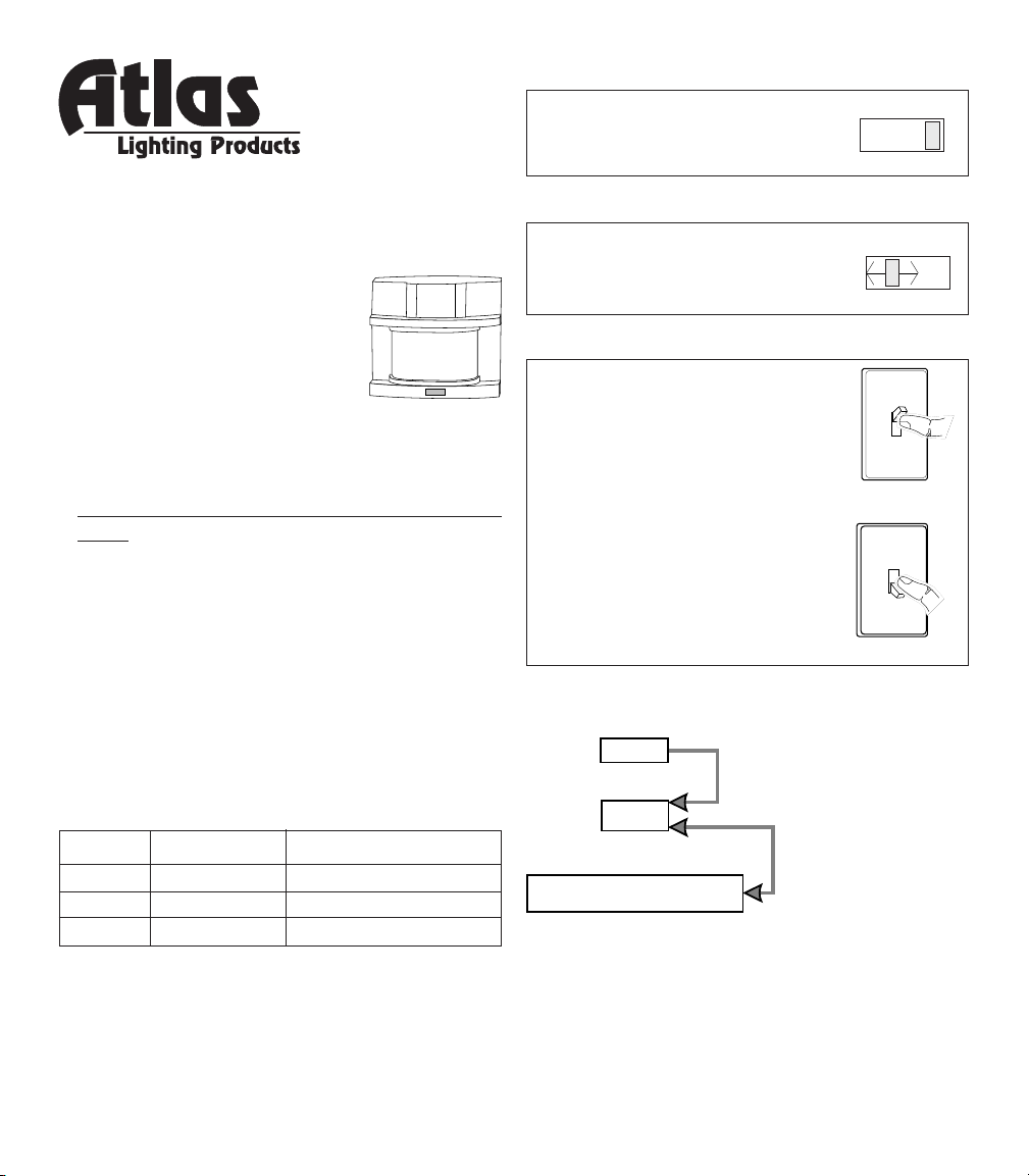
OPERATION
Mode: On-Time: Works: Day Night
Test 5 Sec x x
Auto 1, 5, 10 min. x
Manual Until Dawn* x
* resets to Auto Mode at dawn.
Note: When first turned on wait about 1 1/2 minutes
for the circuitry to calibrate.
TEST
Put the ON-TIME switch on the
bottom of the sensor in the TEST
position.
AUTO
Put the ON-TIME switch in the 1,
5, or 10 minute position.
MANUAL MODE
Manual mode only works at night
because daylight returns the sensor to AUTO.
Flip the light switch off for one
second then back on to toggle
between AUTO and MANUAL
MODE.
Manual mode works only with the
ON-TIME switch in the 1, 5, or 10
position.
ON-TIME
10 5 1 TEST
ON-TIME
10 5 1 TEST
1 Second OFF
then...
... back on.
Mode Switching Summary
TEST
AUTO
MANUAL MODE
* If you get confused while switching modes, turn
the power off for one minute, then back on. After
the calibration time the control will be in the
AUTO mode.
Move ON-TIME Switch to
1, 5, or 10 minutes
Flip light switch off
for one second
then back on*
240-029-A
© 2003 Atlas Lighting Products, Inc. 598-1096-01
Page 2
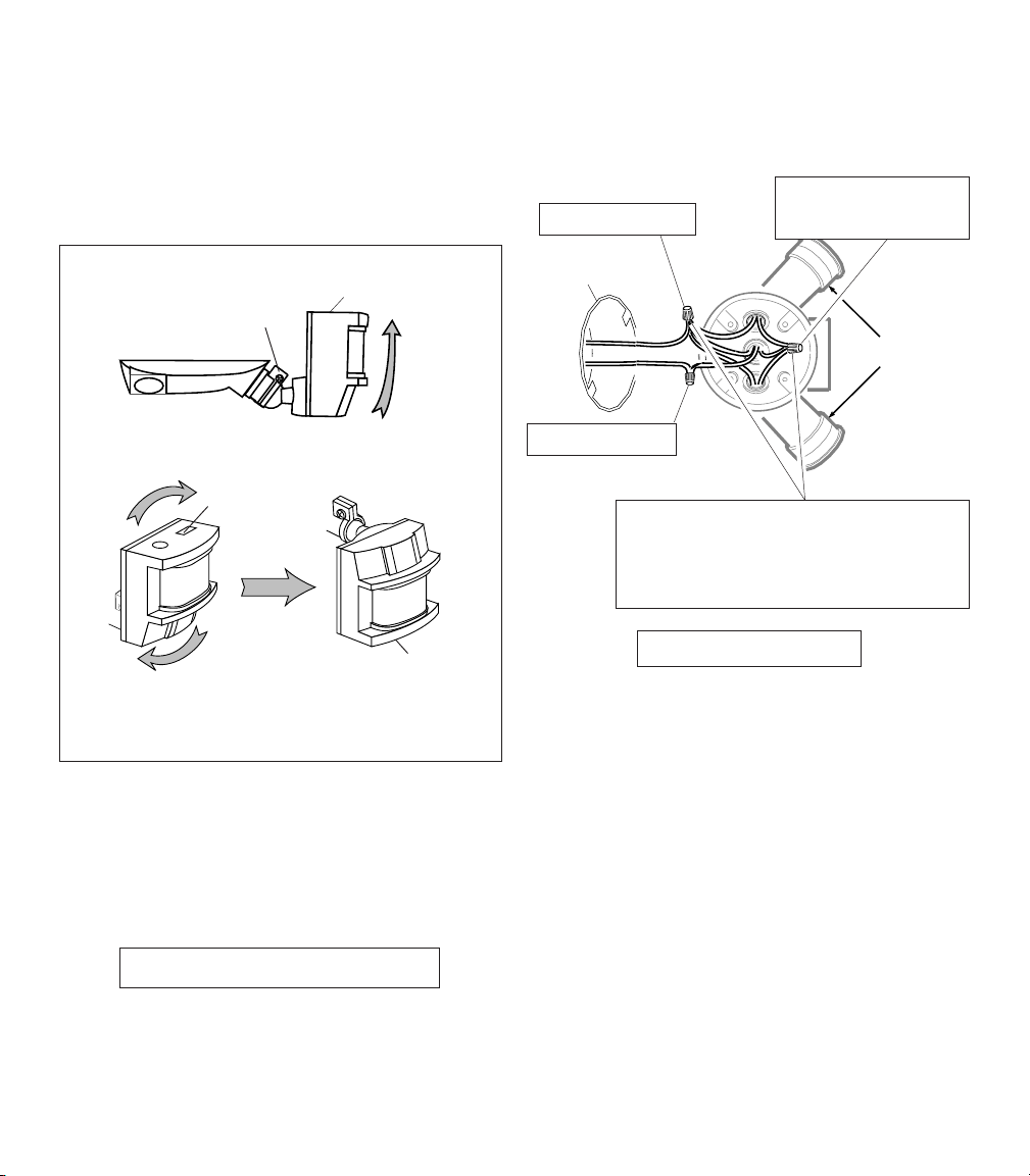
INSTALLATION
For under eave installation, the sensor head
must be rotated as shown in the next two steps for
proper operation and to avoid the risk of electrical
shock.
For eave mount only:
❒ Swing the sensor head towards the clamp
screw.
Clamp Screw
Controls
❒ After screwing the sensor into the wall plate,
connect the junction box wires to the Light
Control wires by twisting together and securing
with wire connectors.
Red Sensor Wire to
White to White
Junction
Box
Black Lamp Wire
Lamp Holders
❒ Rotate the sensor head clockwise 180° so the
controls face down.
Controls
Controls
If the sensor pops out of the ball joint, loosen the
clamp screw and push the sensor back into the
ball joint. Tighten the clamp screw when done.
These instructions show the sensor wired to floodlamps. The white sensor wire is neutral. The
black sensor wire is hot. The red wire is the
switched "hot" wire. The lighting load (Up to 500
Watts, 4.2A Maximum) is placed across the white
and red wires.
WIRE THE LIGHT CONTROL.
❒ Turn power off at the fuse or circuit breaker.
❒ Remove the existing light fixture, if present.
Black to Black
Optional: Connect additional load across
the white and red wires. Total lighting
load including lampheads on fixture must
not exceed 500 Watts (4.2A).
MOUNT THE LIGHT.
❒ Follow the instructions that came with your light
fixture for mounting and adjusting the light fixture.
❒ Keep regular PAR-38 lamps at least 1" (25 mm)
from the sensor. Halogen lamps should be kept
at least 2" (51 mm) from the sensor.
-2-
598-1096-01
Page 3

TEST AND ADJUSTMENT
❒ Turn on the circuit breaker and light switch.
NOTE: Sensor has a 1 1/2 minute calibration
period before it will detect motion. When
first turned on, wait 1 1/2 minutes.
❒ Turn the RANGE control to the mid position and
the ON-TIME control to the TEST position.
ON-TIME
10 5 1 TEST
Bottom of Sensor
Avoid aiming the control at:
• Objects that change temperature rapidly, such
as heating vents and air conditioners. These
heat sources could cause false triggering.
• Areas where pets or traffic may trigger the control.
• Nearby large, light-colored objects reflecting
light may trigger the shut-off feature. Do not point
other lights at the sensor.
RANGE
MIN MAX
❒ Loosen the clamp screw in
the sensor ball joint and
gently rotate the sensor.
❒ Walk through the cover-
age area noting where you
are when the lights turn on
Clamp
Screw
Ball
Joint
(also, the LED will flash
several times when motion
is detected). Move the sensor head up, down, or sideways to change the coverage area. Keep the sen-
Aim Sensor
Down for Short
Coverage
sor at least 1" (2.5 cm)
away from the lamps.
❒ Adjust the RANGE as
needed. RANGE set too
high may increase false
triggering.
❒ Secure the sensor head
Aim Sensor
Higher for Long
Coverage
by tightening the clamp screw. Do not over-
tighten the screw.
❒ Set the amount of TIME you want the lights to stay
on after motion is detected (1, 5, or 10 minutes).
Warning - Risk of fire. Do not aim the lamps at
a combustible surface within 3 ft. (1 m).
8 ft.
180°
(2.4m)
70 ft.
(21m)
Maximum Range Maximum
Coverage Angle
The sensor is less sensitive to motion directly
towards it, most sensitive to motion across its field
of view.
Motion
Motion
Sensor
Least Sensitive Most Sensitive
598-1096-01
SPECIFICATIONS
Range . . . . . . . . . . . . . . Up to 70 ft. (21 m) [varies with
surrounding temperature].
Sensing Angle . . . . . . . . Up to 180°
Electrical Load. . . . . . . . Up to 500 Watt (4.2A) Maxi-
mum Incandescent [Up to 250
Watt maximum each lamp
holder.]
Power Requirements. . . 120 VAC, 60 Hz
Operating Modes. . . . . . TEST, AUTO and MANUAL
MODE
Time Delay . . . . . . . . . . 1 , 5, 10 minutes
Range . . . . . . . . . . . . . . Adjustable
Atlas Lighting Products, Inc. reserves the right to discontinue products and to change specifications at any
time without incurring any obligation to incorporate new
features in products previously sold.
-3-
Page 4

TROUBLESHOOTING GUIDE
If you experience a problem with your Light Control, first follow this guide. For additional assistance write to:
Atlas Lighting Products, Inc. • Customer Service Department • P.O. Box 2348 • Burlington, NC 27216
SYMPTOM
Lights will not
come on.
Lights come on
in daylight.
Lights come on for
no apparent reason.
POSSIBLE CAUSE
1. Light switch is turned off.
2. Light is loose or burned out.
3. Fuse is blown or circuit breaker is turned
off.
4. Daylight turn-off is in effect
after dark)
5. Incorrect circuit wiring, if this is a new
installation.
6. Re-aim the sensor to cover desired area.
1. Light Control may be installed in a relatively dark location.
2. Light Control is in Test.
switch to an ON-TIME position)
1. Light Control may be sensing small
animals or automobile traffic
sensor)
2. Range is set too high.
.
.
(recheck
(Set control
.
(re-aim
(Reduce Range)
SYMPTOM
Lights stay on
continuously.
Lights flash on
and off.
.
Lights flash
once, then stay
off in Manual
Mode.
POSSIBLE CAUSE
1. A lamp is positioned too close to the sensor
or pointed at nearby objects that cause heat
to trigger the sensor.
away from the sensor or nearby objects)
2. Light Control is pointed toward a heat
source like an air vent, dryer vent, or
brightly-painted heat-reflective surface.
(Reposition sensor)
3. Light Control is in Manual Mode.
to Auto.)
1. Heat or light from the lamps may be turning the Light Control on and off.
tion the lamps away from the sensor)
2. Heat being reflected from other objects may
be affecting the sensor.
3. Light Control is in the Test mode and
warming up.
these conditions)
4. Light Control is detecting a light source.
(Reposition Light Control or lamp).
1. Sensor is detecting its own lights.
sition lamps to keep area below the sensor relatively dark.)
(Reposition the lamp
.
.
(Switch
(Reposi-
.
(Reposition sensor)
(Flashing is normal under
.
(Repo-
.
Atlas Lighting Products, Inc. warrants against defects in materials or workmanship for a period of five years from the date of
FIVE YEAR LIMITED WARRANTY
purchase for use, and agrees to repair or, at our option, replace a defective unit without charge for either parts or labor.
IMPORTANT: This warranty does not cover damage resulting from accident, misuse of abuse, lack of reasonable care, the
affixing of any attachment not provided with product, alteration of any attachments factory installed, loss of parts or subjecting
the fixture to any but the specified electrical service. This warranty does not cover failure of the bulb due to accidents, abuse,
misuse, vandalism, power surges, and acts of nature such as lightning damage. No responsibility is assumed for any special
incidental or consequential damages. Damages occurring during transit are not covered by this warranty-including UPS
shipments. To obtain warranty service, mail sales receipt as proof-of-purchase, date and a brief explanation of the nature of
the defect, to the address listed below. You will receive, by mail, a Return Goods Authorization number and full instructions
for returning defective merchandise. All returned goods must be accompanied by a Return Goods Authorization
number issued by Atlas Lighting Products, Inc.
NOTE: No other warranty, written or verbal, is authorized by Atlas Lighting Products, Inc. This warranty gives you specific
legal rights and you may also have other rights which vary from state to state. Some states do not allow the exclusion or
limitation of incidental or consequential damages or limitations on how long an implied warranty lasts, so the above exclusion
and limitations may not apply to you.
For information regarding replacement parts please write to:
Atlas Lighting Products, Inc.
Attn: Customer Service Department
P.O. Box 2348
Burlington, NC 27216
-4-
598-1096-01
 Loading...