

Page 1
GUARDIAN PRO
180 SeRieS
™
Requirements
• The light control requires 120-volts AC.
• If you want to use Manual Mode, the control must be
wired through a switch.
• So m e co d es r equ ire i nst all a ti o n by a
qualified electrician.
• This product is intended for use with the enclosed
gasket and with a junction box marked for use in wet
locations.
Models MLG180B
MLG180W
Meets the ENERGY STAR® guidelines
when used with 120 W Max bulbs.
Features
• Turns on lighting when motion is detected.
• Automatically turns lighting off.
• Photocell keeps the lighting off during daylight hours.
• LED indicates motion was sensed (day or night).
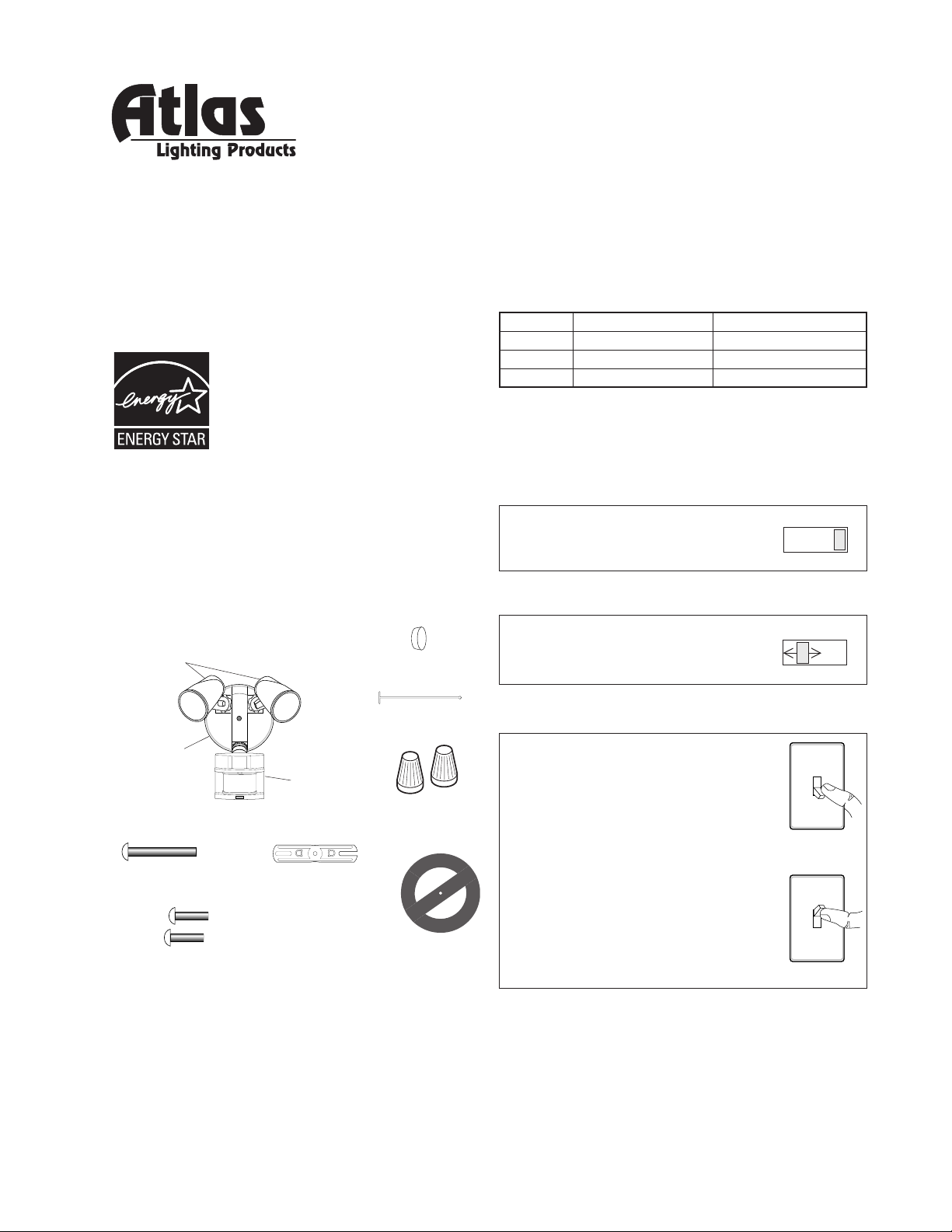
This package includes:
Bulb
Holders
Rubber Plug
Plastic Hanger
OPERATION
Mode: On-Time Works: Day Night
Test
Auto
Manual
Note: When first turned on wait about 1 1/2 minutes for
the circuitry to calibrate.
Put the ON-TIME switch on the bottom
of the sensor in the TEST position.
Put the ON-TIME switch in the 1, 5,
or 10 minute position.
5 Seconds x x
1, 5, or 10 Minutes x
To Dawn* x
* resets to Auto Mode at dawn.
TEST
ON-TIME
10 5 1 TEST
AUTO
ON-TIME
10 5 1 TEST
MANUAL MODE
Cover
Plate
Sensor
Light Control
Mounting Bolt
6 Screws
(3 sizes included)
© 2008 Atlas Lighting Products, Inc. 598-1092-02
Mounting Strap
2 Wire
Connectors
Gasket
Manual mode only works at night
because daylight returns the sensor to AUTO.
Flip the light switch off for one second then back on to toggle between
AUTO and MANUAL MODE.
Manual mode works only with the
ON-TIME switch in the 1, 5, or 10
position.
1 Second OFF
then...
... back on.
240-026-A
Page 2
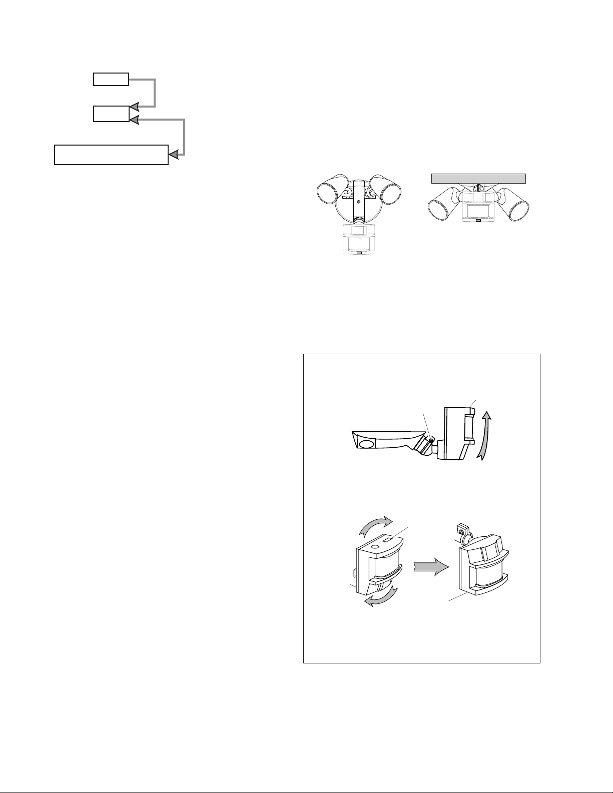
Mode Switching Summary
MANUAL MODE
AUTO
TEST
INSTALLATION
Move ON-TIME Switch to
1, 5, or 10 minutes
Flip light switch off
for one second then
back on*
* If you get confused while switching modes, turn the
power off for one minute, then back on. After the calibration time the control will be in the AUTO mode.
For easy installation, select an existing light with a wall
switch for replacement.
For best performance, mount the fixture about 8 ft. (2.4 m)
above the ground.
8 ft. (2.4 m), aiming the sensor down will reduce coverage
distance.
NOTE:
If fixture is mounted higher than
Wall Mount Eave Mount
For under eave installation, the sensor head must
be rotated as shown in the next two steps for proper
operation and to avoid the risk of electrical shock.
For eave mount only:
❒ Swing the sensor head towards the clamp screw
joint.
Controls
Clamp Screw
❒ Then rotate the sensor head clockwise 180° so the
controls face down.
Controls
Controls
If the sensor pops out of the ball joint, loosen the
clamp screw and push the sensor back into the ball
joint. Tighten the clamp screw when done.
2
598-1092-02
Page 3
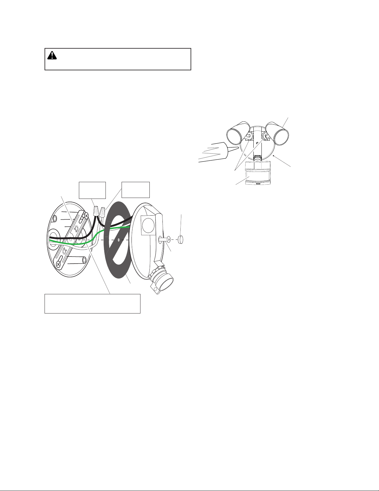
Wire the Light Control
WARNING: Turn power off at circuit breaker
or fuse.
❒ Remove the existing light fixture.
❒ Install the mounting strap as shown using two screws
that fit your junction box.
❒ The plastic hanger can be used to hold the fixture
while wiring. The small end of the plastic hanger
can be threaded through the hole in the center of
the cover plate. The small end then goes into one
of the slots on the mounting strap.
❒ Route the light control’s wires through the large
gasket holes.
❒ Twist the junction box wires and fixture wires together
as shown. Secure with wire connectors.
Mounting
Strap
Black to
Black
White to
White
Rubber
Plug
Mount the Light Control
❒ Align the light control cover plate and cover plate
gasket. Secure with the mounting bolt.
❒ Push the rubber plug firmly into place.
❒ If a wet location junction box was not used, caulk
the wall plate mounting surface with silicone
weather sealant.
To avoid water damage and electrical shock,
keep bulb holders 30° below horizontal.
Keep bulbs at least
1" (25 mm) from the
Lock Nut
❒ Adjust the bulb holders by loosening the lock nuts but
do not rotate the bulb holders more than 180° from
the factory setting. When screwing in the floodlamps,
do not overtighten.
sensor. Do not allow
the bulbs to block
the lens.Lens
Gasket
Junction box ground wire to
green ground screw on fixture.
Mounting
Bolt
598-1092-02
3
Page 4

TEST AND ADJUSTMENT
❒ Turn on the circuit breaker and light switch.
NOTE: Sensor has a 1 1/2 minute warm up period
before it will detect motion. When first turned
on, wait 1 1/2 minutes.
NOTE: Meets the ENERGY STAR® guidelines when
used with 120 W Max bulbs.
NOTE:
the sensor down will reduce coverage distance.
The detector is less sensitive to motion directly towards it.
If fixture is mounted higher than 8 ft. (2.4 m), aiming
Motion
Motion
❒ Turn the RANGE control to the medium position
(halfway between MIN and MAX) and the ON-TIME
control to the TEST position.
ON-TIME
10 5 1 TEST
RANGE
MIN MAX
Bottom of Sensor
Avoid aiming the control at:
• Objects that change temperature rapidly, such as
heating vents and air conditioners. These heat
sources could cause false triggering.
• Areas where pets or traffic may trigger the control.
• Nearby large, light-colored objects reflecting light
may trigger the shut-off feature. Do not point other
lights at the sensor.
Sensor
Least Sensitive Most Sensitive
❒ Loosen the clamp screw in the
sensor ball joint and gently
rotate the sensor.
❒ Walk through the coverage
area noting where you are
when the lights turn on (also,
the LED will flash several times
when motion is detected). Move
the sensor head up, down, or
sideways to change the coverage area. Keep the sensor at
least 1" (25 mm) away from
the bulbs.
❒ Adjust the RANGE as needed.
RANGE set too high may
increase false triggering.
❒ Secure the sensor head by
tightening the clamp screw.
Do not overtighten the screw.
❒ Set the amount of TIME you want the lights to stay
on after motion is detected (1, 5, or 10 minutes).
Aim Sensor
Down for Short
Coverage
Aim Sensor
Higher for Long
Coverage
Clamp
Screw
Ball
Joint
8 ft.
(2.4 m)
70 ft.
(21 m)
180°
Maximum Range Maximum
Coverage Angle
WARNING: Risk of fire. Do not aim the bulbs
at a combustible surface within 3 ft. (1 m).
4
598-1092-02
Page 5

SPECIFICATIONS
Range . . . . . . . . . . . . Up to 70 ft. (21 m) [varies with
surrounding temperature].
Sensing Angle . . . . . . Up to 180°
Electrical Load . . . . . . Up to 300 Watt Maximum In-
candescent [Up to 150 Watt
maximum each bulb holder.]
Operating Modes . . . . TEST, AUTO and MANUAL
MODE
Time Delay . . . . . . . . 1, 5, 10 minutes
Atlas Lighting Products, Inc. reserves the right to discontinue products and to change specifications at any
time without incurring any obligation to incorporate
new features in products previously sold.
Power Requirements . 120 VAC, 60 Hz
Replacement Lamp . . Up to 150 Watt Maximum PAR38
Incandescent or Halogen (Not
CFL) Bulbs.
TROUBLESHOOTING GUIDE
If you experience a problem with your Light Control, first follow this guide. For additional assistance write to:
Atlas Lighting Products, Inc. • Customer Service Department • P.O. Box 2348 • Burlington, NC 27216
SYMPTOM POSSIBLE CAUSE SOLUTION
Lights will not come
on.
Lights come on in daylight.
Lights come on for no
apparent reason.
Lights turn off too late in
Dusk-to-Dawn setting.
Lights stay on continuously.
Lights flash on and off. 1. Heat or light from the flood lamps may be turning the
Lights flash once, then
sta y off i n manual
mode.
1. Light switch is turned off.
2. Flood lamp is loose or burned out.
3. Fuse is blown or circuit breaker is turned off.
4. Daylight turn-off is in effect.
5. Incorrect circuit wiring, if this is a new installation.
6. Light control aimed in wrong direction.
1. Light control may be installed in a relatively dark
location.
2. Light control is in TEST.
1. Light control may be sensing small animals or auto
mobile traffic.
2. Range is set too high.
Light control may be installed in a relatively dark location.
1. A flood lamp is positioned too close to the light control
or pointed at nearby objects that cause heat to trigger
the light control.
2. The light control may be picking up a heat source
like an air vent, dryer vent, or brightly painted, heatreflective surface.
3. Light control is in manual mode.
light control on and off.
2. Heat being reflected from other objects may be turning the light control on and off.
3. Light control is in the TEST mode and warming up.
4. Light may be leaking through the flood lamp reflectors.
Light control is detecting its own lights. Reposition flood lamps to keep area below the light
1. Turn light switch on.
2. Check flood lamp and replace if burned out.
3. Replace fuse or turn circuit breaker on.
4. Recheck after dark.
5. Verify wiring is correct.
6. Re-aim light control to cover desired area.
1. The fixture is operating normally under these conditions.
2. Set control switch to 1, 5, or 10 minutes.
-
1. Re-aim light control.
2. Reduce range.
Relocate light control.
1. Reposition the flood lamp away from the light control
or nearby objects.
2. Reduce range.
3. Switch light control to AUTO.
1. Reposition the flood lamp away from the light control.
2. Reposition light control.
3. Flashing is normal under these conditions.
4. Replace the flood lamps with new high quality PAR
38 lamps. (Make sure the metal lamp protectors are
installed).
control relatively dark.
598-1092-02
5
Page 6

FIVE YEAR LIMITED WARRANTY
Atlas Lighting Products, Inc. warrants against defects in materials or workmanship for a period of five years
from the date of purchase for use, and agrees to repair or, at our option, replace a defective unit without
charge for either parts or labor. IMPORTANT: This warranty does not cover damage resulting from accident,
misuse of abuse, lack of reasonable care, the affixing of any attachment not provided with product, alteration
of any attachments factory installed, loss of parts or subjecting the fixture to any but the specified electrical
service. This warranty does not cover failure of the bulb due to accidents, abuse, misuse, vandalism, power
surges, and acts of nature such as lightning damage. No responsibility is assumed for any special incidental
or consequential damages. Damages occurring during transit are not covered by this warranty-including UPS
shipments. To obtain warranty service, mail sales receipt as proof-of-purchase, date and a brief explanation of
the nature of the defect, to the address listed below. You will receive, by mail, a Return Goods Authorization
number and full instructions for returning defective merchandise. All returned goods must be accompanied
by a Return Goods Authorization number issued by Atlas Lighting Products, Inc.
NOTE: No other warranty, written or verbal, is authorized by Atlas Lighting Products, Inc. This warranty gives
you specific legal rights and you may also have other rights which vary from state to state. Some states do
not allow the exclusion or limitation of incidental or consequential damages or limitations on how long an
implied warranty lasts, so the above exclusion and limitations may not apply to you.
For information regarding replacement parts please write to:
Atlas Lighting Products, Inc.
Attn: Customer Service Department
P.O. Box 2348
Burlington, NC 27216
6
598-1092-02
Page 7

Notes / Notas _________________
_____________________________
_____________________________
_____________________________
_____________________________
_____________________________
_____________________________
_____________________________
_____________________________
_____________________________
_____________________________
_____________________________
_____________________________
_____________________________
_____________________________
_____________________________
_____________________________
_____________________________
_____________________________
598-1092-02
7
Page 8

Notes / Notas _________________
_____________________________
_____________________________
_____________________________
_____________________________
_____________________________
_____________________________
_____________________________
_____________________________
_____________________________
_____________________________
_____________________________
_____________________________
_____________________________
_____________________________
_____________________________
_____________________________
_____________________________
_____________________________
8
598-1092-02
 Loading...