

Page 1

KDX-500 INSTALLATION
______________________________________________________________________________
Site Requirements
The selection of a suitable location is essential when installing the key service unit (KSU). The
area should be clean, dry, static-free, temperature controlled, and accessible only to authorized
personnel. When selecting a site, give careful consideration to the following:
♦ Ample space must be allowed to mount the cabinet(s) and MDF (Main Distribution Frame)
and to allow for removal of the KSU covers to access assemblies and cards within the
cabinet(s).
♦ A well-ventilated and well-lighted area having with a temperature range of 32-100° F (0-40°
C) and 10%-90% relative, noncondensing humidity. The area must not be exposed to direct
sunlight, heat or dust. Optimal temperature range is 40-70° F.
♦ A dedicated 110/220 Volt AC, 15 Amp, 50/60 Hz, single phase, 3 wire, parallel blade with
ground power outlet should be located within 6 feet of the KSU. Additional outlets for music
source, paging amplifier, etc. as needed. The AC receptacles must be third-wire grounding
type. The third-wire ground must be connected to an approved earth ground through the
single-point grounding circuit at the power distribution panel.
♦ Avoid areas that produce radio frequency interference (RFI) or electro-magnetic interference
(EMI). (eg. electric welding equipment, radio frequency transmitters, magnets, refrigerators,
copy machines, microwave ovens, etc.)
♦ Locate the KSU and stations so as to minimize cable length. All station cables must be 2-pair
twisted-pair cable and must be home run. The Digital Keyphone may be wired differently.
Cabling lengths must not exceed the following:
Analog Keyphones: Diameter
26 gauge 460 feet
24 gauge 750 feet
22 gauge 1150 feet
Single-Line Telephones: 800 ohms using 22 gauge – 5000 feet
Digital Keyphone 24 gauge 600-3000 feet depending upon wiring configuration.
(See Fig. 22)
______________________________________________________________________________
June 2002 installation Page 1
Distance
Page 2

KDX-500 INSTALLATION
______________________________________________________________________________
♦ The CO/PBX line terminations should be within 5 feet of the cabinet/main distribution frame.
♦ Make sure there is a good earth ground utilizing #12 AWG or larger standard, copper wire
within 25 feet of the KSU. A metallic COLD water pipe usually provides a reliable ground
path. Carefully check that the pipe does not contain insulated joints that could isolate the
ground. (The pipe must be metallic from the point of ground to the connection to the water
main outside the building).
♦ Recommended: use a surge/spike protector.
AC: Innovative Technology Equalizer II or equivalent.
CO: Innovative Technology MDF 6/12/24 or equivalent.
KDX-500
The KDX-500 system consists of up to 4 cabinets. One Main KSU cabinet (with 3 slots for the
3 common control cards and 5 slots for peripheral cards) and up to 3 Expansion KSU cabinets
(each with 8 slots for peripheral cards).
The current peripheral cards are:
♦ COU-A Analog loop start trunks (8 circuits)
♦ STU-A Analog Keyphone stations (8 circuits)
♦ DSU-16 Digital Keyphone stations (16 circuits)
♦ SLU-16 Analog Single Line telephones (16 circuits)
Future peripheral cards are:
♦ T-1 / PRI Trunk card
♦ BRI card
♦ DID / Caller ID Card
______________________________________________________________________________
Page 2 Installation June 2002
Page 3
KDX-500 INSTALLATION
______________________________________________________________________________
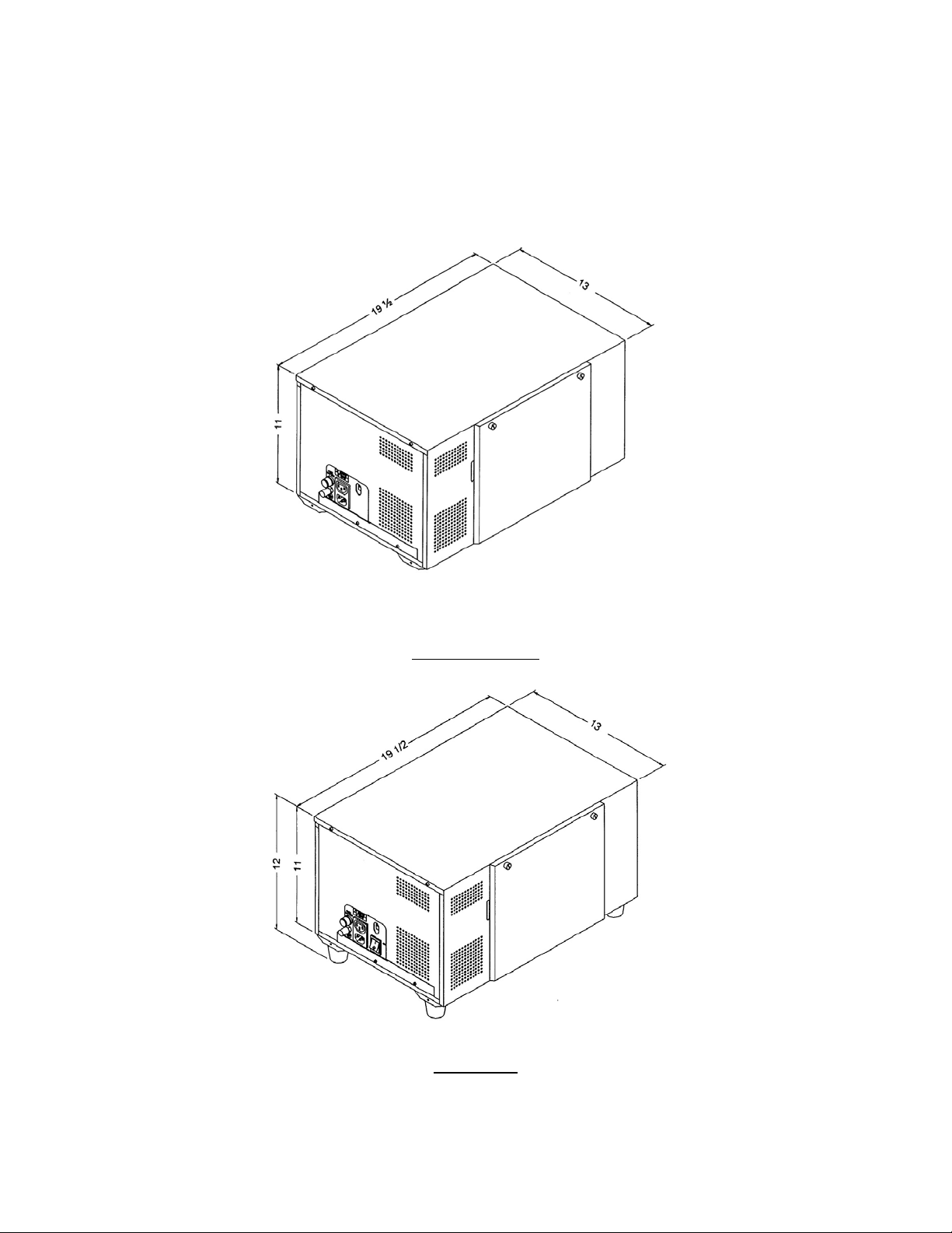
Expansion KSU
Main KSU
______________________________________________________________________________
June 2002 installation Page 3
Page 4
KDX-500 INSTALLATION
______________________________________________________________________________
INSTALLATION
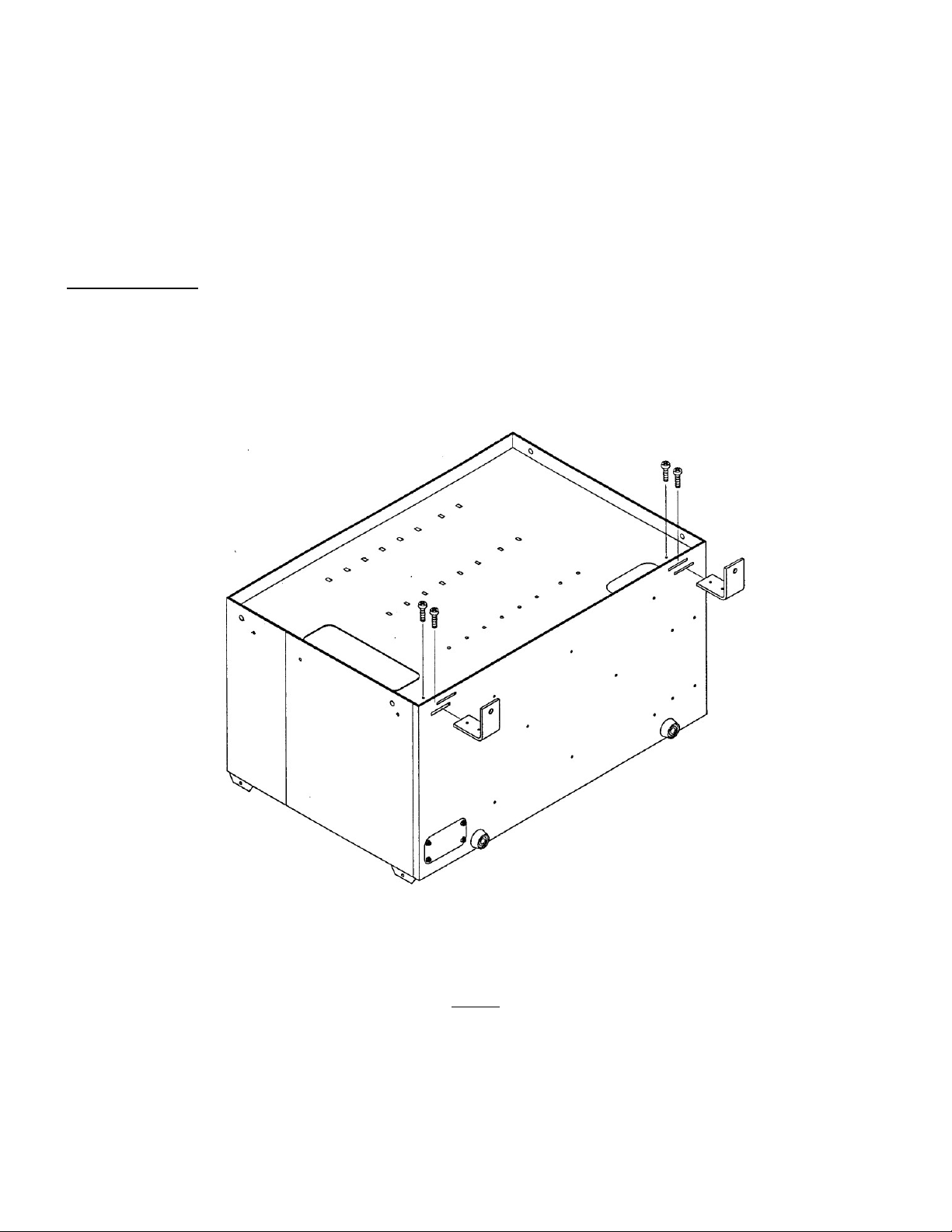
The KXD-500 KSU can be installed “free-standing” or wall mounted. For wall mounting remove
the two screws on the front of the cabinet securing the top. Lift up the top panel from the front
and remove it. Remove the two “L” brackets (each secured by two screws) and reinstall them
as shown in Fig. 1.
Fig. 1
When wall mounting, a ¾” thick plywood backboard should be attached to the equipment room
wall for mounting the cabinet(s) and associated equipment. The backboard should be large
______________________________________________________________________________
Page 4 Installation June 2002
Page 5

KDX-500 INSTALLATION
______________________________________________________________________________
enough to allow sufficient space for the MDF connecting blocks and optional equipment to be
mounted and serviced conveniently.
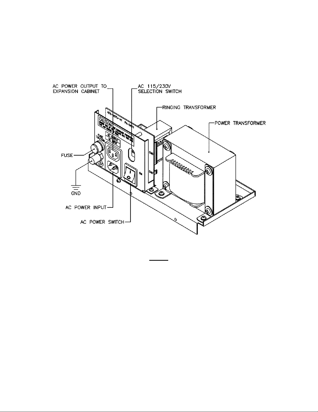
POWER TRANSFORMER ASSEMBLY
Once the cabinet is in place, install the KDX-ACPU-A1 Power Transformer Assembly (see Fig. 2)
into the main KSU. The cables from this assembly plug into the PSU-A Unit. (See Fig. 3)
• Remove cover plate on left side of KSU
• Place power assembly in cabinet. Secure with two screws provided
• Connect CN7 on Power Assembly to CN6 on PSU-A Unit (2 blue wires)
• Connect 2 yellow wires from large power transformer to CN3 on PSU-A Unit
______________________________________________________________________________
June 2002 installation Page 5
Page 6
KDX-500 INSTALLATION
______________________________________________________________________________
• Connect 8-wire connector from Ringing Transformer to CN4 on PSU-A Unit
Fig. 2
______________________________________________________________________________
Page 6 Installation June 2002
Page 7
KDX-500 INSTALLATION
______________________________________________________________________________
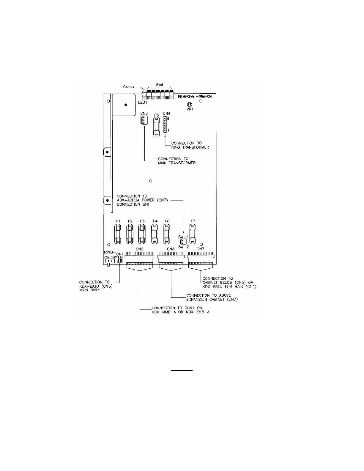
Fig. 3
______________________________________________________________________________
June 2002 installation Page 7
Page 8
KDX-500 INSTALLATION
______________________________________________________________________________
FUSES (PSU-A UNIT) (See Fig. 3)
LED INDICATION FUSE
n
n
n
n
n
n
n
Steady Green
Steady Red F2 3A 250V
Steady Red F3 1A 250V
Steady Red F1 3A 250V
Steady Red F6 6A 250V
Steady Red F4 .5A 250V
Very Fast Flashing Red F5 .5A 250V
Note: 1) An unlit LED indicates a blown fuse. Be sure to replace the fuse with the same type
and rating.
2) Fuse F7 (6A / 250V) is for the built in trickle charger for external batteries that may be
attached to the BATU Unit. There is no LED Monitoring this fuse.
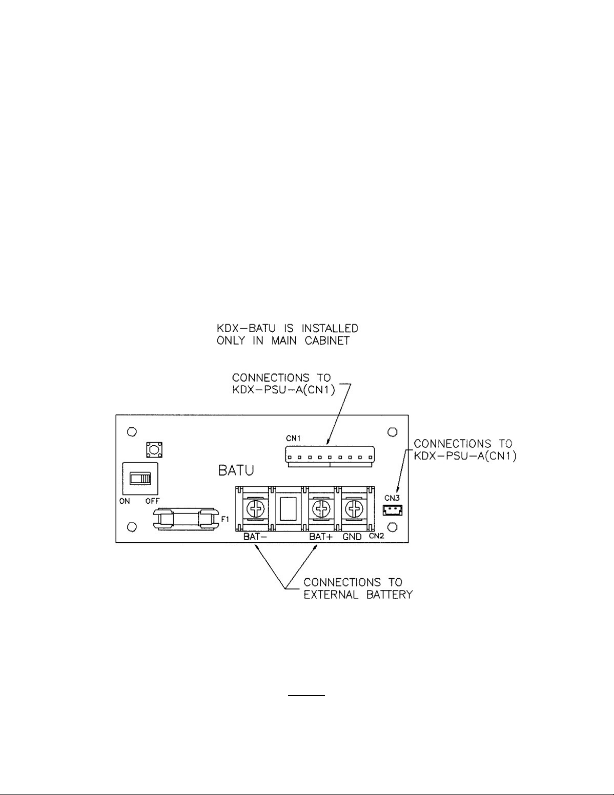
BATU UNIT
The BATU Unit provides the capability to connect external batteries to the system to provide
for complete system operation in the event of local power failure. Attach batteries
( 24VDC ) to the BATU Unit at the appropriate terminals. (See Fig. 4) The system applies a
trickle charge to the battery when it is not in use.
Keep the battery(s) dry and clean. Avoid damp wet areas or areas where the battery may
be easily damaged. Wires should run from the battery(s) to the terminals on the BATU
Unit. When connecting to the BATU, pay particular attention to matching the positive and
negative connections. Improper connection will damage the power supply. When operating
from the battery, the system will automatically cut off the power supply from the battery
when the voltage gets too low, so that the battery can be recharged.
CAUTION!!!! To reduce the risk of fire or injury please note the following:
Do not dispose of the battery(s) in a fire. The cell may explode. Check with local
codes for special disposal instructions.
Do not open or mutilate the battery(s). Released electrolyte is corrosive and may
cause damage to the eyes or skin. It may be toxic if swallowed.
______________________________________________________________________________
Page 8 Installation June 2002
Page 9
KDX-500 INSTALLATION
______________________________________________________________________________
Exercise care in handling the battery(s) in order not to short the battery with
conducting materials such as rings, bracelets and keys. The battery may overheat
and cause burns.
Observe proper polarity orientation between the battery(s) and BATU Unit.
Do not mix battery(s) of different sizes or from different manufacturers in this product.
The length of time system operation is maintained under battery power depends on battery
capacity. Typical system support for the 24 Volt battery(s) is approximately one hour.
Fig. 4
______________________________________________________________________________
June 2002 installation Page 9
Page 10
KDX-500 INSTALLATION
______________________________________________________________________________
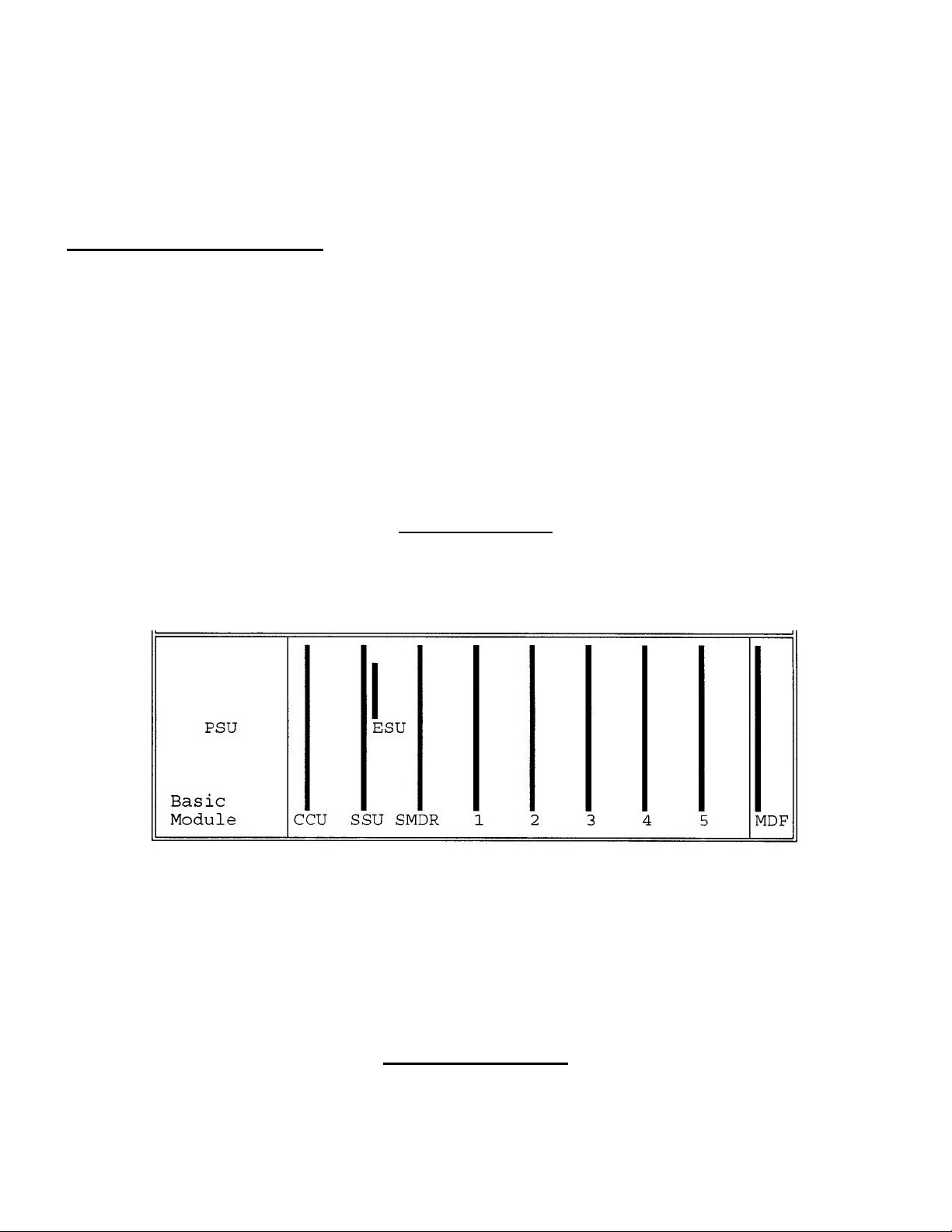
COMMON CONTROL CARDS
See Fig. 5 for card locations. Slots labeled FPU are for Peripheral Cards (Stations /
Trunks). The 3 Common Control Cards are 1) CCU-A Card (Central Processor), 2) SSU-A
Card (System Services Card) and 3) SMDRU Card (SMDR and Serial Ports).
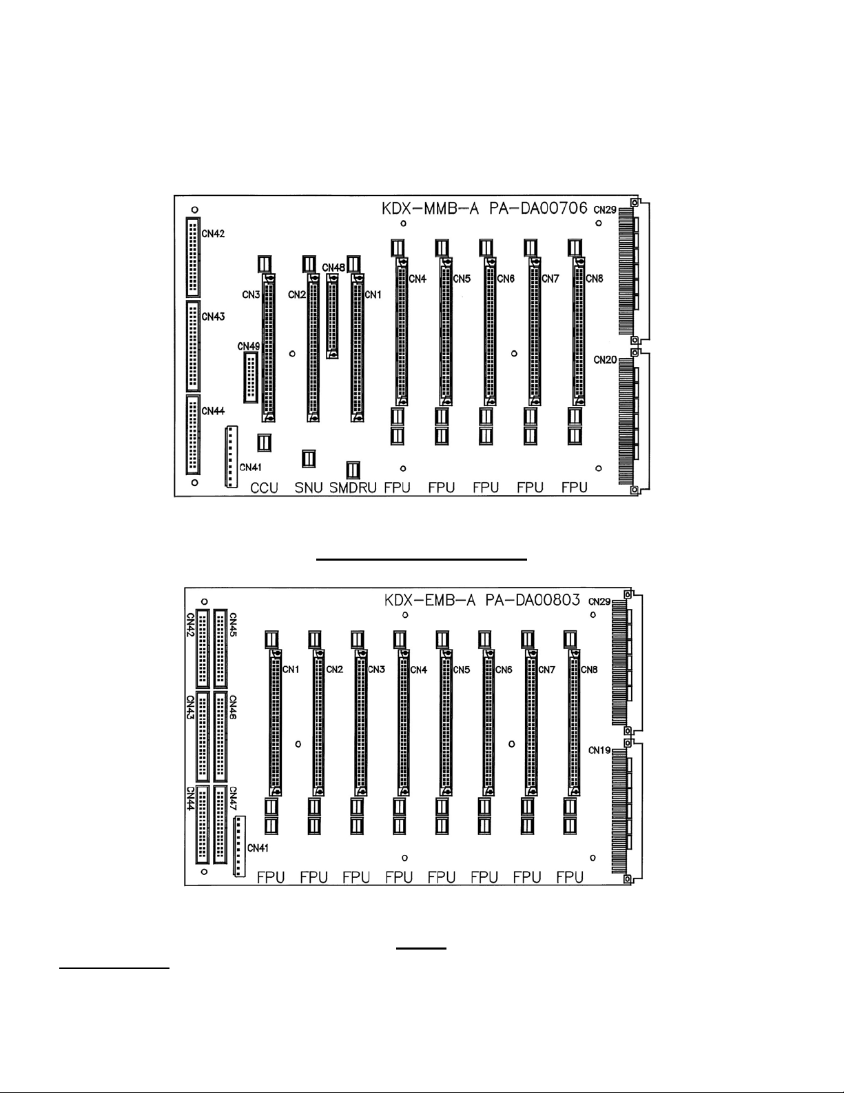
Main KSU Layout
Main KSU Backplane
______________________________________________________________________________
Page 10 Installation June 2002
Page 11
KDX-500 INSTALLATION
______________________________________________________________________________
Expansion KSU Backplane
CCU-A CARD (CENTRAL PROCESSOR)
Fig. 5
______________________________________________________________________________
June 2002 installation Page 11
Page 12

KDX-500 INSTALLATION
______________________________________________________________________________
The CCU Card is the main controller for the system. There are 4 LED’s on the card:
LED 1 (Very Fast Flashing Green)
LED 2/3 (Alternating Slow Flashing Red)
LED 4 (Red)
Controlled by Switch 1 (Battery). Turning switch ON activates the
battery (LED 4 lit steady)
Fig. 6
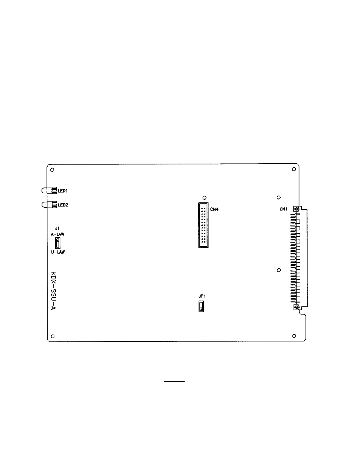
SNU-A CARD (SYSTEM SERVICES CARD)
______________________________________________________________________________
Page 12 Installation June 2002
Page 13
KDX-500 INSTALLATION
______________________________________________________________________________
The SNU Card provides the common service features for the system. There are 2 LED’s on
the card:
LED 1 (Slow Flashing Red)
LED 2 (Steady Red)
Jumper J1 should be set to the U-LAW position. A-LAW setting is for Europe
Fig. 7
______________________________________________________________________________
June 2002 installation Page 13
Page 14
KDX-500 INSTALLATION
______________________________________________________________________________
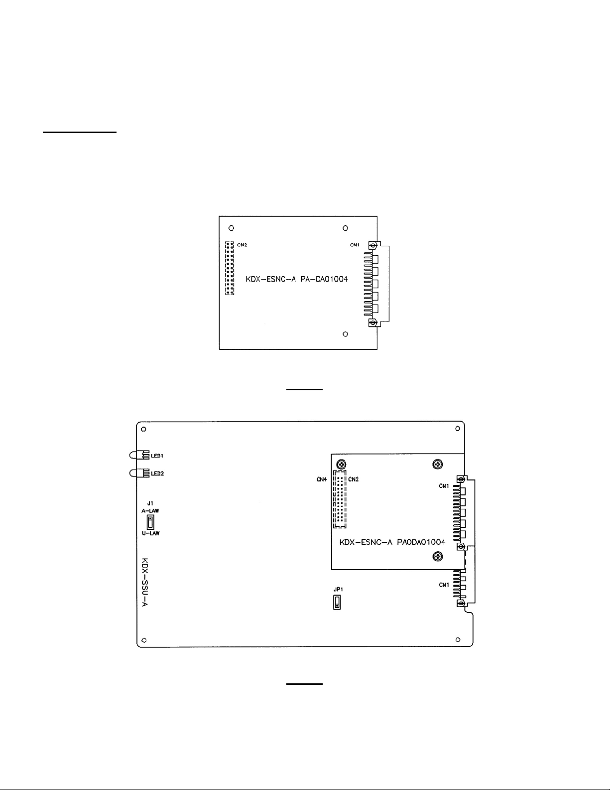
ESNC CARD (EXPANSION SWITCHING NETWORK CARD)
The ESNC Card is required when the 2
nd
and 3rd expansion cabinets are used. It adds the
additional 256 X 256 switching channel array required for these cabinets. The ESNC Card
is plugged into CN4 on the SSU Card and secured with the screws provided.
Fig. 8
Fig. 9
______________________________________________________________________________
Page 14 Installation June 2002
Page 15

KDX-500 INSTALLATION
______________________________________________________________________________
SMDR CARD
The SMDR Card provides for 1 Parallel Port connection (CN7) on the MDF-F1 (see Fig. 14).
This provides interface for a standard parallel printer (SMDR). This card also provides for 4
RS-232 connections to specific external devices. These connections are made through 4
DB-9 connectors on the MDF-F1 card located on the right side of the main KSU. The 4
ports are assigned as follows:
Port 1 (CN8) is for PC Programming (Future Feature)
Port 2 (CN9) is for Call Records & Reporting (SMDR)
Port 3 (CN10) is for Voice Mail Interface (SMDI)
Port 4 (CN11) is for InnFone Integration
There are 6 LED’s on the SMDR Card:
LED 1 (Fast Flashing Green)
LED 2-5 (Red) These flash whenever data is transmitted through CN8 - CN11
LED 6 (Red) Controlled by Switch 1 (Battery). Turning switch ON activates the
battery (LED 6 lit steady)
______________________________________________________________________________
June 2002 installation Page 15
Page 16

KDX-500 INSTALLATION
______________________________________________________________________________
Dipswitch (DSW1)
Switch
1 Not Used (Normally OFF)
2 Not Used (Normally OFF)
3 ON (Parallel / CN7) OFF (Serial / CN9) SMDR Output
4 Not Used (Normally OFF)
5 Not Used (Normally OFF)
6 Not Used (Normally OFF)
7 Not Used (Normally OFF)
8 ON only for use with ATLAS InnPhone
Fig. 10
______________________________________________________________________________
Page 16 Installation June 2002
Page 17

KDX-500 INSTALLATION
______________________________________________________________________________
INTERFACE CARDS
All Interface Card Slots (FPU) in the KSU are universal. Any type of interface card can be
installed in any Interface Card Slot. It is recommended that all station cards be installed
first. Install trunk cards after station cards have been installed to allow for easier expansion
in the future.
SLU-16
Single Line Telephone Card (16 Ports)
Each port requires a 1-pair connection. The SLU-16 provides 16 ports for single line
telephone connections. There is an LED (Red) for each port to indicate the status of that
port. ON means the port is in use. (the station is off-hook) Connection is made through the
amphenol connector on the MDF located on the right side of the main and expansion
KSU(s).
STU-A Analog Keyphone Card (8 Ports)
Each port requires a 2-pair connection. The STU-A provides for connection of 8 analog
keyphone sets. There is an LED (Red) for each port to indicate the status of that port. ON
means the port is in use. (the station is off-hook) Connection is made through the amphenol
connector on the MDF located on the right side of the main and expansion KSU(s).
DSU-16 Digital Station Card (8 Ports)
Each port requires a 2-pair connection. The DSU-16 provides for connection of up to 16
Digital Keyphone sets, digital DSS units, or an analog terminal interface (ATI). There is an
LED (Red) for each port to indicate the status of that port. ON means the port is in use.
Connection is made through the amphenol connector on the MDF located on the right side
of the main and expansion KSU(s).
COU-A
Analog Trunk Card (8 Circuits)
Each trunk requires a 1-pair connection. The COU-A provides for connection of 8 loop start
interface circuits. There is an LED (Red) for each port to indicate the status of that port. ON
means the port is in use. Connection is made through RJ-14 Modular jacks mounted on the
front edge of each COU-A card. (See Fig. 11)
FUTURE INTERFACE DEVICES
T-1 Trunk / PRI Card
BRI Card
DID / Caller ID Card
______________________________________________________________________________
June 2002 installation Page 17
Page 18

KDX-500 INSTALLATION
______________________________________________________________________________
CARD INSTALLATION
COMMON CONTROL CARDS
The CCU (Central Processor), SNU (System Services) and SMDR Cards MUST ONLY BE
INSERTED OR REMOVED when power to the Main KSU is OFF! These cards are installed
in the appropriate slots (CCU / SNU / SMDR) in the Main KSU (see Fig. 5)
PERIPHERAL CARDS
The Peripheral Cards (Trunks / Stations) may be removed and reinstalled at any time with
power ON. An example of this would be for troubleshooting or replacing a known defective
card. Peripheral cards are installed in the balance of the slots (Labeled FPU) in the Main
KSU and all slots of all Expansion KSUs.
When expanding the system (adding additional trunk or station cards) the system needs to
be powered down, the card inserted and the system powered up again.
Before powering down, verify (on the CCU Card) that the battery switch (SW1) is ON,
LED 4 is lit (indicating that SW1 is ON) and dipswitch 1 (in DSW1) is ON.
Failure to do this will result in loosing previously programmed information.
CABLE CONNECTIONS
COU-A (TRUNK) CARD CABLE CONNECTIONS
Connections (Central Office / PBX) to the COU Card are made directly at the card through
the 4 RJ14 connectors mounted on the front edge of each card. (See Fig. 11) Using a
standard 4 conductor modular cord the trunks are connected as follows:
______________________________________________________________________________
Page 18 Installation June 2002
Page 19

KDX-500 INSTALLATION
______________________________________________________________________________
RJ14 Trunks
PH1 1 Inner Pair (Green / Red)
2 Outer Pair (Black / Yellow)
PH2 3
4
PH3 5
6
PH4 7
8
Fig. 11
______________________________________________________________________________
June 2002 installation Page 19
Page 20

KDX-500 INSTALLATION
______________________________________________________________________________
The system allows for a maximum of 12 COU Cards. All FPU slots are universal, however for
most efficient use of cabling, COU Cards should be installed after station cards in each cabinet.
(See Fig. 12)
Fig. 12
STATION CARD CABLE CONNECTIONS
All station card connections are made through the MDF Units located on the right side of the
Main and Expansion KSUs. The MDF in the Main KSU (MDF-F1) has 4 amphenol
connectors labeled CN1 – CN4. (See Fig. 14)
The MDF in each expansion KSU (MDF-F2) has 6 amphenol connectors labeled CN1 –
CN6. (See Fig. 19)
______________________________________________________________________________
Page 20 Installation June 2002
Page 21

KDX-500 INSTALLATION
______________________________________________________________________________
Each FPU Card slot provides for 16 ports (1 pair each). Each amphenol connector on the MDF
brings out 24 pair – which is 1 ½ card slots –or, all ports on one card slot and the first half of the
ports on the next card slot. See Appendix A which is a complete form showing all card slots and
the appropriate amphenol connector assigned to it. This form provides a convenient way to keep a
record of all cards installed in your system. The following example shows a system with three
station cards and how they are assigned in the amphenol connectors (3 card slots = 2 amphenol
connectors). Default 3-digit numbering is used.
Fig. 13
______________________________________________________________________________
June 2002 installation Page 21
Page 22

KDX-500 INSTALLATION
______________________________________________________________________________
The STU-A Card provides for 8 Analog Keyphones. Port one is connected to the
White/Blue pair and White/Orange pair (2 pair connection).
The DSU-16 card provides for 16 Digital Keyphones on 8 ports. Each of the 8 positions on
this card can have 2 Digital Keyphones attached to it. The phones are connected in
parallel. Remove the desk/wall mount adapter from the base of the Digital Keyphone. This
will reveal 4 dipswitches. The phone with the switches set: 1,2 OFF / 3,4 ON will be port
17 and the phone with the switches set: 1,2 ON / 3,4 OFF will be port 18. Both port 17 and
18 are connected to the white/blue and white/orange pair (2 pair connection). The phones
are wired in parallel but there are some limitations that must be observed. (See Fig. 22)
Examples:
1) A single Digital Keyphone can be connected to a cable run up to 3000’ in length.
2) A cable run of up to 1500’ can be terminated in two parallel runs (2 pair) up to a
maximum of 50’. One phone uses the B1 channel (1,2 OFF / 3,4 ON). The other phone
uses the B2 channel (1,2 ON / 3,4 OFF).
3) 2 parallel cables (2 pair) can be run a maximum of 600’ from the MDF but the difference
in length between the two cables cannot exceed 50’.
The SLU-16 card provides for 16 single line devices. The first SLT on this card is port 25. It
is connected to the red/brown pair (1 pair connection).
MDF-F1
The MDF in the Main KSU provides for many connections to external devices as well as for
the station cards in this cabinet (See Fig. 14)
CN1-CN4 25 pair amphenol cable connections for stations
CN7 DB25 connector for standard parallel printer cable for SMDR Printer.
CN8 DB9 connector for PC Programming.
CN9 DB9 connector for call records and reporting
CN10 DB9 connector for Voice Mail Interface (SMDI)
CN11 DB9 connector for caller ID, InnFone, ACD Interface or PMS Interface.
CN12 3 pairs of screw terminals for connections of external page output, external
music source #1 and external music source #2.
______________________________________________________________________________
Page 22 Installation June 2002
Page 23

KDX-500 INSTALLATION
______________________________________________________________________________
CN13 6 pairs of screw terminals for connection to devices which can be controlled
by relays.
The Main and Expansion KSU MDFs are all equipped with 25 pair female type amphenol
connectors. The installer should run 25 pair cables with male amphenol connectors from his
own MDF (eg: 66 type block).
The 25-pair cables can exit the KSU from the bottom right hand side or from the back of the
KSU.
Fig. 14
______________________________________________________________________________
June 2002 installation Page 23
Page 24

KDX-500 INSTALLATION
______________________________________________________________________________
EXPANSION KSU(s)
Expansion KSU(s) are mounted on top of the Main KSU. First remove the top panel of the
Main KSU. Then place the expansion KSU on top of the Main KSU. (See Fig. 15) The
original top of the Main KSU is then installed as the top of the Expansion KSU.
Fig. 15
______________________________________________________________________________
Page 24 Installation June 2002
Page 25

KDX-500 INSTALLATION
______________________________________________________________________________
Connect the flat ribbon cables between the backplanes of the two KSUs as shown in Fig.
16. Connect the multi-conductor cable between CN5 of the Main KSU and CN7 of the
Expansion KSU. CN5 and CN7 are located on the PSU-A Power Boards as shown in Fig.
17.
Fig. 16
______________________________________________________________________________
June 2002 installation Page 25
Page 26

KDX-500 INSTALLATION
______________________________________________________________________________
Expansion KSU #2
Expansion KSU #1
Main KSU
Fig. 17
______________________________________________________________________________
Page 26 Installation June 2002
Page 27

KDX-500 INSTALLATION
______________________________________________________________________________
POWER TRANSFORMER ASSEMBLY
Install the KSX-ACPU-A2 Power Transformer Assembly (See Fig. 18) into the Expansion
KSU. Follow the same procedure as the installation of the assembly into the Main KSU.
Fig. 18
______________________________________________________________________________
June 2002 installation Page 27
Page 28

KDX-500 INSTALLATION
______________________________________________________________________________
MDF-F2
Each Expansion KSU has an MDF-F2 on the right side for connection of Station/Trunk
circuits (See Fig. 19)
______________________________________________________________________________
Page 28 Installation June 2002
Page 29

KDX-500 INSTALLATION
______________________________________________________________________________
Fig. 19
STATION WIRING
♦ Twisted pair station cable is required for all keyphones. It is recommended that 2 or 3-
pair, twisted pair 24 gauge station cable be used throughout the system.
♦ The following guidelines should be observed when running station cable:
♦ AVOID cable runs parallel to fluorescent light fixtures of AC lines not in conduit. If
these obstacles are unavoidable, run the cable across them at right angles.
♦ DO NOT run station cables inside electrical conduit already occupied by AC power
cable. To do so is a violation of the National Electrical Code.
♦ DO NOT run station cables near equipment with electric motors or past strong
magnetic fields such as copy machines, heavy motors, welding equipment, etc.
♦ DO NOT place station cables where they can be stepped on or be rolled over by
office chairs or any other equipment.
Each Keyphone is supplied with a modular line cord. A 625A type jack assembly or equivalent
should be mounted where each telephone is to be installed. Cable pairs should not be crossed or
reversed during installation. Correct polarity must be maintained for correct operation of
Keyphones. Please see the following Fig. 20 and Tables 1-3 for correct wiring orientation.
TYPICAL MODULAR JACK WIRING DETAILS FOR
KEYPHONE AND SINGLE LINE STATIONS
WHT/ORN
BLU/WHT
RED WHT BLK
GRN BLU YEL
WHT/BLU
ORN/WHT
______________________________________________________________________________
June 2002 installation Page 29
Page 30

KDX-500 INSTALLATION
______________________________________________________________________________
Fig. 20
______________________________________________________________________________
Page 30 Installation June 2002
Page 31

KDX-500 INSTALLATION
______________________________________________________________________________
______________________________________________________________________________
June 2002 installation Page 31
Page 32

KDX-500 INSTALLATION
______________________________________________________________________________
______________________________________________________________________________
Page 32 Installation June 2002
Page 33

KDX-500 INSTALLATION
______________________________________________________________________________
______________________________________________________________________________
June 2002 installation Page 33
Page 34

KDX-500 INSTALLATION
______________________________________________________________________________
STATION CABLING – LENGTH LIMITATIONS
See Fig. 21 and Fig. 22 for maximum cable lengths for installation of Analog Keyphones,
Digital Keyphones and Single Line Phones.
Fig. 21
______________________________________________________________________________
Page 34 Installation June 2002
Page 35

KDX-500 INSTALLATION
______________________________________________________________________________
Fig. 22
______________________________________________________________________________
June 2002 installation Page 35
Page 36

KDX-500 INSTALLATION
______________________________________________________________________________
TO WALL MOUNT A KEYPHONE
♦ Remove the base stand from the bottom of the keyphone. (See Fig. 23). Press in on
the large wedge to disengage it from the housing.
♦ Position the base stand on the wall where the telephone is to be located with the large
wedge down, and mark on the wall the location of the small opening in each of the two
keyhole slots.
♦ Install a #8 x ½ inch pan-head screw at each marked location. Partially tighten the
screws leaving approximately ¼ inch protruding.
♦ Reattach the base to the keyphone with the large wedge down.
♦ Position the keyphone with the base stand over the two mounting screws with the
screws inserted into the large slots in the keyholes.
♦ Slide the keyphone down until it is tight and stable.
♦ Lift and turn the handset cradle tab so the tab is up. (See Fig. 24)
♦ Place the handset on-hook and insure that the tab holds the handset stable.
______________________________________________________________________________
Page 36 Installation June 2002
Page 37

KDX-500 INSTALLATION
______________________________________________________________________________
Fig. 23 Fig. 24
DSS INSTALLATION
The DSS unit requires a keyphone port just as the keyphone does.
The DSS is always installed in the next highest physical Keyphone port from the Keyphone
that will work with it. (E.g. Keyphone port 10 / DSS must be port 11. Keyphone port 33 /
DSS port must be port 34)
It is possible to install more than one DSS with one Keyphone. (E.g. Keyphone port 23 /
DSS (1) must be port 24, DSS (2) must be port 25)
OPTIONAL EQUIPMENT CONNECTIONS
♦ Music Source(s)
The system can use either an internal or two different external music sources. The
application of the sources is selected in programming
Connect the music source output leads to the correct terminal pair as indicated on
the MMDF-F1 card (Fig. 14) in the Main KSU.
The internal music source is a music chip. The external music source impedance
must be less than 32 ohms, and the power should be approximately 100 mW.
♦ External Paging Amplifier
Connect the Paging Amplifier input leads to the correct terminal pair as indicated on
the MMDF-F1 Card (Fig. 14) in the Main KSU. This provides paging output for Zone
8 only.
The other seven external page channels (Zones 1 – 7) are connected to the tip and
ring from station ports assigned in programming.
______________________________________________________________________________
June 2002 installation Page 37
Page 38

KDX-500 INSTALLATION
______________________________________________________________________________
♦ Facsimile / Answering Machine / Cordless Phones / Etc.
Facsimile Machines / Answering Machines / Any Analog Tip & Ring Device can be
connected to the Single Line Telephone Ports (SLU-16). Incoming calls can be
assigned to ring these ports so that the machines can answer the calls or calls can
be transferred to these ports if answered at another station.
Through programming, a specific line or group of lines can be set to ring the device
and/or be accessed by the device for outgoing calls.
PARALLEL PORT CONNECTION
The Parallel Port (CN7) on the MDF-F1 (See Fig. 14) provides connection to a parallel
printer through a standard parallel printer cable.
SERIAL PORT CONNECTIONS
The 4 Serial Ports on the MDF-F1 (See Fig. 14) provide connections for the following
options:
Port 1 (CN8) is for PC Programming
Port 2 (CN9) is for Call Records & Reporting
Port 3 (CN10) is for Voice Mail Interface (SMDI)
Port 4 (CN11) is for Caller ID / InnFone / ACD / PMS
Cable pin-outs are shown on Fig. 25.
______________________________________________________________________________
Page 38 Installation June 2002
Page 39

KDX-500 INSTALLATION
______________________________________________________________________________
______________________________________________________________________________
June 2002 installation Page 39
Page 40

KDX-500 INSTALLATION
______________________________________________________________________________
MEMORY BACKUP SWITCH
♦ The memory backup switch (SW1) is located on the front of the CCU-A Card (See Fig.6)
Turning this switch ON will insure that the KSU will retain all stored programming in the
event of a power outage.
♦ ONCE THE SYSTEM IS INSTALLED, SET THE MEMORY BACKUP SWITCH TO THE
ON POSITION to prevent the loss of stored information.
♦ When the Memory Back-up switch is ON, the LED on the CCU-A Card (LED 4) will be
lit.
♦ NOTE: In addition to the Memory Backup Switch being ON, DIP Switch #1 (DSW1 on
the CCU-A Card) must be in the ON position for memory to be retained in the event of a
power failure.
Fig. 25
______________________________________________________________________________
Page 40 Installation June 2002
Page 41

KDX-500 INSTALLATION
______________________________________________________________________________
INSTALLATION
APPENDIX A
Cable Record Form
______________________________________________________________________________
June 2002 installation Page 41
Page 42

KDX-500 INSTALLATION
______________________________________________________________________________
______________________________________________________________________________
Page 42 Installation June 2002
Page 43

KDX-500 INSTALLATION
______________________________________________________________________________
______________________________________________________________________________
June 2002 installation Page 43
Page 44

KDX-500 INSTALLATION
______________________________________________________________________________
______________________________________________________________________________
Page 44 Installation June 2002
Page 45

KDX-500 INSTALLATION
______________________________________________________________________________
______________________________________________________________________________
June 2002 installation Page 45
Page 46

KDX-500 INSTALLATION
______________________________________________________________________________
______________________________________________________________________________
Page 46 Installation June 2002
Page 47

KDX-500 INSTALLATION
______________________________________________________________________________
______________________________________________________________________________
June 2002 installation Page 47
Page 48

KDX-500 INSTALLATION
______________________________________________________________________________
______________________________________________________________________________
Page 48 Installation June 2002
Page 49

KDX-500 INSTALLATION
______________________________________________________________________________
______________________________________________________________________________
June 2002 installation Page 49
Page 50

KDX-500 INSTALLATION
______________________________________________________________________________
______________________________________________________________________________
Page 50 Installation June 2002
 Loading...