

Page 1

Understanding The KDX-T1 Card
Through time division multiplexing, the KDX-T1 card increases the efficiency and
economy of the KDX-500 system by providing up to 24 channels on two twisted pairs
while only using 2 FPU slots in the KDX-500 system.
This multiplexing allows two-way voice and data communications at 1.544 Mbps with
the Central Office.
When the KDX-T1 is installed, the KDX-500 supports the following signaling protocols.
• Loop Start (with ANI)
• E&M
• DID (Future Release)
Loop Start will support Centrex type features such as hook flash and pause. Dialing can
be DTMF or Pulse.
E&M and DID will support wink start and delay start. Dialing can be DTMF or Pulse.
Note: The KDX-T1 card has been engineered to work with or without a customer
supplied CSU (Channel Service Unit).
Page 2
Installing the KDX-T1 card
Turn the AC power off and remove the cover(s) from the KDX-500 system.
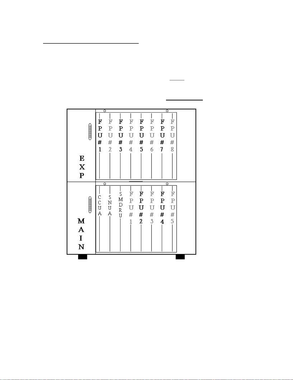
Using Figure 1 below locate where you will be installing the KDX-T1 card. You can
install the T1 card in FPU slots 2 or 4 in the main KSU and/or FPU slots 1,3,5 and 7 in
any one of the 3 expansion KSU’s.
Note: The slots to the immediate right of the T1 card cannot be used.
Figure: 1
If the KDX-T1 is installed in the wrong slot the Central Processor will not recognize
the card.
It is recommended that FPU #4 in the main and/or FPU #7 in the expansion(s) be
used for the KDX-T1 location. This will reduce the amount of switch cables needed
for your installation.
Note: Up to 4 T1 cards may be installed per KDX-500 system.
Page 3

Typical KDX-500 card configurations
The examples below show typical configurations and how the system assigns the T1
channels.
When the central processor identifies a KDX-T1 card it automatically treats it as if
there are 3 COU-A cards installed.
Example 1:
KDX-T1 card installed in FPU #4 = T1 Channels are C.O. ports 1 – 24 in system
programming.
Note: FPU #5 cannot be used.
Example 2:
COU-A card installed in FPU #3 = C.O. ports 1 – 8 in system programming.
KDX-T1 card installed in FPU #4 = T1 Channels are C.O. ports 9 – 32 in system
programming.
Note: FPU #5 cannot be used.
Page 4

KDX-500 SNU-A Jumper settings
Figure: 2
Before installing the KDX-T1 card the J1 and JP2 jumpers on the SNU-A card must
be set to the proper setting.
J1 should be set in the U-Law position.
JP2 must be in the T1 position.
Page 5

KDX-T1 Connections and Description
Figure: 3
D1- Status LED should flash under normal operation.
D2-9- T1 Board Alarms and Indicators should not light or flash under normal
operation. See T1 Alarms and Indicators for detailed description.
J1-J2 – Currently not supported.
J3- RJ-11 Test Jack can be used to test incoming and outgoing calls using channel 1.
J4- RJ-48 T1 main interface jack used to connect the T1 card to the Telco.
SW 4- Reset switch used to reset the T1 card, all calls will be dropped during reset.
SW5- Battery Back-up ON/OFF switch.
D1- Battery “ON” indicator, when LED is on the Memory will be retained during
power loss.
Page 6

KDX-T1 Dip Switch Location and Description
Figure: 4
SW1- Currently not used and should remain in the “OFF” position.
SW2- Used to setup Signaling parameters, see Dip Switch settings for proper
configuration.
Page 7

KDX-T1 Dip Switch Settings
SW-1
Currently not supported
SW-2 1- 8
Switch Position
Dip 1 ESF Framing D4 Framing
Dip 2 B8ZS Line Coding AMI Line Coding
Dip 3 Fixed Delay Dialing Wink Dialing
Dip 4 Loop Start Signaling Wink Start Signaling
Dip 5 FXS FSO
Dip 6 See next table See next table
Dip 7 See next table See next table
Dip 8 See next table See next table
ON OFF
SW-2 6-8
Dip 6 Dip 7 Dip 8 Line Build Out Application
OFF OFF OFF 0 to 133 Feet DSX-1/0 dB CSU
OFF OFF ON 133 to 266 Feet DSX-1
OFF ON OFF 266 to 399 Feet DSX-1
OFF ON ON 399 to 533 Feet DSX-1
ON OFF OFF 533 to 655 Feet DSX-1
ON OFF ON -7.5 dB CSU
ON ON OFF -15 dB CSU
ON ON ON -22.5 dB CSU
Page 8

Typical Dip Switch Settings for most installs
D4 AMI Loop Start FXS
1 2 3 4 5 6 7 8
OFF OFF OFF ON ON OFF OFF OFF
D4 B8ZS Loop Start FXS
1 2 3 4 5 6 7 8
OFF ON OFF ON ON OFF OFF OFF
ESF AMI Loop Start FXS
1 2 3 4 5 6 7 8
ON OFF OFF ON ON OFF OFF OFF
ESF B8ZS Loop Start FXS
1 2 3 4 5 6 7 8
ON ON OFF ON ON OFF OFF OFF
D4 AMI E&M Wink Start
1 2 3 4 5 6 7 8
OFF OFF OFF OFF OFF OFF OFF OFF
D4 B8ZS E&M Wink Start
1 2 3 4 5 6 7 8
OFF ON OFF OFF OFF OFF OFF OFF
ESF AMI E&M Wink Start
1 2 3 4 5 6 7 8
ON OFF OFF OFF OFF OFF OFF OFF
ESF B8ZS E&M Wink Start
1 2 3 4 5 6 7 8
ON ON OFF OFF OFF OFF OFF OFF
D4 AMI E&M Delay Start
1 2 3 4 5 6 7 8
OFF OFF ON OFF OFF OFF OFF OFF
D4 B8ZS E&M Delay Start
1 2 3 4 5 6 7 8
OFF ON ON OFF OFF OFF OFF OFF
Page 9

KDX-T1 Alarms and Indicators
Figure: 5
STATUS- Main Status LED should be flashing rapidly under normal operation.
LOS- When lit, indicates that the frame bit in the received data cannot be found.
RCL– This signal alarm turns on to indicate that the KDX has lost its incoming
signal.
YELLOW- A yellow alarm indicates the far end has lost synchronization to its
incoming signal.
BLUE- This alarm indicates that the far end has lost its receive signal (all 1 bits). The
purpose of this signal is to maintain the system clocks during a link failure.
TX CLK- This alarm indicates Loss of Transmit Clock.
SLIP- When lit, indicates a frame slip is detected. This is caused by the transmit
clock not being synchronized with the receive clock.
LOOP UP- Loop up code detected.
LOOP DOWN- Loop down code detected.
N/A- Not Assigned
Page 10

Connecting the T1 Trunk to the KDX-T1
Normally, the KDX-T1 card is connected to the Telco via a network interface box.
The box is usually small with an 8-pin modular telephone jack for connecting to the
customer premise T1 equipment (KDX-T1). Use a data-grade cable (Cat-5) with an 8pin modular plug for connection to the KDX-T1 card.
Make straight-through connections to pins 1,2,4 and 5 when using these plugs on both
ends. See KDX-T1 pin locations below.
Figure: 6
Note: The KDX-T1 card has been engineered to work with or without a customer
supplied CSU (Channel Service Unit).
 Loading...