

Page 1
Appendix E
KDX 60 Main MCB Card
The Main KSU provides for many connections to external devices as well as for the stations and
Trunks.
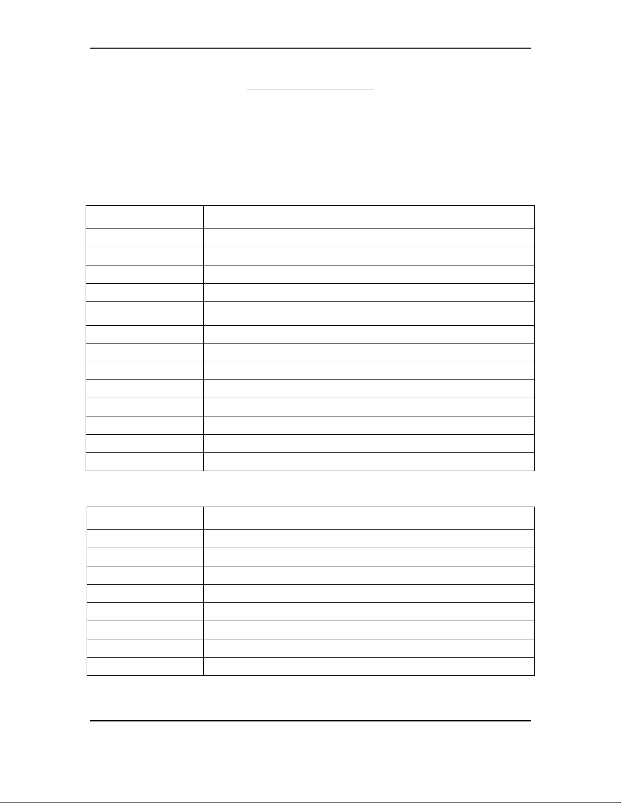
Connectors Description
JR1
JR2
JR4
JR5
JRC1 , JRE1 ,
JRA1 , JRG1
JR6
JR7
JR8
JR9
J1
J4 , J6 , J8 , J9
J2 , J4 , J6
J11 , J12
Note : without TDU Card should be plug in 10 pcs of mini Juper on J12.
Serial Port 1 used for SMDR / PC Programming
Serial Port 2 used for Voice Mail Integration
Relay Interface 1 & 2 (Programmable)
External Page & Music Source Interface
Digital Stations Ports 1 – 8
Trunk 1 & 2 RJ14 Interface
Trunk 3 & 4 RJ14 Interface
Single Line Ports 9 – 10
Single Line Ports 11 – 12
10-Pin Connector to Power Supply
Connector for Station Expansion Card (8 port)
Connector for Trunk Exp Card (4 line)
Connector for 12 KHz / 16KHz Tone Detector unit (Note)
Switches Description
SW1 Dip 1
SW1 Dip 2
SW1 Dip 3
SW1 Dip 4
SW1 Dip 5
SW1 Dip 6
SW1 Dip 7
SW1 Dip 8
Not Used
Ignore RTS & CTS on COM1
Not Used
Not Used
Not Used
“ON” = 3 Digit ICM numbering / “OFF” = 2 Digit ICM numbering
Not Used
Not Used
KDX System 60 Installation - 11 -
Page 2

Appendix E
Switches Description
SW2
SW3
Memory Back up Switch
System Reset Switch
LED Description
LED1 Memory Back-up Battery “ON” Indicator
LED2 CPU Status (Steady Flash indicates normal operation)
LED3 Single Line Ports 9 – 12 Ring Busy status.
LED4 Monitoring RS232 Data communication.
LED5 Monitoring RS232 Data communication.
LED6 Monitoring RS232 Data communication.
LED7 Monitoring RS232 Data communication.
See Figure 3 for connector, switches & LED locations.
KDX System 60 Installation - 12 -
Page 3

Appendix E
KDX System 60 Installation - 13 -
Page 4

Appendix E
Hardware Options
Backup Battery
The system power supply supports a backup battery package rated at 24 volts, 0.7 amperes/hour. A
trickle-charge maintains the battery at 95% efficiency, applies system cutover to battery when facility
power is removed, and provides system shutdown when battery power falls below a specified level.
External Music
Up to one (customer supplied) monaural music sources can be connected at the optional equipment
jack (JR5) located on the left side of the KSU. The connected music is available to the system only if
programmed using system Programming (PROG. 1-37 and 2-75) the impedance of the music source
must be 32ohms with power at approximately 100 milliwatts.
Note: An internal music source is available and is selected through system programming by default.
Note: In some circumstances there may be broadcast restrictions associated with the external music
source. Check with the sources original distributor and/or the radio station for copyright and
broadcast restrictions concerning background music and music–on-hold.
External Paging
The system supports a customer supplied amplifier for paging access to a single paging zone. The
amplifier can be connected at the optional equipment jack (JR5) located on the left side of the KSU.
Access is provided for 8 paging zones. The output for zones 1-7 must be connected through station
ports and must be assigned by system programming (PROG.3-35).
External Relays
The system supports 2 external relays for multiple functions such as station, trunk, loud-bell, Paging,
Music, and Door strike control. The customer supplied optional equipment can be connected at the
optional equipment jacks (JR4) located on the left side of the KSU. The contacts can be programmed
(PROG.3-40 and 3-41) for normally “open” or “closed” depending on customer needs.
Caller I.D.
The system supports Caller I.D. offering Name or Number display. The caller I.D feature is
programmed in the system database (PROG.1-05, 2-26 and 2-73). Caller I.D. number is reported to
SMDR print-out (see figure 6).
KDX System 60 Installation - 14 -
 Loading...