

Page 1

ATLAS EX 60
DIGITAL BUSINESS SYSTEM
INSTALLATION MANUAL
KS Telecom
W. Palm Beach FL.
Page 2

ATLAS EX 60 Installation
Introduction ................................................................................................2
FCC Requirements .....................................................................................................................................2
Related Documents ....................................................................................................................................2
Incidence of Harm......................................................................................................................................2
System Specifications .................................................................................3
General Description ...................................................................................3
System Summary .......................................................................................................................................5
Equipment Summary..................................................................................................................................6
Numbering Scheme....................................................................................................................................6
ATLAS EX 60 Main MBU Card ...............................................................................................................8
Hardware Options....................................................................................10
Backup Battery.........................................................................................................................................10
External Music .........................................................................................................................................10
External Paging ........................................................................................................................................10
External Relays ........................................................................................................................................10
Caller I.D. .................................................................................................................................................10
Voice Mail. ...............................................................................................................................................10
Serial Ports ...............................................................................................................................................13
SMDR Printout.........................................................................................................................................14
Installation Procedures............................................................................15
Precautions ...............................................................................................................................................15
Handling Static-Sensitive Devices...........................................................................................................15
Installing Station Wiring ..........................................................................................................................15
Connecting Power Cords .........................................................................................................................16
Site Requirements ....................................................................................................................................16
Power Surge Protector Ground ................................................................................................................17
Telephone Line Power Surge Protection .................................................................................................17
Unpacking and Inspecting........................................................................................................................17
Main Cabinet (KSU) Installation.............................................................................................................19
Trunk Connections...................................................................................................................................21
Single-line Phone Wiring.........................................................................................................................23
Keyphone Wiring .....................................................................................................................................23
Installing the Keyphones..........................................................................................................................23
Wall Mount a Keyphone ..........................................................................................................................24
DSS Installation........................................................................................................................................24
BATU UNIT.............................................................................................................................................25
ATLAS EX 60 System Power Supply .....................................................................................................28
Backup Battery.........................................................................................................................................28
MEMORY BACKUP SWITCH ..............................................................................................................30
ATLAS EX 60 Installation - 1 -
Page 3

ATLAS EX 60 Installation
Introduction
This section describes the ATLAS EX 60 Digital Business System, a small telecommunications
system that provides voice communications with a wide range of features. An overview of the system
equipment is presented: followed by instructions for installing the system and station equipment and
for connecting optional devices supported by the system. System specifications are grouped for a
quick reference guide.
This equipment can be used with telephone company equipment that accepts pulse or DTMF dialing.
The equipment has been assigned an FCC registration number under Part 68.
For direct connection to the telephone network, the equipment must be installed as described, and the
FCC registration must be reported to the local telephone company.
FCC Requirements
The ATLAS EX 60 Digital Communication System is FCC-registered as a fully protected key system
under Registration Number – PENDING, Ringer Equivalence 0.2a
Related Documents
For additional information regarding station feature operation, refer to the Easy reference guide
included with each Digital set.
For details related to changing system database, refer to ATLAS Series 500 Programming guide.
Note:
To maximize user satisfaction and to minimize service calls, it is strongly recommended that all users
be instructed in station operation and that every station user be provided with a copy of the Easy
Reference Guide.
Incidence of Harm
When practical, the telephone company must inform the customer that the service may be
temporarily discontinued if the equipment he is using should cause harm to the telephone network.
The telephone company must attempt to inform the customer that the service is to be discontinued
prior to actually terminating service. The telephone company must also provide customers with
opportunity to correct the problem and must advise customers of their right to bring compliant
procedures before the FCC.
ATLAS EX 60 Installation - 2 -
Page 4
ATLAS EX 60 Installation
System Specifications
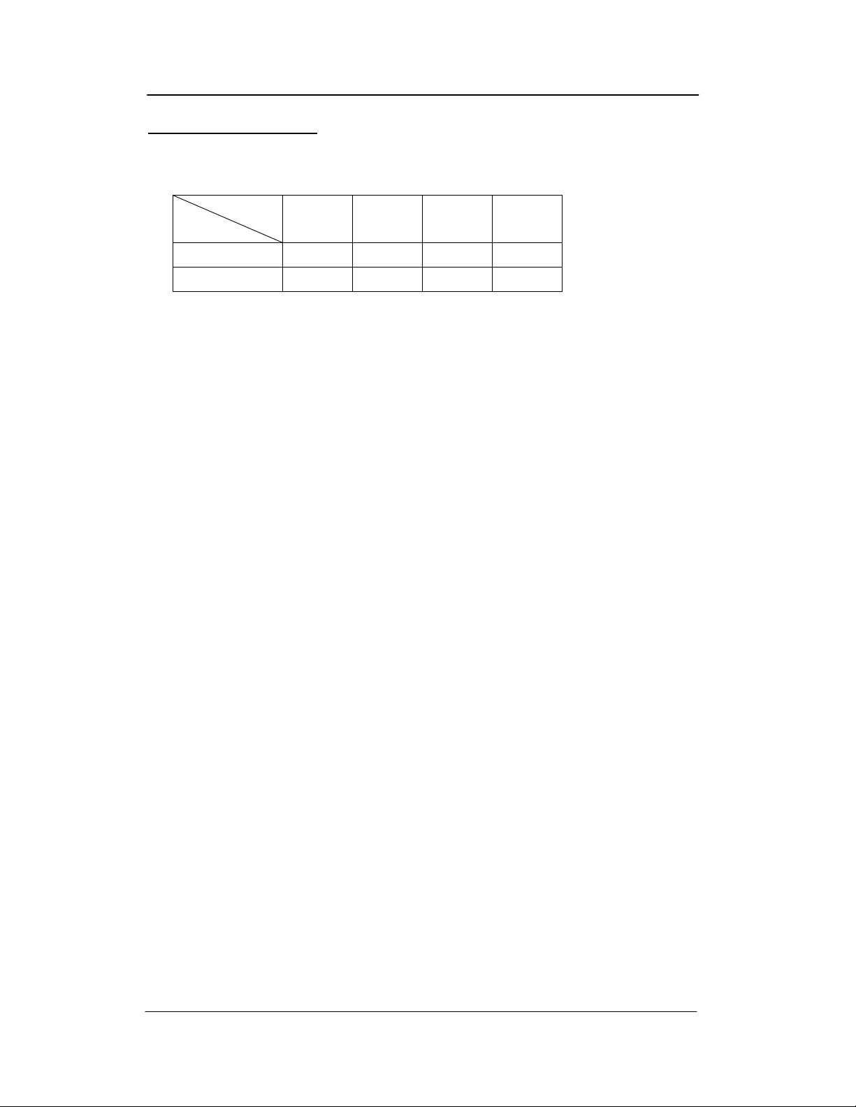
System Capacity: Cabinet
Line
Name
Trunk Lines 4 12 8 16
Stations 12 36 44 28
Power Requirements:
Input Voltage: 110 ± 10 Volt AC, 50/60 Hz, single phase, or 220 V ± 10 Volt AC by Switchable.
Environmental Conditions:
Surrounding temperature: 0-40°C
32-104°F
Surrounding humidity: 10-90 %
Cable Requirements:
Digital Phone: Station Cable, 1 pair twisted wire.
Station loop resistance = 40 ohms max.
Single-Line Telephone: Station cable, 1 pair (2 wires).
Station loop resistance = 800 ohms max.
Basic Max A Max B Max C
Cable Length:
Digital Phone: See Page 24 Fig. 13
Single-Line Telephone: See Page 24 Fig.12
Communication Links:
Digital switching
Electret transmitter
Dynamic Receiver
Circuitry Control:
16-bit 8830 microprocessor
ATLAS EX 60 Installation - 3 -
Page 5

ATLAS EX 60 Installation
Number Dialing Requirements:
1) Pulse Dial
Speed: 10 or 20pps
Ratio: 60 ± 3% or 67 ± 3%
Pause: 1800ms
2) DTMF
A) Frequency range: High Group 1209Hz, 1336Hz, 1477Hz
.Low Group 697Hz, 770Hz, 852Hz, 941Hz
B) Frequency uncertainty: 1.5% and less
C) Tone Level: Low level –10dBm ± 2dBm
High level –8dBm ± 2dBm
3) Duration: 70ms
4) Digit Period: 70ms
5) Memory Dial: Last Number Redial, Save Number Redial & Speed Dial
6) System speed dial: 400 numbers (100-499)
7) Station speed dial: 9 numbers
Power Failure:
An optional backup battery can be installed for power outage prevention. Length of time usually
depends on battery capacity. During most communication situations 2-12 Volt 10amph batteries in
series can be used. Battery charger is built in.
ATLAS EX 60 Installation - 4 -
Page 6

ATLAS EX 60 Installation
General Description
This part provides an overview of the system equipment, including descriptions of cabinet, cards, and
station instruments.
Note: The system’s programmed database is changed using Three Programming Sections with 99
two-digit MODE numbers per section. Each MODE number represents a changeable feature or
function parameter. The Section and Mode numbers are referenced throughout the descriptions in this
document (e.g. PROG.1-37 = Section 1, Mode 37) to allow quick access to programming information
when required for clarity. Instructions for using Mode numbers to change the database are contained
in the Series 500 Programming Guide.
System Summary
The ATLAS EX 60 is a Digital Communication system that operates like a Key System or as a
multifunctional PABX, depending on database programming. System operation is controlled by a 16-
bit 8830 microprocessor. Digital switching uses CMOS technology to assure non-blocking operation.
The 8830 microprocessor performs all logical operations and passes control signals to other circuits
in accordance with system demands. Microprocessors located in each Digital Phone in the system
communicate with the system controller for operational control.
System and station feature operations and selected system functions are controlled by a stored
program database. The database in default state is stored in on-board EPROM. The default database
is copied to battery-protected RAM during system initialization. It supports a fully operational
system. Values in the RAM-based data can be changed as needed.
The system can be configured 52 ports with 16 Trunks, 24 Digital stations and 4 Single-Line
telephones. Regardless of capacity used the system remains non-blocking with consistent voice
quality.
The system supports ATLAS 1-pair Digital keyphones and industry-standard single-line phones
(with electronic ringers). One Digital Display phone is required for system programming. 64 Button
Digital DSS consoles can be equipped to operate as a companion to Digital keyphones. Each console
occupies one digital port.
The ATLAS Digital keyphones are available in LD40 (6-line by 20-character Display) and DT 36
/ DB type button models. The DT 36 / DB type button is available with a 2-line by 16-character
Display. All ATLAS Digital keyphones are headset compatible.
Equipment Summary
ATLAS EX 60 Installation - 5 -
Page 7

ATLAS EX 60 Installation
The Main equipment cabinet is modular in design. It houses the power supply and the MBU Unit.
The power supply occupies the bottom portion of the cabinet; the MBU card occupies the remainder
of the cabinet. The MBU Unit controls system operation, 4 Trunks, 8 Digital ports and 4 single-line
ports. An Expansion card can be added which supports an additional 2 BRI, 4 TKU, 8 DSU and 8
SLU.
The power supply is a wired–in unit. The outputs are +5 Volts at 3amps, -28 Volts at 4amps and –60
Volts 1amp. Full control is available for a customer-supplied backup battery, including trickle-charge
capabilities.
Note: SLP ring voltage is 45VAC (rms) and will not support Mechanical type ringers.
Trunk interface circuits support Loop-start trunk applications. Trunk lines connect to the MBU card
through card-edge-mounted modular jacks.
Digital keyphones and Single-line telephones connect to the MBU through a card-edge-mounted RJ-
11 or Quick.
Options available and supported by the system include:
1-programmable external music source interfaces
1-external page port interface
2-programmable external relay interfaces
2-serial port interfaces
1-connecting terminals and control circuit for backup batteries
Numbering Scheme
Station and Trunk Port numbers are fixed and cannot be changed. Station extension numbers are
assigned in the default database but can be changed by system programming (PROG.2-70). Default
station numbers are 10 – 45. One, two, three or four digit station numbers can be programmed. The
system does not allow conflicts in station number assignments (i.e. station number 20 and station
number 200), but does allow the same number to be assigned to more that one port, when this occurs
only the lowest numbered port can be called on intercom.
Dial access codes are used at keyphones and single-line phones to access features. At keyphones, all
features can be accessed by fixed feature buttons, programmable softkeys, or by dial access codes.
The feature access codes are listed in Table A.
ATLAS EX 60 Installation - 6 -
Page 8

ATLAS EX 60 Installation
TABLE A
DIAL ACCESS CODES FOR IDLE STATION
DIAL ACCESS CODES FEATURE
1-6999
1-7*
1-7#
71 + Station No.
72 + Station No.
71* + Station No.
72* + Station No.
73 + Station Hunt Group No.
739
741 + HHMM
742 + HHMM
743 + Station No.
744
745
746 + 01-09
747
748
749 + Lock Code
740 + Station No.
74#
75 + Station No.
76 + 0-9
77 + Trunk No.
78 + Station Hunt Group No.
70 + Speed Dial Bin
70 00
70#
8
9,91-98
0
*
# + 1-8
#9
Station Intercom Dialing
Station Group call Pickup
Page keyphone group
Call Forward All Calls
Call Forward Busy/No Answer
All Calls Follow Me
Busy/No Answer Follow Me
Ring all Stations in Group
Voice Mail Main Greeting
Daily Alarm
Once only Alarm
Message Wait activate
Message Wait respond
Answer Paging call
Personal Speed Dial
Do Not Disturb
SLP Conference
Phone Lock
Message Wait clear
Station Caller ID History
Hold Pickup
Call Park/Call Park Retrieve
Access Outside Line
Station Hunt Groups (1-8)
System/Personal Speed Dial
Redial
Redial
Trunk Hunt Group 8
Trunk Hunt Groups 1–8
Call Operator
System Call Pickup
Page External Zone 1-8
Page all internal
ATLAS EX 60 Installation - 7 -
Page 9
ATLAS EX 60 Installation
#0
#*
1
#
Page all external
Page all internal/external
Music over external page ( #0 or #* )
Background music
ATLAS EX 60 Main Board Unit (MBU)
The Main KSU provides for many connections to external devices as well as for the stations and
Trunks.
Connectors Description
JR1 Serial Port 1 used for SMDR / PC Programming
JR2 Serial Port 2 used for Voice Mail Integration
JR4 Relay Interface 1 & 2 (Programmable)
JR5 External Page & Music Source 1 & 2 Interface
JRC1 , JRE1 ,
JRA1 , JRG1
JR6 Trunk 1 & 2 RJ14 Interface
JR7 Trunk 3 & 4 RJ14 Interface
Digital Stations Ports 1 – 8
JR8 Single Line Ports 9 – 10
JR9 Single Line Ports 11 – 12
J1 10-Pin Connector to Power Supply
J4 , J6 , J8 , J9 Connector for Station Expansion Card (8 port)
J2 , J4 , J6 Connector for Trunk Exp Card (4 line)
J11 , J12 Connector for 12 KHz / 16KHz Tone Detector unit (Note)
Note : without TDU Card should be plug in 10 pcs of mini Juper on J12.
Switches Description
SW1 Dip 1 Not Used
SW1 Dip 2 Ignore RTS & CTS on COM1
SW1 Dip 3 Not Used
SW1 Dip 4 Not Used
SW1 Dip 5 “ON” = Pulse Dialing / “OFF” = DTMF Dialing
SW1 Dip 6 “ON” = 3 Digit ICM numbering / “OFF” = 2 Digit ICM numbering
SW1 Dip 7 “ON” = A-Law / “OFF” = µ-Law
SW1 Dip 8 Not Used
ATLAS EX 60 Installation - 8 -
Page 10

ATLAS EX 60 Installation
Switches Description
SW2 Memory Back up Switch
SW3 System Reset Switch
LED Description
LED1 Memory Back-up Battery “ON” Indicator
LED2 CPU Status (Steady Flash indicates normal operation)
LED3 Single Line Ports 9 – 12 Ring Busy status.
LED4 Monitoring RS232 Data communication.
LED5 Monitoring RS232 Data communication.
LED6 Monitoring RS232 Data communication.
LED7 Monitoring RS232 Data communication.
See Figure 1 Mother Board
ATLAS EX 60 Installation - 9 -
Page 11

ATLAS EX 60 Installation
Hardware Options
Backup Battery
The system power supply supports a backup battery package rated at 24 volts, 0.7 amperes/hour. A
trickle-charge maintains the battery at 95% efficiency, applies system cutover to battery when facility
power is removed, and provides system shutdown when battery power falls below a specified level.
External Music
Up to one (customer supplied) monaural music sources can be connected at the optional equipment
terminal (JR5) located on the left side of the KSU. The connected music is available to the system
only if programmed using system Programming (PROG. 3-37 and 2-75) the impedance of the music
source must be 32ohms with power at approximately 100 milliwatts.
Note: An internal music source is available and is selected through system programming by default.
Note: In some circumstances there may be broadcast restrictions associated with the external music
source. Check with the sources original distributor and/or the radio station for copyright and
broadcast restrictions concerning background music and music–on-hold.
External Paging
The system supports a customer supplied amplifier for paging access to a single paging zone. The
amplifier can be connected at the optional equipment terminal (JR5) located on the left side of the
KSU. Access is provided for 8 paging zones. The output for zones 1-7 must be connected through
station ports and must be assigned by system programming (PROG.3-35).
External Relays
The system supports 2 external relays for multiple functions such as station, trunk, loud-bell, Paging,
Music, and Door strike control. The customer supplied optional equipment can be connected at the
optional equipment terminals (JR4) located on the left side of the KSU. The contacts can be
programmed (PROG.3-40 and 3-41) for normally “open” or “closed” depending on customer needs.
Caller I.D.
The system supports Caller I.D. offering Name or Number display. The caller I.D feature is
programmed in the system database (PROG.1-05, 2-26 and 2-73). Caller I.D. number is reported to
SMDR print-out (see Figure 4).
Voice Mail.
The system can be equipped with an optional 4 port Voice Mail Card mounted over the main MBU
board. The Voice Mail connects internally to the Communications Bus via ribbon cable connected to
J10 located in the lower left corner of the main MBU and the integration cable to COM2 (JR2)
located on the right side of the main MBU. See Figure1.
For programming the Voice Mail uses software ports 21-24 when configured 8 x 16 x 4 and software
ports 37-40 when configured 8 x 32 x 4.
ATLAS EX 60 Installation - 10 -
Page 12

ATLAS EX 60 Installation
J11
J10
TO 2-W Digital Telephone
(D.T)
TO Single Line Telephone
(SLT)
TO Voice mail card.
JRC1
JRA1
3,4
1,2
JR8
3,4
JR9
1,2
7,8
5,6
J9
JRG1
JRE1
DSU / SLU
J8
J6
Internal music
Volume control
VR1
LED2
TKU / DSU / SLU
J4
LED1
SW1
1 2 3 4 5 6 7 8
ON
OFF
J2
TKU
LED3
Battery
ON
Memory
Backup
SW3
Battery
LED6
LED4
System
Reset Button
Back-up
SWITCH
OFF
SW2
Figure 1 : MBU Card
J12
10 14 18 22 26 30
1 5 9 13 17 21 25 29
2 6
3,4
JR7 JR6
TO C.O Line (TKU)
1,2
EXT.
JR5
JR4
power control
LED7
LED5
JR1 JR2
Paging
EXT.
music
source
To
Loud
Bell
To
EXT.
Music
COM2
RS232
COM1
ATLAS EX 60 Installation - 11 -
Page 13

ATLAS EX 60 Installation
JR5
External paging output
External paging output
External music source
External music source
JR4
Relay 1 for Loud Bel
Relay 1 for Loud Bel
Relay 2 for External music
Relay 2 for External music
Figure 2 : Optional Equipment terminal PIN Functions
ATLAS EX 60 Installation - 12 -
Page 14

ATLAS EX 60 Installation
Serial Ports
The system supports 2 serial ports COM1 and COM2, COM1 is used for PC programming and
SMDR (see Figure.3) and COM2 accessible only from the inside is used for Voice mail integration.
They are card-edge-mounted modular jacks located on the bottom side of the cabinet. They are
labeled JR1 and JR2. The distance between the data device and the common equipment can be up to
100 feet in a quiet electrical environment. Shielded cable may be required for some runs. For longer
distances, a customer supplied serial extender may be used to relay the data communications between
the common equipment and the data devices.
Baud rate = 2400bps; data bits = 8; stop bits = 1; parity = none.
(COM2)
(COM1)
Figure 3 : Serial Port Jack Pin Functions
ATLAS EX 60 Installation - 13 -
Page 15

ATLAS EX 60 Installation
SMDR Printout
ST TK TELEPHONE NO. TRF ACC.NO. DATE START DURATION RING
10 05 5156310 113 04/01 09:15 00:01:05
16 04 15618400636 04/01 09:18 00:04:56
****
08 #################### 04/01 09:37 00:12
26 01 # 5615156300 04/01 10:02 00:14:30 00:06
****
02 # 5615156301 04/01 10:03 00:54
12 09 1305551212 254 04/01 10:18 00:04:18
17 <STATION ALARM> 04/01 13:00
COLUMN CONTENT EXPLANATION
1 ST STATION NUMBER
2 TK TRUNK NUMBER
3
TELEPHONE
NO.
4 TRF ENTRY DENOTES A TRANSFERRED CALL
5 ACC.NO. OPTIONAL CALLER DIALED ACCOUNT CODE
6 DATE DATE OF THE CALL RECORD- MM:DD
7 START TIME OF DAY CALL STARTED- HH:MM
8 DURATION LENGTH OF CALL- HH:MM:SS
9 RING RINGING TIME FOR INCOMING CALLS- MM:SS
TELEPHONE NUMBER CALLED. *REPRESENTS AN
INCOMING CALL. STATION ALRMS ARE ALSO NOTED HERE.
Explanation of Example Entries:
1. On 04/01 at 09:15 AM Station 10 seized trunk 5 and made an outside call to 5156310. The call
lasted for 1 minute and 5 seconds. Before being transferred.
2. On 04/01 at 09:18 AM Station 16 seized trunk 4 and made an outside call to 15618400636. The
call lasted for 4 minutes and 56 seconds.
3. At 09:37 AM an incoming call rang and was not answered. There was no Caller ID.
4. An incoming call rang on trunk 1 for 6 seconds from 5615156300 was answered by station 26. The
call lasted 14 minutes and 30 seconds.
5. An incoming call rang on trunk 2 for 54 seconds from 5615156301 and went unanswered.
6. An outgoing call to 13055551212 on trunk 9 by station 12 lasted 4 minutes and 18 seconds during
which time the station user entered an Account code 254.
7. At 1:00 PM a station alarm rang at Station 17.
Figure 4: SMDR Call Records and Explanations
ATLAS EX 60 Installation - 14 -
Page 16

ATLAS EX 60 Installation
Installation Procedures
This part contains the procedures for installing the ATLAS EX 60 Digital Business System.
Precautions for personnel and equipment safety and installation prerequisites are provided before
detailed instructions for installing the equipment cabinet, connecting ground, installing and wiring
station cross-connect blocks, connecting Trunk lines, and installing station equipment.
Precautions
The following paragraphs explain the precautions to be observed for handling, installing, and
working with system equipment and components.
Handling Static-Sensitive Devices
WARNING: The system contains static-sensitive components. Personnel
who are required to handle Printed Board Assemblies (PBA’s), components, or
wiring must have knowledge of proper handling techniques.
The human body can easily accumulate a high voltage charge of static electricity. Precautions must
be taken to prevent this charge from damaging static-sensitive components. The following are
standard handling precautions for static sensitive devices:
Touch the cabinet to dissipate any stored charge immediately before removing, inserting, or
otherwise handling a PBA.
Hold the PBA by its edges and avoid touching component pins or connectors.
Cover work surfaces with conductive material connected to earth ground. A ground clip connected to
a static-protective shipping bag provides an adequately protective work surface.
Use flexible ground straps to continuously discharge static electricity.
Store PBA’s in static-protective shipping bags.
Installing Station Wiring
DANGER: TO REDUCE RISK OF ELECTRICAL SHOCK AND PERSONAL
INJURY, USE CARE WHEN INSTALLING STATION WIRING.
Observe the following precautions when installing station wiring:
ATLAS EX 60 Installation - 15 -
Page 17

ATLAS EX 60 Installation
Never install telephone wiring during a lightning storm.
Never install telephone jacks in wet locations unless the jack is specifically designed for wet
environments.
Never touch un-insulated telephone wire or terminals unless the telephone line has been disconnected
at the network interface.
Use caution when installing or modifying telephone lines.
Connecting Power Cords
WARNING: Do not attach power supply cords to building surfaces.
The basic system is furnished with a detachable power supply cord that is configured for connecting
to a branch circuit receptacle equipped with a third wire ground. The cord should be dressed for
appearance and safety, but never attached to the building surface.
Site Requirements
The selection of a suitable location is essential when installing the key service unit (KSU). The area
should be clean, dry, static-free, temperature controlled, and accessible only to authorized personnel.
When selecting a site, give careful consideration to the following:
Ample space must be allowed to mount the cabinet and MDF (Main Distribution Frame) and to allow
for removal of the KSU cover to access assemblies and cards within the cabinet.
A well-ventilated and well-lighted area with a temperature range of 32-100° F (0-40° C) and 10%-
90% relative non-condensing humidity. The area must not be exposed to direct sunlight, heat or dust.
Optimal temperature range is 40-70° F.
A dedicated 110/220 Volt AC, 15 Amp, 50/60 Hz, single phase, 3 wire, and parallel blade with
ground power outlet should be located within 2 metres of the KSU. Additional outlets for music
source, paging amplifier, etc. as needed. The AC receptacles must be third-wire grounding type.
The third-wire ground must be connected to an approved earth ground through the single-point
grounding circuit at the power distribution panel.
Avoid areas that produce radio frequency interference (RFI) or electro-magnetic interference (EMI).
(E.g. electric welding equipment, radio frequency transmitters, magnets, refrigerators, copy
machines, microwave ovens, etc.)
ATLAS EX 60 Installation - 16 -
Page 18

ATLAS EX 60 Installation
Locate the KSU and stations so as to minimize cable length. All station cables must be 1-pair
twisted-pair cable and must be home run. The Digital Keyphone may be wired differently.
Cabling lengths must not exceed the following:
Digital phone: using 24 gauge – 1000 feet depending upon wiring configuration.
Single-Line Telephones: using 24 gauge – 5000 feet.
The Trunk lines connect to the system through modular jacks located on the left side of the KSU.
Central Office terminations should be within 6 feet of the cabinet/main distribution frame.
Make sure there is a good earth ground utilizing #12 AWG or larger standard, copper wire within (8
metres) of the KSU. A metallic COLD water pipe usually provides a reliable ground path.
Carefully check that the pipe does not contain insulated joints that could isolate the ground. (The
pipe must be metallic from the point of ground to the connection to the water main outside the
building).
Warning: To avoid equipment damage, do not attempt to connect or operate the equipment before
proper ground has been installed.
Power Surge Protector Ground
Power surge protectors must be grounded either to the approved earth ground or an equally adequate
but separate grounding system. Install ground wires of the size specified by the manufacturer
between the line protector devices and the earth ground connection. Be sure to connect the ground
wire at a point closer to true earth ground than the AC distribution panel single-point ground wire
and the chassis ground wire connections. Secure the attaching clamp.
Telephone Line Power Surge Protection
System equipment must be protected against power surges on all externally connected telephone
lines. This includes protecting lines coming into the building from the telephone company, lines
going out of the building to off-premises stations located in an adjacent building, and lines going into
the adjacent building that houses the off-premises stations.
Unpacking and Inspecting
The following paragraphs provide directions for unpacking and inspecting the system components.
ATLAS EX 60 Installation - 17 -
Page 19

ATLAS EX 60 Installation
WARNING: The system equipment contains static sensitive components. Personnel who are required
to handle components or wiring must have knowledge of proper handling techniques and must have
the necessary safeguard equipment for protecting static-sensitive devices. Refer to PRECAUTIONS.
All equipment is packaged in corrugated cardboard containers. All equipment options are packaged
separately in individual cartons. Each telephone is packaged separately in an individual carton.
However, an outer slip or larger container may be used to group quantities of telephones.
Check all items received against the packing slip. Examine cartons for visual signs of damage. If
cartons appear too be damaged, make a note of such damage on the packing slip and on the carrier
way bill, if available.
Open the carton containing the system equipment. Remove the packaging material from the carton.
Remove the cabinet and lay it face–up on a level work surface. Remove all packaging material.
Check the exterior cabinet. Make a note of any damages.
Observing electronics equipment handling precautions, remove each piece of equipment from its
shipping container. As each item is unpacked, place it on a level work surface. Remove packaging
material and inspect the equipment for physical damage. Make a note of any damages.
Report all damages noted to your supplier.
ATLAS EX 60 Installation - 18 -
Page 20

ATLAS EX 60 Installation
Main Cabinet (KSU) Installation
When mounting the KSU, care should be taken to mount the equipment so that all cables and AC
cords are neatly arranged. The KSU should not be mounted directly of masonry, concrete, or other
wall surfaces subject to moisture or condensation. (Use plywood backup board when mounting on
these types of surfaces). Locate the four mounting hardware screws as shown by FIGURE 6. The
recommended screw size for attaching the cabinet wall mounting brackets on a 20 mm (3/4 inch)
plywood backboard is 6 mm x 38 mm (# 8 x 1.5 inch) pan-head screws. The slots for hanging the
cabinet are located on the back of the cabinet. The power switch and power cable should be at the
lower left of the cabinet. Once the mounting plate is attached to the wall or prepared backboard,
simply hang the unit on the wall.
Immediately after mounting the KSU, the system must be properly grounded. The AC line cord
(green conductor) is not always a reliable earth ground, it should not be used as the required ground.
There is a ground port beside the cabinet for ground wiring. Refer to Figure 5.
The AC connection to the power supply requires a parallel blade with a ground receptacle. A three to
two wire isolation adapter should not be used. To ensure proper system operation, a good earth
ground should be provided. In most cases, this can be provided by a metallic cold water pipe. Earth
ground should be provided using 16 AWG or larger with a surge protector to provide clean unfiltered
power and to protect against high voltage. The cleaner the power, the longer the system will last.
Figure 5 : GROUNGING POST
ATLAS EX 60 Installation - 19 -
Page 21

ATLAS EX 60 Installation
Figure 6 : HOW TO WALL MOUNTING
Installation of Cards
WARNING!! TURN OFF THE POWER BEFORE INSERT OR REMOVE CARDS!!
To insert a card:
Push lightly until the male connectors surely into the female receptacles on MB. Once the pins and
receptacle are connected correctly, push on both ends simultaneously to insure good connection.
To remove a card:
Remove the card by pulling up the both ends of it simultaneously.
ATLAS EX 60 Installation - 20 -
Page 22

ATLAS EX 60 Installation
Trunk Connections
All trunk connections are made on the left side of the cabinet. (See Figure 1) Two lines are connected
through each modular jack. Refer to Figure 7 for modular jack or Quick Connector pin functions.
Install a modular line cord between each trunk terminating modular wall jack and the corresponding
jack on the side of the cabinet.
CO 4 Tip
CO 3 Tip
CO 3 Ring
CO 4 Ring
CO 2 Tip
CO 1 Tip
CO 1 Ring
CO 2 Ring
JR7
(RJ11 Modular Jack)
JR6
(RJ11 Modular Jack)
OR
JR7
(Quick Connector)
JR6
(Quick Connector)
Figure 7 : Typical Trunk Connecting Jack Pin Functions
CO 4 Tip
CO 3 Tip
CO 3 Ring
CO 4 Ring
CO 2 Tip
CO 1 Tip
CO 1 Ring
CO 2 Ring
ATLAS EX 60 Installation - 21 -
Page 23

ATLAS EX 60 Installation
How to Use the Quick Connector
Insert the necessary wires into the guiding holes on the top of the connector. The PVC covering wires
can be seen as they reach the bottom of the guiding holes. Press the quick connector from both sides,
then the wires will be clipped and stripped by the blades inside. Try to pull the wires out to make sure
that they are fixed and attached. Please refer to FIGURE 8.
3
Figure 8 : QUICK CONNECTOR
JRG1
(RJ11 Modular Jack)
JRE1
(RJ11 Modular Jack)
(Quick Connector)
(Quick Connector)
Station 8 Tip
Station 7 Tip
Station 7 Ring
Station 8 Ring
Station 6 Tip
Station 5 Tip
Station 5 Ring
Station 6 Ring
(RJ11 Modular Jack)
(RJ11 Modular Jack)
JRC1
JRA1
OR
JRG1
JRE1
Station 8 Tip
Station 7 Tip
Station 7 Ring
Station 8 Ring
Station 6 Tip
Station 5 Tip
Station 5 Ring
Station 6 Ring
(Quick Connector)
(Quick Connector)
JRC1
JRA1
Figure 9 : Typical Station Connecting Jack Pin Functions
Station 4 Tip
Station 3 Tip
Station 3 Ring
Station 4 Ring
Station 2 Tip
Station 1 Tip
Station 1 Ring
Station 2 Ring
Station 4 Tip
Station 3 Tip
Station 3 Ring
Station 4 Ring
Station 2 Tip
Station 1 Tip
Station 1 Ring
Station 2 Ring
ATLAS EX 60 Installation - 22 -
Page 24

ATLAS EX 60 Installation
Single-line Phone Wiring
Each quick connector supports either one Keyphone or one single-line phone. Single-line phones can
use a cable length of up to 1500m (5000 feet) using 24 gauge cable. As to connect a single-line phone,
only to connect the two pins, TIP and RING. Please refer to Figure 9.
Keyphone Wiring
All stations are lines run to common 66 type connection blocks. Keyphones require 1 pair industry
standard twisted cable. The maximum cable length is 300m (1000 feet) when using 24 gauge wire.
Please refer to Figure 9.
CAUTION !!!
z Never install telephone wiring during lightning storm.
z Never install telephone jacks in wet locations unless the jack is specifically designed for wet
locations.
z Never touch uninsulatted telephone wires or terminals unless the telephone line has been
disconnected at the network interface.
z Use CAUTION when installing or modifying telephone line.
z Some guidelines for running station cable:
z AVO ID cable runs parallel to fluorescent light fixtures or AC lines not in conduit. If these
obstacles are unavoidable. Run the cable across them at right angles.
z DO NOT run station cables inside electrical conduit already occupied by AC power cable.
z DO NOT run station cables near equipment with electric motors or past strong magnetic fields.
(copy machines, heavy motors, welding equipment, etc)
z DO NOT place station cables where they can be stepped on, or rolled over by office chairs or
desks.
Installing the Keyphones
1. Unpack and inspect each Keyphone for damage. Along with Keyphone, the box should contain
a 1.8m (5.9 feet) line cord, a coiled handset cord and a handset.
2. With the KSU AC power on, check for the correct voltage (24-Volts) across the black and
yellow terminals on each modular jack assembly.
3. Install the Keyphones by plugging the 1.8m (5.9 feet) base cord into the back of the Keyphone
and also into the modular jack assembly in the wall.
ATLAS EX 60 Installation - 23 -
Page 25

ATLAS EX 60 Installation
Wall Mount a Keyphone
The base plate is mounted by attaching two screws to the base of the unit. Once secured, drive a #8
pan-head screw (or proper hardware for the wall) into the center of each mounting hole marking. The
head of the screw should protrude approximately 6 to 12 mm (0.2 to 0.4 inch).
Mount the Keyphone on the wall. Adjust the screws if necessary to ensure that the Keyphone is
securely mounted, and adjust the handset clip. For a clear demonstration, please refer to FIGURES
10 & 11.
Figure 10 : WALL MOUNT THE KEYPHONE Figure 11 : ADJUST THE CLIP
DSS Installation
The DSS unit requires a digital phone port just as the digital phone does. Observe Dipswitch settings
on bottom of DSS.
The DSS is always installed in the next highest physical digital phone port from the phone that will
work with it. (E.g. Digital phone port11 / DSS must be port 12)
It is possible to install more than one DSS with one digital phone. (E.g. If Digital phone is port 23 /
DSS (1) must be port 24, DSS (2) must be port 25)
ATL AS
EX 60
1 Pair
Figure 12: Single Line Telephone cable length
ATLAS EX 60 Installation - 24 -
Page 26

ATLAS EX 60 Installation
Digital Phone Cable Length
ATL AS
EX 60
1000 FEET (24 gauge)
1 Pair
Figure 13: Digital Phone cable length
BATU UNIT
The BATU Unit provides the capability to connect external batteries to the system to provide for
complete system operation in the event of local power failure. Attach batteries
(24 VDC) to the BATU Unit at the appropriate terminals. (See Figure 19) The system applies a
trickle charge to the battery when it is not in use.
Keep the battery(s) dry and clean. Avoid damp wet areas or areas where the battery may be easily
damaged. Wires should run from the battery(s) to the terminals on the BATU Unit. When connecting
to the BATU, pay particular attention to matching the positive and negative connections. Improper
connection will damage the power supply. When operating from the battery, the system will
automatically cut off the power supply from the battery when the voltage gets too low, so that the
battery can be recharged.
CAUTION!!!! To reduce the risk of fire or injury please note the following:
Do not dispose of the battery(s) in a fire. The cell may explode. Check with local codes for special
disposal instructions.
Do not open or mutilate the battery(s). Released electrolyte is corrosive and may cause damage to the
eyes or skin. It may be toxic if swallowed.
Exercise care in handling the battery(s) in order not to short the battery with conducting materials
such as rings, bracelets and keys. The battery may overheat and cause burns.
Observe proper polarity orientation between the battery(s) and BATU Unit.
Do not mix battery(s) of different sizes or from different manufacturers in this product.
The length of time system operation is maintained under battery power depends on battery capacity.
Typical system support for the 24 Volt battery(s) is approximately one hour.
ATLAS EX 60 Installation - 25 -
Page 27

U
ATLAS EX 60 Installation
TKU (Trunk Unit)
The system provides 3 slots for trunk interface card. Each TKU contains 4 analogue trunk interface
circuits for loop-start applications. It supports both DTMF and Pulse dialing. The female receptacles
on the back of TKU are provided for TDU card.
JR1/JR2, modular Jack or male connector for trunk terminal connection
J3, 16 x 2 pin female receptacle (on the back) for TDU
JR1
JR2
J3
J2
TKU
J1
J1, 16 x 2 pin male connector, connect to J2 or J4 on motherboard
Figure 14 : TKU
The male connector on TKU should be plugged with jumpers as the Figure below if the TDU is not
installed.
J3
Jumper
TK
Figure 15 : JUMPERS ON TKU
ATLAS EX 60 Installation - 26 -
Page 28

ATLAS EX 60 Installation
TDU (Tone Detection Unit)
The TDU which adheres on TKU is used to detect 12 / 16 Khz signal sent from the Central Office.
Each TDU serves 4 trunk lines.
J1, 8 x 2 pin female receptacle (on the back), connect to TKU
TD
J2
J1
Figure 16 : TDU
IIU (ISDN Interface Unit)
The IIU provides 2 BRI interface circuits for voice calls. Each BRI has two B plus a D channels; in
another word, each IIU supports 4 trunk lines. The users who own ISDN BRI can access some
special features such as, CLIP
Identification Restriction)
identification Restriction)
, COLP (COnnected Line identification Presentation) / COLR (COnnected Line
, MSN (Multiple Subscribed Number), DDI (Direct Dial Inward), charging supply
(Calling Line Identification Presentation) / CLIR (Calling Line
service,…,etc. However, some features are restricted from being used in some areas. Please contact
your local Central Office for detailed information.
PORT1, RJ45 modular jack for 1
PORT2, RJ45 modular jack for 2
nd
ISDN BRI connection
st
ISDN BRI connection
LED1, data exchange indicator
LED2~5, status of BRI
JR1 JR2
8830 CPU
LED1 LED2
LED3
LED4
LED5
IIU
J1
J1, 16 x 2 pin male connector, connect to J3 or J4 on motherboard
Figure 17 : IIU
ATLAS EX 60 Installation - 27 -
Page 29

ATLAS EX 60 Installation
DSU (Digital Station Unit)
The system provides 4 slots for DSU / SLU interface card. Each DSU provides 8 keyphone interface
circuits for proprietary keyphone connections. The interface card transmits and receives digital
signals to the keyphones. A current limiting circuit protects against accidental shorts among the
connectors during the telephone installation.
SLU (Single-Line phone Unit)
The SLU provides 8 single-line phone interface circuits.
JR1~JR4, modular Jack or male connector for key phone or single line phone
terminal connection
JR1
JR2
JR3
JR4
DSL/SLU
J1
J1, 16 x 2 pin male connector, connect to J4/J6/J8/J9 on motherboard
Figure 18 : DSU/SLU
ATLAS EX 60 System Power Supply
ATLAS EX 60 PSU
The ATLAS EX 60 psu Unit is located on the Cabinet and provides all system voltages. All voltages
are fused on the ATLAS EX 60 psu.
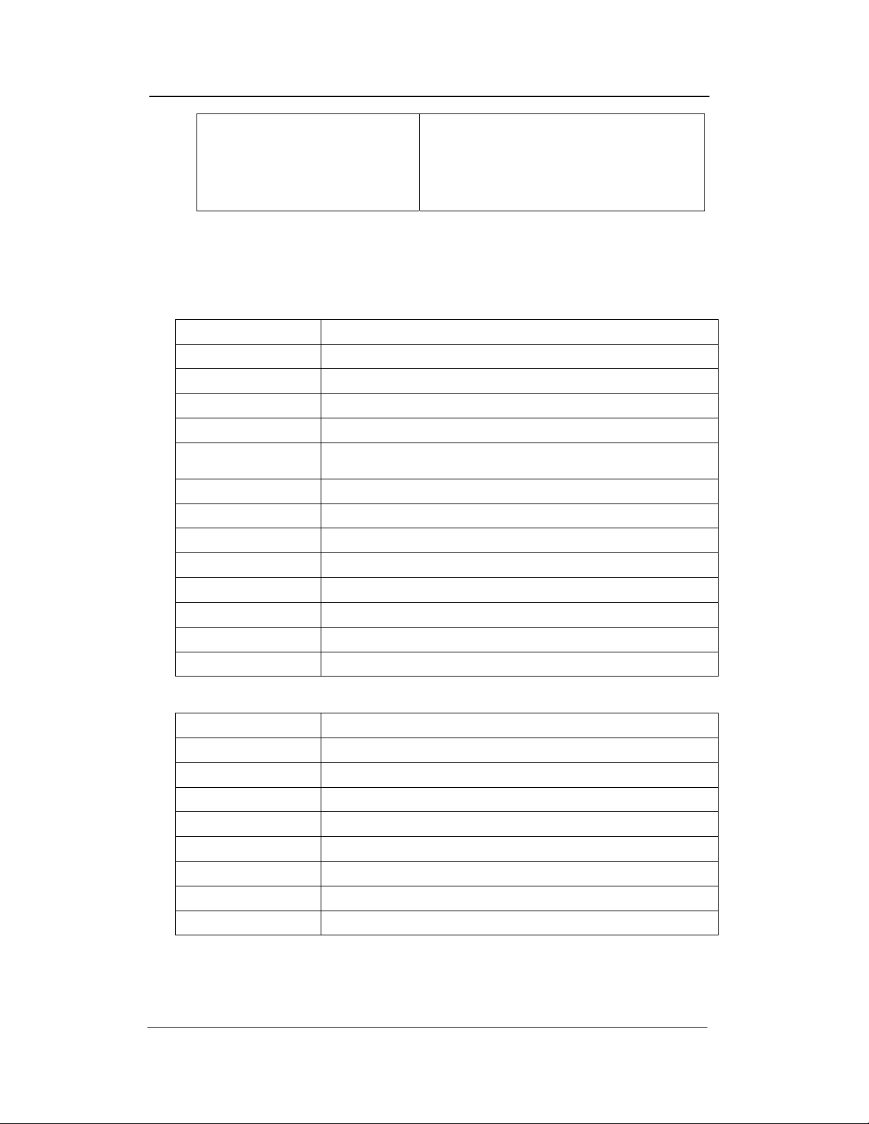
LED FUSE VOLTAGE DESCRIPTION
2 F2 -28.0 VDC Key phone and SLP operating Voltage
5 F4 +5.0 VDC Processor Voltage
3 F3 -70.0 VDC SLP Ring Supply
4 F5 -24.0 VDC External Battery Fuse
F1 -24.0 VDC Battery Output Fuse
1 ── ─── AC input
ATLAS EX 60 Installation - 28 -
Page 30

ATLAS EX 60 Installation
Backup Battery
The system power supply supports a backup battery package rated at 24 volts, 0.7amperes/hour. A
trickle-charge maintains the battery at 95% efficiency, applies system cutover to battery when facility
power is removed, and provides system shutdown when battery power falls below a specified level.
Attach batteries (24VDC) to the appropriate terminals. See Figure 19.
Keep the battery(s) dry and clean. Avoid damp wet areas or areas where the battery may be easily
damaged. Wires should run from the battery(s) to the terminals on the ATLAS EX 60 PSU (pay
particular attention to matching the positive connections).
Improper connection will damage the power supply. When operating from the battery, the system
will automatically cut off the power supply from the battery when the voltage gets too low, so that
the battery can be recharged.
LED5
J1
FG
CN3
T1
T2
SW2
CN4
F1
F2
F3
F5
F5
SW1
LED1
LED2
LED3
CN2
115V
K2 Relay
LED4
CN1
1
10
B-
J2
J3 B+
GND
-28V
-28V
-70V
NC
+5V
+5V
GND
GND
FGND
Figure 19 : ATLAS EX 60 System power supply
ATLAS EX 60 Installation - 29 -
Page 31

ATLAS EX 60 Installation
Switches/Connections
SW1 External Battery system boot switch
CN2 AC output on Transfermer
CN3 AC input
CN1 DC power cable**
CN4 AC input on Transfermer
J2 , J3 External Battery Connections
J1 Ground
SW2 AC Power switch interface (115 VAC or 230 VAC)
**Warning – This cable is polarity sensitive and MUST NOT be REVERSED!!
CAUTION!!! To reduce the risk of or injury please note the following:
Do not dispose of the battery (s) in a fire. The cell may explode. Check with local codes for special
disposal instructions.
Do not open or mutilate the battery(s). Released electrolyte is corrosive and may cause damage to the
eyes or skin. It may be toxic if swallowed.
Exercise care in handling the battery(s) in order not to short the battery with conducting materials
such as rings, bracelets and keys. The battery may overheat and cause burns.
Observe proper polarity orientation between the battery(s) and ATLAS EX 60 PSU.
Do not mix battery(s) of different sizes or from different manufacturers in this product.
The length of time system operation is maintained under battery power depends on battery capacity.
Typical system support for the 24 Volt battery(s) is approximately one hour.
MEMORY BACKUP SWITCH
♦ The memory backup switch (SW2) is located on the bottom left side of the MBU Card (See
Figure 1.)
Turning this switch ON will insure that the KSU will retain all stored programming in the event of a
power outage.
♦ ONCE THE SYSTEM IS INSTALLED, SET THE MEMORY BACKUP SWITCH TO
THE ON POSITION to prevent the loss of stored information.
♦ When the Memory Back-up switch is ON, the LED on the MBU Card (LED 1) will be lit.
ATLAS EX 60 Installation - 30 -
Page 32

ATLAS EX 60 Installation
Figure 1 : MBU Card...................................................................................................................................11
Figure 2 : Optional Equipment terminal PIN Functions.............................................................................12
Figure 3 : Serial Port Jack Pin Functions....................................................................................................13
Figure 4: SMDR Call Records and Explanations .......................................................................................14
Figure 5 : GROUNGING POST..................................................................................................................19
Figure 6 : HOW TO WALL MOUNTING..................................................................................................20
Figure 7 : Typical Trunk Connecting Jack Pin Functions...........................................................................21
Figure 8 : QUICK CONNECTOR ..............................................................................................................22
Figure 9 : Typical Station Connecting Jack Pin Functions.........................................................................22
Figure 10 : WALL MOUNT THE KEYPHONE ........................................................................................24
Figure 11 : ADJUST THE CLIP..................................................................................................................24
Figure 12: Single Line Telephone cable length...........................................................................................24
Figure 13: Digital Phone cable length.........................................................................................................25
Figure 14 : TKU...........................................................................................................................................26
Figure 15 : JUMPERS ON TKU .................................................................................................................26
Figure 16 : TDU...........................................................................................................................................27
Figure 17 : IIU .............................................................................................................................................27
Figure 18 : DSU/SLU ..................................................................................................................................28
Figure 19 : ATLAS EX 60 System power supply .......................................................................................29
ATLAS EX 60 Installation - 31 -
 Loading...