

Page 1
Eliza
56” CEILING FAN
READ AND SAVE THESE INSTRUCTIONS
FAN RATING AC 120V. 60Hz
QUICK ASSEMBLY NOTES:
* Do not wire in fan while house wires are Live. Turn power off at breaker before installation
begins.
* Do not use any controls, wall or remote, other than those provided by
* Please do not use any electric or battery powered tools in the assembly and installation of this
or any other Matthews Fan Company product.
* Fan should be assembled and mounted by two people.
Matthews Fan Company.
For Wet Location
Page 2

TABLE OF CONTENTS
Tools and Materials Required.........................................................................................
Package Contents .........................................................................................................
Safety Rules...................................................................................................................
Mounting Options...........................................................................................................
Attaching the Fan Blades...............................................................................................
Hanging the Fan ............................................................................................................
Make the Electric Connections.......................................................................................
Finishing the Installation.................................................................................................
Programming Your Fan and Operating the Remote Control and Wall Control............
Operating Your Fan .....................................................................................................
Care of Your Fan...........................................................................................................
Troubleshooting............................................................................................................
1
1
2
3
4
5
7
9
10
11
12
12
Page 3
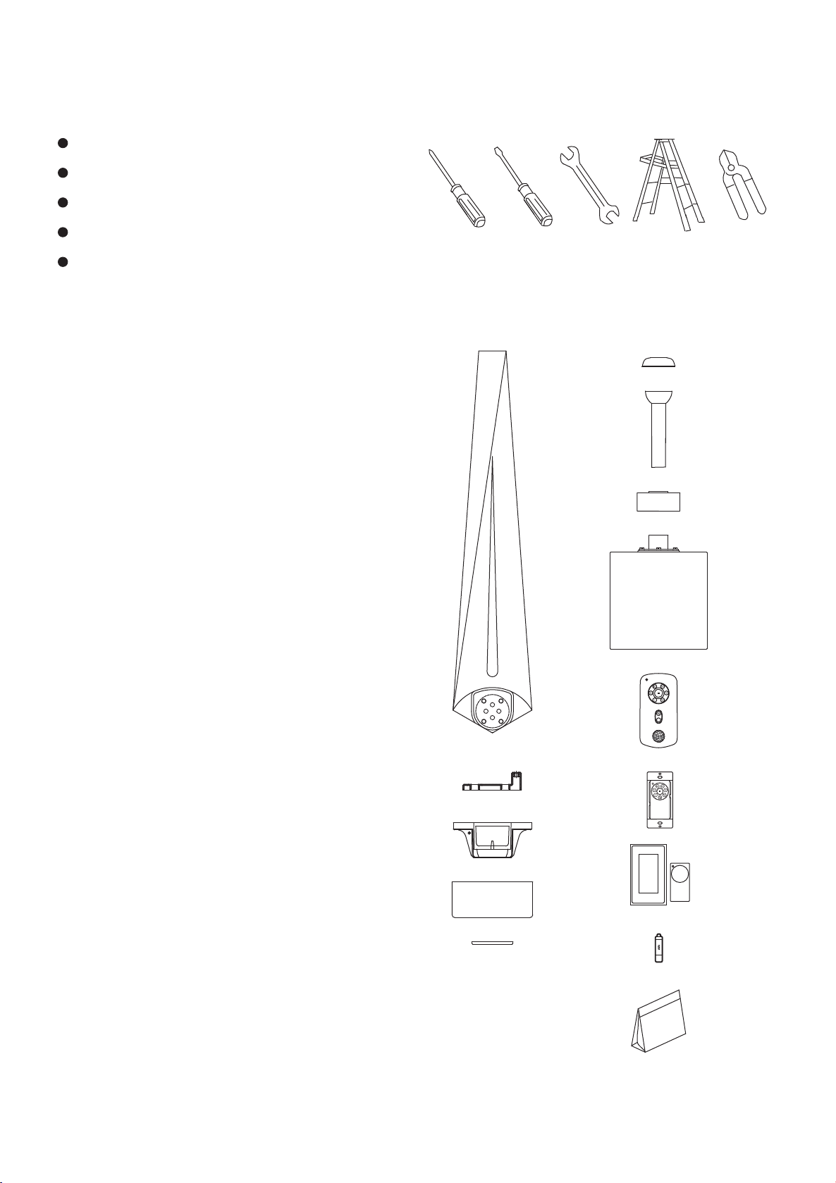
1. TOOLS AND MATERIALS
REQUIRED
Philips screwdriver
Blade screwdriver
11 mm wrench
Step ladder
Wire cutters
2. PACKAGE CONTENTS
Unpack your fan and check the contents. You should
have the following items:
f
a. Blade set (3)
b. Blade holders (3)
c. Hanger bracket
d. Canopy
e. Canopy bottom cover
f. Downrod Rubber Cover
g. Ball / down rod assembly
h. Coupling cover
i. Fan motor assembly
j. Hand held transmitter+holder+2 mounting screws
k. Wall transmitter incl. 2 mounting screws and 3
wire nuts
l. Wall plate incl. 1 face plate and 2 mounting screws
m. 12V batteries (2)
n. Package hardware
1) Mounting hardware:
wood screws (2), screws (2),
lock washers (2), washers (2),
star washers (2), wire nuts (3)
2) Blade holders attachment hardware:
screws+spring washers (10)
3) Blade attachment hardware:
screws (13), fiber washers (13)
Please do not use any electric or battery powered
tools in the assembly and installation of this or any
Matthews Fan Company product.
g
h
a
i
j
b
k
c
l
d
e
m
1
n
Page 4

3. SAFETY RULES
1. To reduce the risk of electric shock, insure
electricity has been turned off at the circuit
breaker or fuse box before beginning.
2. All wiring must be in accordance with the
National Electrical Code and local electrical
codes. Electrical installation should be
performed by a qualified licensed electrician.
3. WARNING: To reduce the risk of electrical
shock and fire, do not use this fan with any
solid-state fan speed control device.
4. WARNING: To Reduce The Risk Of Fire,
Electric Shock, Or Personal Injury, Mount To
Outlet Box Marked Acceptable for Fan
Support of 15.9 kg (35 lbs) or less And Use
Mounting Screws Provided With The Outlet
Box. Most outlet boxes commonly used for
the support of lighting fixtures are not
acceptable for fan support and may need to
be replaced, consult a qualified electrician if
in doubt.
5. The fan must be mounted with a minimum of
7 feet clearance from the trailing edge of the
blades to the floor.
6. To operate the reverse function on this fan,
press the reverse button while the fan is
running.
7. Avoid placing objects in the path of the
blades.
8. To avoid personal injury or damage to the fan
and other items, be cautious when working
around or cleaning the fan.
9. Do not use water or detergents when cleaning
the fan or fan blades. A dry dust cloth or lightly
dampened cloth will be suitable for most
cleaning.
10. After marking electrical connections, spliced
conductors should be turned upward and
pushed carefully up into outlet box. The
wires should be spread apart with the
grounded conductor and the equipment
-grounding conductor on one side of the
outlet box.
11. Electrical diagrams are reference only. Light
kit that are not packed with the fan must be
UL Listed and marked suitable for use with
the model fan you are installing. Switches
must be CUL General Use Switches. Refer
to the Instructions packaged with the light
kits and switches for proper assembly.
WARNING
TO REDUCE THE RISK OF PERSONAL
INJURY, DO NOT BEND THE BLADE
BRACKETS (ALSO REFERRED TO AS
FLANGES) DURING ASSEMBLY OR AFTER
INSTALLATION. DO NOT INSERT OBJECTS IN
THE PATH OF THE BLADES.
2
Page 5
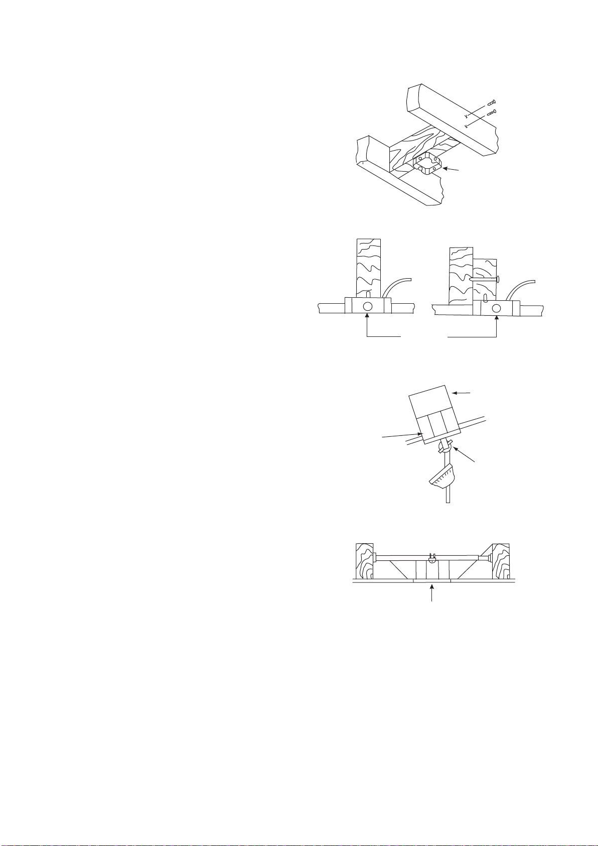
4. MOUNTING OPTIONS
If there isn't an existing UL listed mounting box,
then read the following instructions. Disconnect the
power by removing fuses or turning off circuit
breakers.
Secure the outlet box directly to the building
structure. Use appropriate fasteners and building
materials. The outlet box and its support must be
able to fully support the moving weight of the fan
15.9 kgs (35lbs) or less. Do not use plastic outlet
boxes.
Figures 1,2 and 3 are examples of different ways to
mount the outlet box.
Note: You may need a longer downrod to maintain
proper blade clearance when installing on a steep,
sloped ceiling. (Fig. 3)
To hang your fan where there is an existing fixture
but no ceiling joist, you may need an installation
hanger bar as shown in Figure 4.
Angled ceiling
maximum 25
Figure 1
Outlet box
Figure 2
º
Outlet box
Provide strong
support
Recessed
outlet box
Figure 3
Outlet box
Figure 4
Ceiling
mounting
bracket
3
Page 6

5. ATTACHING THE FAN
BLADES
Screws
Coupling cover
1. Remove the coupling cover and fan housing
from the fan motor by removing the two screws
from the rim of coupling cover. (Fig. 5)
2. Attach the blade holder to the blades using the
screws provided. Repeat process with other
blades. (Fig. 6)
3. Fasten the blade assembly to the fan motor
using the blade screws supplied. Repeat
process with other blades. Tighten each screw
and make sure the blade is straight. (Fig. 7)
Motor
housing
Collar
Fan motor
Figure 5
Screws
Blade holder
Blades
Fan
motor
Blade assembly
Figure 6
Screws
4
Figure 7
Page 7

6. HANGING THE FAN
Before touching a screw driver thoroughly
read these instructions.
Warning/Caution: Before installing fan, turn off
power at service panel and check all visible
screws and bolts for tightness.
1. Replace the coupling cover and fan housing
to the fan motor by using the screws previously removed (Fig. 8)
Screws
Coupling cover
Motor
housing
2. Remove the decorative canopy bottom cover
from the canopy by turning the cover counter
clockwise. (Fig. 9)
3. Remove the hanger bracket from the canopy
by removing the 1 of 2 screws from the
bottom of the hanger bracket and loosening
the other one a half turn from the screw
head. Next, turn the canopy counter clockwise to removing the hanger bracket from the
canopy. (Fig. 9)
4. Secure the hanger bracket to the ceiling outlet
box using screws and washers included with
your outlet box. (Fig. 10)
Fan motor
Figure 8
Ceiling
hanger
bracket
Ceiling
canopy
Canopy
cover
Figure 9
UL Listed
electrical
box
Hanger bracket
5
Tab
Mounting screws
(supplied with
electrical box)
Figure 10
Page 8

5. Loosen the two set screws and remove the
hitch pin and lock pin from the central
shaft/top coupling of the motor assembly.
Doing so will allow the down rod to enter the
central shaft. (Fig. 11)
6. Route wires exiting from the top of the fan
motor through the coupling cover, canopy
cover and canopy and then through the
ball/downrod. Place downrod rubber cover
onto the hanger ball (Fig. 11)
7. Align the holes at the bottom of the downrod
with the holes in the collar on top of the
motor housing. Carefully insert the hitch pin
through the holes in the collar and downrod.
Be careful not to jam the pin against the
wiring inside the downrod. Insert the lock pin
through the hole near the end of the hitch pin
until it snaps into its locked position. (Fig. 11)
Warning/Caution: Failure to properly install
lock pin as noted in step 7 could result in fan
loosening and possibly falling.
Supply wires
Downrod
Coupling
cover
Hitch pin
Downrod
rubber cover
Canopy
Canopy cover
Set screws
Lock pin
8. Tighten two set screws on top of the fan
motor firmly and slide the coupling cover
down.
9. Now lift the motor assembly (fan with blades)
into position and place the hanger ball into
the hanger bracket. Rotate down rod until the
"Check Tab" has dropped into the
"Registration Slot" and the down rod and ball
assembly seat firmly. The down rod and ball
assembly should not rotate if this is done
correctly. (Fig. 12)
10. An additional safety support is provided to
prevent the fan from falling. Secure the
safety cable to the ceiling joist with screw
and washer. (Fig. 12)
Figure 11
Screw
Safety cable
Registration
slot
Figure 12
6
Page 9

7. MAKE THE ELECTRIC
Outlet box
CONNECTIONS
NOTE: Your fan has included as standard
equipment two types of controls: a hand held
remote control and a wall mounted wall control.
You may use both as long as the dip switches
are calibrated the same. Select one of the
controls at this moment for installation and
programming of your fan.
Disconnect the power at the electrical box.
Follow the steps below to connect the fan to
your household wiring. Use the wire connecting
nuts supplied with your fan. Secure the
connectors with electrical tape. Make sure there
are no loose strands or connections.
A. Hand held remote control
1. Connect the fan supply (black) wire to the
black household supply wire as shown in Figure
13.
2. Connect the neutral fan (white) wire to the
white neutral household wire. (Fig. 13)
Black ("AC IN L")
Black (motor)
White ("AC IN N")
Green or bare
copper (ground)
Ground (green)
(Connect to ground wire
on hanger bracket if no
house ground wire exists.)
White (neutral)
Figure 13
3. Connect the fan ground wire (green) to the
household ground wire.
4. Check that the two plugs, large and small are
making proper contact. One plug is small with
only a single wire connection. The second plug
is larger and connects multiple colored wires.
5. After all splices are made, check to make
sure there are no loose strands. As an
additional precaution we suggest to secure the
plastic wire connectors to the wires with
electrical tape.
7
Page 10

B. Wall mount remote control
a. Fan wire connection
1. Connect the fan supply (black) wire to the black
household supply wire (Conductor cable between
ceiling and wall outlet box). (Fig. 14)
2. Connect the neutral fan (white) wire to the white
neutral household wire.
3. Connect the fan ground wire (green) to the
household ground wire.
4. Check that the two plugs, large and small are making
proper contact. One plug is small with only a single
wire connection. The second plug is larger and
connects multiple colored wires.
5. After all connections are made, check to make sure
there are no loose strands. As an additional precaution
we suggest to secure the plastic wire connectors to the
wires with electrical tape.
SUPPLY CIRCUIT
Ground
GREEN
WHITE WHITE
Conductor
Ceiling
Outlet Box
Ground to
Downrod
BLACK
BLACK
b. Installing the wall control
1. Remove the existing wall plate and the old switch
from the wall outlet box. Wire nut the BLACK leads
(hot) together and push back inside the outlet box.
2. Carefully tuck the wire connections inside the outlet
box. Secure the wall control with the two wall switch
screws provided. (Fig. 15)
3. Attach the wall plate over the wall control and secure
with the two wall plate screws provided.
Disclaimer: If a wall switch is to be used, for warranty to
be valid, our included wall control needs to be installed
to operate this fan.
Figure 14
Figure 15
8
Page 11

8. FINISHING THE
INSTALLATION
1. Tuck connections neatly into ceiling outlet
box.
2. Slide the canopy up to hanger bracket and
place the key hole on the canopy over the screw
on the hanger bracket, turn canopy until it locks
in place at the narrow section of the key holes.
(Fig. 16)
3. Align the circular hole on canopy with the
remaining hole on the hanger bracket, secure by
tightening the two set screws. Note: Adjust the
canopy screws as necessary until the canopy
and canopy cover are snug.
Warning: Make sure tab at bottom of hanger
bracket is properly seated in groove of hanger
ball before attaching canopy to bracket. Failure
to properly seat tab in groove could cause
damage to electrical wiring.
Outlet box
Hanger
bracket
Screws
Canopy
Canopy cover
Figure 16
9
Page 12

9. PROGRAMMING YOUR
FAN AND OPERATING
THE REMOTE CONTROL
AND WALL CONTROL
Before programming takes place, fan must be fully
assembled and mounted to the ceiling with blades
attached. You must also choose which control you
will be using for programming the fan, the remote
or the wall control. No other wall control should be
used with this fan but that which was included.
Using another wall control other than ours will
damage your fan and void your warranty.
Install one 23A/12V battery (included). To prevent
damage to transmitter, remove the battery if not used
for long periods of time (Fig. 16 & 17)
Restore power to ceiling fan and test for proper
operation.
A. I, II, III, IV, V and VI button:
These six buttons are used to set the fan speed as
follows:
I = minimum speed
II = low speed
III = medium low speed
IV = medium speed
V = medium high speed
VI = high speed
ON ECE
1234
Figure 16
B. button:
This button turns the fan off.
C. Reverse button:
This button is to control fan direction
D. SET code setting button:
Your DC brushless motor is equipped with automatically
learned type remote control and a wall control. If two
fans or more in a house, it is recommended that you not
use the factory code settings. Change codes setting to
any other combination of dip switch setting to avoid fan
interference issues, but users need to do control setting
process as below once the code setting is changed.
Please refer the "D" "SET" code setting button section.
Follow the below steps to set the remote control:
The auto learning function will only mandate within 60
seconds when turning the fan’s AC power ON.
a) Select desired frequency from the transmitter.
b) From the wall or remote transmitter, press the “SET”
button, and hold the “SET” button for over 10 seconds.
Once the receiver has detected the frequency, the light
will flash twice, and the fan will automatically begin to
operate and start to rotate in the counterclockwise
direction and on the highest RPM for 3 minutes. When
counter clockwise rotation has finished, the fan will
automatically reverse to clockwise direction again to the
highest RPM for 3 minutes. Fan will shut off when the
self calibration test has finished. The total self calibration
test will last about 6 minutes.
Figure 17
10
Figure 18
Page 13

NOTE: If the self calibration test failed, turn the AC
power off; restore power and process the self
calibration test again.
NOTE: During self calibration test, the remote and
the wall control are non-functional.
NOTE: The learning frequency function and self
calibration test will continue to retain the last set
frequency and calibration set even when the AC
power is shut off. If the frequency is changed the
self calibration test will occur again.
This receiver provides the following protective
function:
1. Lock Rotor Position: The DC motor has a built-in
safety against a stalled or locked rotor condition
(stalled blade rotation). If there is an obstruction or
fault with the motor, the current monitoring function
will automatically turn power off to the motor after 30
seconds. Remove the obstruction and turn the AC
power off. Restore power and re-start fan motor.
2. Over 80W protection: When the receiver detects
motor power consumption which is greater than
80W, the receiver power will be stopped and
operation will immediately discontinue. Wait for 5
seconds and then turn the receiver power back on.
10. OPERATING YOUR
FAN
Speed settings for warm or cool weather depend on
factors such as the room size. Ceiling height,
number of fans and so on.
NOTE:
press the reverse button while the fan is running.
Warm weather - (Forward) A downward airflow
creates a cooling effect as shown in Fig. 19. This
allows you to set your air conditioner on a warmer
setting without affecting your comfort.
Cool weather - (Reverse) An upward airflow moves
warm air off the ceiling area as shown in Fig. 20.
This allows you to set your heating unit on a cooler
setting without affecting your comfort.
To operate the reverse function on this fan,
Figure 19
Figure 20
11
Page 14

11. CARE OF YOUR FAN
Here are some suggestions to help you maintain your fan
1. Because of the fan's natural movement, some connections may become loose. Check the support
connections, brackets, and blade attachments twice a year. Make sure they are secure. (It is not
necessary to remove fan from ceiling.)
2. Clean your fan periodically to help maintain its new appearance over the years. Use only a soft brush or
lint-free cloth to avoid scratching the finish. The plating is sealed with a lacquer to minimize discoloration
or tarnishing. Do not use water when cleaning. This could damage the motor, or possibly cause an
electrical shock.
3. There is no need to oil your fan. The motor has permanently lubricated bearings.
IMPORTANT: MAKE SURE THE POWER IS OFF AT THE ELECTRICAL PANEL BOX BEFORE YOU
ATTEMPT ANY REPAIRS. REFER TO THE SECTION "MAKING ELECTRICAL CONNECTIONS".
12. TROUBLESHOOTING
Problem
Fan will not start.
Fan is noisy.
Remote control
malfunction.
Fan wobble.
Solution
1. Check circuit fuses or breakers.
2. Check line wire connections to the fan and switch wire connections in the switch housing.
CAUTION: Make sure main power is off.
3. Check that the battery of the remote is functional.
4. Check to make sure all receiver plugs are connected at top of motor.
5. Re-do steps for programming on page 8.
1. Make sure all motor housing screws are snug.
2. Make sure the screws that attach the fan blade bracket to the motor hub is tight.
3. Make sure wire nut connections are not rubbing against each other or the interior wall of the
switch housing. CAUTION: Make sure main power is off.
4. Allow a 24-hour "breaking-in" period. Most noise associated with a new fan disappear
during this time.
5. Some fan motors are sensitive to signals from solid-state variable speed controls. If you
have installed this type of control, choose and install another type of control.
6. Make sure the upper canopy is a short distance from the ceiling. It should not touch the
ceiling.
1. Do not connect the fan to a wall mounted variable speed control. Use our proprietary
provided wall control.
2. Make sure the dip switches are set correctly.
1. Check that all blade and blade arm screws are secure.
2. Most fan wobbling problems are caused when blade levels are unequal. Check this level by
selecting a point on the ceiling above the tip of one of the blades. Measure this distance.
Rotate the fan until the next blade is positioned for measurement. Repeat for each blade.
The distance deviation should be equal within 1/8".
3. If the blade wobble is still noticeable, interchanging two adjacent (side by side) blades can
redistribute the weight and possibly result in smoother operation.
WARNING: TO REDUCE THE RISK OF PERSONAL INJURY, DO NOT BEND THE BLADE ARM
WHILE INSTALLING, BALANCING THE BLADES, OR CLEANING THE FAN. DO NOT INSERT
FOREIGN OBJECTS BETWEEN ROTATING FAN BLADES.
Fan has jerky
movement
Fan has lost its
programming
repeatedly
1. Turn the AC power off to fan, and re-do steps for programming on page 10.
2. If fan still has jerky movement, verify that both motor wire plugs are properly connected.
1. Turn the AC power off to fan, and re-do steps for programming on page 10.
2. Do not turn off fan from wall switch. Use only remote to regulate fan.
12
Page 15

INSTRUCTIONS ON HOW TO PROGRAM MULTIPLE FANS ON SINGLE
CIRCUIT BREAKER.
1. Turn the power off at the breaker/service box.
2. Hang all fans by convenience cable located in top of motor to hook in ceiling bracket. This will allow
you to easily access the leads from house and the leads of the fan. Do not connect house and fan
leads, yet.
3. Make house lead connections to those of first fan, but do not install blades or motor cover.
4. Turn the breaker on.
5. Hold down the “set” button in battery compartment of one of the remote controls in close proximity to
fan to be programmed first.
6. Let the first fan fully program. It will run forward and backward for about 5 minutes.
7. Once first fan is fully programmed, turn the power off from the breaker and disconnect the leads from
the house to the fan just programmed.
8. Make house lead connections to second fan, but do not install blades or motor cover.
9. Change the dip switch positions on the second remote to a different position/frequency than those of
the first fan’s remote.
10. Repeat steps 4 to 6.
11. Now, fully reconnect the leads of the first fan and fully install the blades and motor covers on both
fans. Turn the breaker back on.
12. All your fans should now be installed and programmed to different remotes on the same circuit
breaker.
13. Finally, with each remote and for each fan, hold down the “VI” button and let the fans program
themselves again, but to the weight of the blades.
Please Call Matthews Fan Company for questions: 847-680-9043
13
Page 16

LIMITED LIFETIME WARRANTY
MATTHEWS-GERBAR, LTD. DBA MATTHEWS FAN COMPANY LIFETIME LIMITED WARRANTY.
Ceiling fans are warranted by Matthews-Gerbar, Ltd. to the original user against defects in workmanship or
materials under normal use and inside installation for: Motors: Lifetime of original purchaser: Labor &
Component parts: (lights, finish, blades, etc…): one year after date of purchase, Light Bulbs: no warranty.
Any part, which is determined by Matthews-Gerbar, Ltd. to be defective in material or workmanship and
returned to an authorized service location, as Matthews-Gerbar, Ltd. designates, shipping costs prepaid, will
be, as the exclusive remedy, repaired or replaced at Matthews-Gerbar Ltd.'s option providing that proof of
purchase is provided. For limited warranty claim procedures, see PROMPT DISPOSITION below. This
limited warranty gives purchasers specific legal rights, which may vary from state to state.
LIMITATION OF LIABILITY. To the extent allowable under law, Matthews-Gerbar, Ltd.'s liability for
consequential and incidental damages is expressly disclaimed. Matthews-Gerbar, Ltd.'s liability in all events
is limited to, and shall not exceed, the purchase price paid.
WARRANTY DISCLAIMER. Matthews-Gerbar, Ltd. has made a diligent effort to illustrate and describe the
products in this literature accurately: however, such illustrations and descriptions are for the sole purpose of
identification, and do not express or imply that the products will necessarily conform to the illustrations or
descriptions. Furthermore, there is no express warranty derived from any viewed sample or model.
Matthews-Gerbar, Ltd. disclaims any expressed warranty and implied warranty of merchantability
and fitness for a particular use.
Except as provided below, no warranty or affirmation of fact, expressed or implied, other than as stated in
"Limited Lifetime Warranty" above is made or authorized by Matthews-Gerbar, Ltd.
PRODUCT SUITABILITY. Many states and localities have codes and regulations governing sales,
construction, installation and/or use of products for certain purposes, which may vary from those in
neighboring areas. While Matthews-Gerbar, Ltd. attempts to assure that its products comply with such
codes, it cannot guarantee compliance and cannot be responsible for how the product is installed or used.
Before purchase and use of a product, please review the product application and national and local codes
and regulations, and be sure that the product, installation, and use will comply with them.
Matthews-Gerbar, Ltd. disclaims any expressed warranty and implied warranty of merchantability
and fitness for a particular use if any modifications are made to the original manufacturer's product.
Certain aspects of disclaimers are not applicable to consumer products: e.g.(a) some states do not allow the
exclusion or limitation of incidental or consequential damages, so the above limitation or exclusion may not
apply to you: (b) also, some states do not allow limitations on how long an implied warranty lasts,
consequently the above limitation may not apply to you.
OTHER EXCLUSIONS. This warranty does not cover defects caused by: exposure to extremes of heat and
humidity, neglect, modification, alteration, repair or service of the enclosed product by anyone other than an
authorized Matthews-Gerbar, Ltd. service center; physical abuse to, or misuse of, the product or operation of
it in a manner contrary to the accompanying instructions; or shipment of the product to a Matthews-Gerbar,
Ltd. dealer or service center for service. This warranty also excludes all costs arising from adjustment of
user controls, products purchased outside of the U.S.A., and costs for initial technical adjustments (set-up).
Matthews-Gerbar assumes no liability for labor costs, installation costs or other losses. Consult the operating
instructions included with the product for information regarding user controls.
PROMPT DISPOSITION. Matthews-Gerbar, Ltd. will make a good faith effort for prompt correction respect
to any product, which proves to be defective within limited lifetime warranty. For any product believed to be
defective within limited lifetime warranty, first call or write dealer from whom the product was purchased.
Dealer will give additional directions. If unable to resolve satisfactorily, call Matthews-Gerbar, Ltd. at the
phone number below, giving the dealer's name, address, date and number of dealer's invoice, and describe
the nature of the defect. Title and risk of loss pass to buyer on delivery to common carrier. If product was
damaged in transit to you, file claim with the carrier.
MATTHEWS-GERBAR, LTD.
1881 Industrial Drive - Libertyville, IL - 60048
Tel (847) 680-9043 - Fax (847) 680-8140
 Loading...