

Atlas CP400 Owner's Manual
CP400 & CP700
PROTECT
LIMIT
SIGNAL
CH-1
PROTECT
POWER
LIMIT
SIGNAL
CH-2
CP700
Commercial Power Amplifier
Commercial Power Amplifier
Owner’s Manual
CP400 & CP700
Commercial Power Amplifiers
1601 Jack McKay Blvd. • Ennis, Texas 75119 U.S.A.
Telephone: 800.876.3333 • Fax: 800.765.3435
AtlasSound.com – 1 –
Specifications are subject to change without notice.
CP400 & CP700
Commercial Power Amplifier
Owner’s Manual
TABLE OF CONTENTS
Introduction ..........................................................................................................3
Features ...............................................................................................................3
Applications ..........................................................................................................3
Front Panel Description ........................................................................................4
Rear Panel Description .........................................................................................5
Input Wiring ..........................................................................................................7
Speaker Output Wiring .........................................................................................9
Specifications .......................................................................................................15
Warranty ...............................................................................................................16
SAFETY INSTRUCTIONS
Please Read Carefully Before Installing or Operating This Product
• Read instructions fully.
• Pay attention to any and all warnings.
• Connect this amplier only to the correct operating voltage.
• Do not attempt to service this unit. Only a qualied service technician should open this unit for
servicing.
• Warning: To reduce the risk of re or electric shock, do not expose this appliance to rain or
moisture.
HEARING DAMAGE!
All professional loudspeaker systems are easily capable of producing very high sound pressure
levels. Use care with the operation of this amplier and wear the appropriate hearing protection.
Exposure to excessive sound pressure levels can cause permanent hearing damage.
SHOCK HAZARD!
The Atlas Sound CP400 and CP700, when in operation, can produce a shock hazard at the speaker
terminals. Make sure the amplier is turned off when installing or removing connections at the
speaker terminal barrier strip. After connecting the proper speaker load, REPLACE the terminal
strip cover!
VENTILATION
Although the CP400 and CP700 are internally fan cooled and have thermal protection circuitry,
adequate ventilation is required to ensure trouble-free operation. When rack mounting one or
more of the Atlas Sound CP Series power ampliers, install an exhaust fan in the rack to evacuate
heat buildup. Consult Atlas Sound’s Technical Support at 1-800-876-3333 for advice on thermal
management and assistance with rack selection for this product.
RACK MOUNTING
Although the internal output transformers are mounted close to the front panel, when rack
mounting the CP400 and CP700, be sure the unit has adequate front and rear support.
1601 Jack McKay Blvd. • Ennis, Texas 75119 U.S.A.
Telephone: 800.876.3333 • Fax: 800.765.3435
AtlasSound.com – 2 –
Specifications are subject to change without notice.

CP400 & CP700
Commercial Power Amplifier
Owner’s Manual
INTRODUCTION
Congratulations and thank you for purchasing the Atlas Sound CP400/CP700 dual channel power
amplier. This product is a professional grade audio power amplier specically designed for
demanding contractor applications and engineered to provide years of faithful service. Two
independent channels driven by separate power supplies ensure maximum channel separation and
ultra low distortion gures. Whether your application is a large distributed constant voltage sound
system or a high SPL sound reinforcement system, the Atlas Sound Series is the answer for high
power/low cost amplication needs.
FEATURES
• Independent power supplies
• Soft clip limiter protection
• Dual-speed, high efciency fan cooling
• Stepped attenuators mounted on the rear for security
• Stereo, bridge, or parallel operating modes selectable via rear mounted switch
• Balanced inputs on barrier strip and XLR connectors
• Loop through feature on male XLRs, one per channel input
• Short-circuit, temperature, and DC offset protection
• 25V, 70.7V, 100V, and direct coupled (2,4, and 8 Ω) outputs mounted on barrier strips with covers
for safety
• Toroidal output transformers provide extended high frequency response and effectively lower the
electrical interference
• Power-up muting
APPLICATIONS
The Atlas CP400/CP700 are the perfect choice for distributed paging/BGM systems, foreground
music systems, and distributed sound masking applications. They are also at home in night clubs,
theaters, portable sound systems, and anywhere clean high-delity audio amplication is needed.
1601 Jack McKay Blvd. • Ennis, Texas 75119 U.S.A.
Telephone: 800.876.3333 • Fax: 800.765.3435
AtlasSound.com – 3 –
Specifications are subject to change without notice.
CP400 & CP700
PROTECT
LIMIT
SIGNAL
CH-1
PROTECT
POWER
LIMIT
SIGNAL
CH-2
CP700
Commercial Power Amplifier
Commercial Power Amplifier
Owner’s Manual
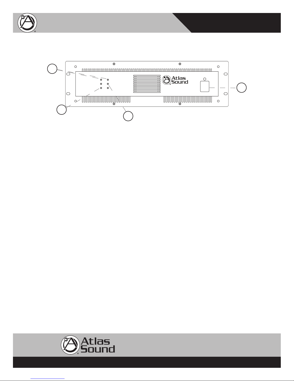
FRONT PANEL DESCRIPTION
2
1
Figure 1
1. Power Switch
This rocker switch supplies power to the amplier. A red LED located above the power
switch will illuminate when the amplier is switched on.
2. Protect LED Indicators
The amplier features several types of protection circuitry to prevent damage during
power-up or fault conditions. If any of these LEDs illuminate, one of the various protection
features is safeguarding the amplier. The output relays will disconnect the speaker loads when
the protection circuitry detects a fault condition.
• Loudspeaker Protection - When power is rst applied, the speaker protection relay is
open, preventing transients from reaching the loudspeakers. After the internal power
supplies have stabilized, the relay will close, connecting the amplier output to the load.
The yellow Protect LEDs will illuminate during this power-up process.
• Thermal Protection - The amplier protection circuitry monitors itself for excessive
internal operating temperatures. In the event this circuitry detects abnormal thermal
conditions (blocked cooling fan or high ambient temperatures), the speaker relay
will disconnect the speaker load from the amplier. Once the internal operating
temperature drops back to a safe level, the relay will close, reconnecting the speaker load
to the amplier.
• Short Circuit Protection - The yellow Protect LEDs will illuminate should the amplier
detect a short circuit on the attached speaker load or if the load impedance is too low.
When this condition is detected, the internal speaker relays will open up, disconnecting
the load from the amplier. The protection circuitry will stay activated until the fault is
cleared.
Note: Once the specic fault has been corrected, the power may have to be cycled to reset the
protection circuitry.
3. Signal “Status” LED Indicator
The green “Status” LEDs will illuminate once the input signal has reached -26 dBV or higher.
3
4
1601 Jack McKay Blvd. • Ennis, Texas 75119 U.S.A.
Telephone: 800.876.3333 • Fax: 800.765.3435
AtlasSound.com – 4 –
Specifications are subject to change without notice.
CP400 & CP700
++--GND
CH-2 CH-1
AMPLIFIER INPUTS
THRU
IN
THRU
IN
CAUTION
AC100V-50/60Hz
AC120V-50/60Hz
AC230V-50/60Hz
AC240V-50/60Hz
TO REDUCE THE RISK OF ELECTRIC SHOCK
DO NOT REMOVE COVER (OR BACK)
NO USER SERVICEABLE P AR TS INSIDE
REFER SERVICING TO QUALIFIED SERVICE PERSONNEL
POWER
CP700
Commercial
Power
Amplifier
Per Channel
Output Power
400 W / 4 Ohms
350 W / 70.7 V
PROTECT
LIMIT
SIGNAL
CH-1
PROTECT
POWER
LIMIT
SIGNAL
CH-2
CP700
Commercial Power Amplifier
LEVEL
-
0
0
5
6
4
0
3
2
2
6
2
2
1
8
1
6
1
4
1
2
1
0
8
6
4
2
0
LEVEL
-
0
0
5
6
4
0
3
2
2
6
2
2
1
8
1
6
1
4
1
2
1
0
8
6
4
2
0
1601 Jack McKay Blvd., Ennis, TX 75119
(800) 876-3333 AtlasSound.com
STEREO
PA RALLELBRIDGE
GND
CH-1 CH-1
- 100V +
-+
70V
-+
25V
8, 4, and 2 Ohms
AUDIO TRANSFORMER
DIR. OUTPUT ISOL. OUTPUT
-+70 1000
BRIDGE
MONO
+
CH-2 CH-2
- 100V +
-+
70V
-+
25V
8, 4, and 2 Ohms
AUDIO TRANSFORMER
DIR. OUTPUT ISOL. OUTPUT
-+70 1000
BRIDGE
MONO
-
AVIS RISQUE DE CHOC ELECTRIQUE
NE PAS OUVRIR
CAUTION
RISK OF ELECTRIC SHOCK
DO NOT OPEN
MA D E I N C H I N A
Commercial Power Amplifier
Owner’s Manual
4. Limit LED Indicator
The CP400 and CP700 come equipped with limiter circuitry and LEDs to indicate when this
circuitry is activated. The limiter circuitry engages only when the input signals reach a specic,
factory set magnitude. Once this limit has been reached, the circuitry will reduce the input level
enough to prevent clipping at the speaker output terminals.
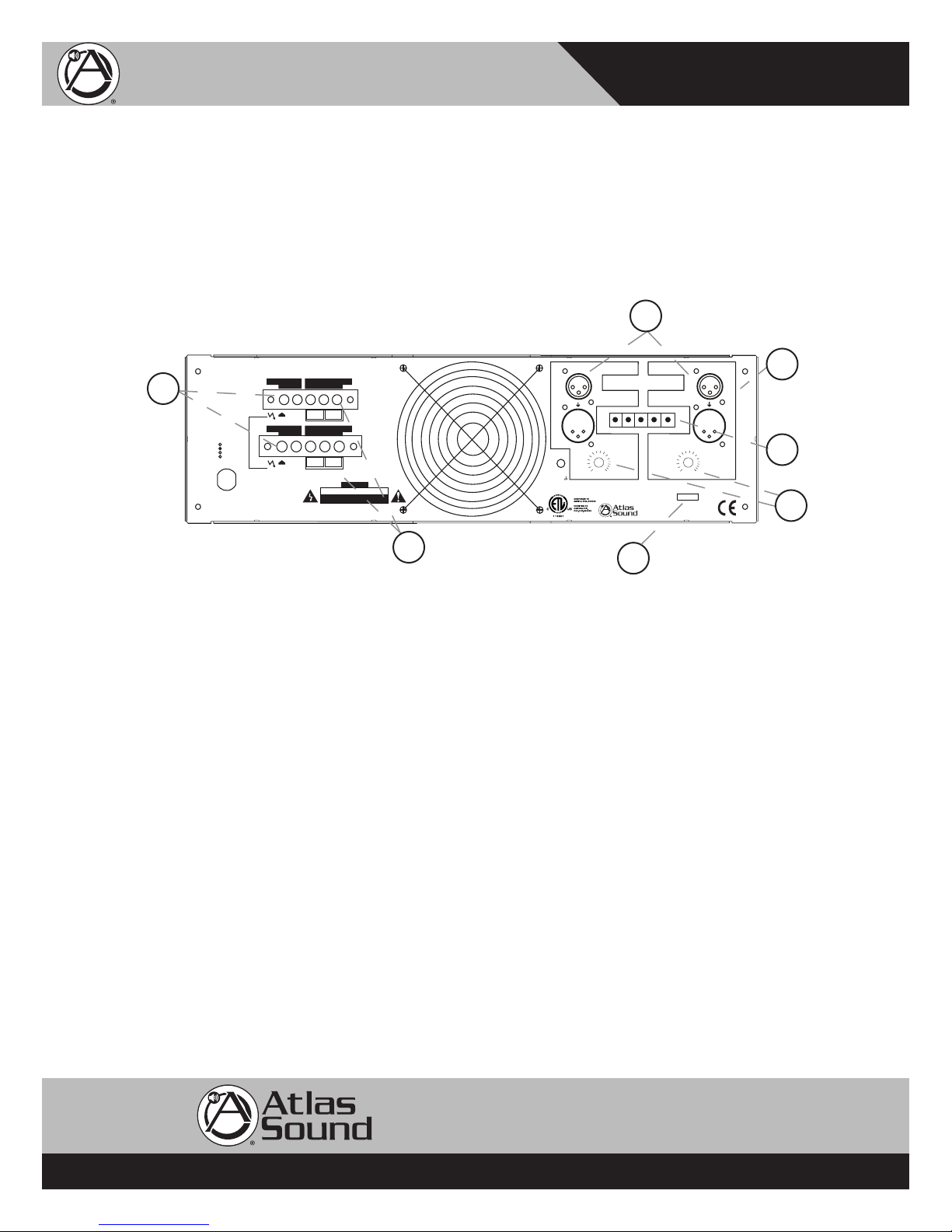
REAR PANEL DESCRIPTION
10
11
6
8
7
5
9
Figure 2
5. Gain Controls
One stepped attenuator per channel increases or decreases the sensitivity by 2 dB per step.
Maximum voltage gain is 32 dB.
6. CH1/CH2 Inputs (XLR Connectors)
Two female XLR inputs (one per channel) are provided. These inputs are balanced and
congured as follows: pin 1 ground, pin 2 +, pin 3 -. The XLR connections are typically used in
portable audio systems where quick connect and disconnect is warranted.
7. Balanced Barrier Strip Inputs
Balanced inputs are provided on this barrier strip for permanent installation applications. The
use of the appropriate spade type lug is highly recommended for best connection integrity and a
neat, professional appearance.
8. CH1/CH2 Loop Through
Two male XLR (one per channel) are provided for looping the input signals to other devices.
These connectors are wired in parallel with the female XLR inputs, pin for pin.
AtlasSound.com – 5 –
1601 Jack McKay Blvd. • Ennis, Texas 75119 U.S.A.
Telephone: 800.876.3333 • Fax: 800.765.3435
Specifications are subject to change without notice.
 Loading...