

Page 1

CONTENTS
Product Features and Specifications ..............................................1
Installation Requirement ............................................................ 3
Steps of Installation ………………………………………………..……………………………4
Exploded View ..........................................................................21
Test Run ..................................................................................24
Operation Instruction ................................................................25
Maintenance ........................................................................... 26
Trouble Shooting ..................................................................... 27
Parts List................................................................................. 28
Page 2
I. PRODUCT FEATURES AND SPECIFICATIONS
FLOOR PLATE CHAIN-ASSIST MODEL FEATURES
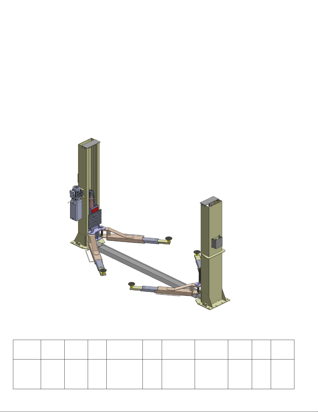
Model BP12000 (See Fig. 1)
·Dual hydraulic chain-assist cylinders, designed and made on ANSI standards, utilizing NOK oil
seal in the cylinders
· Self- lubricating UHMW Polyethylene sliders and bronze bushings
· Single point safety release and dual safety design
· Symmetric arms design with 3-stages on the front and rear arms
· Convenient width adjustment: Distance between columns 3137mm (123 1/2”) and 3000mm
(118 1/8”)
. Stackable rubber pads with 1.5, 3 and 6” inch extension adaptors
MODEL BP12000 SPECIFICATIONS
Model Style
BP
12000
Base Plate
Chain-Drive
Lifting
Capacity
12,000lbs
Lifting
Time
55
Seconds
73 1/4” – 83 7/8”
Lifting Height
1860mm -
2130mm
Overall
Height
3110mm
122 1/2”
Fig. 1
Overall Width
3692/3829mm
145 3/8”-150
1
3/4”
Width
Between
Columns
3000/3137mm
118 1/8”-123
1/2”
Minimum
Pad
Height
115 mm
4 1/2”
Gross
Weight
980Kg
2,156lbs
Motor
4.0 HP
Page 3
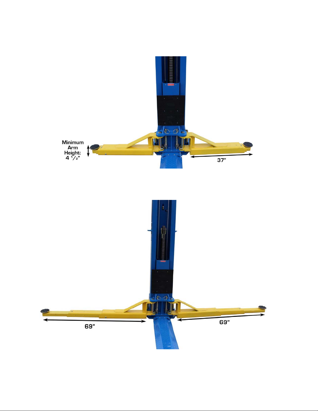
Arm Dimensions
For Model 212
Fig. 2
2
Page 4
II. INSTALLATION REQUIREMENTS
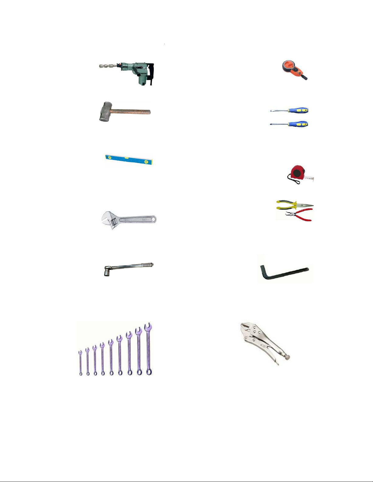
A. TOOLS REQUIRED
9 Rotary Hammer Drill (3/4” Bit)
9 Hammer
9 4 Foot Level Bar
9 Crescent Wrench (12inch)
9 Carpenter’s Chalk
9 Screw Driver Sets
9 Tape Measure (25’)
9 Pliers
9
Ratchet Spanner With Socket (28
mm
)
3
Wrench set (mm)
(10#, 13#, 14#, 15#, 17#, 19#, 24#, 27#)
9 Allen Head Wrench (6
3 Vise Grips
#
)
Fig. 3
3
Page 5
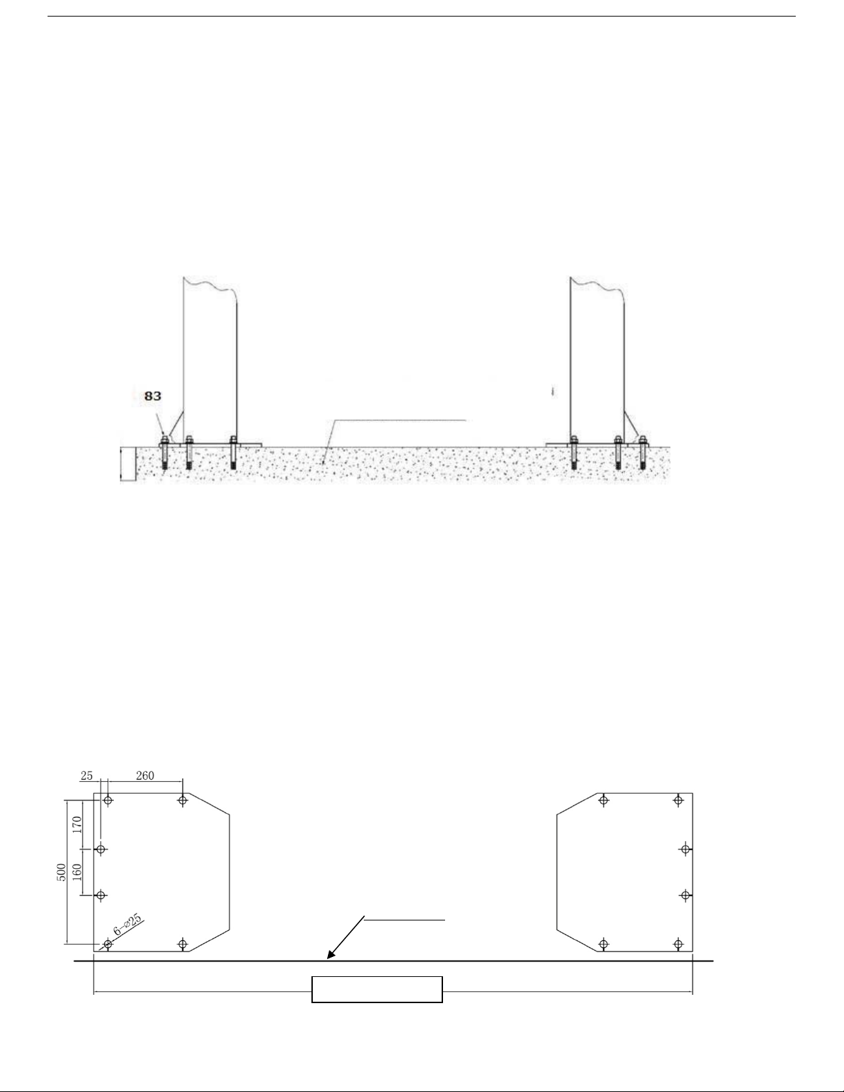
B. CONCRETE SPECIFICATIONS (See Fig. 4).
Concrete specifications must be adhered to.
Failure to do so may result in personal injury; lift and/or vehicle falling.
1. Concrete must have a minimum thickness of 6 inches. Concrete must be cured before the
installation.
2. Concrete must be in good condition and must be of test strength 3,000psi (250kg/cm²)
minimum.
3. Floors must be level and no cracks.
83
Concrete strength 3,000psi
6” 6”
Fig. 4
C. POWER SUPPLY
The power unit source must be 3Kw minimum. The electrical wire size must be a minimum of 10
gauge with a sufficient ground source. Minimum of a 30 amp breaker is required.
III.STEPS OF INSTALLATION
A. Location of Installation
Make sure the location of the lift (concrete, layout, space size etc.) is suitable for installation.
B. Use a carpenter’s chalk line to establish installation layout of the base plate
(See Fig. 5).
Snap a line
1453/8” or 1503/4”
Fig. 5
4
Page 6
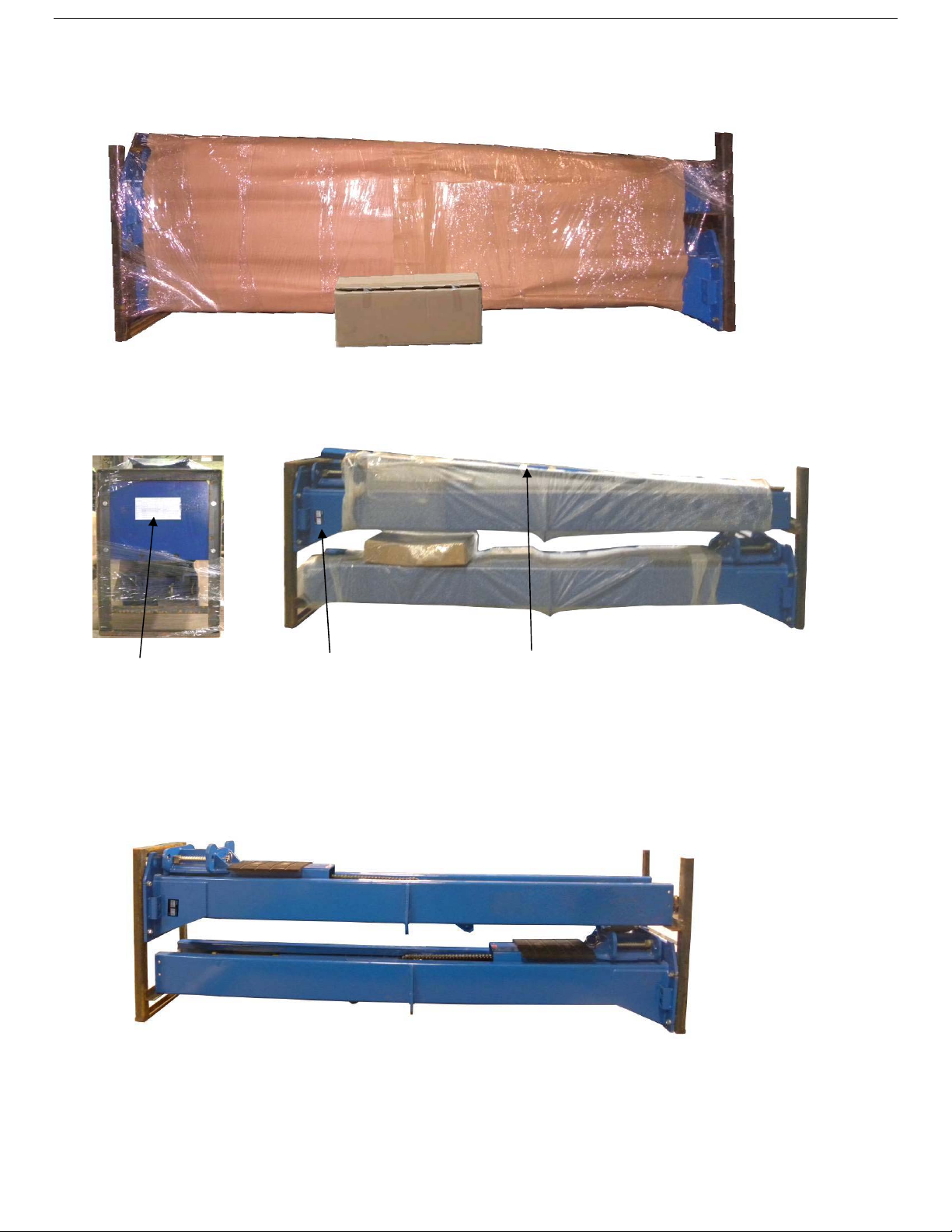
C. Check the parts before assembly.
1. Packaged lift and hydraulic power unit (
See Fig. 6).
Fig. 6
2. Move the lift aside with fork lift or hoist, and open the outer packing carefully
(See Fig. 7).
Shipment Parts list
Fig. 7
Floor cover Serial #
3. Remove the parts from the upper and inside of the column. Remove the parts box, and check the
parts according to the shipment parts list
(See Fig. 8).
Fig. 8
4. Loosen the bolts on the upper package stand, take off the upper column and remove the
package stand
.
5
Page 7
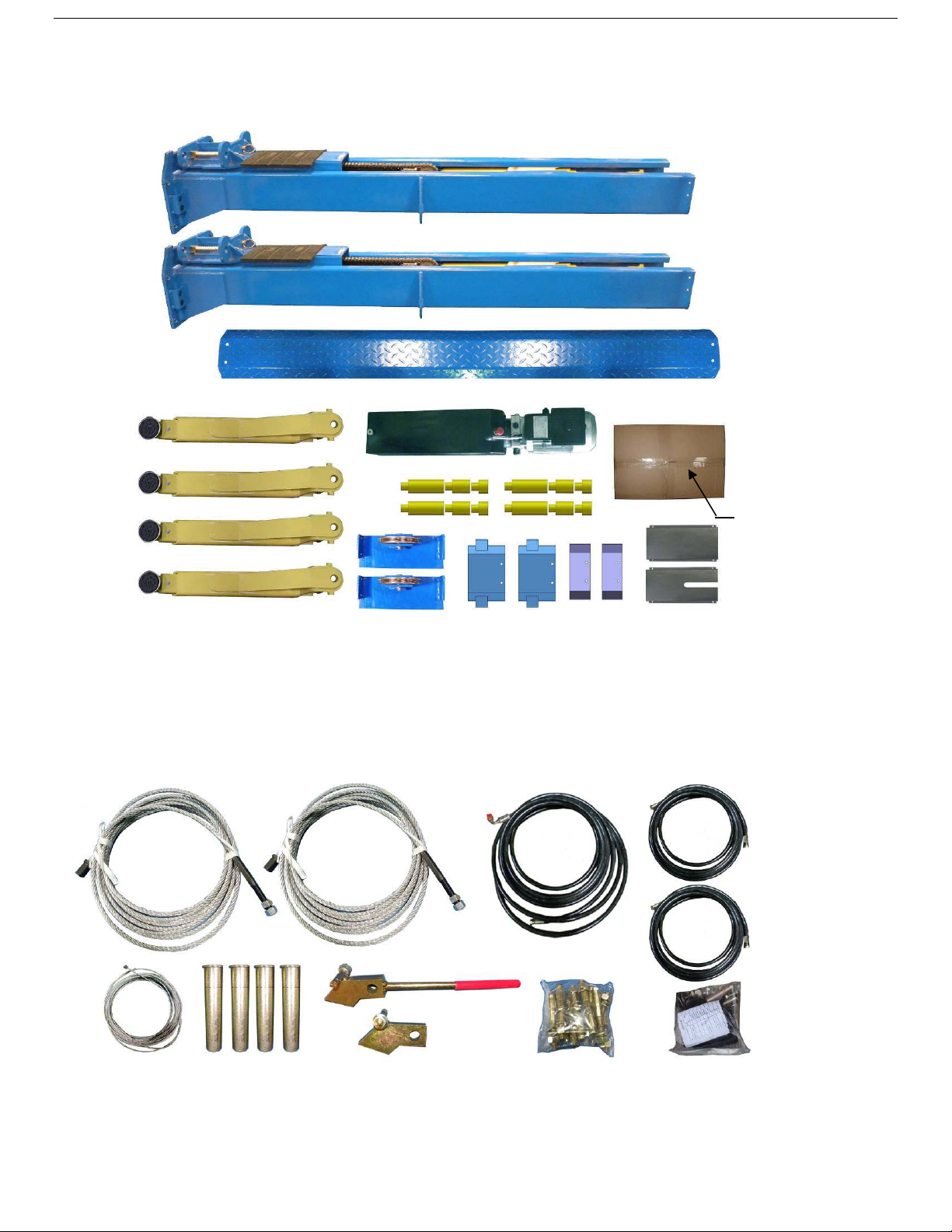
5. Move aside the parts and check the parts according to the shipment parts list
(See Fig. 9).
Fig. 9
6. Open the parts box (84) and check the parts according to parts box list
(See Fig. 10).
Fig. 10
6
Page 8
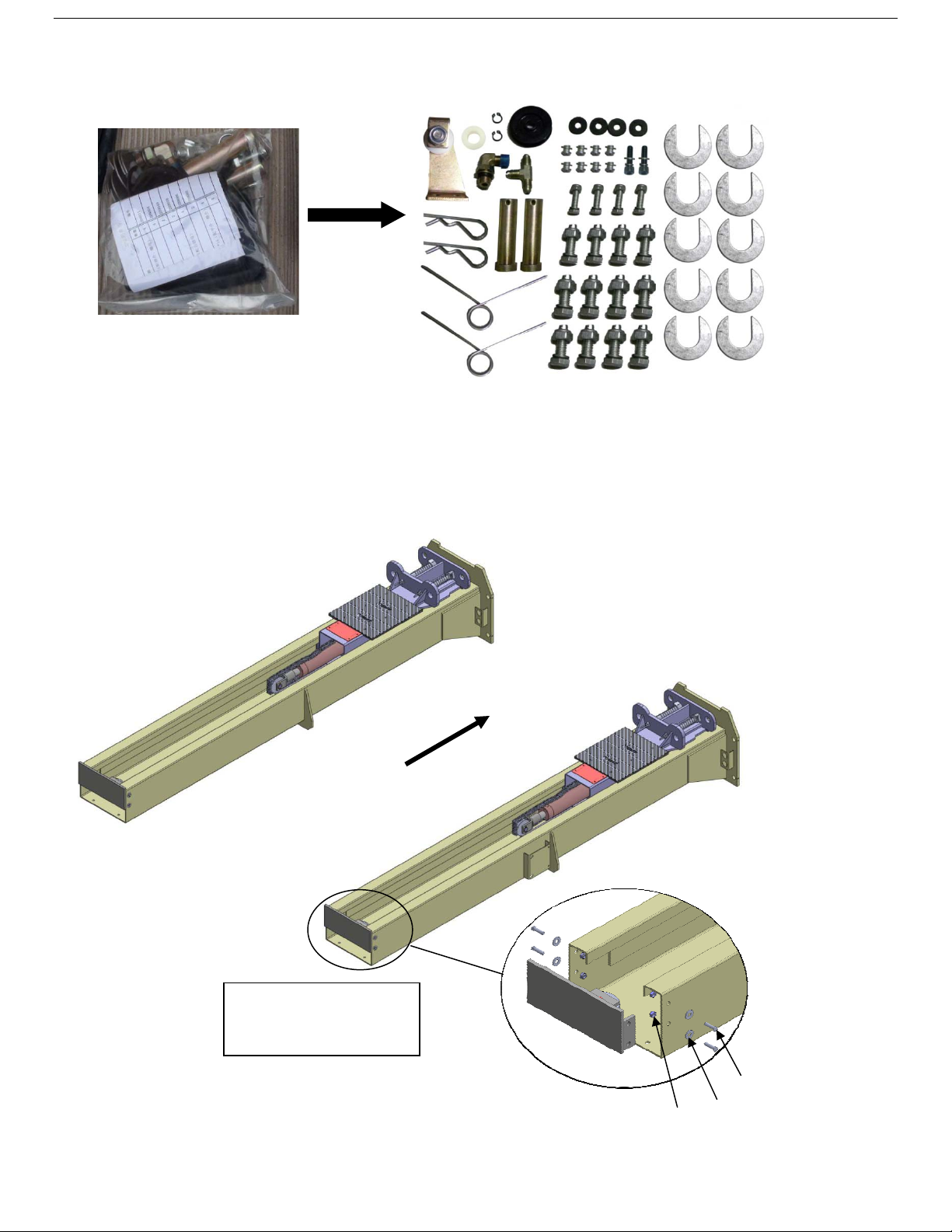
7. Check the parts in the parts bag according to parts bag list (See Fig. 11).
Fig. 11
D. Position power side columns
Lay down two columns on the installation site parallel, position the power side column according
to the actual installation site. Usually, it is suggested to install power side column on the right
side. Install the top plates
Offside column
(See Fig.12).
Power side column
Car-in direction
Assemble top plates using
M12*30 hex bolt with nut
and washer.
Fig. 12
51
52
53
7
Page 9
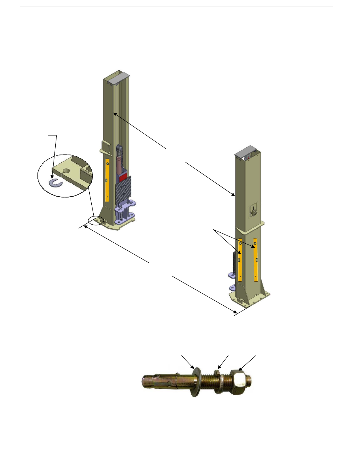
E. Position the columns check the columns for plumb with a level bar, and adjust with the
shims if the columns are not true.
(See Fig. 13).
Note: Set the width to 145 3/8” or 150 ¾”
Adjust the columns
to vertical with the
shims
54
118 1/8” or 123 1/2”
F. Fix anchor bolts
1. Prepare anchor bolts
145 3/8 or 150 3/4
(See Fig. 14).
check the columns
plumb (front and side)
with level bar
Fig. 13
Lock washer Washer Nut
Fig. 14
8
Page 10
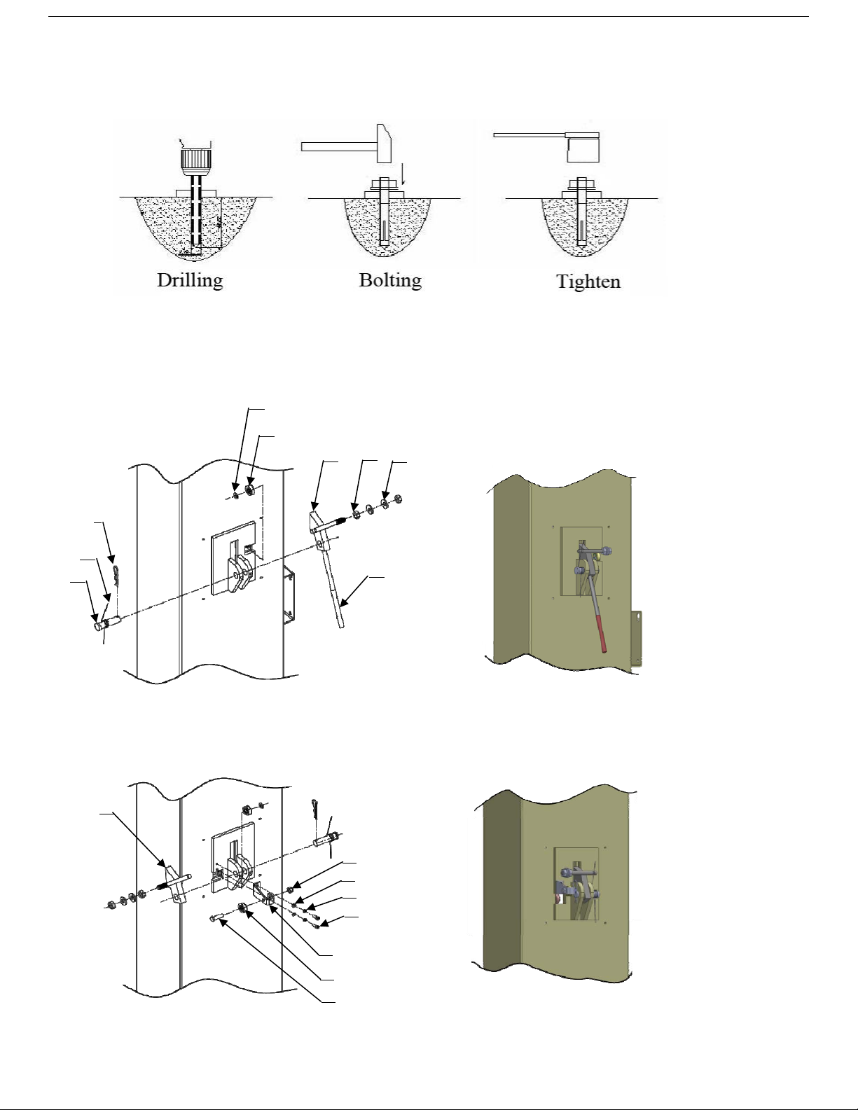
2. Use a rotary hammer drill and ¾” masonry bit. Drill all the anchor holes and install the anchor
bolts. Tighten the anchor bolts between 60 and 86 foot pounds.
Fig. 15
G. Install safety locks
(See Fig. 16&17).
57
58
60
59
52
(See Fig. 15).
55
6
56
61
Power side safety lock
Fig. 16
62
63
64
65
66
67
68
69
Offside safety lock
Fig. 17
9
Page 11

H. Lift the carriages up by hand and lock them at the same level
(See Fig. 18).
Safety device locked at the
same level
Fig. 18
10
Page 12

I. Install cable
According to step E (Width Setting) to choose the width distance of your lift
Note: Follow cable routing diagram below
1. For width distance with 150 3/4”
(See Fig.19).
70
(See Fig.13).
70
Upper cable plate
Pass the cable through from the
bottom to the top of the two
plates on the carriages.
Fig. 19
11
Page 13

2. For width distance with 145 3/8”
g
2.1. Pass through the cable from the bottom to the top of the carriage, The fitting of cable pass
through the hole of the carriages and be screwed with two cable nuts.
71
Threaded with
two cable nuts
Cable connect
plate
(See Fig. 20).
Cable pass
h direction
thou
Pass the cable through the
hole on the two cable
connecting plates on the
carriages.
Cable pass though
direction
Fig. 20
12
Page 14

2.2. Pass the cable through as shown below(See Fig. 21).
70
70
Fig. 21
13
Page 15

J. Install the cable on the safety locks
(See Fig. 22).
Note: Install the safety cable from the offside safety first. Pay attention to the pass through
direction.
1. Install the safety
cable from the
offside safety lock
2. According to the arrow
direction, pass the cable
from offside safety lock to
the power side safety lock
63
72
3. Reinstall the nuts
after installation
73
Fig. 22
14
Page 16

K. Install the hydraulic power unit and oil hose assembly.
(See Fig. 23).
View A
203
20
78
77
79
80
74
81
76
View A
75
7
20
81
81
82
81
74
Fig. 23
Tighten all the hydraulic fittings, and fill the reservoir with hydraulic oil.
Note: Use hydraulic oil AW46.
http://www.gregsmithequipment.com/Whats-The-Best-Oil-For-My-Lift
15
Page 17

L. Install floor cover
NOTE:
Choose different extension cover according to the columns distance.
(See Fig. 24).
Installation for 123 1/2” columns distance:
Use long extension covers to connect the floor
cover.
9
8
1
7
1
OR
Installation for 118 1/8” columns distance:
Use short extension cover to connect the
floor cover.
Fig. 24
16
Page 18

M. Install the lifting arms and adjust the arm locks
1. Install the lifting arms
2.
Use an 8mm allen wrench and loosen the allen bolts on the arm locks (See Fig. 26).
(See Fig. 25).
Use an 8mm allen
Fig. 25
wrench
Fig. 26
3. Adjust the arm lock as shown below
(See Fig. 27).
4. Adjust the moon gear and arm lock so they mesh together, then tighten bolts on the arm lock
(See Fig. 28).
Lock the the nuts after the moon gear
Adjust the Arm lock
and arm lock engaged well
Fig. 27 Fig. 28
17
Page 19

N. Install Electrical System
1. 220V single phase motor
1.1. Circuit diagram (See Fig. 29).
1.2. Connection step (See Fig. 30)
Control button
Fig. 29
a. Connect the two power supply lines (fire wire L and zero wire N) to the terminals on the AC
contactor marked L1, L2.
b. Terminal 4# on the control button connected with terminals L1 on the AC contactor; Terminal
3# on the control button connected to terminal A1on the AC contactor.
LL1L2
N
Power supply
Fig. 30
18
Page 20

1.3. Connection diagram (See Fig. 31).
P
O
W
E
R
S
U
P
P
L
Y
Control switch
Fig. 31
19
Page 21

IV. EXPLODED VIEW
Model BP12
Car in
Fig. 32
20
Page 22

Cylinder
Fig. 33
ATLAS manual power unit
220V/60HZ/1Phase
Fig. 34
21
Page 23

Illustration of hydraulic the valve for ATLAS hydraulic power unit
ATLAS manual power unit, 220V/60HZ, Single phase (See Fig. 38)
Oil return port
Oil Outlet
Protective ring
Release valve
Handle for Release
valve
Check valve
Fig. 35
Relief valve
Lowering speed
valve
22
Page 24

V. TEST RUN
1. Adjust synchronizing cable
Use wrench to hold the cable fitting. Use
a wrench to tighten the cable nut.
Make sure two cables have the same tension.
Cable
nut
If the carriage does not synchronize when lifting,
please tighten the cable nut of lower side carriage.
(See Fig. 40)
Fig. 40
Cable Nut
2. Adjust safety cable
Lifting the carriage and lock at the same height, strain the safety cable and then release a little,
and then tighten the cable nuts. Make sure the safety device can always be worked properly.
3. Adjust the lower speed
(Only for ATLAS power unit)
You can adjust the lower speed of the lift if needing: Loosen the Fixing Nut of the throttle valve,
and then turn the throttle valve clockwise to decrease the lower speed, or counterclockwise to
increase the lower speed. Do not forget to tighten the fixing nut after the lower speed adjustment
has been done.
Clockwise to decrease
the down speed
Throttle Valve
Fixing Nut
Counterclockwise to increase
the down speed
Fig. 41
23
Page 25

4. Test with load
After finishing the above adjustment, test run the lift with a load. Run the lift in low position
several times first, make sure the lift can rise and lower at the same time, the safety device can
lock and release at the same time. Test run the lift to the top completely. If there is anything
improper, repeat the above adjustment.
Fig. 42 Hydraulic System
VI. OPERATION INSTRUCTIONS
Please read the safety tips carefully before operating the lift
To lift vehicle
1. Keep work area free of clutter;
2. Position lift arms to the lowest position;
3. Open lift arms;
4. Position vehicle between columns;
5. Move arms to the vehicle’s lifting point;
Note: The four lift arms must contact at the same time. Use the vehicle’s lifting point where
manufacturer recommend.
6. Press the UP button until the lift pads contact underside of vehicle totally. Recheck to make sure
vehicle is secure;
24
Page 26

7. Continue to raise the lift slowly to the desired working height, ensuring the balance of vehicle;
8. Push lowering handle to lower lift onto the nearest safety. The vehicle is ready to repair.
To lower vehicle
1. Keep work area free of clutter;
2. Press the button of UP to raise the vehicle slightly, and then release the safety device, lower
vehicle by pushing lowering handle.
3. Open the arms and position them to the shortest length;
4. Drive away the vehicle.
VII. MAINTENANCE SCHEDULE
Monthly:
1. Re-torque the anchor bolts to 80-117 Nm;
2. Check all connectors, bolts and pins to insure proper mounting;
3. Lubricate cable with lubricant;
4. Make a visual inspection of all hydraulic hoses/lines for possible wear or leakage;
5. Check Safety device and make sure proper condition;
6. Lubricate all Rollers and Pins with 90wt. Gear oil or equivalent;
Note: All anchor bolts should take full torque. If any of the bolts does not function for any reason,
DO NOT use the lift until the bolt has been replaced.
Every six months:
1. Make a visual inspection of all moving parts for possible wear, interference or damage.
2. Check and adjust as necessary, equalizer tension of the cables to ensure level lifting.
3. Check columns for plumb.
4. Check Rubber Pads and replace as necessary.
5. Check Safety device and make sure it functions properly.
25
Page 27

VIII.TROUBLE SHOOTING
TROUBLE CAUSE REMEDY
Motor does not
run
Motor runs but
the lift is not
raised
Lift does not
stay up
1. Button does not work
2. Wiring connections are not in good
condition
3. Motor burned out
4. AC contactor in damage
1. Motor runs in reverse rotation
2. Gear pump out of operation
3. Release valve in damage
4. Relief valve or check valve in damage
5. Low oil level
1. Release valve out of work
2. Relief valve or check valve leakage
3. Cylinder or fttings leaks
1. Replace button
2.Repair all wiring connections
3. Repair or replace motor
4. Repair or replace
1.Reverse two power wire
2.Repair or replace
3. Repair or replace
4.Repair or replace
5.Fill tank
Repair or replace
Lift raises
slowly
Lift can not
lower
1. Oil line is jammed
2. Motor running on low voltage
3. Oil mixed with air
4. Gear Pump leaks
5. Overload lifting
1. Safety device are locking.
2. Release valve in damage
3. Safety cable broken
4. Oil system is jammed
1. Clean the oil line
2. Check electrical system
3. Fill tank
4. Repair or replace
5. Check load
1. Release the safeties
2. Repair or replace
3. Replace
4. Clean the oil system
26
Page 28

IX. PARTS LIST FOR MODEL BP12
Item Part# Description Qty. Note
1
2
3
4 217019 Top pulley 4
5 217020 Bronze bush for pulley 6
6 209012 Hair pin 6
7 209005 Self locking nut 8
8 209033 Washer 8
9 209043 Hex bolt 4
10 207004 Power side column 1
203 440035 Power unit 1
12 209009 Cup head bolt 12
13 207005 Power side lock cover 1
14 420132A Bronze bush for chain pulley 4
15 201005 Split Pin 2
16 207006 Pin for Chain pulley 2
17 207007 Chain pulley 2
18 207008 Chain pulley bracket assy. 2
19 207009 Carriage 2
20 207010 Cylinder 2
21 209015 Slider block 16
22 201038 Carriage plastic cover 2
23 217053 Protective Rubber 2
24 209019 Bolt 12
25 217047A Arm pin 4
26 206048 Socket bolt 12
27 209039 Lock washer 22
28 209022 Washer 22
29 206049 Moon gear 4
30 207011 Lifting arm 4
30A 207012 Outer lifting arm 4
30B 207013 Medium lifting arm 4
30C 207014 Inner lifting arm 4
31 206017 Hex bolt 8
32 201046 Rubber pad assy. 4
32A 420138 Socket bolt 4
32B 209134 Rubber Pad 4
32C 680030A Rubber Pad frame 4
33 206032 Snap Ring 4
34 206036 Hair Pin 4
35 217044 Arm lock 4
36 217045A Spring 4
37 217046B Left arm lock bar 2
38 217046C Right arm lock bar 2
207001
207002
207003
Floor cover 1
Short extension cover 2
Long extension cover 2
27
Page 29

Item Part# Description Qty. Note
39 209153 Arm lock bar ring 4
40
41
42
43
44
45
46
47
48
49
50
51
52
53
54
55
56
57
58
59
60
61
62
63
64
65
66
67
68
69
70
71
72
73
74
75
76
77
78
79
80
81
82 211016 T fitting 1
83 209059A Anchor Bolt 12
84 207500 Parts box 1
201010A Chain connector 4
207015 Chain 2
209038 Hex bolt 2
207016 Top plate assy. 2
217037 Pin for bottom pulley 2
217036 Big Pulley 2
207017 Offside column 1
207018 Offside safety cover 1
209051 Adapter 1.5 4
209052 Adapter 3 4
209053 Adapter 6 4
217069 Hex bolt 8
206006 Washer 12
206023 Self locking nut 8
620065 Shim 10
206002 Pin for safety lock 2
209007A Safety Spring 2
209010 Snap ring 2
209011 Plastic small pulley 2
207019 Power side safety lock 1
206023A Hex nut 4
206003 Handle Protective Plastic cushion 2
207020 Offside safety lock 1
209056 Self locking nut 3
420045 washer 14
209149 Lock washer 2
207021 Socket bolt 1
217029 Pulley bracket 1
206009 Plastic small pulley 1
209046 Hex bolt 1
207022 Cable 2
209066 Cable nut 8
206065 Safety cable 1
209049 Plastic small pulley 2
207023 Oil hose 1
209060 900 Fitting for power unit 1
209004 Rubber ring 4
209003 Hex bolt 4
207024 900 fitting 2
207025 Extend straight fitting 2
420097 900 fitting 2
207026 Oil hose 2
28
Page 30

Parts For Hydraulic Cylinder
Item Part# Description Qty. Note
20-1 207027 Piston rod 2
20-2 207028 Piston 2
20-3 206069 O-Ring 2
20-4 620053 Support Ring 2
20-5 620054 Y-Ring 2
20-6 630027 O-Ring 2
20-7 206071 Hex nut 2
2
20-8 207029 Adjustment tube
20-9 217078 Dust ring
20-10 520058 O-Ring
20-11 207030 Head cap
20-12 201034 Bleeding Plug
20-13 207031 O-Ring
20-14 207032 Bore weldment
Parts For ATLAS Manual Power Unit, 220V/60Hz, Single phase )
203-1 440014 Motor 1
203-2 440015 Start capacitor 1
203-2A 440016 Run capacitor 1
203-3 209112 AC contactor 1
203-4 440017 Allen bolt 4
203-5 440018 Motor fix frame 2
203-6 209083A Motor connecting shaft 1
203-7 440019 Valve body 1
203-8 209085A Relief valve 1
203-9 209113 Throttle valve 1
203-10 209086A Lock washer 4
203-11 209087A Allen bolt 4
203-12 440020 Inlet pipe 1
203-13 209089A O-Ring 1
203-14 209090A Filter 1
203-15 440021 bolt 4
203-16 440022 Reservoir 1
203-17 440023 Cover of motor terminal box 1
203-18 209109 Protective ring 1
203-19 209099A Push button 1
203-20 440024 Screw 6
203-21 209110A Oil return port 1
203-22 209100A Oil outlet 1
203-23 209101A Release valve 1
2
2
2
2
2
2
29
Page 31

Item Part# Description Qty. Note
203-24 209102A Handle for release valve 1
203-25 209103A Washer 1
203-26 209104A Nut 1
203-27 209105A Check valve 1
203-28 440025 Gear pump 1
203-29 440026 Oil return pipe 1
203-30 440027 Filler cap 1
30
 Loading...