

Page 1
Page 2

Rev. 7/18/2019
Read this entire manual before operation begins.
Record below the following information which is located on the serial number
data plate.
Serial No.
Model No.
Date of Installation
Page 3

Contents
General Information. . . . . . . . . . 5
Product Identication . . . . . . . . . 8
Packing / Transport / Storage . . . . . 9
Lift Description . . . . . . . . . . . .11
Technical Specication. . . . . . . . . 12
Safety . . . . . . . . . . . . . . . .17
Installation . . . . . . . . . . . . . .20
Operation And Use . . . . . . . . . . 30
Maintenance . . . . . . . . . . . . .32
Troubleshooting . . . . . . . . . . . . 34
Parts Lists . . . . . . . . . . . . . . 35
Warranty . . . . . . . . . . . . . . . 45
Page 4
Printing Characters And Symbols
Throughout this manual, the following symbols and
printing characters are used to facilitate reading:
Indicates the operations which
need proper care
Indicates prohibited
Indicates a possibility of danger to
the operators
BOLD
TYPE
WARNING: before operating the lift and
carrying out any adjustments, read carefully
chapter 7 “Installation” where all operations
for a properly functioning lift are shown.
Important information
4
BP10000
Page 5

General Information
This chapter contains warning instructions to operate the lift properly and
prevent injury to operators or objects. This manual has been written to be used
by shop technicians in charge of the lift (operator) and routine maintenance
technician (maintenance operator). The operating instructions are considered to
be an integral part of the machine and must remain with it for its whole useful
life. Read every section of this manual carefully before operating the lift and
unpacking. It provides helpful information about:
• Safety Of People
• Safety Of The Lift
• Safety Of Lifted Vehicles
The company is not liable for possible problems, damage, accidents, installation,
etc. resulting from failure to follow the instructions contained in this manual.
Only skilled technicians of AUTHORIZED DEALERS or SERVICE CENTERS
AUTHORIZED by the manufacturer shall be allowed to carry out lifting, transport,
assembling, installation, adjustment, calibration, settings, extraordinary
maintenance, repairs, overhauling and dismantling of the lift.
The manufacturer is not responsible for possible damage to people,
vehicles or objects if said operations are carried out by unauthorized
personnel or the lift is improperly used.
Any use of the lift by operators who are not familiar with the instructions and
procedures contained herein is unauthorized.
1.1 Manual Keeping
For a proper use of this manual, the following is recommended:
• Keep the manual near the lift, in an easily accessible place.
• Keep the manual in an area protected from the damp.
• Use this manual properly without damaging it.
• Any use of the machine made by operators who are not familiar with the
instructions and procedures contained herein shall be forbidden.
This manual is an integral part of the lift: it shall be given to the new owner if
and when the lift is resold.
General Information 5
BP10000
Page 6
1.2 Obligation In Case Of Malfunction
In case of machine malfunction, follow the instructions
contained in the following chapters.
1.3 Cautions For The Safety Of The Operator
Operators must not be under the inuence of sedatives, drugs or alcohol when
operating the machine.
Before operating the lift, operators must be familiar with
the position and function of all controls, as well as with the
machine features shown in the chapter “Operation and use”
1.4 Warnings
Unauthorized changes and/or modications to the machine
relieve the manufacturer of any liability for possible damages to
objects or people. Do not remove or make inoperative the safety
devices, this would cause a violation of safety at work laws and
regulations.
Any other use which differs from that provided for by the
manufacturer of the machine is strictly forbidden.
The use of non genuine parts may cause damage to people or
objects
1.5 Scrapping
When your machine’s working life is over and it can no longer be used, it must
be made inoperative by removing any connection to power sources. These
units are considered as special waste material, and should be broken down into
uniform parts and disposed of in compliance with current laws and regulations. If
the packing are not polluting or non-biodegradable, deliver them to appropriate
handling station.
General Information 6
BP10000
Page 7

Declaration Of Warranty And Limitation Of Liability
The manufacturer has paid proper attention to the preparation of this manual.
However, nothing contained herein modies or alters, in any way, the terms
and conditions of manufacturer agreement by which this lift was acquired, nor
increase, in any way, manufacturer’s liability to the customer.
To The Reader
Every effort has been made to ensure that the information contained in this
manual is correct, complete, and up-to date. The manufacturer is not liable for
any mistakes made when drawing up this manual and reserves the right to make
any changes due the development of the product, at any time.
General Information 7
BP10000
Page 8

Product Identication
The identication data of the machine are shown in the serial plate placed on the
power side column.
Use the identication tag on the lift column to order spare
parts and when getting in touch with the manufacturer
(inquiry). The removal of this label is strictly forbidden.
Machines may be updated or slightly modied from an aesthetic point of view
and, as a consequence, they may present different features from these shown,
this without prejudicing what has been described herein.
2.1 WarrantyCerticate
The warranty is valid for a period of 12 months starting from the date of
the purchase invoice. The warranty will come immediately to an end when
unauthorized modications to the machine or parts of it are carried out. The
presence of defects in workmanship must be veried by the Manufacturer’s
personnel in charge.
2.2 Technical Servicing
For all servicing and maintenance operations not specied or shown in these
instructions, contact your Dealer where the machine has been bought or the
Manufacturer’s Commercial Department.
Product Identification 8
BP10000
Page 9
Packing / Transport / Storage
Only skilled personnel who are familiar with the lift and this manual shall
be allowed to carry out packing, lifting, handling, transport and unpacking
operations.
3.1 Packing
The packing of the lift is delivered in following components:
• 1 base unit packed in a steel frame, wrapped up in non-scratch material,
including all the accessories.
• 1 power unit packed in a carton box.
Figure 1 - Packages
3.2 Lifting And Handling
When loading/unloading or transporting the equipment to the site, be sure to
use suitable loading (e.g. cranes, trucks) and hoisting means. Be sure also to
hoist and transport the components securely so that they cannot drop, taking
into consideration the package’s size, weight and center of gravity and it’s fragile
parts.
Packing / Transport / Storage 9
BP10000
Page 10

3.3 Storage And Stacking Of Packages
Packages must be stored in a covered place, out of direct sunlight and in low
humidity, at a temperature between -10°C and +40°C.
3.4 Delivery And Check Of Packages
When the lift is delivered, check for possible damages due to transport and
storage; verify that what is specied in the manufacturer’s conrmation of order
is included. In case of damage in transit, the customer must immediately inform
the carrier of the problem.
Packages must be opened paying attention not to cause damage to people (keep
a safe distance when opening straps) and parts of the lift (be careful the objects
do not drop from the package when opening).
Packing / Transport / Storage 10
BP10000
Page 11
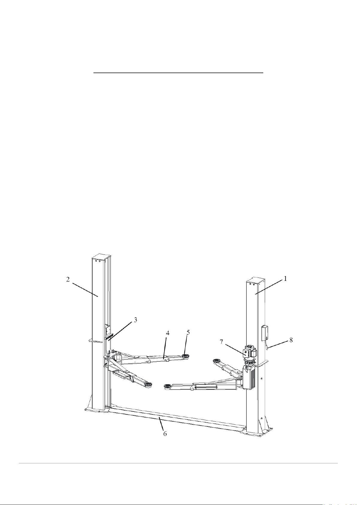
Lift Description
The lift is suitable for lifting motor vehicles having maximum weight as described
in the nameplate on the power side column of the lift. All mechanical parts
such as columns, carriages and lift arms have been built in steel plate to make
the frame stiff and strong while keeping a low weight. The electro hydraulic
operation is described in detail in chapter 8.
This chapter describes the lift’s principal elements, allowing the user to be
familiar with the machine. As shown in gure 2, the lift is composed of two
columns: power-side column (1) and off-side column (2), each equipped with a
carriage (3) and a pair of lifting arms (4) with the adaptor (5) anchored to the
ground by means of base plates of columns. The base plate (6) is used to protect
routed lines between columns. Raising motion is carried out by pushing the lifting
button on a power unit (7) which delivers the hydraulic uid to cylinders inside
the columns to act on the chain system to raise the lift. Lowering the vehicle
by pushing down the lowering handle on the power unit while holding down the
safety lock handle (8). The synchronization is controlled by the equalizer cables.
The arm safety can be engaged automatically when the lift is raised.
Figure 2 – Lift
Lift Description 11
BP10000
Page 12

Technical Specication
5.1 Size And Main Features
CAPACITY 10000 lbs
Max. stroke 37”
Max. lifting height with no pad extension 77 3/8”
Min. adaptor height 4”
Overall height 111 7/8”
Overall width 139 1/8”
Lifting time 65 S
Lowering time 50 S
Noise level 75 dB(A)/1m
Working temperature -10 °C - 40 °C
Average weight of package 1620 lbs
5.2 Electric Motor
Voltage 220V/60Hz/1Ph
Power 2.2kw
N° Poles 2
Speed 3450 rpm
Motor enclosure type B14
Insulation class IP 54
Motor connection must be carried out referring to the attached wiring diagrams
the gure 6. The motor direction of rotation is shown in the label placed on
the motor. Before use of the lift, make sure to check if the motor specication
shown in the nameplate of the motor conforms to the local electric supply. If
there is over 10% uctuation on the electrical power supply, it is suggested to
use the voltage stabilizer to protect the electrical components and system from
overloading.
Technical Specification 12
BP10000
Page 13

5.3 Pump
Type Gear
Flow rate 2.1 cm
Continuous working pressure 200 bar
Peak pressure 220 bar
3
/g
Figure 3 – Layout
Technical Specification 13
BP10000
Page 14
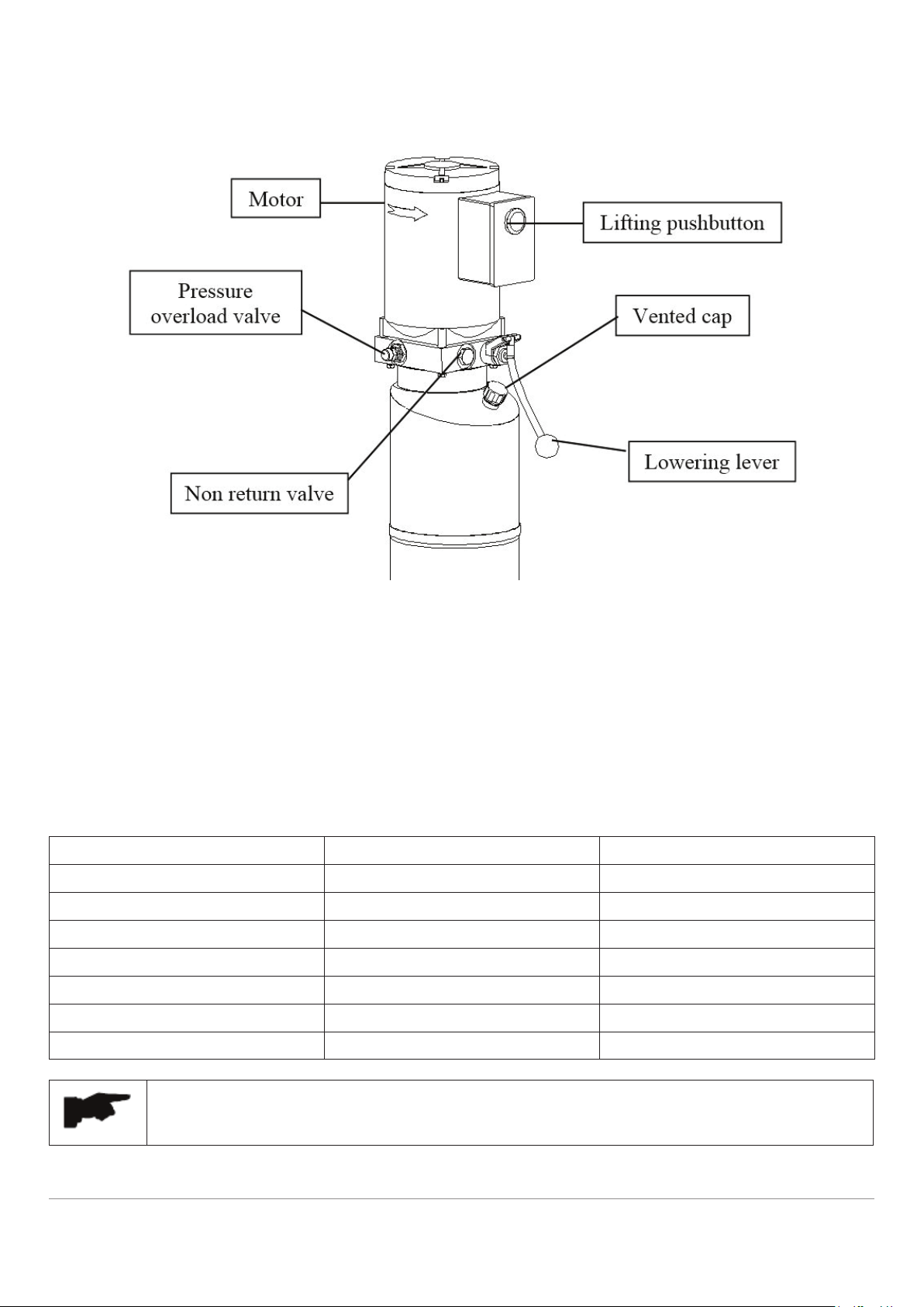
5.4 Hydraulic Power Unit
Figure 4 – Hydraulic Power Unit
5.5 Oil
Use wear proof oil for hydraulic drive, in conformity with ISO 6743/4 rules (HM
class). The oil with features similar to those shown in the table is recommended.
Test standards Features Value
ASTM D 1298 Density 20°C 0.8 kg/l
ASTM D 445 Viscosity 40°C 32 cSt
ASTM D 445 Viscosity 100°C 5.43 cSt
ASTM D 2270 Viscosity index 104 N°
ASTM D 97 Pour point ~ 30 °C
ASTM D 92 Flash point 215 °C
ASTM D 644 Neutralization number 0.5 mg KOH/g
Change hydraulic oil at 1 year intervals
Technical Specification 14
BP10000
Page 15

Figure 5 - Hydraulic Plan
1 Oil lter 6 Hydraulic cylinder
2 Gear pump 7 Pressure overload valve
3 Flow restrictor 8 Manual lowering valve
4 Non return valve 9 Motor
5 Lowering speed control valve 10 Startup valve
Technical Specification 15
BP10000
Page 16

Figure 6 – Electrical Diagram (220V/50Hz/60Hz/1Ph)
Technical Specification 16
BP10000
Page 17

Safety
Read this chapter carefully and completely because it contains important
information for the safety of the operator and the person in charge of
maintenance.
The lift has been designed and built for lifting vehicles and
making them stand above level in a closed area. Any other use
is forbidden.
The manufacturer is not liable for possible damages to people,
vehicles or objects resulting from an improper or unauthorized
use of the lift.
For operator and people safety, a square space for a safety area at least 3 feet
free away from the lift must be vacated during lifting and lowering. The lift must
be operated only from the operator’s control site in this safety area.
Operator’s presence under the vehicle, during working, is only admitted when
the vehicle is lifted and the safety lock is engaged.
Never use the lift when safety devices are off-line. People, the
lift, and the vehicles lifted can be seriously damaged if these
instructions are not followed.
6.1 General Warnings
The operator and the person in charge of maintenance must follow accidentprevention laws and rules in force in the country where the lift is installed.
They also must carry out the following:
• Neither remove nor disconnect hydraulic, electric or other safety devices;
• Carefully follow the safety indications applied on the machine and included
in the manual;
• Observe the safety area during lifting;
• Be sure the motor of the vehicle is off, the gear engaged and the parking
brake put on;
Safety 17
BP10000
Page 18

• Be sure only authorized vehicles are lifted without exceeding the maximum
lifting capacity;
• Verify that no one is on the arms during lifting or standing.
6.2 Safety Device
To avoid overloading and possible breaking, the following safety devices have
been used:
• A pressure overload valve built inside the hydraulic power unit to prevent
excessive weight.
The pressure overload valve has been preset by the
manufacturer to a proper pressure. DO NOT try to adjust it to
overrun the rated lifting capacity.
• Mechanical safeties built in each carriage with automatic engagement for
lifting safety.
It is strictly forbidden to modify any safety device. Always
ensure the safety device for proper operation during the service.
Safety 18
BP10000
Page 19

6.3 Safety Signs
All safety warning signs (ref. gure 7) displayed on the lift are with the purpose
to draw the operator’s attention to dangerous or unsafe situations. The labels
must be kept clean and they have to be replaced if detached or damaged. Read
the meaning of the labels carefully and memorize it.
Figure 7 – Safety Signs
Safety 19
BP10000
Page 20

Installation
Only skilled technicians, appointed by the manufacturer, or by
authorized dealers, must be allowed to carry out installation.
Serious damage to people and to the lift can be caused if
installations are made by unskilled personnel.
Always refer to the exploded views attached during installation.
7.1 Tool Required
Rotary Hammer Drill D.20 Hex-Key/Allen Wrench Set
Masonry Bit Crow Bar For Shim Installation
Hammer Chalk Line
Level Medium Cross Screwdriver
Open-End Wrench Set Medium Flat Screwdriver
Medium Crescent Wrench Tape Measure
7.2 Checking For Room Suitability
The lift has been designed to be used in covered and sheltered places free of
overhead obstructions. The place of installation must not be next to washing
areas, painting workbenches, solvent or varnish deposits. The installation
near to rooms, where a dangerous situation of explosion can occur, is strictly
forbidden. The relevant standards of the local Health and Safety at Work
regulations, for instance, with respect to minimum distance to wall or other
equipment, escapes and the like, must be observed.
7.3 Lighting
Lighting must be carried out according to the effective regulations of the place of
installation. All areas next to the lift must be well and uniformly lit.
Installation 20
BP10000
Page 21

7.4 Floor Requirement
The lift MUST be installed on 3000 PSI concrete with a minimum 4” thickness.
New concrete must be adequately cured by at least 20 days minimum.
Specications of concrete must be adhered to. Failure to do so
could cause lift failure resulting in personal injury or death.
A level oor is suggested for proper installation. Small
differences in oor slope may be compensated for by proper
shimming. Any major slope change will affect the level lifting
performance. If a oor is of questionable slope considering to
pour the new concrete slab.
7.5 Site Layout
• Now locate the lift according to the oor plan the gure 8, use a carpenters
chalk line to layout a grid for the column locations.
• After the column locations are properly marked, use a chalk or crayon to
make an outline of the columns on the oor at each location using the
column base plates as a template.
• Double check all dimensions and make sure that the bases of each column
are square and aligned with the chalk line.
Figure 8 – Floor Plan
Installation 21
BP10000
Page 22

7.6 Anchoring Columns
• Use the base plate on the column as a guide, drill each hole in the concrete
approximately 6” deep with
the rotary hammer drill D.20.
To assure full holding power,
do not ream the hole or allow
drill to wobble;
• After drilling, remove dust
thoroughly from each hole
using compressed air and/or
wire brush. Make certain that
the column remains aligned
with the chalk line during this
process;
• Assemble the washers and
nuts on the anchors then
tap into each hole with a
hammer until the washer
rests against the base plate.
Be sure that if shimming is required that enough threads are left exposed;
Fig. 9
• If shimming is required, insert the shims as necessary under the base plate
so that when the anchor bolts are tightened, the columns will be plumb;
• With the shims and anchor bolts in place, tighten by securing the nut to
the base. DO NOT use an impact wrench for this procedure;
• Before anchoring the nal column, lay out the cover plate and use it for
reference. Check measurements and alignment before drilling.
• Anchor the nal column as outlined in above steps;
• Check to make sure that the columns for square-ness and plumb are as
shown in the gure 9.
The requirements for column’s square-ness and plumb must be
adhered to. Failure to do so could cause lift failure resulting in
personal injury or death.
Installation 22
BP10000
Page 23

7.7 Routing The Equalizer Cables
The equalizer cables should be checked weekly for equal
tension. Failure to do this will cause uneven lifting. The cables
should always be adjusted so that they are equal tension
when resting on the safety locks.
• Use an appropriate lifting equipment to raise the carriage to the rst latch
position. Be sure the carriage is engaged securely before attempting to
route the equalizer cables. Carriages must be equal height from the oor
before proceeding;
• With the carriages in
equal height, t the
cable end-ups through
the small holes of the
carriages (ref. g. 10):
• Route the equalizer
cables referring to
the diagram (g. 10).
Make sure the cables
in the place on the
pulleys. Make sure
the cables routed
properly;
• After the equalizer
cables have been
routed, adjust the
nuts M12 to make
each cable in equal
tension;
Installation 23
BP10000
Page 24

7.8 Routing The Safety Release Cable
Assemble the safety cable from offside safety assembly, pay
attention to the connecting direction of safety cable.
• Install the cable pulley to the off-side column (ref.
g. 11);
• Feed the end of cable through the slot of safety rack;
• Route the cable through cable pulley, make sure
cable is routed at the top of the pulley and inside the
column (ref. g. 11).
• Continue routing the cable to the power-side column
referring to the diagram (g. 12). Make sure the
cables routed on the guides mounted previously on
the columns.
• Install the cable pulley in upper slot of the power-side column (ref. g. 13);
• Feed another end of the cable through the upper slot and make sure cable
is routed at the top of the pulley and inside the column (ref. g, 13);
• Slip the end of the cable through the hole of safety hook; tighten the M12
nut (ref. g, 13).
Installation 24
BP10000
Page 25

7.9 Installation Of Power Unit
• Attach the power unit onto the bracket on the power
side column;
• Secure it using nuts M10X20, the locking washers
D.10 and washers D. 10.
7.10 Connection Of Hydraulic Hoses
When routing the hydraulic hose, make sure that the hose is
clear of any moving part. Make sure to keep the hoses clean
from dust.
Make sure not to over-tighten the hose ttings so as to result in
oil leakage.
• Clean the hoses and ttings;
• Inspect all threads for damage and make sure that all hose ttings are in
good condition;
• Route the hoses referring the gure 15;
• Tighten the hose ttings thoroughly.
• Be sure to route the hydraulic hose and electric wire inside smaller
protective cover under the ramp as gure 16. Then x the cover on the
oor by supplied screws. Finally install the ramp.
Installation 25
BP10000
Page 26

7.11 Installation Of Floor Plate
• Drill D.10 holes using the holes in the plate as the guide;
• Following drill steps used when anchoring columns;
• Tighten by securing the nut to the plate.
Installation 26
BP10000
Page 27

7.12 Make The Electrical Connection
The hookup work must be carried out by a qualied electrician.
Make sure that the power supply is right.
Make sure the connection of the phases is right. Improper
electrical hook-up can damage motor and will not be covered
under warranty.
Make sure the lift is ground well.
It is strictly forbidden to use 60Hz motor on 50Hz power supply.
Never operate the motor on the power less than 208V. Motor
damage may occur.
• Make the electric hookup to the hydraulic power unit referring to the wiring
diagram (g. 6);
• Make sure to install a proper circuit breaker on the circuit (DZ47-63/
D32A/2P is suggested for single phase 208-240V);
• Make sure the lift is grounded well.
7.13 Oil Filling And Bleeding
DO NOT run power unit without oil. Damage to pump can occur.
If motor gets hot or sounds peculiar, stop immediately and
recheck the electric connection.
If the vented cap is lost or broken, order the replacement. The
oil tank must be vented well.
• Use the hydraulic uid recommended in the chapter 5.5;
• Remove the vented cap on the oil tank and pour oil in the tank about 10
liters;
• Cycle the lift up and down several times to ensure latches click together
and all air is removed from the system;
• To lower the lift, both latch releases must be manually released. Latches will
automatically reset once the lift ascends approximately 16” from base;
• If the latches click out of synchronization, tighten the equalizer cable on
the column that clicks later;
• Fill the more uid if necessary till the tank is full.
Installation 27
BP10000
Page 28

7.14 Installation Of Arms
• Raise the carriages to a convenient
height;
• Install the swing arms on the carriages
using the included pins as shown;
• Check for proper engagement of
the arm lock – the teeth on the lock
should fully engage the gear on the
arm. If arm pins are not tting, pull
up on arm lock to allow slack for the
arm to move around in the carriage,
allowing the arm pin to t easier.
7.15 Check Before Start-Up
7.15.1 GENERAL CHECKS
• Make sure that the columns are plumb;
• Make sure the lift anchored to the ground and all anchor bolts tightened.
• Make sure the electrical system feeding voltage is equal to that specied in
the nameplate on the motor;
• Make sure the electric system connection in conformity of the electric plan
shown as the electric diagram (g. 6) and for proper grounding.
• Particularly, below checks must be followed
7.15.2 MECHANICAL SAFETIES FOR PROPER INSTALLATION
• Check to make sure that safety latches will properly engage and disengage
by manual release;
• If latches click out of synchronization, tighten the cable on the one that
clicks later.
Installation 28
BP10000
Page 29

7.15.3 EQUALIZER CABLE FOR PROPER INSTALLATION
The equalizer cables should be checked weekly for equal
tension. Failure to do this will cause uneven lifting. The cables
should always be adjusted so that they are equal tension when
resting on the safety locks.
• Raise the carriages to check the equalizer cable
tension by grasping the adjacent cables between
the thumb and the forenger so that you can just
pull the cables together (ref. g. 18);
• Adjust the cable tensions if necessary.
7.15.4 HYDRAULIC SYSTEM FOR PROPER OPERATION
• Make sure that the cylinder is located in the center hole in the base of
column;
• Proper oil level in the tank, rell if needed;
• Raise the lift to the full height and keep the motor running for 5 seconds
and check all hoses connections to make sure no leakage. Tighten the
connections or reseal if necessary;
• Check the lift for reaching its maximum height;
• Repeat the air bleeding of cylinders if necessary.
7.16 Check With Load
WARNING: please follow carefully the instructions in the
coming paragraph for avoiding damages on the lift.
Carried out two or three complete cycles of lowering and lifting with the vehicle
loaded:
• Repeat the checks provided for by 7.15.
• Check no strange noise during lifting and lowering.
Installation 29
BP10000
Page 30

Operation And Use
NEVER operate the lift with any person or equipment below.
NEVER exceed the rate lifting capacity.
NEVER lift a vehicle in any manner with less than four arms.
Always ensure that the mechanical locks are engaged before
any attempt is made to work on or near the vehicle.
Always lift a vehicle on the lifting pads.
NEVER leave the lift in an elevated position unless the
safeties are engaged.
If an anchor bolt becomes loose or any component of the lift
is found to be defective, DO NOT USE THE LIFT until repairs
are made.
8.1 Controls
Controls for operating the lift are:
LIFTING BUTTON (1)
• When pressed, the power unit is running
and the lift can be raised to a desired
height until the button is released.
LOWERING LEVER (2)
• If the mechanical locks are not released,
the lift will lower to the nearest lock
position.
• If both mechanical locks are released, press the lower lever, the lift will
lower to the desired height under its weight and the load lifted until the
lever is released.
Operation And Use 30
BP10000
Page 31

Lift operation can be summarized into four steps:
8.2 Vehicle Positioning
• Positioning the vehicle between columns;
• Adjust lift arms so that the vehicle is positioned with the center gravity
between the pads. Make sure the arm safeties are engaged;
• Raise the lift by pressing the lifting button until the lifting adaptors contact
underside of the vehicle;
• Make sure the vehicle is secured.
8.3 Lifting
• Raise the lift by pushing the lifting button until reaching the desire height.
8.4 Standing
• Press the lowering lever to engage the nearest lock position;
• Always ensure that the lock in each column is engaged before any attempt
is made to work on or near the vehicle.
8.5 Lowering
• Raise the lift a little bit by pushing the lifting button to clear off the
mechanical locks;
• Release the locks manually and lower the lift by pressing the lowering lever
at the same time;
• Before removing vehicle from the lift area, position the lift arms to and
pads to provide an obstructed exit;
• Never drive over the lift arms.
Operation And Use 31
BP10000
Page 32

Maintenance
Only trained people who know how the lift works, can be
allowed to service the lift.
To service properly the lift, the following has to be carried out:
• use only genuine spare parts as well as equipment suitable for the work
required;
• follow the scheduled maintenance and check periods shown in the manual;
• discover the reason for possible failures such as too much noise,
overheating, oil blow-by, etc.
• refer to documents supplied by the manufacture or dealer to carry out
maintenance.
Before carrying out any maintenance or repair on the lift,
disconnect the power supply.
9.1 Ordinary Maintenance
The lift has to be properly cleaned at least once a month using self-cleaning
clothes.
The use of water or inammable liquid is strictly forbidden
Be sure the rod of the hydraulic cylinders is always clean and not damaged
since this may result in leakage from seals and, as a consequence, in possible
malfunctions.
Maintenance 32
BP10000
Page 33

9.2 Periodic Maintenance
• Check hydraulic connections and hoses for leaks
• Check mechanical locks audibly and visually while
Daily pre-operation
Every 1 month
in operation
• Check arm locks
• Check bolts, nuts and screws are tight
• Check all cable connections, pins and bolts to
insure proper mounting
• Inspect all anchor bolts and retighten if necessary
• Check columns for squareness and plumb
• Check equalizer cable tension, adjust if necessary
• Check safety release cable, adjust it if necessary
• Check all arm pivot pins. Make sure they are
properly secured
Every 12 months
• Check all lifting pads, replace if necessary
• Lubricant columns with grease
• Check the hydraulic oil, ll or replace if necessary
• Check hydraulic systems for proper operation
• Verify that all components and mechanisms are
not damaged
• Verify the equalizer cables are not worn, change if
necessary
• Check the electrical system to verify that the
motors operate properly (this work must be
carried out by skilled electricians)
• Empty the oil tank and change the hydraulic oil
Maintenance 33
BP10000
Page 34

Troubleshooting
A list of possible troubles and solutions is given below:
Trouble: Possible Cause: Solution:
There is no power Check Power on to restore if necessary
The lift does not
work
The lift does not
raise
The lifting
capacity is not
sufcient
The electrical wires are
disconnected
The circuit breaker are
blown
The lift is overloaded Check the vehicle weight
The motor direction of
rotation is not correct.
The oil in the power
unit is not sufcient.
The UP button is faulty.
The lowering valve
does not close.
The suction tube or
pump lter is dirty.
Presence of air in the
hydraulic system
The pump is faulty Check the pump and replace if needed.
Oil leakages in
hydraulic circuit
Reconnect
Check for correct voltage
Replace
Interchange the two phases on the
main switch
Add some hydraulic oil
Check UP button and connection for
proper operation. Replace if needed
Check and clean, if dirty or replace if
faulty
Check and clean if needed.
Bleed the hydraulic system
Check the circuit for any leakage
The lift does not
lower when the
lowering lever and
the safety release
lever are pressed
The lift does not
lower smoothly
The lowering valve
does not work properly
The safety release
cables are not in the
same tension.
Presence of air in the
hydraulic system
Lubrication of sliders is
not enough.
Sliders are damaged Replace
Check the valve and replace if needed.
Readjust the cable.
Bleed the hydraulic system
Grease
* If the problems remain unsolved, call for technical support.
Troubleshooting 34
BP10000
Page 35

Parts Lists
Lift
ITEM PART NO. DESCRIPTION QTY
1 Z11G101000 Power-side column 1
2 Z11G102000 Off-side column 1
3 Z11G320000 Short arm assembly 2
4 Z11G310000 Long arm assembly 2
5 Z31B330000 Lifting adaptor 4
6 Z11G500100 Arm shaft 4
Parts Lists 35
BP10000
Page 36

ITEM PART NO. DESCRIPTION QTY
7 Z11G410101 Base plate 1
8 Z11G510100 Equalizer steel cable 2
9 Z11G510200 Safety release wire 1
10 Z11G320001 Welded handle 2
11 Z11H310001 Welded handle 2
12 Z11H310002 Tool box 2
13 Z11B503101 Pipe clamp 2
14 0212023 Seeger D.38 4
15 0203025 Nut M16 - GB/T6170 4
16 0201062 Screw M10X20 - GB/T5783 2
17 0208007 Locking washer D.10 - GB/T93 2
18 0205011 Washer D.10 - GB/T97.1 2
19 0202043 Screw M8X12 - GB/T70.1 8
20 0206036 Screw M6X8 - GB/T818 2
21 0302014 Hydraulic power unit 1
Parts Lists 36
BP10000
Page 37

Powerside Column
ITEM PART NO. DESCRIPTION QTY
1 Z11G111000 Main Column 1
2 Z11G210000 Main carriage assembly 1
3 Z11G131100 Top cover 1
4 Z31A110004 Roller 2
5 Z11G520000 Pulley base 1
6 Z11B113000 Safety rack 1
7 Z11B114000 Safety hook 1
8 Z11B110002 Connection rod 1
9 Z31A110001 Shaft 1
10 Z31A110002 Spring 1
Parts Lists 37
BP10000
Page 38

ITEM PART NO. DESCRIPTION QTY
11 Z31A110005 Lower pulley 2
12 Z31A110003 ABS cover with hole 1
13 Z11B110004 Upper pulley 1
14 Z11G161100 Support 1
15 Z11GY70000 Hydraulic cylinder 1
16 0210112 Bush SF-1 3
17 0213038 Pin 2.5X26 1
18 0213075 Pin 4X50 2
19 0213035 Pin 4X30 2
20 0213044 Pin 2X20 3
21 0205011 Washer D.10 - GB/T97.1 2
22 0201061 Screw M12X30 - GB/T5783 4
23 0205013 Washer D.12 - GB/T97.1 6
24 0204007 Nut M12 - GB/T889.1 4
25 0203023 Nut M12 - GB/T6170 2
26 0202136 Screw M5X65 - GB/T70.1 1
27 0204002 Nut M5 - GB/T889.1 1
28 0206036 Screw M6X8 - GB/T818 2
29 0206001 Screw M8X12 - GB/T818 2
30 0606216 Handle cover 1
31 Z11G211000 Main carriage 1
32 Z11G210001 Slider 8
33 Z11G210002 Cover 1
34 Z23B711001 Rubber pad 1
35 Z23A200003 Toothed gear 2
36 Z11G200004 Safety release pin 2
37 Z23A200005 Spring 2
38 Z23A200006 Release ring 2
39 0213052 Elastic pin 6X40 2
40 0212004 Seeger D.25 - GB/T894.1 2
41 0206036 Screw M6X8 - GB/T818 2
42 0202045 Screw M8X20 - GB/T70.1 2
43 0215134 Chain BL646X75 1
Parts Lists 38
BP10000
Page 39

Offside Column
ITEM PART NO. DESCRIPTION QTY
1 Z11G121000 Slave Column 1
2 Z11G220000 Slave carriage assembly 1
3 Z11G131100 Top cover 1
4 Z31A110004 Roller 2
5 Z31A110003A ABS cover 1
6 Z11G520000 Pulley base 1
7 Z11G161100 Support 1
8 Z11B122000 Safety rack 1
Parts Lists 39
BP10000
Page 40

ITEM PART NO. DESCRIPTION QTY
9 Z11B123000 Safety hook 1
10 Z11B110002 Connection rod 1
11 Z31A110001 Shaft 1
12 Z31A110002 Spring 1
13 Z31A110005 Lower pulley 2
14 Z11B110004 Upper pulley 1
15 Z11GY70000 Hydraulic cylinder 1
16 0210112 Bush SF-1 3
17 0213038 Pin 2.5X26 1
18 0213035 Pin 4X30 4
19 0213044 Pin 2X20 1
20 0213054 Pin 2X16 2
21 0205011 Washer D.10 - GB/T97.1 2
22 0201061 Screw M12X30 - GB/T5783 4
23 0205013 Washer D.12 - GB/T97.1 4
24 0204007 Nut M12 - GB/T889.1 4
25 0206036 Screw M6X8 - GB/T818 2
26 0206001 Screw M8X12 - GB/T818 2
27 0202136 Screw M5X65 - GB/T70.1 1
28 0204002 Nut M5 - GB/T889.1 1
29 Z11G221000 Slave carriage 1
30 Z11G210001 Slider 8
31 Z11G210002 Cover 1
32 Z23B711001 Rubber pad 1
33 Z23A200003 Toothed gear 2
34 Z11G200004 Safety release pin 2
35 Z23A200005 Spring 2
36 Z23A200006 Release ring 2
37 0213052 Elastic pin 6X40 2
38 0212004 Seeger D.25 - GB/T894.1 2
39 0206036 Screw M6X8 - GB/T818 2
40 0202045 Screw M8X20 - GB/T70.1 2
41 0215134 Chain BL646X75 1
Parts Lists 40
BP10000
Page 41

Arm & Adaptor
ITEM PART NO. DESCRIPTION QTY
1 Z11G310000 Long arm assembly 1
2 Z11G320000 Short arm assembly 1
3 Z11G311000 Long arm frame 1
4 Z11G312000 Long arm outer extension 1
5 Z23A310001 Anti-rotating gear 2
6 0201050 Screw M10X35 - GB/T5783 6
7 0206061 Screw M8X12 - GB/T70.2 3
8 Z31B330000 Lifting adaptor 2
Parts Lists 41
BP10000
Page 42

ITEM PART NO. DESCRIPTION QTY
9 0202032 Screw M6X16 - GB/T70.1 1
10 Z31B330001 Round rubber pad 1
11 Z31A321000 Pad support 1
12 Z11G321000 Short arm frame 1
13 Z11G322000 Short arm middle extension 1
14 Z11G323000 Short arm outer extension 1
Parts Lists 42
BP10000
Page 43

Hydraulic Line
ITEM PART NO. DESCRIPTION QTY
1 0302014 Hydraulic power unit 1
2 Z11GY70000 Hydraulic cylinder 2
3 7B-04-98 Union 2
Parts Lists 43
BP10000
Page 44

ITEM PART NO. DESCRIPTION QTY
4 6432-Y1.5 Flow restrictor 2
5 7530-Y-3 Spring 2
6 0303120 90° tting 1/4 2
7 0303002 90° union 1/4 (1BT9-04SP) 2
8 0303021 Tee union 1/4 1
9 WW3150 Hydraulic pipe L=3150 1
10 ZZ1480 Hydraulic pipe L=1480 2
11 Z11GY70100 Cylinder liner 1
12 Z11GY70001 Piston 1
13 Z11GY70004 Piston rod 1
14 Z11GY70002 Cylinder guiding cover 1
15 Z11GY70006 Spacer 1
16 0312014 Gasket 70X50X22.4 1
17 0309143 O-ring 37.5X3.55 1
18 0309050 O-ring 70X3.1 1
19 0311007 Scraper 38X46X5/6.5 1
20 0306086 Silencer 1/4 1
21 0211032 Seeger D.25 1
Parts Lists 44
BP10000
Page 45

Warranty
This item is warranted for ve (5) years on structural
components, two (2) years on hydraulic cylinders, and one (1)
year on electric or air / hydraulic power units from invoice date.
Wear items are covered by a 90 day warranty.
This LIMITED warranty policy does not include a labor warranty.
NOTE: ALL WARRANTY CLAIMS MUST BE PRE-APPROVED BY THE MANUFACTURER TO BE
VALID.
The Manufacturer shall repair or replace at their option for this period those parts returned to
the factory freight prepaid, which prove after inspection to be defective. This warranty will not
apply unless the product is installed, used and maintained in accordance with the Manufacturers
installation, operation and maintenance instructions.
This warranty applies to the ORIGINAL purchaser only, and is non-transferable. The warranty
covers the products to be free of defects in material and workmanship but, does not cover normal
maintenance or adjustments, damage or malfunction caused by: improper handling, installation,
abuse, misuse, negligence, carelessness of operation or normal wear and tear. In addition, this
warranty does not cover equipment when repairs or alterations have been made or attempted to
the Manufacturer’s products.
THIS WARRANTY IS EXCLUSIVE AND IS LIEU OF ALL OTHER WARRANTIES EXPRESSED OR IMPLIED
INCLUDING ANY IMPLIED WARRANTY OR MERCHANTABILITY OR ANY IMPLIED WARRANTY OF
FITNESS FROM A PARTICULAR PURPOSE, AND ALL SUCH IMPLIED WARRANTIES ARE EXPRESSLY
EXCLUDED.
THE REMEDIES DESCRIBED ARE EXCLUSIVE AND IN NO EVENT SHALL THE MANUFACTURER, NOR
ANY SALES AGENT OR OTHER COMPANY AFFILIATED WITH IT OR THEM, BE LIABLE FOR SPECIAL
CONSEQUENTIAL OR INCIDENTAL DAMAGES FOR THE BREACH OF OR DELAY IN PERFORMANCE
OF THIS WARRANTY. THIS INCLUDES, BUT IS NOT LIMITED TO, LOSS OF PROFIT, RENTAL OR
SUBSTITUTE EQUIPMENT OR OTHER COMMERCIAL LOSS.
PRICES: Prices and specications are subject to change without notice. All orders will be invoiced
at prices prevailing at time of shipment. Prices do not include any local, state or federal taxes.
RETURNS: Products may not be returned without prior written approval from the Manufacturer.
DUE TO THE COMPETITIVENESS OF THE SELLING PRICE OF THESE LIFTS, THIS WARRANTY POLICY
WILL BE STRICTLY ADMINISTERED AND ADHERED TO.
Warranty 45
BP10000
 Loading...