

Page 1

Atlas AVM JR.
Installation and Programming Manual
Page 2

Introduction
Legal Notice
Key System US provides this document "as is," with no representations or warranties, either explicit
or implied, including but not limited to the implied warranties of merchantability, title, or fitness for a
particular purpose.
Key System US reserves the right to make changes in product software, hardware, or documentation
at any time, with no obligation to inform any persons or entities of such changes. Every attempt has
been made to ensure the accuracy of this document. However, Key System US assumes no
responsibility for any losses, whether electronic, financial, or other, that might accrue from
inadvertent inaccuracies that the software or documentation might contain.
Some states or jurisdictions do not allow disclaimer of explicit or implicit warranties in certain
situations. Therefore, this statement might not apply to you.
Copyright © 2000. Key System US. All rights under copyright reserved.
The AVM JR. engine is covered by patent pending and copyright protection.
The contents of this document may not be duplicated by any means, whether electronic, graphic, or
mechanical, including, but not limited to, photocopying, recording, taping, or information recording
and retrieval systems, for any purpose but the original purchaser's personal use, without prior written
permission of Key System US.
Trademark Information
AVM JR., Key System US, and Atlas IIE are trademarks of KS Telecom Inc.
All other trademarks are the property of their respective owners.
Software Version
This manual is for AVMJR software version 4.xx released April 1, 2000
Documentation release April 1, 2000
Key System US
4910 Dyer Blvd., West Palm Beach, Florida 33407
II Atlas AVM JR. Installation and Programming Manual
Page 3

Introduction
Table Of Contents
Table Of Contents ...................................................................................................................... III
1. INTRODUCTION..............................................................................................................1-1
1.1 FEATURES AND SERVICES..............................................................................................1-2
1.1.1 System Features....................................................................................................1-2
1.1.2 Automated Attendant Features.............................................................................1-3
1.1.3 Voice Mail Features.............................................................................................1-5
1.2 ABOUT THIS MANUAL ...................................................................................................1-7
2. DESCRIPTION AND INSTALLATION .........................................................................2-1
2.1 BASE SYSTEM ...............................................................................................................2-2
2.2 PHYSICAL DESCRIPTION ................................................................................................2-2
2.2.1 Side Panel.............................................................................................................2-3
2.2.2 Front Panel...........................................................................................................2-3
2.3 INSTALLATION...............................................................................................................2-4
2.3.1 Unpacking ............................................................................................................2-4
2.3.2 Installing the AVM JR. .........................................................................................2-5
2.3.3 Expanding the System...........................................................................................2-7
2.4 SPECIFICATIONS...........................................................................................................2-10
3. DTMF PROGRAMMING.................................................................................................3-1
3.1 ENTERING AND EXITING THE PROGRAMMING MODE.....................................................3-1
3.2 FIRST TIME PROGRAMMING CHECKLIST........................................................................3-2
3.3 DEFINING KSU PARAMETERS .......................................................................................3-2
3.4 SETTING THE TIME AND DATE.......................................................................................3-8
3.5 PROGRAMMING THE OPERATIONAL MODE ....................................................................3-8
3.6 PROGRAMMING THE VOICE MAIL................................................................................3-11
3.6.1 Creating Mailboxes............................................................................................3-11
3.6.2 Creating Mailbox Groups...................................................................................3-12
3.6.3 Notification.........................................................................................................3-13
3.7 PROGRAMMING THE AUTOMATED ATTENDANT SCRIPT MENU....................................3-16
3.7.1 Recording Script Messages ................................................................................3-16
3.7.2 Programming Script Messages...........................................................................3-17
3.7.3 Directory Listing Programming.........................................................................3-23
3.7.4 Reset Script Message Programming to Default..................................................3-24
3.7.5 Supervised, Semi-Supervised and Non-Supervised Transfers ............................3-25
3.8 ADDITIONAL FEATURES...............................................................................................3-27
3.8.1 Changing Passwords..........................................................................................3-27
3.8.2 Activate Force Reorganize .................................................................................3-28
3.8.3 Changing to/from Day Light Saving Time..........................................................3-28
3.8.4 Changing the Operational Mode........................................................................3-29
Atlas AVM JR. Installation and Programming Manual III
Page 4

Introduction
3.8.5 Playing a System Message..................................................................................3-29
3.8.6 Listening to the Software Version Number.........................................................3-29
3.8.7 Listening to the System Time and Date...............................................................3-29
3.8.8 Resetting the System...........................................................................................3-30
3.8.9 Adjusting Recording Length...............................................................................3-30
4. PROGRAMMING BY COMPUTER...............................................................................4-1
4.1 CONNECTING THE COMPUTER TO THE AVM JR............................................................4-1
4.2 SYSTEM REQUIREMENTS...............................................................................................4-2
4.3 INSTALLING THE VUP ...................................................................................................4-3
4.4 STARTING VUP.............................................................................................................4-3
4.5 DEFINING THE AVM JR. PARAMETERS.........................................................................4-5
4.5.1 Defining PBX Parameters....................................................................................4-5
4.5.2 Defining System Parameters ................................................................................4-9
4.6 PROGRAMMING THE VOICE MAIL................................................................................4-11
4.6.1 Viewing the Mailbox List....................................................................................4-11
4.6.2 Creating Mailboxes............................................................................................4-12
4.6.3 Changing the Parameters of an Existing Mailbox .............................................4-14
4.6.4 Deleting an Existing Mailbox.............................................................................4-15
4.6.5 Organizing Mailbox Groups...............................................................................4-15
4.6.6 Setting Notification Parameters .........................................................................4-17
4.7 PROGRAMMING THE AUTOMATED ATTENDANT...........................................................4-18
4.7.1 To program a script message .............................................................................4-18
4.7.2 Setting Up Different Script Menus Per Port.......................................................4-20
4.8 SETTING THE TIME, DATE AND OPERATION MODE......................................................4-22
4.8.1 Setting up Auto Mode.........................................................................................4-23
4.9 WORKING WITH CONFIGURATION FILES ......................................................................4-26
4.10 DOWNLOADING DATA TO THE AVM JR......................................................................4-26
4.11 VIEWING STATISTICAL INFORMATION STORED IN THE AVM JR. DATABASE...............4-27
4.12 PRINTING REPORTS......................................................................................................4-27
4.13 SAVING REPORTS ........................................................................................................4-28
4.14 GETTING HELP ............................................................................................................4-28
4.15 CLOSING THE VUP......................................................................................................4-28
5. USER OPERATING INSTRUCTIONS...........................................................................5-1
5.1 INTRODUCTION..............................................................................................................5-1
5.2 USER’S MAIN MENU .....................................................................................................5-1
5.3 RETRIEVE MESSAGE MENU...........................................................................................5-1
5.4 MAILBOX PARAMETERS ................................................................................................5-2
5.4.1 Record Greeting ...................................................................................................5-3
5.4.2 Record Name........................................................................................................5-3
5.4.3 Directory Listing ..................................................................................................5-3
5.4.4 Change Password.................................................................................................5-4
5.4.5 External Notification............................................................................................5-4
5.4.6 Pager Notification................................................................................................5-5
IV Atlas AVM JR. Installation and Programming Manual
Page 5

Introduction
5.4.7 Return to Previous Menu......................................................................................5-6
5.5 SEND MESSAGE.............................................................................................................5-6
5.6 RETURN TO AUTO ATTENDANT .....................................................................................5-6
5.7 QUICK REFERENCE GUIDE.............................................................................................5-7
6. TROUBLESHOOTING.....................................................................................................6-1
7. APPENDIX A .....................................................................................................................7-1
8. APPENDIX B......................................................................................................................8-1
9. APPENDIX C .....................................................................................................................9-1
10. APPENDIX D ...............................................................................................................10-1
SMDR E.................................................................................................................................10-1
SMDR-64/256........................................................................................................................10-2
SMDR-U (KDX-500).............................................................................................................10-3
11. APPENDIX E................................................................................................................11-1
E.1 KSX-32/64/128/256 DETAILED PROGRAMMING.........................................................11-1
E.1.1 Programming Voicemail Ports...........................................................................11-1
E.1.2 Programming the Station Group........................................................................11-1
E.1.3 Programming Direct Ring..................................................................................11-2
E.1.4 Programming Delayed Ringing..........................................................................11-3
E.2 KDX-500 DETAILED PROGRAMMING..........................................................................11-4
E.2.1 Programming Voicemail Ports...........................................................................11-4
E.2.2 Programming the Station Hunt Group...............................................................11-4
E.2.3 Programming Direct Ringing.............................................................................11-5
E.2.4 Programming Delayed Ringing..........................................................................11-6
Table of Figures
FIGURE 1-1 GENERAL VIEW..........................................................................................................1-1
FIGURE 2-1 OPTIONS FOR UPGRADING THE BASE SYSTEM..........................................................2-2
FIGURE 2-2 SIDE PANEL..............................................................................................................2-3
FIGURE 2-3 LED'S ON THE FRONT PANEL .....................................................................................2-3
FIGURE 2-4 ANALOG LINE CONNECTIONS .....................................................................................2-5
FIGURE 2-5 SYSTEM INSTALLATION ..............................................................................................2-7
FIGURE 4-1 RS-232 CABLE CONNECTION.....................................................................................4-2
FIGURE 4-2 VUP MAIN SCREEN ...................................................................................................4-4
FIGURE 4-3 PBX PARAMETERS EXTENSION SCREEN ....................................................................4-6
FIGURE 4-4 PBX PARAMETERS CALL TRANSFER SCREEN ............................................................4-7
FIGURE 4-5-5 PBX PARAMETERS SUPERVISION SCREEN ..............................................................4-8
FIGURE 4-6 SYSTEM PARAMETERS DIALOG BOX ........................................................................4-10
FIGURE 4-7LIST OF MAILBOXES DIALOG BOX.............................................................................4-12
Atlas AVM JR. Installation and Programming Manual V
Page 6

Introduction
FIGURE 4-8 NEW MAILBOX DIALOG BOX....................................................................................4-13
FIGURE 4-9 GROUP OF MAILBOXES DIALOG BOX........................................................................4-16
FIGURE 4-10 NOTIFICATION PARAMETERS DIALOG BOX.............................................................4-17
FIGURE 4-11 AUTO ATTENDANT SCRIPT MENU DIALOG BOX.....................................................4-19
FIGURE 4-12 SCRIPT OPENING SCREEN.......................................................................................4-21
FIGURE 4-13 DATE & TIME DIALOG BOX ...................................................................................4-22
FIGURE 4-14 AUTO MODE SCHEDULE.........................................................................................4-24
FIGURE 4-15 HOLIDAY SCHEDULE SCREEN.................................................................................4-25
FIGURE 10-1 SMDR-E DIAGRAM ...............................................................................................10-2
FIGURE 10-2 KSX 64/256 SMDR...............................................................................................10-3
FIGURE 10-3 KDX-500 SMDR DIP SWITCHES ...........................................................................10-4
FIGURE 10-4 KDX-500 SIDE CONNECTIONS...............................................................................10-4
VI Atlas AVM JR. Installation and Programming Manual
Page 7

1. INTRODUCTION
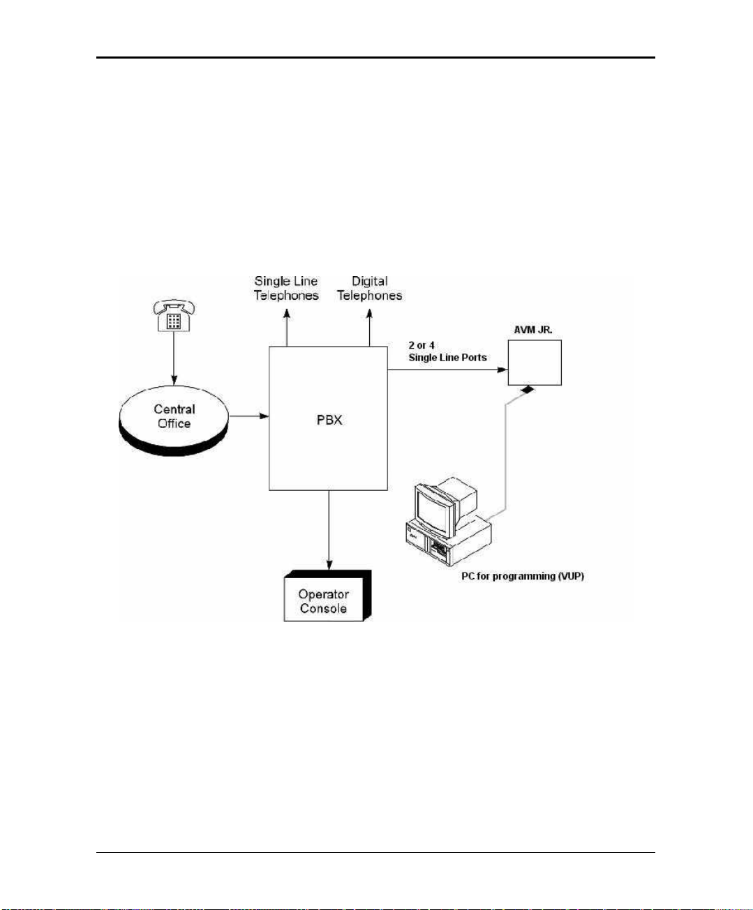
The AVM JR. is a small stand-alone Voice Mail/Automated Attendant system for
organizations that have between eight and eighty employees. Developed by KS
Telecom, a leader in the field of Telephone Equipment and Voice Processing
Systems. The AVM JR. incorporates state of the art technology, including DSP,
flash memory and SMT production.
Figure 1-1 General View
The AVM JR. is available in two or four port versions. It features 128 mailboxes
and provides from 2 hours and 40 minutes to up to 8 hours recording time.
The AVM JR. is designed to be integrated with all Key System US KSU's through
single line ports for voice and using the RS-232 serial port for SMDI integration.
The system administrator can program the AVM JR. by computer using the
Voicemail Utility Program (VUP) or by touch-tone telephone.
Atlas AVM JR. Installation and Programming Manual 1-1
Page 8

Introduction
Installing the AVM JR. is quick and easy. Just mount it on a wall next to the KSU
and connect it to the single line ports, the SMDR serial port, and the main power
supply with an external power adapter.
The AVM JR's voice mail system is ready for use immediately after the system
administrator completes a short procedure that includes setting up mailboxes,
notification type, system schedules and opening greetings. Each mailbox owner
can then set up his own personal mailbox parameters.
1.11.1 Features and ServicesFeatures and Services
The AVM JR. is a powerful voice mail system at an affordable price. It contains
most of the useful features and services provided by PC-based systems but at a
lower cost. The JR's features can be divided into three groups:
•
System
•
Automated Attendant
•
Voice Mail
1.1.1 System Features
•
Configuration
The AVM JR. comes with two ports and two hours and forty minutes of
recording time. The system administrator can upgrade the AVM JR. by:
−
Adding a two port expansion card to the motherboard to provide four ports
−
Inserting a memory card with two hours and forty minutes of storage space
to increase the total storage capacity to five hours and twenty minutes
−
Inserting a memory card with five hours and twenty minutes of storage
space to increase the total storage capacity to eight hours
•
Programming
The system administrator can program the AVM JR. by:
−
Touch-tone telephone using DTMF tones
−
Computer using the Voicemail Utility Program, a Windows-based
proprietary program developed by Key System US. The installer should
save a file containing the parameters set in each installation.
1-2 Atlas AVM JR. Installation and Programming Manual
Page 9

Introduction
•
Integration with your PBX
−
The AVM JR. integrates with the KSU through the SMDR RS-232 port
using SMDI signaling
•
Message Notification
The AVM JR. automatically notifies the mailbox owner of new messages in
different ways according to the system configuration. Notification may be
local (to an extension) or remote (to a telephone at a remote location, a cellular
telephone or a pager).
•
Security Passwords
The AVM JR. supports three types of passwords, each with four digits:
−
System Administrator. Gives access to all data stored in the AVM JR..
−
Operator. Gives access to the operating modes.
−
Mailbox. Gives access to individual mailboxes. The mailbox owner can
change the password any time.
1.1.2 Automated Attendant Features
The AVM JR.’s automated attendant answers incoming calls and, through a series
of recorded menus and telephone directories, helps the callers reach the desired
extensions.
•
Opening Greeting
The AVM JR. plays a pre-recorded greeting to callers. The opening greeting
usually includes the organization’s name, how to reach an extension,
department or operator, how to leave a message and how to access a directory.
During the greeting, callers can access a department by dialing a single digit,
dialing the extension number or holding for assistance.
•
Operating Modes
Depending on the time and the system schedule, the AVM JR. answers
external calls with one of four opening greetings:
Atlas AVM JR. Installation and Programming Manual 1-3
Page 10

Introduction
−
During normal business hours, the AVM JR. answers calls with a pre-
−
During non-working hours, the AVM JR. answers calls with a pre-
−
During holidays, the AVM JR. answers calls with a special greeting that
−
The system administrator can program part of the day mode as break time.
Day Mode
recorded daytime greeting. The daytime greeting enables the caller to
reach a requested extension, mailbox, department, directory or operator.
Night Mode
recorded nighttime greeting that enables the caller to leave a message in a
requested mailbox.
Holiday Mode
enables the caller to leave a message in a specific mailbox or in the
operator’s mailbox. The holiday mode can be activated by the operator
(password protected).
Break Mode
During break time, the AVM JR. answers calls with a special greeting that
enables the caller to leave a message in a specific mailbox or in the
operator’s mailbox.
•
System Schedules (Auto-Mode)
If your organization has operating hours that vary from day to day, the system
administrator can define the daily operating schedules on a weekly basis,
including daytime, nighttime and break time hours. When the Auto mode is
activated, the AVM JR. automatically switches between the day, night and break
modes according to your pre-defined schedule.
The operator can override the pre-defined system schedule and switch
manually to day, night, break, or holiday mode using a password.
•
Fax Detection
If the AVM JR. detects a fax tone (CNG) during the opening greeting, it
automatically transfers the call to the pre-defined fax extension.
1-4 Atlas AVM JR. Installation and Programming Manual
Page 11

Introduction
•
Directory
The system administrator can set up a directory containing the names and
extensions of all the organization’s employees. A caller can access this
directory by following instructions during the opening greeting.
•
Call Transfer
The system administrator can program the AVM JR. to detect the Call
Progress tones sent by the KSU and transfer the calls to extensions in one of
the following modes:
−
Non-Supervised. The AVM JR. transfers the call immediately without
verifying the status of the extension.
−
Supervised. The AVM JR. checks for a busy or answer signal before
transferring the call to the extension.
−
Semi-Supervised. The AVM JR. only checks for a busy signal before
transferring the call to the extension.
•
Answering on the First Ring
To avoid delays, the system administrator can set up the AVM JR. on each
individual port to answer incoming calls on the first ring.
•
Script Menus
The AVM JR. supports up to 25 script menus. A script menu is a recorded
announcement that can accept a digit entry (0-9) during playback. Based on
the digit entered, the AVM JR. can take one of the following actions:
−
Transfer the call to another script menu
−
Transfer the call to an extension or hunt group
−
Transfer the call to a mailbox or a mailbox group
−
Retrieve messages from a mailbox
−
Disconnect the line
1.1.3 Voice Mail Features
The AVM JR.’s Voice Mail system enables a caller to leave in any mailbox a
message recorded in his own voice. The mailbox owner can access his mailbox at
any time from any touch-tone telephone and listen to his messages. He can also
modify his mailbox parameters.
Atlas AVM JR. Installation and Programming Manual 1-5
Page 12

Introduction
•
Real/Virtual Mailboxes
The AVM JR. supports up to 128 real and/or virtual mailboxes. A real
mailbox is associated with a telephone extension. A virtual mailbox is not
associated with a telephone extension.
•
Personalized Mailboxes
Each mailbox owner can personalize his mailbox by recording a personal
greeting, assigning a personal password to the mailbox and setting optional
parameters.
•
Personal Greeting
Each mailbox owner can record or change his personal greeting at any time
from any touch-tone telephone. Callers first hear the personal greeting of the
called extension and then can leave a message.
•
Day and Time Stamp
The system administrator can program the AVM JR. to indicate at the start of
each message the day and time the message was recorded.
•
Message Deletion
A mailbox owner can manually delete messages or the system administrator
can program the AVM JR. to automatically delete all messages after a specific
number of days.
•
Message Redirection
A mailbox owner can forward a copy of a message to another mailbox or
mailbox group. The mailbox owner can also record an introduction to the
forwarded message.
•
Mailbox Groups
A caller can send at one time a message to all the members of a mailbox group.
All defined mailboxes belong to the “All Group” mailbox group. In addition,
the system administrator can create up to four mailbox groups, each containing
up to twenty mailboxes. Mailboxes can belong to more than one group and
can be added to or deleted from a mailbox group by the system administrator.
•
Year 2000 Compliance
1-6 Atlas AVM JR. Installation and Programming Manual
Page 13

Introduction
1.21.2 About this ManualAbout this Manual
This manual presents information needed to install, program and maintain the
AVM JR., Version 4.xx. It is divided into the following sections:
1. INTRODUCTION
Introduces the AVM JR. and lists its features.
2. DESCRIPTION AND INSTALLATION
Provides a functional description of the AVM JR., installation instructions and
specifications.
3. DTMF PROGRAMMING
Describes how to program the AVM JR. from any DTMF or system telephone.
4. PROGRAMMING BY COMPUTER
Describes how to program the AVM JR. using the Voicemail Utility Program.
5. USER OPERATING INSTRUCTIONS
Explains how to program and use a mailbox.
6. TROUBLESHOOTING
Presents answers to commonly asked questions on operating the AVM JR..
APPENDIX A
Summarizes the programming commands.
APPENDIX B
Contains the DTMF programming forms.
APPENDIX C
Lists the system messages
APPENDIX D
Shows SMDR connections and DIP switch settings
APPENDIX E
Shows telephone system programming in detail.
Atlas AVM JR. Installation and Programming Manual 1-7
Page 14

Introduction
This Page Intentionally Left Blank.
1-8 Atlas AVM JR. Installation and Programming Manual
Page 15

2. DESCRIPTION AND INSTALLATION
The AVM JR. is a digital system consisting of a:
•
Sophisticated DSP voice-processing device
•
Flash memory for voice recording and storing KSU parameter information
•
Central Processing Unit
•
Two or four audio channels
•
Real-time clock
The AVM JR. provides two major services:
•
Automated Attendant Service
Uses predefined menus to direct calls to a specific department, extension or
mailbox.
•
Voice Mail Service
Receives and delivers messages. Each mailbox has its own number and the
mailbox owner has a password to enable him to access his mailbox.
Messages can be saved, deleted or transferred to other mailboxes. In one step,
the mailbox owner can also send an identical message to a group of mailboxes
or to all the mailboxes in the system.
You can customize the AVM JR.’s Automated Attendant and Voice Mail systems
to suit the needs of your company. You can configure:
•
KSU parameters, such as hook flash time.
•
Automated Attendant script menus and customized “Busy”, “No Answer” and
“Do Not Disturb” menus.
•
Voice Mail features, including the number of voice mailboxes, number of
mailbox groups and type of new message notifications for each mailbox.
Atlas AVM JR. Installation and Programming Manual 2-1
Page 16
Description and Installation
2.12.1 Base SystemBase System
The AVM JR. comes with two lines and two hours and forty minutes of recording
time.
You can upgrade the AVM JR. by:
•
Adding a two line expansion card to the motherboard to provide four lines
•
Inserting a memory card with two hours and forty minutes of storage space to
increase the total storage capacity to five hours and twenty minutes
•
Inserting a memory card with five hours and twenty minutes of storage space
to increase the total storage capacity to eight hours
Note: You may only install one memory expansion card per system.
Figure 2-1 Options for Upgrading the Base System
2.22.2 Physical DescriptionPhysical Description
The functional components of the AVM JR. are located on the side panel. The
LED's are on the left side of the front cover. The bottom panel has two indented
holes for wall mounting.
2-2 Atlas AVM JR. Installation and Programming Manual
Page 17
Description and Installation
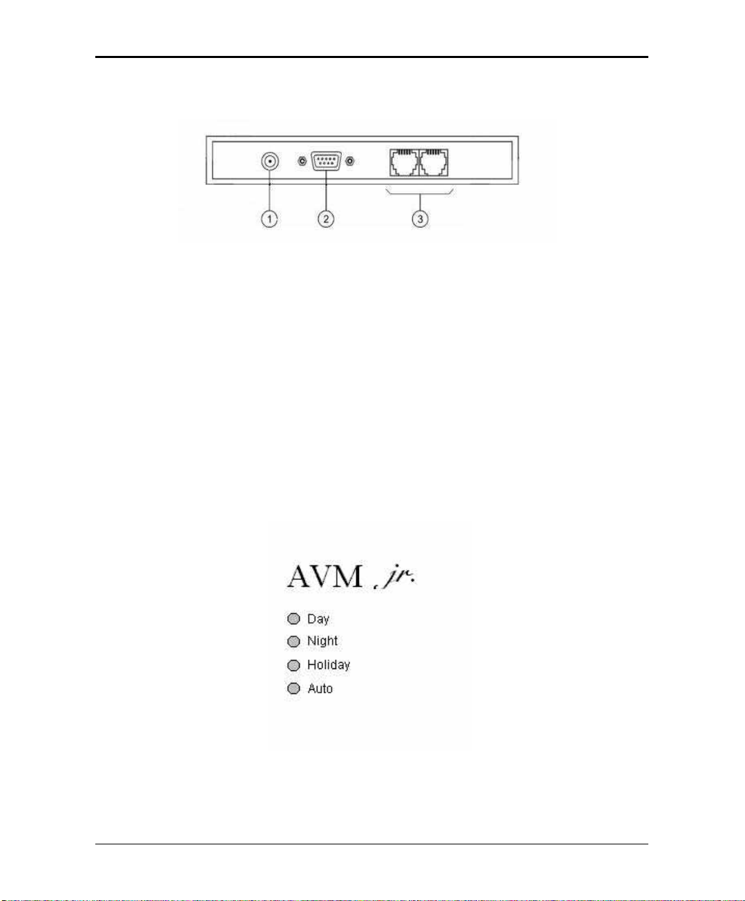
2.2.1 Side Panel
Figure 2-2 Side Panel
The numbered items in the following description correspond to the labels in
Figure 2-2.
1. Power Supply Connector Connects the AVM JR. to the external power supply
2. RS-232 Connector Connects the AVM JR. to the Key System or a PC
3. 2 RJ-11 Sockets Connects the AVM JR. to 2 or 4 Key System
extensions
2.2.2 Front Panel
Figure 2-3 LED's on the Front Panel
Atlas AVM JR. Installation and Programming Manual 2-3
Page 18

Description and Installation
The following table describes the function of the four LED's on the front panel.
STATUS DAY NIGHT HOLIDAY AUTO
Day Mode: Manual On Off Off Off
Night Mode: Manual Off On Off Off
Holiday Mode: Manual Off Off On Off
Day Mode: Auto On Off Off On
Night Mode: Auto Off On Off On
Break Mode: Auto On On Off On
System Error1 Off Flashing Off Off
System Error1 Flashing Flashing Flashing Flashing
System Error1 Flashing Flashing Flashing Off
Automatic Self-Test On On On On
1
Please contact technical support.
2.32.3 InstallationInstallation
The AVM JR. is delivered completely assembled. It is designed for mounting on a
wall close to the KSU.
2.3.1 Unpacking
Before unpacking, inspect the package. If you notice any damage, immediately
report it to technical support.
ä To unpack the AVM JR.:
1. Place the package on a flat surface and open it.
2. Remove the contents of the package and place them on a clean surface.
3. Remove all packing material.
4. Inspect the contents. If you notice any physical damage, immediately
report it to technical support.
2-4 Atlas AVM JR. Installation and Programming Manual
Page 19
2.3.2 Installing the AVM JR.
ä To install the AVM JR.:
1. Mount the unit on a wall close to the KSU by using the drill template to
place the two screws.
2. Connect the RJ-11 connector on one end of the cables to the RJ-11 sockets
on the side panel of the AVM JR.. Connect the other end of the cables to
one or two analog telephone lines on the Main Distribution Frame (MDF)
of the KSU (see Figure 2-4).
Note: Each RJ-11 socket on the side panel of the AVM JR. can support up
to two single line extensions.
Description and Installation
Figure 2-4 Analog Line Connections
Atlas AVM JR. Installation and Programming Manual 2-5
Page 20

Description and Installation
4. On the side of the AVM JR., plug the 9V DC adapter jack into the power
supply connector.
5. Plug the 9V DC adapter into the main power supply outlet to turn the
AVM JR. on. The LED's on the front panel turn on and off one after
another and then the LED indicating the status of the AVM JR. turns on.
6. Connect one end of the RS-232 cable to the AVM JR.’s RS-232
connector and the other end to the RS-232 connector of the SMDR.
- If you are using an SMDR-E unit, you should plug the RS-232 cable
into the port labeled COM 2 on the SMDR.
- If you are using an SMDR-256/64 unit, you should plug the RS-232
cable into the port labeled J1, the lower of the DB-25 connectors on
the card. To do this you will have to use the supplied DB-9 to DB-25
converter.
- If you are using an SMDRU (KDX-500) unit you should plug the RS-
232 cable into the port labeled CN10 (Com 3)
Note: If you are attaching a caller id unit or InnFone call accounting
system to the SMDR along with the voicemail you must remove pin 3
from the DB-9 connector that attaches to the SMDR RS-232 port.
However, please contact technical support before doing this to verify
your application.
- Refer to APPENDIX D for cabling diagrams
7. Set your dip switch settings on the SMDR
- If you are using an SMDR-E you should turn switch one (1) on and
have six (6) off. The rest do not affect the voicemail interface
- If you are using an SMDR-256/64 you should turn switch one (1) on
and have three (3) and six (6) off. The rest do not affect the voicemail
interface.
- If you are using an SMDRU, you do not need to set any DIP switches.
- Refer to APPENDIX D for SMDR switch location.
8. Call each AVM JR. line from any extension and verify the answer. You
should hear the default greeting (system message no. 000. See Appendix C).
9. Program the AVM JR. according to your required applications.
2-6 Atlas AVM JR. Installation and Programming Manual
Page 21
Description and Installation
10. Program the analog station ports you are using as voicemail ports in the
KSU. Refer to APPENDIX E for programming procedures for your
particular system as they vary between systems.
11. Program the voicemail ports into a station hunt group. Refer to APPENDIX
E for programming procedures for your particular system as they vary
between systems.
12. Program the voicemail to ring for incoming calls, either delayed or direct.
Refer to APPENDIX E for programming procedures for your particular
system as they vary between systems.
Figure 2-5 System Installation
2.3.3 Expanding the System
The basic AVM JR. includes two lines and two hours and forty minutes of
recording time. You can expand the AVM JR. to four lines and up to eight hours
of recording time by adding expansion cards.
Atlas AVM JR. Installation and Programming Manual 2-7
Page 22

Description and Installation
2.3.3.1 Expanding to Four Lines
The two-port expansion kit contains:
•
2-port expansion card
•
4-wire connector
•
Two plastic stand-offs
ä To install the expansion card:
1. Disconnect all external cables and connectors.
2. Remove the 9V DC adapter power plug from the main power supply outlet
to turn the AVM JR. off.
3. Open the AVM JR.’s top cover by unscrewing the four screws.
4. Place the two plastic stand-offs into the corresponding holes.
5. Insert the expansion card into the corresponding J6 connector.
6. Connect one end of the 4-wire cable to J5 on the motherboard and the
other end to J5 on the expansion card.
7. Replace the top panel cover and plug the 9V DC adapter into the main
power supply outlet to turn the AVM JR. on.
8. Reconnect all the external cables and connectors to the AVM JR..
9. Connect your two new analog ports to the corresponding connectors on the
AVM JR.
10. Program your two new ports as voicemail ports. Refer to APPENDIX E for
programming procedures for your particular system as they vary between
systems.
11. Program your two new ports in your voicemail station hunt group. Refer to
APPENDIX E for programming procedures for your particular system as
they vary between systems.
AVM JR. automatically detects the two new lines when it is turned on.
2.3.3.2 Expanding Flash Memory
The AVM JR. has two types of expansion memory cards:
•
Two hours and forty minutes card with 2 memory chips
2-8 Atlas AVM JR. Installation and Programming Manual
Page 23

Description and Installation
•
Five hours and twenty minutes card with 4 memory chips
ä To install the memory expansion card:
1. Disconnect all external cables and connectors.
2. Remove the 9V DC adapter power plug from the main power supply outlet
to turn the AVM JR. off.
3. Open the AVM JR.’s top cover by unscrewing the four screws.
4. Insert the memory card into the SIMM connector.
5. Replace the top panel cover and plug the 9V DC adapter into the main
power supply outlet to turn the AVM JR. on.
6. Reconnect all the external cables and connectors to the AVM JR..
AVM JR. automatically detects memory size when it is turned on.
I
Although the memory modules may look like regular PC memory they are
not. Installing regular PC memory may result in damage to the system and void
your warranty.
Atlas AVM JR. Installation and Programming Manual 2-9
Page 24

Description and Installation
2.42.4 SpecificationsSpecifications
DC Power Supply
Line Voltage
DC Leakage Current
On-hook Insulation Resistance between
Line Terminal and
the Ground
Ring Capacitor
On-hook Impedance
Ring Detect
DC Resistance (off-hook)
Impedance (off-hook)
Imbalance Ratio
Return Loss
Current during Break
DTMF Transmission:
Frequency Tolerance
Frequency Level (High Group)
Frequency Level (Low Group)
Inter-digit Pause in Tone Dialing
Fax CNG Tone Detection
9V DC/800 mA
24V to 72V DC
< 10 µA
0V to 100V DC > 5 MΩ
100V to 200V DC > 30 KΩ
500V AC/50 Hz > 20 KΩ
100V AC/25 Hz > 100 KΩ
0.47 µF ± 10%
@ 50V DC, 40V AC/25 Hz > 3000 Ω
27V to 100V AC/16 to 60 Hz
24V to 66V DC @ 20 to 100 mA 100 to 350 Ω
300 to 3400 Hz 500 to 700 Ω
300 to 3400 Hz > 46 db
300 to 3400 Hz > 18 db
< 700 µA
+1.5%
-6 to -8 dBm
-8 to -10 dBm
70 to 80 ms
1100 Hz ± 38 Hz
2-10 Atlas AVM JR. Installation and Programming Manual
Page 25

3. DTMF PROGRAMMING
You can program the AVM JR. by:
•
Telephone using DTMF tones
•
Computer using the Voicemail Utility Program (see Section 4)
This section describes programming the AVM JR. using DTMF tones.
Note: You will hear a confirmation tone every time you enter a programming
command.
3.13.1 Entering andEntering and Exiting the Programming Mode Exiting the Programming Mode
The AVM JR. does not handle calls when in the programming mode.
ä To enter the programming mode:
1. Connect a single line extension to the AVM JR.. (This should have been
done during the installation)
2. Call the single line extension from any other extension on the system.
3. Wait until the AVM JR. answers and plays the opening menu. Then dial
*900.
Note: If you are calling from a system extension that has a mailbox set up for
it you will first have to dial the mailbox password and then from the
mailbox menu dial “9” to get to the main greeting. You can then dial
“*900”
4. Dial the System Administrator’s password (the default password is 1234)
to enter the programming mode.
ä To exit the programming mode:
•
Dial *900.
–or–
Do not dial for one minute.
Atlas AVM JR. Installation and Programming Manual 3-1
Page 26

DTMF Programming
Note: If you exited the programming mode by dialing *900, the AVM JR. plays the
opening menu. You can then test the changes made to the system.
3.23.2 First Time Programming ChecklistFirst Time Programming Checklist
1. Call from a system extension to the AVM JR.. You will hear the default
message (system message 000 - see Appendix C).
2. Dial *900 and the administrator password (default: 1234) to enter the
programming mode.
3. Set the KSU parameters (see Sections 3.3 and 6) to ensure the proper operation
of the AVM JR. with your KSU.
Note: These parameters are set by the factory for a 2-digit system all flash
times and message light parameters should not have to be changed.
4. Set the AVM JR’s real-time clock (see Section 3.4).
5. Set the system schedule (see Section 3.5).
6. Create mailboxes (see Section 3.6.1).
7. Define a notification type for each mailbox (see Section 3.6.3).
8. Define notification parameters (i.e., message light on and message light off
and interval between ring notification in Section 3.6.3.) Message light
parameters are set from the factory.
9. Record (see Section 3.7.1) and program (see Section 3.7.2) script menus for
the Automated Attendant. Make sure you define the mailboxes before
building Automated Attendant script menus.
Important: Make sure you record the Day Opening script (script 00)
before using the AVM JR. for the first time.
3.33.3 Defining KSU ParametersDefining KSU Parameters
To integrate the AVM JR. with your KSU, apply the following parameters to the
AVM JR.. To obtain your current KSU parameters, check your Programming
Manual or the current programming setup.
Table 3-1 presents the commands you must enter to apply the KSU parameters to
the AVM JR..
3-2 Atlas AVM JR. Installation and Programming Manual
Page 27

DTMF Programming
1 for port 1
2
1 for port 3
Table 3-1 PBX Parameter Commands
OPERATION COMMAND DEFAULT
Extension Size
Cut off time for
continuous call
progress tone
detection
*300 + X
Where X is a digit 1-4
You can only change this parameter if mailboxes
and/or legal extensions have not yet been defined.
*301 + X
Where
X= cut off time in seconds (0-9)
2
6 seconds
Number of rings
before the line is
answered
Time to wait for
No-Answer
Legal KSU
Extensions
Resetting a group
*310 + X +Y
Where
X is the port number (1-4)
Y is the number of rings (1-9)
Note: this field will only be in affect if the SMDI
integration is not working. To program ringing to
voicemail see APPENDIX E.
*311 + XX
Where XX is 00-99 seconds.
This code is applicable only when supervised
transfer is selected
*320 + Y + First Ext. + Last Ext. + #
where Y is a group number (0-9).
Example: *320 0 330 350 #
*320 1 355 375 #
You can define up to 10 groups of legal extensions.
If a caller dials an extension by direct dialing (code
170), AVM JR. checks if the extension is legal. If the
extension is not legal, AVM JR. does not transfer the
call.
*320 + Y + 000 + 000 + # (the two groups of zeros
can be 2, 3, or 4 digits long, according to the
extension size)
1 for port
1 for port 4
20 seconds
None
None
Resetting all
groups
Operator ID Code
Atlas AVM JR. Installation and Programming Manual 3-3
*320 + #
*330 + X
where X is a digit 0-9
When the caller dials this digit during any script
message, the call is transferred to the operator.
None
0
Page 28

DTMF Programming
OPERATION COMMAND DEFAULT
Programmable
code for retrieving
messages
Disconnect Code
Clear Disconnect
Code
External Access
Code
Clear External
Access Code
Pause before and
after external
access code
*331 + X
Where X is a digit 0-9
When the caller dials this digit at the no answer or
busy greeting for their mailbox the system will
prompt them for their password
*333 + Code1 + #
The AVM JR terminates the call when it receives the
disconnect code. The code can include up to four
digits. Legal values for this code can be any
combination of 0-9, *, # and A-D
*333 + #
*340 + X
where X is the external access code (0-9).
This code is applicable for external notification.
*340 + #
*341 + X
Where X is the length of the pause in seconds (0-9)
9
###
9
2 seconds
Transfer mode for
all extensions
3-4 Atlas AVM JR. Installation and Programming Manual
*350 + X + Y
X = 1; All Extensions except the operator
X = 2; Operator extension only
Y = 0; Non Supervised
Y = 1; Supervised Mode
Y = 2; Semi Supervised Mode
NonSupervised
Page 29

DTMF Programming
OPERATION COMMAND DEFAULT
Day Operator,
Night Operator,
Fax and
Supervisor’s
Extension numbers
*360 + X + YYYY + #
where:
X = 1; Day operator
X = 2; Night operator
X = 3; Fax extension
X = 4; Supervisor extension
One mailbox can be defined as Supervisor. When
the storage memory reaches 80% of its capacity, a
message is sent to this mailbox indicating the
situation.
YYYY = Corresponding extension number
0
0
-
-
Delete the
extension
assignments
Volume level
Flash-1
Flash-2 Flash-2 is fixed at 1200 ms.
Busy, Disconnect
and DTMF Off/On
time
*360 + X + #
Where:
X = 1; Day operator
X = 2; Night operator
X = 3; Fax extension
X = 4; Supervisor extension
*369 + X
Where:
X = volume level (0-9), 9 = Loudest
*370 + XXX
where XXX is a 3-digit number (000-980) in
increments of 20 ms.
Example: *370 300 sets Flash-1 to 300 ms
Flash-2 is used in some KSU’s for Recall from NoAnswer or Busy Codes.
*371 + X + YYY
where:
X = 1; busy off (100-980 ms)
X = 2; busy on (100-980 ms)
X = 3; disconnect off (100-980 ms)
X = 4; disconnect on (100-980 ms)
X = *; DTMF off (000-980 ms)
X = #; DTMF on (000-980 ms)
YYY = Cadence in milliseconds in increments of 20
milliseconds
5
600 ms
1200 ms
500 ms
500 ms
240 ms
240 ms
200 ms
60 ms
Atlas AVM JR. Installation and Programming Manual 3-5
Page 30

DTMF Programming
he sensitivity level, the higher
OPERATION COMMAND DEFAULT
Busy Signal
Cadence Check
*375 + XXXX + #
Where XXXX is a busy extension number. Checks
the busy signal by dialing the busy extension number
and playing the busy cadence values.
Voice and DTMF
Sensitivity
*376 + X + Y
X = 1; Voice sensitivity level
X = 2; DTMF sensitivity level
Y = Sensitivity level (0-9)
The volume at which the AVM JR detects voice
when the called extension answers or the volume
level at which the unit detects DTMF throughout it’s
operation.
Note: The higher t
the sensitivity to voice or DTMF.
In order to activate the new selection, a new call
must be initiated
Automatic Gain
Control (AGC)
*377 + X
X = 0 AGC disabled
X = 1 AGC enabled
When enabled, AVM JR will adjust the incoming
messages volume to a set volume level.
In order to activate the new selection, a new call
must be initiated
5
5
Enabled
DTMF amplitude
*379 + X
5
Where X = volume level (0-9), 9 = Loudest
Procedural codes
sent to the PBX in
order to perform a
specific task
*380 + X + CODE1 + #
X = 1; LED 1 notification code
X = 2; LED 2 notification code
X = 3; LED notification off code
X = 4; Transfer code
X = 5; Recall from Busy
X = 6; Recall from No Answer
743X
740X
Flash 1 + Ext
Flash 1
Flash 1
CODE1 = Respective PBX code
3-6 Atlas AVM JR. Installation and Programming Manual
Page 31

DTMF Programming
OPERATION COMMAND DEFAULT
Delete a specific
procedural code
Answer number of
samples
1
Refers to Key System codes. Each code contains digits 0-9, *, #, Flash-1,
*380 + X + #
X = 1; LED 1 notification code
X = 2; LED 2 notification code
X = 3; LED notification off code
X = 4; Transfer code
X = 5; Recall from Busy
X = 6; Recall from No Answer
*386 + X
Where:
X = number of samples (0-9)
5
Flash-2, Pause and Extension Number.
Note: The PBX codes for Message Light On and Message Light Off can also
include A-D.
When entering a code, dial:
*0 for extension
*1 for pause
*2 for Flash-1
*3 for Flash-2
*4 for #
*5 for A
*6 for B
*7 for C
*8 for D
** for *
Atlas AVM JR. Installation and Programming Manual 3-7
Page 32

DTMF Programming
3.43.4 Setting the Time and DateSetting the Time and Date
Table 3-2 presents commands used to set the AVM JR. clock and calendar.
Table 3-2 Commands to Set the AVM JR. Clock and Calendar
OPERATION COMMAND
Setting the time and day of the week
Setting the date
Listening to the system time
*420 + HH + MM
where
HH = hour (00-23)
MM = minutes (00-59)
Example: *420 15 25 stands for 3:25 P.M.
*430 + DD + MM + YY
where
DD = date of the month (01-31)
MM = month (01-12)
YY = year (00-99)
Example: *430 15 03 97
March 15, 1997
Note: 00 represents Year 2000.
*440
The system announces the date and time.
3.53.5 Programming the Operational ModeProgramming the Operational Mode
The AVM JR. can operate in Day, Night, Break, or Holiday mode. If the AVM
JR. is in the Auto mode, it automatically changes modes according to programmed
weekly working hours.
3-8 Atlas AVM JR. Installation and Programming Manual
Page 33

DTMF Programming
Table 3-3 Programming the Operational Modes
OPERATION COMMAND
Selecting an Operational
Mode
Selecting time stamp format
(Applicable to English only)
Setting the Working Time
(for Auto mode only)
*400 + X
where X stands for the operational mode.
Day mode = 0 (default mode)
Night mode = 1
Holiday mode = 2
Auto mode = 3
Break mode = 4
*410 + X
where
X = 0 means the time stamp is in 12-hour format (default)
X = 1 means the time stamp is in 24-hour format
*450 + D + HH MM + HH MM
where
D is the day of the week (1-7)1
First HH MM = start of work time
Second HH MM = end of work time
Repeat for all days of the week.
Example: *450 1 08 30 1700 means that the AVM JR.
will play the Day mode opening greeting (script
message 00) on Monday from 8:30 until 17:00.
It will play the Night mode opening greeting
(script message 10) the rest of the time.
Note: Day 1 is Monday day 2 is Tuesday day 3 is
Wednesday day 4 is Thursday day 5 is Friday
day 6 is Saturday and day 7 is Sunday.
Atlas AVM JR. Installation and Programming Manual 3-9
Page 34

DTMF Programming
The AVM JR will play the Holiday mode
OPERATION COMMAND
Setting the Break Time
(for Auto mode only)
Entering annual holiday
dates
(For Auto mode only)
*460 + D + HH MM + HH MM
where
D is the day of the week (1-7)1
First HH MM = start of break time
Second HH MM = end of break time
Repeat for all days of the week.
Example 1: *460 1 13 15 14 30
AVM JR. will play the Break mode opening
greeting (script message 15) on Monday, from
13:15 until 14:30.
Note: Day 1 is Monday day 2 is Tuesday day 3 is
Wednesday day 4 is Thursday day 5 is Friday
day 6 is Saturday and day 7 is Sunday.
*470 + DD + MM + hh:mm + hh:mm
Where:
DD = Day of month (01-31)
MM = Month (01-12)
Hh:mm = Start time; Hour and minutes in 24 hour format
Hh:mm = End time; Hour and minutes in 24 hour format
Repeat for multiple days
Example 1: *470 02 12 08 15 23 45
Delete all holidays on a
specific date
Delete all holidays on a
specific month
Delete all holidays
3-10 Atlas AVM JR. Installation and Programming Manual
opening greeting on December 2nd, from 8:15
until 11:45.
*470 + DD + MM #
Where:
DD = Day of month (01-31)
MM = month (01-12)
*470 + ** + MM + #
Where:
MM = month (01-12)
*470 + #
Page 35

DTMF Programming
AVM JR will activate the external notification
OPERATION COMMAND
External Notification Active
Time
*490 + hh:mm + hh:mm
Where:
hh:mm = Start time; Hour and minutes in 24 hour format
hh:mm = End Time; Hour and minutes in 24 hour format
Example 1: *490 09 00 20 00
between 9 am to 8 pm.
3.63.6 Programming the Voice MailProgramming the Voice Mail
3.6.1 Creating Mailboxes
You can define up to 128 mailboxes. The mailbox number and its extension
number are identical. Make sure that the number of digits in the mailbox number
conforms to the number of digits in an extension (*300).
You can also create a virtual mailbox for a user who does not have an extension.
When a caller dials a virtual mailbox number on the Automated Attendant menu,
the call is immediately transferred to the Do Not Disturb menu and the caller is
given the option to leave a message.
You may use the external notification features for the virtual mailboxes. Do not
select internal notification because virtual mailboxes do not have extensions to
light message waiting lights on.
You can assign a mailbox for announcing messages without the ability to record
incoming messages. This mailbox is called an Announcer mailbox. All mailboxes
can be changed from regular mailboxes to an announcer and vice versa at any time.
Atlas AVM JR. Installation and Programming Manual 3-11
Page 36

DTMF Programming
OPERATION COMMAND
Table 3-4 Commands to Create Mailboxes
Creating a range of mailboxes
Creating one mailbox
Selecting an announcer mailbox
Deleting a mailbox
Creating a range of virtual mailboxes
Creating one virtual mailbox
Defining whether to play or skip the
time and date stamp during message
playback for a range of mailboxes
real or virtual.
Defining whether to play or skip the
time and date stamp during message
playback for one mailbox real or
virtual
*500 + First Mailbox + Last Mailbox + #
*501 + Mailbox Number + #
*502 + XXXX + Y + #
Where:
XXXX = existing mailbox number
Y = 0; Regular mailbox (default)
Y = 1; Announcer mailbox
*510 + Mailbox Number + #
Make sure to remove any transfer to the deleted
mailbox from the Automated Attendant scripts.
*520 + First Mailbox + Last Mailbox + #
*521 + Mailbox Number + #
*530 + First Mailbox + Last Mailbox + B + #
where
B = 0; Play the date and time stamp (default)
B = 1; Skip the date and time stamp
*531 + Mailbox Number + B + #
where
B = 0; Play the date and time stamp (default)
B = 1; Skip the date and time stamp
3.6.2 Creating Mailbox Groups
You can create up to four mailbox groups for distributing messages. Each mailbox
group can contain up to twenty mailboxes. The group numbers are by default 000,
001, 002 and 003. Group 099 consists of all mailboxes (real and virtual).
You can select a different number for the first digit of the mailbox groups using
code *545. Make sure that you select a number that does not interfere with
your KSU’s numbering plan.
3-12 Atlas AVM JR. Installation and Programming Manual
Page 37

DTMF Programming
Table 3-5 Commands to Create Mailbox Groups
OPERATION COMMAND
Adding a mailbox to a group
Changing the number of the first
digit in the mailbox groups
Deleting a mailbox from a group
Resetting a group
*540 + Group Number + Mailbox Number + #
Note: You must define the mailbox before adding
it to a group.
*545 + X
where X is the first digit of the mailbox groups.
Default is 0.
*550 + Group Number + Mailbox Number + #
*560 + Group Number + #
Note: Resetting a group deletes all the mailboxes
within that group.
3.6.3 Notification
AVM JR. notifies the mailbox owner of new messages in different ways according
to the system configuration. Notification may be local or remote.
Notification is always done on port two.
Local Notification
You can select one of the following options:
•
None. The notification feature is disabled.
•
Message Light On. The AVM JR. signals the Key System that a mailbox has
received the first message. The Key System then turns on the message light of
the telephone extension. If the Message Light Off code is programmed, the
code is sent to the KSU after the mailbox owner retrieves all his new
messages.
•
Rings. The AVM JR. rings the notified extension for a programmed time
period (code *730). When the mailbox owner answers, the AVM JR. prompts
him to enter his password. After entering the password, the mailbox owner
may retrieve his messages. If the mailbox owner does not answer, the AVM
JR. tries again at programmed intervals (code *720). The AVM JR. stops
sending Ring notifications after the mailbox owner retrieves all his new
messages or the maximum number of retries has been made (code *750).
Atlas AVM JR. Installation and Programming Manual 3-13
Page 38

DTMF Programming
Remote Notification
The mailbox owner may choose to be notified at a remote location (i.e., his mobile
or home telephone number) by entering a remote telephone number of up to 20
digits. You can use any combination of *, #, A-D, 0-9, and Pause (*1) when
setting the remote notification telephone number.
After remote notification is enabled, the AVM JR. will dial the remote telephone
number and notify the mailbox owner of any new messages. After entering the
password, the mailbox owner can retrieve his messages. The duration of remote
notification rings is programmed using code *730.
The AVM JR. stops sending Ring notifications after the mailbox owner retrieves
all his new messages or the maximum number of retries has been made (code
*750). The mailbox owner must obtain permission from the System Administrator
to enable remote notification. The System Administrator must use code *710 or
*711 to grant permission.
When permission has been granted and the mailbox owner enables remote
notification, the AVM JR. first dials the external access digit (programmed using
code *340) and then dials the mailbox owner’s remote telephone number.
Note: Make sure that you enter the remote telephone number before enabling
remote notification.
Notification is always done on port two.
3.6.3.1 Setting Notification for Mailboxes
Notes:
1. Virtual mailboxes do not have extensions and may not be configured for
internal notification.
2. When remote notification for a mailbox is enabled, local notification for that
mailbox is automatically disabled.
3-14 Atlas AVM JR. Installation and Programming Manual
Page 39

DTMF Programming
Table 3-6 Commands to Program Notification for Mailboxes
OPERATION COMMAND
Setting local notification for a range
of real mailboxes
Setting local notification for one real
mailbox
Permitting remote notification for a
range of mailboxes real or virtual
Permitting remote notification for
one mailbox real or virtual
Message Notification Interval
Ring Notification Duration
*700 +First Mailbox + Last Mailbox + X+#
where
X = 0 means notification is disabled
X = 1 means Message Light On 1 is selected
X = 2 means Message Light On 2 is selected
X = 4 means Rings is selected
*701 + Mailbox + X + #
where X is defined as above
*710 + First Mailbox + Last Mailbox + Y + #
where
Y = 0 means remote notification is not permitted
Y = 1 means remote notification is permitted
*711 + Mailbox + Y + #
where Y is defined as above
*720 + XX
where XX is a 2 digit number in minutes.
Default is 30 minutes.
This timer is how often the system checks to see if a
mailbox has a new message waiting to notify the
mailbox owner.
*730 + X
where
X = 0 stands for short time for rings (default)
X = 1 stands for long time for rings
Number of Ring Notification retries
Activate the LED notification
Atlas AVM JR. Installation and Programming Manual 3-15
*750 + XX
where XX refers to the number of ring notification
attempts.
Default is 05.
*760 + X
Where
X = 0 for the 1st new message (Default)
X = 1 for every new message
Page 40

DTMF Programming
3.73.7 Programming the Automated Attendant Script MenuProgramming the Automated Attendant Script Menu
The AVM JR. supports up to 21 script messages (00-20) for building the
Automated Attendant menu. The AVM JR. also supports another five script
messages (21-25) for Busy, No Answer and Do Not Disturb menus (see Section
3.7.5).
The following numbers are dedicated to specific script messages:
•
Script message number 00 to the Day Mode Opening Menu
•
Script message number 10 to the Night Mode Opening Menu
•
Script message number 15 to the Break Time Opening Menu
•
Script message number 20 to the Holiday Mode Opening Menu
The rest of the script messages (01-09, 11-14 and 16-19) may be used in all modes
without limitations.
Each script message has three parts:
•
Script message number
•
Recorded announcement
•
Programming that indicates the action to be taken when a caller dials one digit
(0-9) or dials nothing during an announcement
3.7.1 Recording Script Messages
Table 3-7 describes how to record script messages.
Table 3-7 Commands for Recording Script Messages
OPERATION COMMAND
Recording a script message
Playback a script message
Deleting a script message
Note: XX is script message 00-25.
IMPORTANT: You must record script message 00 for AVM JR. to operate properly.
3-16 Atlas AVM JR. Installation and Programming Manual
*100 + XX + Beep + Record + #
*101 + XX
*102 + XX
Page 41

DTMF Programming
3.7.2 Programming Script Messages
You can program each script message separately. The programming command
format for script messages is:
* + Command Code + XX + B + YY + #
Where:
•
Command Code defines the action that should be taken when B is pressed
during playback of script message XX.
•
XX refers to one of 25 script message numbers.
•
B refers to the digit dialed by the caller during playback of script message XX
or at the end of the message. B can be 0-9 or * (for end of message).
•
YY refers to the destination, which can be an extension, mailbox or another
script message.
IMPORTANT: Do not define the Operator ID digit on script messages.
Table 3-1 describes how to define the operator ID digit which is
then automatically reserved on all script messages.
The command codes used to build the Automated Attendant Script Menu are
presented on the following pages. You can program one of the following actions
for each script message:
•
Play another script message
•
Return to the opening menu
•
Transfer the call to an extension
•
Transfer the call to the operator
•
Transfer the call to a mailbox
•
Disconnect the line
•
Leave a message in a mailbox
•
Retrieve messages from a mailbox
•
Directly dial an extension
•
Directly transfer a call to a mailbox
Atlas AVM JR. Installation and Programming Manual 3-17
Page 42

DTMF Programming
•
Place a call on hold
•
Blind Transfer to the busy extension
Technicians and System Administrators should program the script messages
according to the application.
3.7.2.1 Programming the EOM Timeout for Each Script
Sets the EOM timeout period for each script individually. This is the amount of
time to wait after playing the script message before processing the EOM option.
Command: *105 + XX + Y + #
Where:
XX = Script number
Y = Timeout in seconds
Example 1: *105 05 6 #
The AVM JR sets the EOM timeout to 6 seconds for script message 05.
3.7.2.2 Play Another Script Message
Build sub-menus by transferring the caller from one script message to another
when the caller dials a certain digit.
Command: *110 + XX + B + YY + #
Example: *110 00 3 02 #
The AVM JR. plays script message 02 when “3” is dialed during
playback of script message 00.
Note: Make sure to record any script message you use.
3.7.2.3 Select Opening Script
Selects the opening script message for individual ports. This allows you to have
different greetings for different ports.
3-18 Atlas AVM JR. Installation and Programming Manual
Page 43

DTMF Programming
Command: *112 + XX + YY + Z + #
Where:
XX = Default script number 00,10,15 or 20
YY = Replacement script number 00-20
Z = Port Number 1-4
3.7.2.4 Return to the Opening Menu
Transfers the caller to the opening main menu. Used mainly by Busy and NoAnswer script messages (21-24), where the caller is given the option to return to
the main menu. The caller is transferred to script 00 in Day mode, script 10 in
Night mode, script 15 in Break mode and script 20 in Holiday mode.
Command: *115 + XX + B #
Example: *115 21 5 #
The AVM JR. plays the opening menu when “5” is dialed during
playback of script message 21.
3.7.2.5 Transfer the Call to an Extension
Transfers the caller to an extension or department (hunt group).
The designated extension number may contain up to 4 digits and does not have to
be in the range of legal extensions.
Command: *120 + XX + B + extension number + #
Example 1: *120 05 3 123#
The AVM JR. transfers the call to extension 123 when “3” is dialed
during playback of script message 05.
Example 2: *120 00 * 782 #
The AVM JR. transfers the call to hunt group 2 at the end of script
message 00.
Atlas AVM JR. Installation and Programming Manual 3-19
Page 44

DTMF Programming
3.7.2.6 Transfer the Call to the Operator at the End of the Script
Message (If nothing is dialed by the caller)
Transfers the call to the operator at the end of the script message. The operator
extension is defined in Table 3-1 (codes *360 and *361).
The AVM JR. transfers the call in supervised, semi-supervised or non-supervised
mode depending on code *351 (see Section 3.7.5).
Command: *125 + XX + #
Example: *125 00 #.
The AVM JR. transfers the call to the operator at the end of script
message 00.
3.7.2.7 Transfer the Call to a Mailbox
Transfers the caller to a specific mailbox number. The mailbox must be defined
(see Section 3.6.1).
Command: *130 + XX + B+ Mailbox number + #
Example: *130 01 5 152 #
Transfers the call to mailbox 152 when “5” is dialed during playback
of script message 01.
3.7.2.8 Disconnect the Line
Disconnects the call at the end of the script message or if the caller dialed the
disconnect digit during playback.
This command may or may not include the following system message:
“Thank you and good-bye.”
Command: *140 + XX + *+Z+#
Where:
Z = 0; means disconnect the line with no message.
Z = 1; means disconnect the line with the above system message
3-20 Atlas AVM JR. Installation and Programming Manual
Page 45

DTMF Programming
Example: *140 10 * 1 #
The AVM JR. plays the disconnection message and then disconnects
the call at the end of script message 10.
3.7.2.9 Leave a Message in a Mailbox
Initiates the procedure for leaving a message in a mailbox. This can be used either
during a greeting or in script messages 21, 23 and 25. When used during a
greeting the user will be able to dial B+XX and then press TRF to send the caller
directly into a mailbox. When used during script messages 21, 23 and 25 the
system will put the caller into the mailbox that the call was for.
Command: *150 + XX + B + #
Example: *150 00 8 #
The AVM JR. asks for a mailbox number when “8” is dialed during
playback of script message 00. After dialing the requested mailbox
number, the caller hears the mailbox greeting and can leave a message.
3.7.2.10 Retrieve Messages from a Mailbox
Initiates the procedure for retrieving messages from a mailbox.
Command: *160 + XX + B + #
Example: *160 00 9 #
The AVM JR. asks for a mailbox number and password when “9” is
dialed during playback of script message 00. After dialing the
requested mailbox number and password, the mailbox owner can
retrieve his messages and access the user menu to record a personal
greeting, change his password, etc.
3.7.2.11 Directly Dial an Extension
Enables the caller to dial an extension directly by programming the first digit of
the extension. When a caller dials the first digit of an extension during playback
of a script message, the AVM JR. stops the message and waits for the rest of the
digits of the extension. The number of digits in an extension is defined by code
*300 in Table 3-1. You can enter up to four different digits.
Atlas AVM JR. Installation and Programming Manual 3-21
Page 46

DTMF Programming
Note: You must program this option to enable the voicemail to transfer calls to
extensions in the system.
Command: *170 + XX + first digit(s) + #
Example 1: *170 00 2 #
The AVM JR. waits for the rest of the extension number when “2” is
dialed during playback of script message 00. After the caller dials the
rest of the extension number, the AVM JR. transfers the call to the
extension.
Example 2: *170 00 2 4 #
Same as Example 1, except the extension number starts with 2 or 4
(for extension numbers 2XX and 4XX).
3.7.2.12 Directly Transfer a Call to a Mailbox
Transfers the call directly to a mailbox number on the opening greeting script
message only. This feature is similar to directly dialing an extension, except the
call is transferred directly to a mailbox. This feature is used to place a caller
directly into the mailbox of someone who may be out of the office or unavailable
to take the call. You can enter up to four different digits.
Note: Do not confuse this with *150. This option would be used (for example) if
you had a live operator answering and transferring calls and then asking the
caller if they want to leave a message.
Note: This option will not work if *170 is programmed for the same digit entry in
the same script message.
Command: *175 + XX + first digit(s) + #
Example 1: *175 00 2 #
The AVM JR. waits for the rest of the mailbox number when “2” is
dialed during playback of script message 00. After the caller dials the
rest of the mailbox number, the AVM JR. transfers the call to the
mailbox.
Example 2: *175 00 2 4 #
Same as Example 1, except the mailbox number starts with 2 or 4.
3-22 Atlas AVM JR. Installation and Programming Manual
Page 47

DTMF Programming
3.7.2.13 Place a Call on Hold
Gives the caller the option to remain on hold. Valid only for script messages 2122, which are reserved for the extension Busy menus.
Command: *180 + XX + B +#
Example: *180 21 3 #
The AVM JR. places the call on hold for 10 seconds before trying to
transfer the call again when “3” is dialed during playback of script
message 21.
3.7.2.14 Blind Transfer to a Busy Extension
Transfers a call in blind mode to a busy extension. Valid only for script messages
21-22, which are reserved for the extension’s Busy menus.
Command: *185 + XX + B + #
Example: *185 21 5 #
The AVM JR. immediately tries to transfer the call again when “5” is
dialed during playback of script message 21.
Note: Both Place a Call on Hold and Blind Transfer to a Busy Extension are used
to transfer calls to a busy extension. Place a Call on Hold retries every 10
seconds to transfer the call until the extension is available. Blind Transfer
to a Busy Extension transfers the call immediately and unconditionally to
the busy extension.
3.7.3 Directory Listing Programming
The directory-listing feature (Dial By Name) allows calls to be transferred to
proper extensions based on recorded names and codes of mailbox owners. The
directory listing parameters are set through the commands explained in the
following paragraphs
3.7.3.1 Directory listing format
Changes the format of the directory listing. The AVM JR supports two directorylisting formats.
Atlas AVM JR. Installation and Programming Manual 3-23
Page 48

DTMF Programming
Command: *011 + X
Where:
X = 0; List according to the last name (Default)
X = 1; List according to the first name
3.7.3.2 Transfer to the directory listing
Transfer the call to the directory listing.
Command: *111 + XX + B + #
Where:
XX = Script Number
Example: *111 00 5 #
Play the directory listing when “5” is dialed during playback of script message
00.
3.7.4 Reset Script Message Programming to Default
Resets a complete script message or only one entry (see Section 3.7.2) Does not
delete the recorded script message.
Resetting a Complete Script Message
Command: *190 + XX + #
Example: *190 03 #
Resets script message 03 to its default values.
Resetting One Entry in a Script Message
Command: *190 + XX + B + #
Example: *190 02 5 #
Resets entry 5 in script message 02 to its default value.
3-24 Atlas AVM JR. Installation and Programming Manual
Page 49

DTMF Programming
Default Values
•
0-9. If a caller dials a digit that has not been programmed (or set to default)
during playback of a script message, the AVM JR. plays “This entry is not
supported” and repeats the script message.
•
If the caller dials the Operator ID code, the call is forwarded to the operator
extension regardless of script message programming.
•
At the end of a script message. If the caller does not dial a number during
playback of a script message, AVM JR. disconnects the call at the end of the
message, unless otherwise programmed.
3.7.5 Supervised, Semi-Supervised and Non-Supervised Transfers
Transfer to an extension may be supervised, semi-supervised or non-supervised.
In the supervised mode, the AVM JR. checks for Busy and No-Answer conditions.
In the semi-supervised mode, the AVM JR. only checks for a Busy condition.
In the non-supervised mode, the AVM JR. transfers the call to the extension
without checking for a Busy or No-Answer condition.
The AVM JR is configured to detect Answer, Busy and Do Not Disturb conditions
by recognizing and analyzing the Call Progress tones sent by the KSU.
The AVM JR. distinguishes between two types of transfers:
•
Transfer to operator
•
Transfer to the rest of the extensions
Table 3-8 explains how to program supervised, semi-supervised and
non-supervised transfers to the operator and to the rest of the extensions.
Atlas AVM JR. Installation and Programming Manual 3-25
Page 50

DTMF Programming
Table 3-8 Commands to Program the Transfer Modes
OPERATION COMMAND DEFAULT
Transfer mode to all
extensions
*350 + X + Y
where
X = 1; All extensions except the operator
X = 2; Operator extension only
Y = 0; Non Supervised
Y = 1; Supervised Mode
Y = 2; Semi Supervised Mode
3.7.5.1 Detecting a Busy Extension
If the AVM JR. detects a busy extension, it performs a Recall-from-Busy and by
default plays system message 96 (if the extension has a mailbox) or 103 (if the
extension does not have a mailbox). Refer to Section 3.7.5.3 for information on
changing the default system messages.
3.7.5.2 Detecting a No Answer from an Extension
If the AVM JR. does not detect an answer from the extension, it performs a Recallfrom-No-Answer and by default plays system message 97 (if the extension has a
mailbox) or 104 (if it does not have a mailbox). Refer to Section 3.7.5.3 for
information on changing the default system messages.
Non Supervised
3.7.5.3 Changing the Busy and No Answer Menus
System messages 96, 97, 103, and 104 are default messages. The System
Administrator can replace the system messages with script messages as follows:
•
System message 96 (Busy and the extension has a mailbox) is replaced by
script message 21.
•
System message 103 (Busy and the extension does not have a mailbox) is
replaced by script message 22.
•
System message 97 (No-Answer and the extension has a mailbox) is replaced
by script message 23.
•
System message 104 (No-Answer and the extension does not have a mailbox)
is replaced by script message 24.
3-26 Atlas AVM JR. Installation and Programming Manual
Page 51

DTMF Programming
For instructions on programming the above script messages, see Section 3.7.2. For
instructions on recording the script messages, see Section 3.7.1.
3.7.5.4 Do Not Disturb
Using the user menu, a mailbox owner can activate the Do Not Disturb mode.
When a caller dials a Do Not Disturb extension, the AVM JR. plays system
message 121 and does not transfer the call to the extension. The System
Administrator can replace this message with script message 25.
3.83.8 Additional FeaturesAdditional Features
3.8.1 Changing Passwords
The AVM JR. uses three types of passwords:
•
System Administrator’s password
•
Operator’s password
•
Mailbox owner’s password (see Section 5.2.2)
A password always contains four digits (0-9). The default for all three types of
passwords is 1234.
3.8.1.1 Changing the System Administrator’s Password
The System Administrator can change his password by dialing code *900 to enter
the programming mode, dialing the current password and then dialing:
*600 + XXXX
Where XXXX is the new 4-digit password. Use digits 0-9 only. Do not dial * and
#.
Note: The System Administrator’s password cannot be disabled.
Atlas AVM JR. Installation and Programming Manual 3-27
Page 52

DTMF Programming
3.8.1.2 Changing the Operator’s Password
The System Administrator can change the operator’s password by dialing code
*900 to enter the programming mode, dialing the System Administrator’s
password and then dialing:
*601 + XXXX
Where XXXX is the new 4-digit password. Use digits 0-9 only. Do not dial * and
#.
To disable the operator’s password, enter “0000”.
3.8.1.3 Resetting the Mailbox Password
The System Administrator can reset a mailbox password to its default (1234) by
dialing code *900 to enter the programming mode, dialing the System
Administrator’s password and then dialing:
*570 + XXXX + #
Where XXXX is the mailbox number.
3.8.2 Activate Force Reorganize
The force reorganize option automatically reorganizes and optimizes the data
stored in the AVM JR.
The system administrator can activate the Force Reorganize option by calling the
AVM JR and, during the opening greeting, dialing
*900 + Password + *610
3.8.3 Changing to/from Day Light Saving Time
The operator can change to/from Day Light Saving time by calling the AVM JR
and, during the opening greeting, dialing:
*7 + XXXX + Y
Where:
XXXX refers to the operator’s password.
3-28 Atlas AVM JR. Installation and Programming Manual
Page 53

DTMF Programming
This password can be disabled. See Section 3.8.1.2.
Y = 0; Reduce the time by one hour
Y = 1; Increase the time by one hour
3.8.4 Changing the Operational Mode
The operator can change the operational mode by calling the AVM JR. and, during
the opening greeting, dialing:
*8 + XXXX + Y
Where:
XXXX refers to the operator’s password.
This password can be disabled. See Section 3.8.1.2.
Y = 0; Day Mode
Y = 1; Night Mode
Y = 2; Holiday Mode
Y = 3; Auto Mode
Y = 4; Break Mode
3.8.5 Playing a System Message
You can listen to any system message by dialing:
*690 + 0 + XXX
Where:
XXX is the message number
See Appendix C for a list of system messages.
3.8.6 Listening to the Software Version Number
To hear the AVM JR.’s software version number, dial *680.
3.8.7 Listening to the System Time and Date
To hear the current AVM JR. date and time, dial *440.
Atlas AVM JR. Installation and Programming Manual 3-29
Page 54

DTMF Programming
3.8.8 Resetting the System
The System Administrator can reset the AVM JR. to its factory default settings by
dialing:
*654 + * + XXXX + #
Where XXX is the System Administrator’s password.
3.8.9 Adjusting Recording Length
The System Administrator can select the length of the recorded messages in the
AVM JR. The selected length of message (in minutes) will effect all recorded
messages. The types of recorded messages that are effected are: script recordings,
mailbox owners’ greetings, name recordings and recorded incoming calls. To set
message length dial *900 and the administrator password to enter the programming
mode, then dial:
*790 + X
Where X = 1-9 minutes.
This parameter is set to two minutes by default.
3-30 Atlas AVM JR. Installation and Programming Manual
Page 55

4. PROGRAMMING BY COMPUTER
This section describes how to program the AVM JR. using the Voicemail Utility
Program (VUP). You can work with the VUP online or off-line.
The VUP enables you to:
•
Define PBX parameters
•
Set the AVM JR. clock and calendar
•
Create and maintain mailboxes
•
Build Automated Attendant menus
•
Review traffic statistics
•
Print system parameters and statistics
All changes to the AVM JR.’s configuration are stored in the computer’s memory
until you send them as one block to the AVM JR.. We recommend that you save
the new configuration in a file.
Using the VUP, you can also:
•
Open a configuration file to make more changes or to download to the AVM
JR.
•
Open the default configuration file
•
View AVM JR. statistics, e.g., line and memory utilization
4.14.1 Connecting the Computer to the Connecting the Computer to the AVM JR.AVM JR.
To work online, connect your computer to the AVM JR..
ä To connect your computer to the AVM JR.:
1. Remove any cable attached to the AVM JR.’s RS-232 connector.
Atlas AVM JR. Installation and Programming Manual 4-1
Page 56

Programming by Computer
2. Connect one end of the RS-232 cable to one of the unused serial ports of
your PC and the other end to the AVM JR.’s RS-232 connector as shown
in Figure 4-1.
Figure 4-1 RS-232 Cable Connection
4.24.2 System RequirementsSystem Requirements
Before installing the VUP, check that your computer meets the following
minimum requirements:
•
PC 486 or higher
•
8 MB RAM
•
2 MB free hard disk space
•
Microsoft Windows 3.1, Windows 95/98 or Windows NT
4-2 Atlas AVM JR. Installation and Programming Manual
Page 57

Programming by Computer
4.34.3 Installing the VUPInstalling the VUP
ä To install the VUP:
1. Exit all open applications.
2. Insert the VUP installation diskette into the floppy drive on your
computer.
3. Use File Manager or Windows Explorer to locate the setup file. Or with
Windows 95/98 you may click on start, select run and type in
X:\SETUP.EXE where X equals the drive letter
4. Double-click the setup file.
5. Follow the instructions on the screen.
4.44.4 Starting VUPStarting VUP
ä To start the VUP:
•
Click the VUP icon.
•
Or in Windows 95/98 click on start, then click on Programs, Click on VUP
and select VUP.
Note: You may press the F1 key at any time to receive help on the current
field that you are working in.
Note: If the VUP issues a warning message that it cannot open the
current COM port, click OK.
Atlas AVM JR. Installation and Programming Manual 4-3
Page 58

Programming by Computer
The VUP loads the data stored in the default configuration file and opens
the main screen.
Figure 4-2 VUP Main Screen
ä To select a COM port:
1. On the Communication menu, click Com Port.
The Communication Port dialog box opens.
2. Click the appropriate COM port (1-4) according to your computer’s
configuration.
Then select Ok to enable the COM port.
4-4 Atlas AVM JR. Installation and Programming Manual
Page 59

Programming by Computer
Note: If you are unsure of your COM port and you are using a
portable/laptop computer try selecting COM 1, as this is usually the
default setting on most of these types of systems.
ä To load the data stored in the AVM JR. database:
•
On the Communication menu, click Read Parameters.
The VUP reads the AVM JR. database and overwrites the current settings.
ä To load data stored in a configuration file:
1. On the File menu, click Open.
2. In the Open dialog box, locate the configuration file and click OK.
The VUP opens the file, overwrites the current VUP settings with those
stored in the file and displays the filename on the title bar of the main
screen.
ä To load data stored in the default configuration file:
•
On the File menu, click Open Default.
The VUP opens the default file and overwrites the current VUP settings
with those stored in the default file.
Note: Overwriting the current VUP settings with those in the default file
does not delete recorded script messages. For information on how to
delete recorded script messages, see Section 3.7.1.
4.54.5 Defining the Defining the AVM JR.AVM JR. Parameters Parameters
The AVM JR. parameters are divided into two groups:
•
PBX parameters
•
System Parameters
4.5.1 Defining PBX Parameters
To integrate the AVM JR. with your PBX, define the PBX parameters in the AVM
JR.. To obtain your current PBX parameters, check your PBX manual or the
current PBX setup configuration.
For detailed information on PBX parameters, see Section 3.3.
Atlas AVM JR. Installation and Programming Manual 4-5
Page 60

Programming by Computer
ä To define the PBX parameters:
On the Parameters menu, click PBX Parameters.
The PBX Parameters dialog box opens.
Figure 4-3 PBX Parameters Extension Screen
The PBX Parameters are divided into four sections; Extensions, Call Transfer,
Supervision and CP Tone & Disconnect.
4.5.1.1 Defining Extension Parameters
On the extension screen there are six fields that should be filled in.
•
Extension Size – This is the length in digits that your extensions in your KSU are
set at.
•
Fax – This is the extension that your fax machine is attached to in the system. If
you do not have a fax machine installed on the system leave this field blank.
4-6 Atlas AVM JR. Installation and Programming Manual
Page 61

Programming by Computer
•
Default Oper. Menu Key – Defines the key that is to be used to call the operator in
the system.
•
Day Operator – Defines the extension to send operator calls to during day mode.
•
Night Operator – Defines the extension to send operator call to during night mode.
•
Valid PBX Extensions – Used to define groups of valid extensions in the PBX.
You can define up to ten groups in the AVM JR.
4.5.1.2 Defining Call Transfer Parameters
To switch to the Call Transfer Parameters screen click on the tab for Call Transfer. The
following screen will open.
Figure 4-4 PBX Parameters Call Transfer Screen
There are four fields programmable on the Call Transfer screen.
•
Transfer – This is the sequence that the AVM JR will dial to transfer a call
to an extension. The default setting of “&X” will do a hook flash and then
dial the extension.
Atlas AVM JR. Installation and Programming Manual 4-7
Page 62

Programming by Computer
•
Abort a Busy – This is the sequence the AVM JR will execute to bring
back a transferred call from a busy extension. The default code of “&”
will perform a hook flash.
•
Abort a No-Answer – This is the sequence the AVM JR will execute to
bring a transferred call back from a no answer situation. The default code
of “&” will do a hook flash.
•
Hook Flash1Time – This field defines the length of the hook flash that will
be performed by the system. This field must be in between your upper and
lower flash time on your PBX. Please see PBX manuals for the times on
your system.
4.5.1.3 Defining Supervision Parameters
The Supervision parameters define how the system will transfer calls. To open
this screen click on the Supervision tab on the screen. The following window will
open.
Figure 4-5-5 PBX Parameters Supervision Screen
4-8 Atlas AVM JR. Installation and Programming Manual
Page 63

Programming by Computer
The transfer mode is broken up into two sections; operator and other extension.
This determines how the calls will be transferred to the extensions on the system.
The three different types of transfer modes are:
•
Non-Supervised – The AVM JR will transfer the call to the extension
without checking the status of that extension on the PBX.
•
Semi Supervised – The AVM JR will transfer the call to the extension
after checking to see if that extension is busy. If the extension is busy it
will pull back the caller and play the busy menu. If the extension is not
busy the AVM JR will proceed to transfer the call in a Non Supervised
mode.
•
Supervised – The AVM JR will transfer the call with full supervision.
This means the AVM JR will monitor the call for both busy and no answer
conditions and then either bring the call back to the appropriate menu or
transfer the call to the station. This should only be used if your system
supplies no integration.
Time to Wait for No-Answer is the amount of time the AVM JR will wait for an
extension to answer when the system is using Supervised mode to transfer the
calls.
Voice Sensitivity is used to determine when a station has picked up a call when the
call is transferred in a Supervised mode. The higher the number the more sensitive
the AVM JR will be at detecting an answer.
4.5.1.4 Defining CP Tone & Disconnect Parameters
The CP Tone & Disconnect Parameters screen is not used for integrating the AVM
JR with any Key System US product.
4.5.2 Defining System Parameters
The System parameters include:
•
Maximum Recording Time
•
Default System Language
•
Automatic Gain Control
•
Directory Listing
Atlas AVM JR. Installation and Programming Manual 4-9
Page 64

Programming by Computer
ä To define the System parameters:
On the Parameters menu, click System Parameters.
The System Parameters dialog box opens.
Figure 4-6 System Parameters Dialog Box
There are four fields to define under the System Parameters screen. They are
Maximum recording time, Default System Language, Automatic Gain Control and
Directory Listing.
•
Maximum Recording Time – This is the maximum message length the
AVMJR will allow a caller to record. The value can be set from 1 to 9
minutes.
4-10 Atlas AVM JR. Installation and Programming Manual
Page 65

Programming by Computer
•
Default System Language – This defines the default language for the
AVM JR. Unless you have purchased additional languages for your
system this field should be set at 1st language.
•
Auto Gain Control – This option will enable or disable the Automatic
Gain Control in the AVM JR. This option will automatically adjust the
volume of incoming messages to a pre-defined level.
•
Directory Listing – Determines whether the Dial by Name directory will
be by first or last name.
4.64.6 Programming the Voice MailProgramming the Voice Mail
Using the VUP, you can:
•
View a list of all existing mailboxes
•
Create new mailboxes
•
Change parameters of existing mailboxes
•
Delete existing mailboxes
•
Create mailbox groups
•
Set Notification parameters
For detailed information on Voice Mail features, see Section 3.6.
4.6.1 Viewing the Mailbox List
If you are working online, you can view the status of all active mailboxes in the
AVM JR.. If you are working off-line with a configuration file, you can review
the status of the mailboxes configured for that file.
ä To view the mailbox list:
•
On the Voice Mail menu, click List of Mailboxes.
The List of Mailboxes dialog box opens.
Atlas AVM JR. Installation and Programming Manual 4-11
Page 66

Programming by Computer
Figure 4-7List of Mailboxes Dialog Box
4.6.2 Creating Mailboxes
ä To create a new mailbox:
1. On the Voice Mail menu, click List of Mailboxes.
The List of Mailboxes dialog box opens (see Figure 4-7).
2. Click Add.
The New Mailbox dialog box opens.
4-12 Atlas AVM JR. Installation and Programming Manual
Page 67

Programming by Computer
Figure 4-8 New Mailbox Dialog Box
3. In the Mailbox box, type the number of the new mailbox.
4. In the Internal Notification list, select a notification type.
5. Under External Notification, do the following:
a. Click Yes in the Allowed box to grant permission to the user for
External Notification.
b. Click Yes in the appropriate Enabled box to activate the External
Notification feature for either telephone or pager.
c. In the number box, type the telephone number (containing 0-9, A-D, *,
$, # and P only) to which the AVM JR. will send notification.
6. Under Type, click Real to create a real mailbox or Virtual to create a
virtual mailbox.
Atlas AVM JR. Installation and Programming Manual 4-13
Page 68

Programming by Computer
7. Under Time Stamp, click Yes to play the time and date stamp during
message playback or No to skip it.
8. Under Announcer click to enable the box to be an announcer box. (This
will enable the box to only play an outgoing message and not record any
incoming messages.)
9. Click OK.
A new mailbox is created, the New Mail Box dialog box closes and the
new mailbox appears on the List of Mailboxes dialog box. This mailbox
is only activated after you click Send to AVM JR..
4.6.2.1 Creating a Duplicate Mailbox
You can create a new mailbox with the same features as an existing mailbox. The
VUP assigns to the newly duplicated mailbox a number that is one higher than the
highest existing mailbox number.
By duplicating a series of mailboxes, you can, in effect, create a range of mailboxes.
ä To create a duplicate mailbox:
1. On the List of Mailboxes dialog box, click the mailbox you want to
duplicate.
2. Click COPY.
A new mailbox is created with the same parameters. The VUP assigns a
number to the mailbox (the number will be the next number available after
the last mailbox number) and lists it in the List of Mailboxes dialog box.
4.6.3 Changing the Parameters of an Existing Mailbox
ä To change the parameters of an existing mailbox:
1. On the List of Mailboxes dialog box, click the mailbox you want to change.
2. Click EDIT.
The Change Mailbox dialog box opens.
3. Change the mailbox settings.
4. If the mailbox owner forgot his password, click Reset to reset the mailbox
password to the default password (1234).
4-14 Atlas AVM JR. Installation and Programming Manual
Page 69

Programming by Computer
5. Click OK.
The changes to the mailbox are saved, the Change Mailbox dialog box
closes and the changes appear in the List of Mailboxes dialog box.
4.6.4 Deleting an Existing Mailbox
ä To delete an existing mailbox:
1. On the List of Mailboxes dialog box, click the mailbox you want to delete.
2. Click Delete to remove the mailbox from the List of Mailboxes.
3. Repeat steps 1 and 2 until all mailboxes to be deleted have been removed
form the List of Mailboxes.
4. Click OK.
4.6.5 Organizing Mailbox Groups
You can organize up to four mailbox groups for distributing messages. Each group
can contain up to twenty real or virtual mailboxes. A fifth mailbox group contains
all the mailboxes in the Voice Mail system.
Note: You can only add an existing mailbox to a mailbox group.
You can also select a different number for the first digit of the mailbox groups.
Make sure that you select a number that does not interfere with your KSU’s
numbering plan. The default number is 0.
ä To organize a mailbox group:
1. On the Voice Mail menu, click Group of Mailboxes.
The Groups of Mailboxes dialog box opens.
Atlas AVM JR. Installation and Programming Manual 4-15
Page 70

Programming by Computer
Figure 4-9 Group of Mailboxes Dialog Box
2. If you want to add a mailbox to a group, do the following:
a. Click on the box to add in group 099. (To add multiple boxes hold the
CTRL key while selecting the additional mailboxes.)
b. In the group you wish to add the box(es) to click on the ADD button,
the box will no be displayed in that group.
3. If you want to remove a mailbox from a group, select the mailbox and then
click Remove at the bottom of the group.
4. To change the first digit on the mailbox group numbers, type a number in
the First Digit of Group box.
Note: Do not assign the first digit to be the same number as any digit your
extensions start with.
4-16 Atlas AVM JR. Installation and Programming Manual
Page 71

Programming by Computer
5. Click OK to save and return to the main screen.
4.6.6 Setting Notification Parameters
Use the following codes when entering notification parameters: 0-9, #, *, P for
pause, X for extension, & for Flash-1, @ for Flash-2 and A-D.
For detailed information on the notification parameters, see Section 3.6.3.
ä To set notification parameters:
1. On the Voice Mail menu, click Notification Parameters.
The Notification Parameters dialog box opens.
Figure 4-10 Notification Parameters Dialog Box
Atlas AVM JR. Installation and Programming Manual 4-17
Page 72

Programming by Computer
2. Type the notification parameters. The external access code is used only
for remote notification and should match your PBX external access code.
3. Click OK to save and return to the main screen.
Note: the message light parameters should only be changed if instructed to do
so by technical support.
4.74.7 Programming the Automated AttendantProgramming the Automated Attendant
The AVM JR. supports up to 21 script messages (00-20) for building the
Automated Attendant menu. The AVM JR. also supports another five script
messages (21-25) for Busy, No Answer and Do Not Disturb menus (see Section
3.7).
4.7.1 To program a script message
On the Auto-Attendant menu, click Script Menu.
The Auto Attendant Script Menu dialog box opens.
4-18 Atlas AVM JR. Installation and Programming Manual
Page 73
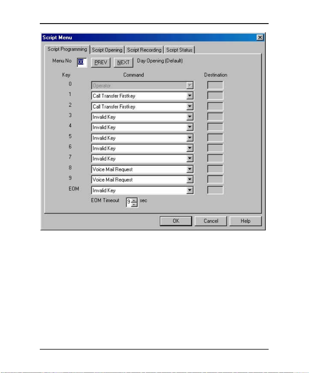
Programming by Computer
Figure 4-11 Auto Attendant Script Menu Dialog Box
The Key column contains the digit the caller can dial while the Automated
Attendant plays a script message. EOM (End of Message) refers to a
condition in which the script reaches its end and the caller has not dialed a
number.
The Command column describes the action the AVM JR. takes when the
caller dials a digit or the script message comes to an end. Each action
corresponds to a number in the DTMF column.
The Destination column lists to which extension, mailbox or submenu to
transfer the call.
Atlas AVM JR. Installation and Programming Manual 4-19
Page 74

Programming by Computer
1. In the Menu No. box, type the number of the script message you want to
program and press ENTER. Or press the NEXT and PREVIOUS buttons
to scroll through all of the script menus
The VUP displays past programming for the script message selected.
2. Under Command, click the arrow button to select an action for a
corresponding DTMF digit.
3. Under Destination, type an extension number, mailbox number or
submenu number, if applicable.
4. Click OK to save and return to the main menu.
4.7.2 Setting Up Different Script Menus Per Port
The AVM JR allows you to set up different Script Menus per port. To set this up
open the Script menu screen by selecting Auto Attendant and then Script Menu.
Then click on the Script Opening tab. The following screen will appear.
4-20 Atlas AVM JR. Installation and Programming Manual
Page 75

Programming by Computer
Figure 4-12 Script Opening Screen
The AVMJR allows for up to four different greetings per port when the system is
set to auto mode. To program the system to answer with a different script message
on a particular port select the port you wish to change, then select the mode that
you wish to change the script message for. Once you have selected the appropriate
item to change use the up and down arrow keys to select the new script number to
play. (This script will now replace the default script on that particular port for that
particular mode.)
The Number of Rings Before Answer field should be left at one. If you wish to
program a delay answer for the voicemail please refer to section E.1.4 or E.2.4
depending on your system.
Atlas AVM JR. Installation and Programming Manual 4-21
Page 76

Programming by Computer
4.84.8 Setting the Time, Date and Operation ModeSetting the Time, Date and Operation Mode
The VUP enables you to adjust the AVM JR. clock and calendar using a 24-hour
format.
ä To set the AVM JR. clock and calendar and mode:
1. On the Auto-Attendant menu, click Time & Date.
The Time & Date dialog box opens.
Figure 4-13 Date & Time Dialog Box
2. In the Time box, type a new time.
3. In the Date box, type a new calendar date.
4. In the Mode box, select the mode you wish the system to run in.
4-22 Atlas AVM JR. Installation and Programming Manual
Page 77

Programming by Computer
a.) Auto – The AVM JR will automatically switch among day, night, break
and holiday modes depending on a predefined schedule.
b.) Day – The AVM JR will operate in Day mode playing the appropriate
script menu(s) setup in section 4.7.2.
c.) Night – The AVM JR will operate in Night mode playing the
appropriate script menu(s) setup in section 4.7.2.
d.) Break – The AVM JR will operate in Break mode playing the
appropriate script menu(s) setup in section 4.7.2.
e.) Holiday – The AVM JR will operate in Holiday mode playing the
appropriate script menu(s) setup in section 4.7.2.
5. Click OK.
4.8.1 Setting up Auto Mode
Auto mode allows the AVM JR to switch between operation modes automatically
on a pre-defined schedule. This mode can switch between day, night, break and/or
holiday mode. To enable this you must set up the schedule for auto mode.
4.8.1.1 Programming Daily Schedules
To program the daily schedules click on the Auto-Attendant menu, click Time &
Date.
The Time & Date dialog box opens. Click on Schedules to edit the schedule
field. The following screen will appear:
Atlas AVM JR. Installation and Programming Manual 4-23
Page 78
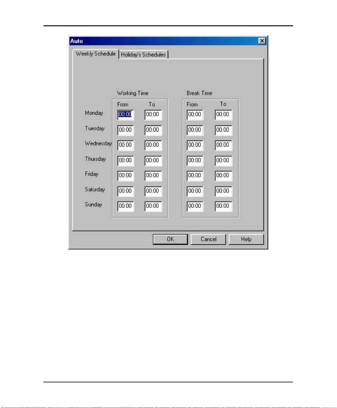
Programming by Computer
Figure 4-14 Auto Mode Schedule
At this point you should proceed to enter the working time and break modes for
each day of the week. The working time is the time of day the system will play the
day script menu. The system will play the night script menu at all other times
during the day except for the break time if it is entered.
4.8.1.2 Programming Holiday Schedules
The AVM JR allows you to set up an automatic holiday mode. This allows the
system to switch between normal operation and holiday mode on a pre-defined
schedule. To program the holiday schedule click on the Auto-Attendant menu,
click Time & Date.
4-24 Atlas AVM JR. Installation and Programming Manual
Page 79
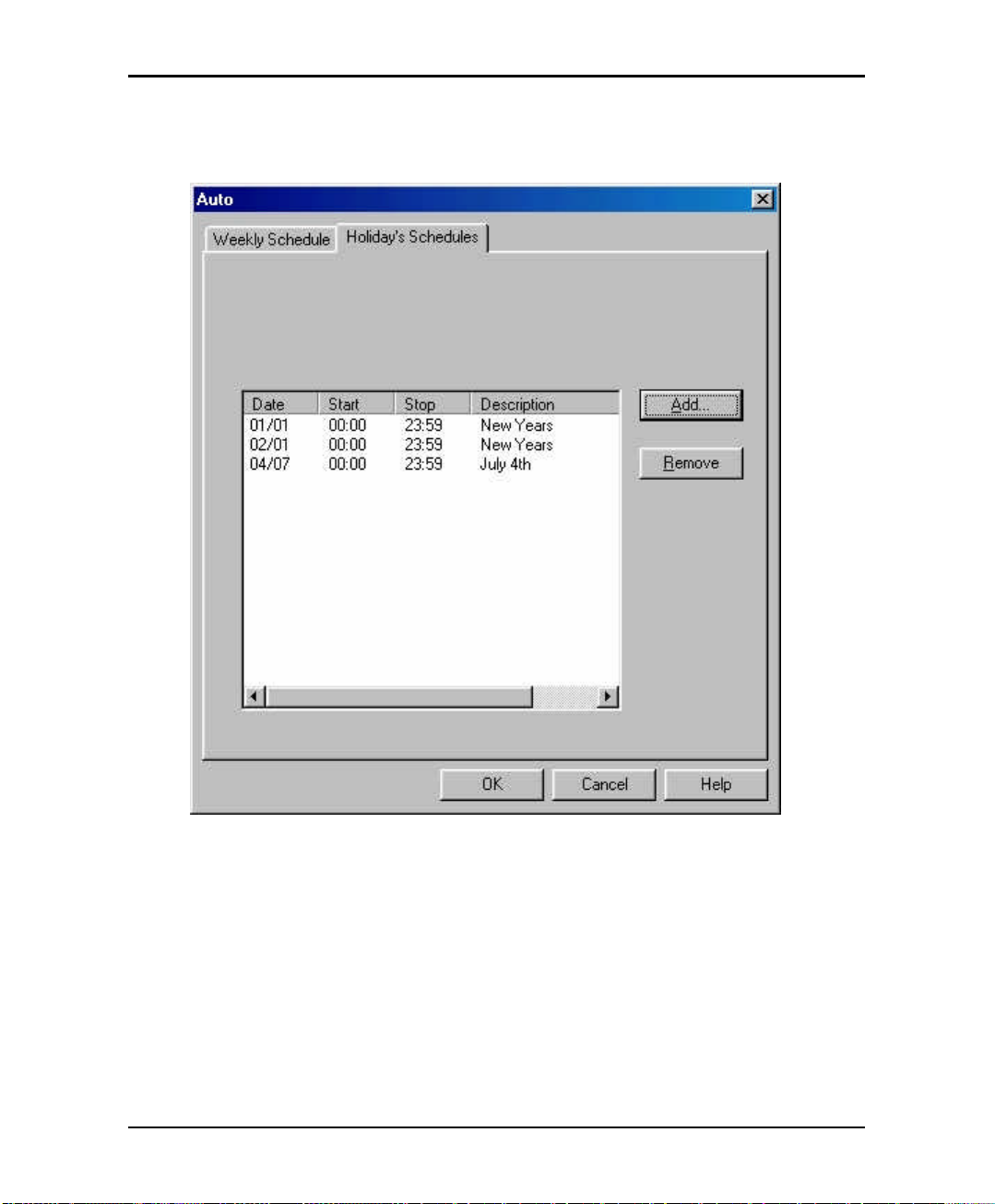
Programming by Computer
The Time & Date dialog box opens. Click on Schedules to edit the schedule
field, and then click on the Holiday Schedules tab. The following screen will
appear:
Figure 4-15 Holiday Schedule Screen
At this point you may either add or delete a scheduled holiday
4.8.1.2.1 Adding a Holiday
To add a holiday click on the add button. The add to holiday list screen will
appear. Select the day you wish to program the holiday greeting for by clicking on
the arrow next to the date and the selecting the day on the calendar by clicking on
the day you wish. Set the start and stop time and then give the holiday a
Atlas AVM JR. Installation and Programming Manual 4-25
Page 80

Programming by Computer
description for future reference. If you wish to have the holiday mode be in effect
all day long set the start time to 00:00 and the stop time to 23:59.
4.8.1.2.2 Removing a Holiday
To remove a holiday click on the date of the holiday you wish to remove and then
click on the remove key.
4.94.9 Working with Configuration FilesWorking with Configuration Files
You can program the AVM JR. parameters and save them as a file on your hard
disk. Later you can download the data on the file to the AVM JR..
ä To save the current parameters as a new configuration file:
1. On the File menu, click Save As.
2. In the Save As dialog box, type a file name.
3. Click OK.
ä To save current settings and values into an open configuration file:
•
On the File menu, click Save.
4.104.10 DDownloading Data to the ownloading Data to the AVM JR.AVM JR.
You can download data to the AVM JR. only if the VUP is online. See Section
4.1.
ä To download data to the AVM JR.:
1. On the Communication menu, click Send Parameters.
2. Type the System Administrator’s password and press ENTER.
If the password is correct, the data is downloaded from the PC to the AVM
JR.. If the password is incorrect, the VUP issues an error message and
asks you to retype the password.
4-26 Atlas AVM JR. Installation and Programming Manual
Page 81

Programming by Computer
4.114.11 Viewing Statistical Information Stored in the Viewing Statistical Information Stored in the AVM JR.AVM JR.
DatabaseDatabase
The VUP organizes statistical information stored in the AVM JR. database into the
following tables:
•
List of all new and saved messages, including mailbox number, date and time
of entry and status
•
List of messages per mailbox, including date and time of entry and status
•
Status of the flash memory, including total time available, amount of time
used, amount of time remaining and percent of memory used
•
Number of incoming calls on each line
ä To view statistical information stored in the AVM JR. database:
1. On the Communication menu, click Read Parameters.
2. On the Statistics menu, click the report you want.
3. Click OK to close the report and return to the main screen.
4.124.12 Printing ReportsPrinting Reports
You can organize and print reports on the AVM JR. parameters and on statistical
information stored in the AVM JR. database.
ä To print a report:
1. On the File menu, point to Print Settings Menu and click select the
information you wish to print out. You may only select one option from
this menu.
2. On the File menu, point to Print. The print screen will appear. Select the
correct printer and the number of copies.
3. Click OK.
Atlas AVM JR. Installation and Programming Manual 4-27
Page 82

Programming by Computer
4.134.13 Saving ReportsSaving Reports
You can organize and save reports on the AVM JR. parameters and on statistical
information stored in the AVM JR. database.
ä To save a report:
1. On the File menu, point to Print and click System Parameters to open
the System Parameters dialog box or Statistics to open the Statistics
dialog box.
2. Select the appropriate check boxes.
3. Click OK.
The Output Location dialog box opens.
4. Click To a File.
The Save As dialog box opens.
5. Type a file name and click OK.
The AVM JR. saves the report.
You can print the report from DOS or by using any Windows print utility.
4.144.14 Getting HelpGetting Help
You can get help on a topic in two ways:
•
Click Index on the Help menu to open the comprehensive online index.
•
Highlight a text box on any dialog box and press F1 to see a short description
of the option.
4.154.15 Closing the VUPClosing the VUP
ä To close the VUP:
•
On the File menu, click Exit.
4-28 Atlas AVM JR. Installation and Programming Manual
Page 83

5. USER OPERATING INSTRUCTIONS
5.15.1 IntroductionIntroduction
The following paragraphs describe the user’s operational menus.
5.25.2 User’s Main MenuUser’s Main Menu
When the caller user logs into their mailbox the AVM JR announces the number of
messages and then plays the user’s main menu.
DIGIT NAME DESCRIPTION
1 Retrieve Message Enter Retrieve Message menu
2 Mailbox Parameters Enter Mailbox Parameters menu
8 Send Message Send a message to a specific mailbox
9 Return to Auto
Attendant
Exit current menu and return to Auto
Attendant
5.35.3 RetRetrieve Message Menurieve Message Menu
If the mailbox owner dials “1” while in the user’s main menu, the AVM JR plays
the new messages, followed by previously saved messages. At the end of each
message, the AVM JR plays the Retrieve Message menu:
Atlas AVM JR. Installation and Programming Manual 5-1
Page 84

User Operating Instructions
DIGIT NAME DESCRIPTION
1 Next Message Plays the next message
2 Replay Replay the current message
3 Save Save the current message
4 Forward Forward current message to another mailbox
5 Reply Reply to message sender (Internal messages
only)
8 Delete Delete current message
9 Return to Previous Menu Return to previous menu (User’s main menu)
5.45.4 Mailbox ParametersMailbox Parameters
If the mailbox owner dials “2” while in the user’s main menu, the AVM JR plays
the Mailbox Parameters menu:
DIGIT
1 Record Greeting Record a greeting message for the mailbox
2 Record Name Record your name
3 Directory Listing Set directory listing parameters
4 Change Password Change the mailbox access password
6 External Notification Set the external notification parameters (if
7 Pager Notification Set the pager notification parameters (if
9 Return to Previous Menu Return to previous menu (User’s main
5-2 Atlas AVM JR. Installation and Programming Manual
NAME DESCRIPTION
allowed)
allowed)
menu)
Page 85

User Operating Instructions
5.4.1 Record Greeting
The mailbox owner can record a personal greeting by dialing “1” on the User’s
Parameters menu. The AVM JR then plays the Record Greeting menu:
DIGIT NAME DESCRIPTION
1 Play Back Play existing recording
2 Record Record a new greeting message
8 Delete Delete existing message
9 Return to Previous Menu Return to previous menu (User’s
parameters menu)
5.4.2 Record Name
The mailbox owner can record his personal name by dialing “2” on the user’s
parameters menu. The AVM JR then plays the Record Name menu:
DIGIT NAME DESCRIPTION
1 Play Back Play existing recording
2 Record Record a new name
8 Delete Delete existing name
9 Return to Previous Menu Return to previous menu (User’s
parameters menu)
5.4.3 Directory Listing
The mailbox owner can set the directory listing parameters by dialing “3” on the
user’s parameters menu. The AVM JR then plays the Directory Listing menu:
Atlas AVM JR. Installation and Programming Manual 5-3
Page 86

User Operating Instructions
DIGIT
NAME DESCRIPTION
1 Play Back Play current directory listing code
2 Change Change directory listing code
8 Delete Delete directory listing code
9 Return to Previous Menu Return to previous menu (User’s
parameters menu)
5.4.4 Change Password
A mailbox password consists of four digits. The default password is 1234. To
disable the password, enter 0000.
The mailbox owner can change their password by dialing “4” on the user’s
parameters menu. The AVM JR then plays the Change Password menu:
DIGIT NAME DESCRIPTION
1 Play Back Plays the current password
2 Change Change existing password
9 Return to Previous Menu Return to previous menu (User’s
parameters menu)
5.4.5 External Notification
If the System Administrator grants permission, the mailbox owner can:
•
Enable/disable remote notification
•
Enter their remote telephone number
•
Listen to the current remote telephone number
By dialing “6” on the user’s parameters menu.
5-4 Atlas AVM JR. Installation and Programming Manual
Page 87

User Operating Instructions
DIGIT NAME DESCRIPTION
1 Change Mode Toggles the external notification state
(enabled/disabled)
2 Telephone Number Enter the selected telephone number for
external notification. Codes1 0-9, extension
number, *, #, A-D, P and Q can be used
8 Play Back Play back the external telephone number
9 Return to Previous Menu Return to the previous menu (User’s
parameters menu)
Codes1:
P (1 second pause) = *1 # = *4 B = *6 D = *8 * = **
Q (4 second pause) = *2 A = *5 C = *7 Ext No. = *0 0-9 = 0-9
5.4.6 Pager Notification
If the System Administrator grants permission, the mailbox owner can:
•
Enable/Disable pager notification
•
Enter their pager number
•
Listen to the current pager number
By dialing “7” on the user’s parameters menu.
Atlas AVM JR. Installation and Programming Manual 5-5
Page 88

User Operating Instructions
DIGIT NAME DESCRIPTION
1 Change Mode Toggles the pager notification state
(enabled/disabled)
2 Pager Number Enter the selected pager number for pager
notification. Codes1 0-9, extension
number, *, #, A-D, P, Q and SID can be
used
8 Play Back Play back the pager number
9 Return to Previous Menu Return to previous menu (User’s
parameters menu)
Codes1:
P (1 second pause) = *1 # = *4 B = *6 D = *8 * = **
Q (4 second pause) = *2 A = *5 C = *7 Ext No. = *0 0-9 = 0-9
SID = *3 (SID will wait for the pager confirmation tone before the system
continues dialing <beep, beep, beep>)
5.4.7 Return to Previous Menu
The mailbox owner can dial “9” on the user’s parameters menu to return to the
user’s main menu.
5.55.5 Send MessageSend Message
The mailbox owner can leave a message in any mailbox or group of mailboxes by
dialing “8” on the user’s main menu.
5.65.6 Return to Auto AttendantReturn to Auto Attendant
The mailbox owner can dial “9” on the user’s main menu to return to the auto
attendant.
5-6 Atlas AVM JR. Installation and Programming Manual
Page 89

User Operating Instructions
5.75.7 Quick Reference GuideQuick Reference Guide
Atlas AVM JR. Installation and Programming Manual 5-7
Page 90

User Operating Instructions
This Page Intentionally Left Blank.
5-8 Atlas AVM JR. Installation and Programming Manual
Page 91

rt of voicemail.
6. TROUBLESHOOTING
This section presents answers to commonly asked questions on operating the AVM
JR..
If a problem persists, contact your Key System US dealer.
Q: Local notification does not work.
A:
•
Make sure you entered the correct notification codes.
•
Make sure that local notification is enabled.
•
Make sure that line 2 is properly connected to the AVM JR. and is
fully operational. Try calling into port 2 of the AVM JR.
•
Remove all the messages from the mailbox and then send a new
message.
Note: The AVM JR. only signals the KSU when it places a message in
an empty mailbox. The KSU then turns on the notification LED
on the telephone extension.
If an error occurred and the KSU did not receive the Message
Light On code, correcting the error does not turn the
notification LED on. Only first emptying the mailbox and then
sending a new message can turn the notification LED on.
•
Add a pause between codes.
•
Check message light codes. They should be 743x for on and 740x for
off.
•
Check dial 7 features in the phone system for the 2nd po
They need to be set to on.
Atlas AVM JR. Installation and Programming Manual 6-1
Page 92

Troubleshooting
Q: External Notification does not work.
A:
•
Make sure you selected the correct external access code.
•
Make sure you did not add the external access code to the telephone
number because the AVM JR. automatically dials the external access
code.
•
Make sure external notification is allowed and enabled.
•
Try dialing the external notification sequence on the 2nd port of
voicemail with your test set to make sure that the system is allowing the
call to be made.
•
Monitor the 2nd port during a notification attempt to try and determine
where the notification is failing.
Q: The AVM JR. does not transfer calls. DTMF tones are heard or the
call is disconnected.
A:
•
Flash 1 has been incorrectly configured.
•
The port cannot put a call on hold in system programming.
Q: When I dial command code *300, the AVM JR. plays an error
message.
A:
You are trying to change the number of digits in an extension after
extensions and mailboxes have been configured. To change the number of
digits in an extension, you must first remove all mailboxes and extensions.
6-2 Atlas AVM JR. Installation and Programming Manual
Page 93

Troubleshooting
Q: In supervised mode, the AVM JR. incorrectly recalls calls.
A:
The AVM JR.’s Time to Wait for No-Answer parameter value is greater
than the KSU’s hold recall time parameter value. Decrease the value of
the AVM JR.’s Time to Wait for No-Answer parameter or increase the
value of the KSU’s hold recall time parameter.
Q: In supervised mode, the AVM JR. does not recognize answered calls.
A:
•
Increase the Voice Sensitivity parameter value.
•
Make sure that the correct Transfer Supervision Type has been
selected.
Q: Command *510 does not allow a mailbox to be deleted.
A:
The mailbox is used in script menus. Please remove the mailbox from all
script menus and then use the delete command.
Q: The AVM JR. plays the wrong time stamp and does not play the user
messages.
A:
Make sure that you have recorded a Day Opening greeting. Until this
script is recorded, the AVM JR. is in test mode.
Q: The Voicemail Utility Program (VUP) issues a warning that the com
port is unavailable.
A:
•
Make sure that the selected COM port is not being used by another
device.
•
If the selected COM port was previously used by another device, shut
down and restart your computer to release the serial port.
Atlas AVM JR. Installation and Programming Manual 6-3
Page 94

Troubleshooting
Q: A message is sent to a mailbox group that contains five defined
mailboxes but only two mailboxes receive the message.
A:
The messages were sent to all the mailboxes in the group but only
accepted by those mailboxes that did not have the maximum number of
messages recorded.
Q: The AVM JR. has been programmed to operate in Night mode.
When a call is received, it disconnects the call and switches to Day
mode.
A:
Make sure that the night greeting script is recorded.
Q: What happens when a mailbox and mailbox group have the same
extension number?
A:
Messages are sent to the mailbox. In general, mailboxes have higher
priority than mailbox groups.
Q: I dialed “6” on the User menu and got an error message.
A:
Make sure that the external notification feature for the mailbox is allowed.
Q: DTMF’s dialed by AVM JR are not recognized by the KSU.
A:
Change the amplitude and the on and off levels of DTMF’s dialed by the
AVM JR. (*379, *371)
Q: How can I find out how much memory is supported by my AVM JR?
A:
Use statistics option in VUP.
Q: When I reach a mailbox a menu is played immediately and I am not
given a chance to leave a message.
A:
6-4 Atlas AVM JR. Installation and Programming Manual
The mailbox is defined as an announcer mailbox
Page 95

Troubleshooting
Q: I have disabled the Automatic Gain Control but the messages are
played louder then needed.
A:
Only messages recorded after the changes are effected. Initiate a new call
after the changing the AGC’s status.
Q: I have three digit extension numbers on my system and the AVM JR
defaults to two digit. How do I change the system to three digits?
A:
To change the system from two digit to three digit you must do the
following
1) Delete all mailboxes defined in the system using
mode *510. You need to delete mailboxes 10-29.
(Dial *510 10#, *510 11#, *510 12# etc.)
2) Reset legal extension group 0 to none using mode
*320. (Dial *320+0+00+00+#)
3) Change extension size to 3 in mode *300. (Dial
*300 + 3)
4) Set the range of valid extension numbers in mode
*320. (Dial *320 + 0 + SSS + EEE where SSS =
starting station number and EEE = ending station
number.)
5) Create new mailboxes using mode *500. (Dial *500
+ SSS + EEE + # where SSS = starting mailbox
number and EEE = ending mailbox number.)
Q: How can I remove the busy and no-answer menus when a caller is
returned to voicemail
Atlas AVM JR. Installation and Programming Manual 6-5
Page 96

Troubleshooting
A:
To remove the busy and no answer menus so that a caller goes directly to
the mailbox greeting you need to do the following two steps.
1) Program the EOM for script messages 21 and 23 to
voicemail request using mode *150. (Dial *150 + 21
+ * + # and *150 + 23 + * + #.)
2) Record a couple of seconds of silence in script
menus 21 and 23 using mode *100. (Dial *100 + 21
and *100 + 23. The system will give a beep, wait a
couple of seconds and then press the pound key. If
the system gives you an error tone repeat the above
step and wait a little bit longer before pressing the
pound key.
Note: If you are using a speakerphone to record the silence
pressing the MIC key will mute out any background noise.
6-6 Atlas AVM JR. Installation and Programming Manual
Page 97

7. APPENDIX A
The following table presents a summary of DTMF programming commands.
Note: The DTMF and PC columns list the sections in which the DTMF and
computer programming operations are discussed in this manual.
OPERATOR COMMANDS
OPERATION COMMAND DTMF PC
Day Light Savings Time
Change the operational mode
(without entering the
programming mode)
SCRIPT PROGRAMMING COMMANDS
OPERATION COMMAND DTMF PC
Directory listing format
Record a message
*7 + XXXX + Y
XXXX = operator’s password
Y = 0; Reduce the time by one
hour.
Y = 1; Increase the time by one
hour.
*8 + XXXX + Y
XXXX = operator’s password
Y = 0; Day
Y = 1; Night
Y = 2; Holiday
Y = 3; Auto
Y = 4; Break
*011 + X
X = 0; Directory by last name
X = 1; Directory by first name
*100 + XX + Beep + Record + #
3.8.3
3.8.4 4.9
3.7.3.1 4.5.2
3.7.1 N/A
Play a message
Delete a message
Atlas AVM JR. Installation and Programming Manual 7-1
*101 + XX + Beep + Playback
*102 + XX
3.7.1 N/A
3.7.1 N/A
Page 98

Appendix A
SCRIPT PROGRAMMING COMMANDS (CONT’D)
Select EOM timeout for each
script
Transfer to a script message
Select Opening Script
Transfer to opening menu
Transfer to an extension
Transfer to an operator
Transfer to a mailbox
Disconnect
Leave a message in a mailbox
*105 + XX + Y + #
XX = Script No.
Y = Timeout in seconds
*110 + XX + B +
Destination script message + #
*112 + XX + YY + Z + #
XX = Default script number 00,
10, 15 or 20
YY = Replacement script number
00-20
Z = Port number 1-4
*115 + XX + B + #
*120 + XX + B+ Extension +#
*125 + XX + #
*130 + XX + B + Mailbox + #
*140 + XX + B +Z +#
Z = 0, no message
Z = 1 with message
*150 + XX + B + #
XX = script No.
3.7.2.1 4.7
3.7.2.2 4.7
3.7.2.3 4.7.2
3.7.2.4 4.7
3.7.2.5 4.7
3.7.2.6 4.7
3.7.2.7 4.7
3.7.2.8 4.7
3.7.2.9 4.7
Retrieve messages from a
mailbox
Direct transfer to an extension
Direct transfer to a mailbox
Hold
Blind Transfer to Busy
Extension
Reset a specific message entry
to its default value
Reset all message entries to
defaults
7-2 Atlas AVM JR. Installation and Programming Manual
*160 + XX + B + #
XX = script No.
*170 + XX + first digit(s) + #
*175 + XX + first digit(s) + #
*180 + XX + B + #
*185 + XX + B + #
*190 + XX + B + #
*190 + XX + #
3.7.2.10 4.7
3.7.2.11 4.7
3.7.2.12 4.7
3.7.2.13 4.7
3.7.2.14 4.7
3.7.4 4.7
3.7.4 4.7
Page 99

Appendix A
PBX PARAMETERS
No. Of digits in extension
Cut off time for continuous
call progress tone detection
No. Of rings before the line is
answered
Time to wait for No Answer
PBX legal extensions
Operator ID code.
Key to retrieve messages
during mailbox greeting
playback
Disconnect code
External access code
Pause before and after
external access code
Transfer mode for all
extensions except the
operator’s extension
Day operator extension no.
*300 + X
*301 + X
X = cut off time in seconds (0-9)
*310 + line number + number of
rings
*311 + XX
*320 + Y +First Ext. + Last Ext.
+ #
Y = group number (0-9)
*330 + X
X = 0-9
*331 + X
X = 0-9; Retrieve digit
*333 + XXXX + #
*340 + X
X = external access digit (0-9)
*341 + X
X = pause length in seconds (0-9)
*350 + X + Y
X = 1; All extensions except the
operator
X = 2; Semi-Supervised
Y = 0; Non Supervised
Y = 1; Supervised
Y = 2; Semi Supervised
*360 + X + YYYY + #
X = 1; Day operator
X = 2; Night operator
X = 3; Fax extension
X = 4; Supervisor extension
YYYY = extension number
*360 + X + # to delete extension
3.3 4.5.1.1
3.3 4.5.1.4
3.3 4.5.1
3.3 4.5.1
3.3 4.5.1
3.3 4.5.1
5.2 N/A
3.3 4.5.2
3.3 4.6.6
3.3 N/A
3.7.5 4.5.2
3.3 4.5.1
Atlas AVM JR. Installation and Programming Manual 7-3
Page 100

Appendix A
PBX PARAMETERS (CONT’D)
Volume level
Flash 1
Voice sensitivity
Automatic Gain Control
(AGC)
DTMF amplitude
Procedural codes sent to the
PBX in order to perform a
specific task.
*369 + X
X = volume level (0-9) 9 =
loudest
*370 + XXX
*376 + X
*377 + X
X = 0 AGC disabled
X = 1 AGC enabled (Default)
*379 + X
X = volume level (0-9), 9 =
Loudest
*380 + X + CODE1 + #
X = 1; LED1 notification code
X = 2; LED2 notification code
X = 3; LED off code
X = 4; Transfer code
X = 5; Recall from busy
X = 6; Recall from no answer
Code = Respective PBX CODE
*380 + X + # to cancel code
3.3 N/A
3.3 4.5.1.2
3.3 4.5.2
3.3 4.5.2
3.3 4.5.1.3
3.3 4.5
1
SETTING TIME & DATE
Change the operational mode
*400 + X
3.5 4.9
X = 0; Day X = 3; Auto
X = 1; Night X = 4; Break
X = 2; Holiday
Select time stamp format
Set time and day
Set date
Listen to the system time
Set working hours
*410 + X
*420 + Hour + Minutes
*430 + Date + Month + Year
*440
*450 + Day + Starting time +
3.5 N/A
3.4 4.8
3.4 4.8
3.4 N/A
3.5 4.9
Ending time
7-4 Atlas AVM JR. Installation and Programming Manual
 Loading...