

Page 1

Installer’s Manual
Key System US
West Palm Beach, Florida
Page 2

ii Atlas AVM Installer’s Manual
Legal Notice
Key System US provides this document "as is," with no representations or warranties, either explicit or
implied, including but not limited to the implied warranties of merchantability, title, or fitness for a
particular purpose.
Key System US reserves the right to make changes in product software, hardware, or documentation at
any time, with no obligation to inform any persons or entities of such changes. Every attempt has been
made to ensure the accuracy of this document. However, Key System US assumes no responsibility for
any losses, whether electronic, financial, or other, that might accrue from inadvertent inaccuracies that
the software or documentation might contain.
Some states or jurisdictions do not allow disclaimer of explicit or implicit warranties in certain
situations. Therefore, this statement might not apply to you.
Copyright © 1997. Key System US. All rights under copyright reserved.
This software is furnished under a license or nondisclosure agreement. The right to copy this software is
limited by the license or agreement. One copy of the software may be made for archival purposes.
Making any other copies of the software, without prior written permission from Key System US, is
prohibited by copyright laws, and constitutes a punishable violation of those laws.
The contents of this document may not be duplicated by any means, whether electronic, graphic, or
mechanical, including, but not limited to, photocopying, recording, taping, or information recording
and retrieval systems, for any purpose but the original purchaser's personal use, without prior written
permission of Key System US.
Trademark Information
Atlas, Atlas AVM and Atlas IIE are registered trademarks of KS Telecom.
CO/Session is a registered of Triton Technologies, Inc.
Dialogic is a registered trademark of Dialogic Corporation.
MS-DOS is a registered trademark of Microsoft Corporation.
QEMM is a registered trademark of Quarterdeck Office Systems.
Rhetorex is a trademark of Rhetorex, Inc.
GammaFax is a trademark of GammaLink.
Key System US
4910 Dyer Blvd., West Palm Beach, Florida 33407
Page 3

Table of Contents
Chapter 1: Overview of Installation and Integration
About this Manual.......................................................................... 1-1
Evaluating the Customer ................................................................ 1-2
Gathering Integration Information.................................................. 1-3
Designing the Basic System ........................................................... 1-4
Planning the Design........................................................................ 1-4
Building the System ....................................................................... 1-4
Installing Voice Boards..................................................................1-5
Installing Atlas AVM ..................................................................... 1-5
Connecting Atlas AVM to a Telephone System .............................. 1-6
Integrating with the Telephone System........................................... 1-6
Installing and Configuring Fax (Optional)......................................1-6
System Administration Considerations...........................................1-6
Finalizing the Installation............................................................... 1-7
Table of Contents iii
Conventions............................................................................. 1-2
Sizing the System.................................................................... 1-4
Chapter 2: Quick Installation Guide
What is Atlas AVM? ............................................................... 2-1
Installation Procedure.............................................................. 2-1
Installation Steps............................................................................ 2-2
Chapter 3: Evaluating the Customer
Gathering Information.................................................................... 3-1
The Customer Engineering Form.................................................... 3-1
Company Information.............................................................. 3-2
Site Information....................................................................... 3-2
Telephone System Information................................................ 3-2
Telephony Applications/Features Desired ................................ 3-2
Chapter 4: Integration Investigation
Integration Requirements ............................................................... 4-1
Investigation Steps ......................................................................... 4-2
Understanding Data Packets .................................................... 4-3
The Integration Form...................................................................... 4-6
Telephone Scenarios.............................................................. 4-10
Data Packet Timeout and Termination................................... 4-15
Using a Digit Grabber............................................................ 4-16
Digit Grabber Set-up Procedure............................................. 4-17
Test Procedure....................................................................... 4-17
Data Packet Collection .......................................................... 4-17
Page 4

iv Atlas AVM Installer’s Manual
Chapter 5: Designing the Atlas AVM System
Planning the Basic Design.............................................................. 5-1
Sizing the System........................................................................... 5-2
Chapter 6: Installing Voice Boards
Understanding Voice Boards..........................................................6-1
Voice Board Installation ................................................................. 6-1
Dialogic Voice Boards ................................................................... 6-3
Rhetorex Voice Boards................................................................... 6-6
Call Progress Tones ........................................................................ 6-7
Setting Rhetorex Voice Boards..................................................... 6-11
Erlang Measurement................................................................ 5-3
Auto Attendant........................................................................ 5-5
Voicemail................................................................................ 5-6
Ports Required......................................................................... 5-6
Voice Storage.......................................................................... 5-7
Unpacking and Handling the Boards........................................ 6-1
Installing the Voice Boards...................................................... 6-1
Attaching the Cables................................................................ 6-2
Basic Analog Configuration..................................................... 6-4
Multiple Board Configurations ................................................ 6-4
Dialogic Telephone Connectors............................................... 6-5
Rhetorex Telephone Connectors.............................................. 6-6
Tone Characteristics................................................................ 6-8
Supervised Transfers ............................................................... 6-8
AccuCall Plus (Rhetorex only) ................................................ 6-9
Chapter 7: Building the System
Environmental Considerations ........................................................ 7-1
Power Supply Considerations .................................................. 7-1
Hardware Specifications ................................................................. 7-1
Hard Drive Size.............................................................................. 7-3
Chapter 8: Connecting Atlas AVM to a Telephone
System
Telephone System Integration Definitions...................................... 8-1
Full Integration ........................................................................ 8-1
Partial Integration.................................................................... 8-1
Restricted Integration .............................................................. 8-2
Integration Types ........................................................................... 8-2
Serial Integration..................................................................... 8-2
Serial Integration with Additional Equipment .......................... 8-3
Possible Integration Features.......................................................... 8-4
Chapter 9: Integrating with the Telephone System
System Default Configuration ........................................................ 9-1
Page 5

Understanding the Integration Screens............................................ 9-1
Parameters............................................................................... 9-2
Voice Board Considerations .................................................... 9-2
Accessing the Integration Screens .................................................. 9-2
Global Parameters..........................................................................9-2
The Edit Global Parameters Screen 1....................................... 9-5
Telephone System Panel .......................................................... 9-5
Dialogic Control Block Panel..................................................9-5
The Serial Port /Integration Control Panels .............................. 9-2
Port Parameters ............................................................................ 9-17
Edit Port Telephone Parameters Screen 1 .............................. 9-17
The Sequences Panel............................................................. 9-31
The Edit Port Telephone Parameters Screen 3 ....................... 9-33
Edit Port Telephone Parameters Screen 4 .............................. 9-34
The Edit Port Telephone Parameters Screen 5 ....................... 9-36
Edit Port Telephone Parameters Screen 6 .............................. 9-37
Edit Port Telephone Parameters Screen 7 .............................. 9-38
Chapter 10: Fax Installation
Configuring the Fax Board........................................................... 10-1
Setting the I/O Port Addresses............................................... 10-1
Setting the AEB Signaling..................................................... 10-2
Cabling the Fax and Voice Boards................................................ 10-2
Installing the GammaFax Drivers................................................. 10-2
For Systems with More Fax Channels than Voice Board Ports10-3
Configuring the AUTOEXEC.BAT File....................................... 10-4
Table of Contents v
Chapter 11: System Administration Considerations
System Administration Steps........................................................ 11-1
Chapter 12: Final Cutover
Glossary
Index
Page 6

vi Atlas AVM Installer’s Manual
This Page Intentionally Left Blank.
Page 7

Table of Figures
Figure 2-1: Minimum Hardware Specifications................................................... 2-2
Figure 4-1: Using a Digit Grabber..................................................................... 4-16
Figure 5-1: Erlang Table..................................................................................... 5-4
Figure 6-1: Cord Connections for Dialogic Boards.............................................. 6-5
Figure 6-2: Rhetorex Telephone Connectors.......................................................6-6
Figure 7-1: Minimum Hardware Specifications................................................... 7-2
Figure 7-2: Suggested Hardware Configuration................................................... 7-2
Figure 7-3: Recommended Hard Drive Size........................................................ 7-3
Figure 8-1: Example of Serial Integration...........................................................8-2
Figure 8-2: Serial Integration with a Voice Bridge.............................................. 8-3
Figure 8-3: Example of In-Band Integration........................................................ 8-4
Figure 9-1: The Passcode Entry Box on the Main Status Screen.......................... 9-3
Figure 9-2: The System Administration Menu..................................................... 9-3
Figure 9-3: Global Options ................................................................................. 9-4
Figure 9-4: The Telephone System and, Dialogic Control Block......................... 9-5
Figure 9-5: The Telephone System and Rhetorex ................................................ 9-9
Figure 9-6: The Serial Port and Integration Control Panels ............................... 9-12
Figure 9-7: The Serial Packet Separation Screens ............................................. 9-14
Figure 9-8: Hex Conversion Chart .................................................................... 9-16
Figure 9-9: The Telephone System and............................................................. 9-18
Figure 9-10: The Telephone System and Rhetorex Channel Parameters Panels. 9-25
Figure 9-11: The Sequences and Message Waiting............................................ 9-31
Figure 9-12: Valid Characters for the Sequences Panel..................................... 9-32
Figure 9-13: The Control Panel ......................................................................... 9-33
Figure 9-14: The Tone Termination (Dialogic Only) and.................................. 9-34
Figure 9-15: The Integration and In-Band Supervision Panels ........................... 9-36
Figure 9-16: The In-Band Signaling Control Panel............................................ 9-37
Figure 9-17: The Integration Data Packet Screens............................................. 9-38
Page 8

viii Atlas AVM Installer’s Manual
This Page Intentionally Left Blank.
Page 9

Overview of Installation and
Integration
About this Manual
The purpose of this manual is to guide you through the installation and
integration of your Atlas AVM system. This manual is intended for use by
certified Atlas AVM installers who are proficient in DOS, telephony, and
voice processing.
The chapters in this manual are as follows:
• Chapter 1 gives a brief description of each chapter, provides a
summary of installation, and explains the conventions used in this
manual.
• Chapter 2 is a quick guide to installation for experienced
installers.
• Chapter 3 describes evaluating the customer’s voice processing
needs and capabilities.
• Chapter 4 offers an overview of the Atlas AVM installation and
integration process.
• Chapter 5 tells how to plan the basic design of an Atlas AVM
system.
• Chapter 6 describes the functions of voice boards in your Atlas
AVM system and tells which models of the Dialogic and Rhetorex
boards can be used.
• Chapter 7 gives general guidelines and recommendations for
building an Atlas AVM system.
• Chapter 8 gives suggestions for connecting Atlas AVM to your
telephone system.
• Chapter 9 tells how to program the Atlas AVM integration
screens.
• Chapter 10 explains how to add fax capability in your Atlas
AVM system.
1
Page 10
1-2 Atlas AVM Installer’s Manual
☞
• Chapter 11 covers the system administration issues that need to
be addressed as part of the installation process.
• Chapter 12 discusses the final steps required to make the system
operational.
• Glossary
• Index
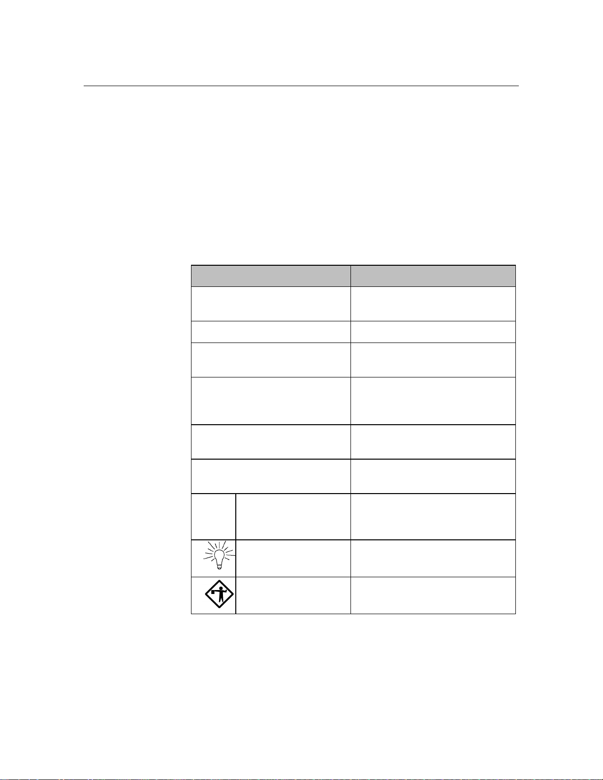
Conventions
This manual uses the following conventions:
CONVENTION KEY INFORMATION
lowercase x indicates a variable in a file,
ALL CAPS indicates a file or directory
<italics> indicates a variable or place
version, etc.
holder
Boxes➞Renumber
< > indicates a keyboard command
Lowercase bold used for commands or data to be
Note: Information that is vital to the
Tip: A shortcut or helpful hint
Caution: Possible damage to equipment
Evaluating the Customer
Before installing an Atlas AVM system, you need to gather information
about the prospective customer. This will help you assess what that
customer needs to build a voicemail system.
example of a ‘path’ that a user can
follow to get to a particular screen
or field.
entry such as <Enter>
typed at the keyboard
success of a process
1.
Collect pertinent information about the company.
Page 11

Overview of Installation and Integration 1-3
2. Decide which telephony features and applications the customer desires
such as:
• Voicemail
• Auto attendant
• Audiotext
• AMIS-Analog Networking
• Fax
3.
Determine whether the customer can or does meet the hardware and
software requirements. (See Chapter 9, “Building the System.”)
4.
Use the Customer Engineering Form in Chapter 3, “Evaluating the
Customer,” as you compile information about the customer.
Gathering Integration Information
In an Atlas AVM system, integration means enabling communication
between Atlas AVM and a specific telephone system.
Telephone systems differ, and Atlas AVM must be programmed to
communicate with the customer’s specific telephone system. To
accomplish this you need to gather information about the customer’s
telephone system.
1.
Collect the telephone system information suggested on the Integration
Form found in Chapter 4, “Integration Investigation.” This includes:
• Manufacturer, model, and software version
• Name of the person who maintains and services the
telephone system
• Necessary hardware for voice messaging
• Information about telephone system operations
• Data packet information
Resources for doing this include the Atlas Telephone System
Compatibility Listing, the customer’s interconnect, the telephone
system manufacturer, and the telephone system documentation.
2.
Gather any other needed information through on-site testing.
3.
If you have affirmed that Atlas AVM can integrate acceptably with the
customer’s telephone system, save the information you have compiled
for later use in the installation/integration process.
Page 12

1-4 Atlas AVM Installer’s Manual
Designing the Basic System
Planning the Design
You will need to draw up a basic design from the information you have
obtained from the customer. This will lay the groundwork for the system
and help you determine sizing issues (see “Sizing the System” below).
With the customer, you can help make decisions about how the overall
system will work. The following steps will help you do this.
1.
Design how the Auto Attendant will handle calls. This includes:
• Designing greetings which can be set for different times
(business hours vs. non-business hours), days and ports
• Designing the options available for transferring from the
Auto Attendant
☞
Note
Customizing and
programming boxes is
explained in the Atlas
AVM System
Administrator’s
2. Plan audiotext boxes in addition to the Auto Attendant. This includes:
• Determining the total number of audiotext boxes
• Planning audio menus
• Mapping the levels of audiotext boxes
3. Determine the number of voicemail, etc. boxes needed.
Sizing the System
After you have calculated the number of audiotext and voicemail boxes
required for an Atlas AVM system, you also need to determine the number
of voice board ports and the amount of disk storage required.
For worksheets and information regarding sizing, see Chapter 5,
“Designing the Atlas AVM System.”
Building the System
Keep in mind the following as you build your Atlas AVM system:
1.
Software requirements
• Atlas AVM installation disks
• DOS 5.0 or later, 6.2 recommended
• Fax Driver Disk (optional—available from Key System US)
• CO/Session 7.0 or later
Page 13

2. Hardware requirements
• Minimum hardware specifications (memory for CPU and ports)
• Suggested hardware configuration
• Recommended hard drive size
• Voice boards to handle number of ports required for the system
For information on system requirements, see Chapter 9, “Building the
System.”
Installing Voice Boards
You need to consider the following:
1.
Familiarize yourself with the voice boards Atlas AVM supports. You
can help the customer decide which voice boards to buy based on the
number of ports required, the number of available slots, and the cost
of different boards.
Overview of Installation and Integration 1-5
2.
Prior to installing voice boards, determine the following for your
system (Atlas AVM will suggest defaults during Atlas AVM
installation):
• I/O port address
• Hardware interrupt
• Base memory
3. Use the Rhetorex utility SHOWJUMP or the Dialogic voice board
documentation to determine the jumper settings for the I/O port
address before installing the voice boards. You can do this during or
after installation of the Atlas AVM software.
4.
Finally, physically connect the voice board(s) to the telephone system
using a telephone line. Determine the correct jack connection for the
voice board and make sure it matches the telephone jack connections
on the wall.
For information on setting up and installing voice boards, see Chapters 6,
7, and 8.
Installing Atlas AVM
The following steps are required for installing Atlas AVM:
2.
Make sure DOS is running.
Page 14

1-6 Atlas AVM Installer’s Manual
3. Install the voice board(s).
4.
Attach the hardware lock.
5.
Install the Atlas AVM disks.
6.
Install and configure CO/Session (optional).
7.
Create a VXNIGHT.BAT file (optional).
8.
Reboot the system.
For information on installing the Atlas AVM software, see Chapter 10.
Connecting Atlas AVM to a Telephone System
Determine the type of integration desired and what will be needed to complete
the connection.
For information on Connecting Atlas AVM to a Telephone System, see
Chapter 11.
Integrating with the Telephone System
This process involves taking the information you have collected and
inputting it into the Atlas AVM installation screens.
1.
Refer to the Integration Form you filled out earlier as you program the
Atlas AVM integration screens and parameters.
2.
Plan to test the integration after you have completed “System
Administration Procedures” below.
For instructions on programming the Atlas AVM integration screens, see
Chapter 12.
Installing and Configuring Fax (Optional)
Fax capability is an add-on feature that must be purchased separately.
Install and configure a GammaFax MLCP-4/AEB board, and install and
configure the fax drivers provided by Key System US.
For more information, see Chapter 13, “Fax Installation.”
System Administration Considerations
Page 15

Overview of Installation and Integration 1-7
Now that Atlas AVM is installed and integrated with the telephone
system, you need to instruct or assist the system administrator in the
following areas:
1.
Configuring system boxes—voicemail, audiotext, etc.
2.
Recording the audio portion of company greetings and other audiotext
boxes.
3.
Testing the system.
• System design
• Integration with the telephone system
(For detailed administration information, see the Atlas AVM System
Administrator’s Manual.)
4.
Training users on how to use the Atlas AVM telephone interface (can
be done by the installer or the system administrator).
The Atlas AVM Pocket Reference Guide provides information on
using the telephone interface. Atlas AVM also provides a tutorial
over the telephone when box owners first set up their voicemail boxes.
Finalizing the Installation
Now that you have Atlas AVM installed, configured, and tested, you can
take the final steps necessary to make the system operational. These steps,
called the final cut over, include:
1.
Connecting single line extensions to Atlas AVM.
2.
Programming Atlas AVM lines at the telephone switch.
3.
Organizing lines going to Atlas AVM into a hunt group.
4.
Forwarding trunk calls (outside calls) to Atlas AVM.
5.
Programming telephone handsets.
Some of these steps may require the expertise of the customer’s telephone
interconnect.
Page 16

1-8 Atlas AVM Installer’s Manual
This Page Intentionally Left Blank
Page 17

Quick Installation Guide
This chapter is an abbreviated version of Chapter 10, “Installing Atlas
AVM.” For more detailed installation information, see Chapter 10.
What is Atlas AVM?
Atlas AVM is a DOS-based voice processing system that provides a suite
of telephony features, as well as the means of integrating with a telephone
switch.
Installation Procedure
Briefly, installing and setting up Atlas AVM involves the following:
2
1.
Installing and setting up your voice boards.
2.
Installing and configuring CO/Session to allow remote maintenance.
3.
Installing the Atlas AVM disks and configuring your voice boards.
4.
(optional) Creating a VXNIGHT.BAT file, a custom batch file Atlas
AVM runs daily at 4:00 AM.
5.
Integrating with the specific telephone system, if necessary, through
the Atlas AVM installation screens.
6.
Using the Atlas AVM System Administrator’s Manual to set up Atlas
AVM system parameters.
Page 18
2-2 Atlas AVM Installer’s Manual
Installation Steps
Step 1: Equipment Inventory
Verify that you have all the needed equipment and software to complete a
total installation of the Atlas AVM voice processing system:
• A computer equipped with the hardware listed in Step 2 below
• DOS (version 5.0 minimum, 6.2 or later preferred)
• Atlas AVM installation package:
- Installation disks
- Hardware lock
- Atlas AVM System Administrator’s Manual
- Atlas AVM Installer’s Manual
- Atlas AVM User Guide pamphlets (25 copies)
• Dialogic or Rhetorex voice board(s)
• Miscellaneous telephone equipment for connecting to the
telephone system.
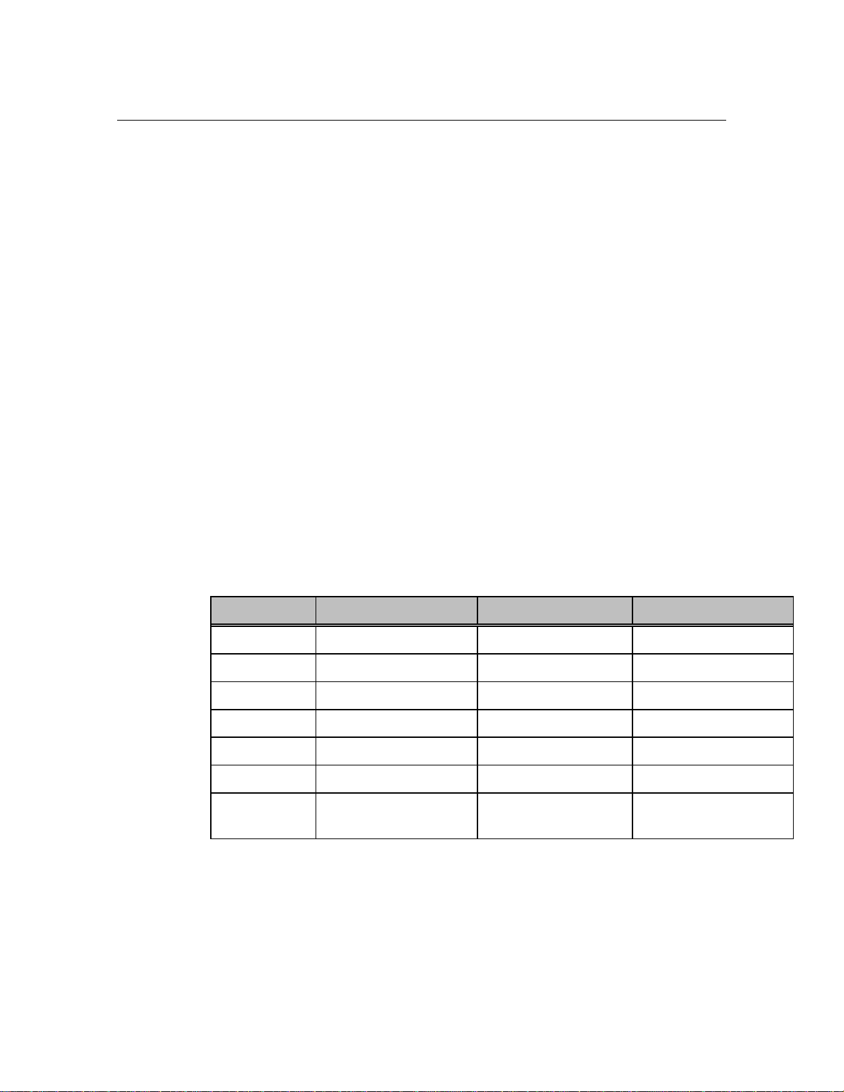
Step 2: Verify Hardware Requirements
Certain hardware specifications and configurations are required before a
PC can be utilized for Atlas AVM voice processing.
Component 4-12 Port System 16-20 Port System 24 Port System
CPU
RAM
Bus
Speed
Hard drive
BIOS
Power
supply
386, 486, or Pentium 486DX to Pentium 486DX4 to Pentium
4 MB 8 MB 12 MB
ISA ISA ISA
25-66 MHz or higher 33-66 MHz or higher 66 MHz or higher
IDE or SCSI IDE or SCSI IDE or SCSI
AMIBIOS AMIBIOS AMIBIOS
200 watt UL approved 250 watt UL approved 300 watt UL approved
Figure 2 -1: Minimum Hardware Specifications
Step 3: Voice Board Setup and Installation
Install your voice boards. Information on installing voice boards is
provided in Chapters 7 and 8.
Page 19

Quick Installation Guide 2-3
Step 4: Attach the Hardware Lock
Attach the hardware lock you received with your installation disks to
LPT1.
Step 5: Have DOS running
You need DOS version 5.0 or later.
Step 6: Load the Atlas AVM Disks
In this step you will load the Atlas AVM software, load the voice board
drivers, install QEMM, and configure your voice board.
The following disks are included in your Atlas AVM installation package:
Engine Disk 1
Engine Disk 2
Switch Integration Disk
Rhetorex Driver Disk
Dialogic Driver Disk 1
Dialogic Driver Disk 2
System Prompts Disk 1
System Prompts Disk 2
System Prompts Disk 3
QEMM Disk 1
QEMM Disk 2
Fax Driver Disk (if you have purchased the optional fax capability)
To begin installing, insert Engine Disk 1. Use a: install. Follow the prompts.
For a complete guide to all the installation screens, see Chapter 10,
“Installing Atlas AVM.”
Step 7: Create VXNIGHT.BAT (Optional)
Daily at 4:00 A.M. Atlas AVM offers the option of running a batch file of
your own making. For Atlas AVM to run this file, it must be named
VXNIGHT.BAT and must be located in the Atlas directory.
You can use your custom VXNIGHT.BAT file to perform automated tasks
related to your Atlas AVM system. For example, the following would
back up and then reboot/purge your Atlas AVM system:
xcopy c:\Atlas\*.* /e/s/v g:\
c:\coldboot.com
Page 20

2-4 Atlas AVM Installer’s Manual
Step 8: Install CO/Session
CO/Session allows remote maintenance of Atlas AVM, and also will
allow Key System US technical support personnel to access your Atlas
AVM system if you need assistance.
For more information, see Step 6, “Setting Up CO/Session,” in Chapter
10.
Step 9: Install Fax Capability (Optional)
You can purchase optional fax capability for your Atlas AVM system. For
more information, see Chapter 13, “Fax Installation.”
Step 10: Reboot the System to Verify all Settings
Reboot your system and look for error messages.
Your Atlas AVM system is now running on system defaults. If your
system is working with the default telephone system settings, refer to the
Atlas AVM System Administrator’s Manual for information on port setup
and programming system boxes (audiotext, voicemail, etc.).
If your system is not working with the defaults, see Chapter 12,
“Integration with the Telephone System,” for information on interfacing
with your specific telephone system.
Page 21

Evaluating the Customer
When you meet with customers who are interested in Atlas AVM,
determine what their companies need to build a voicemail system.
Evaluating customers’ situations and determining their needs will help
you guide them in developing an Atlas AVM system. The final decisions
should be based on considerations such as:
• Type of telephone system
• Telephony needs of the customer
• Cost of implementing everything required
Some customers may have telephone systems that do not have voicemail
capability, especially if they have older, smaller systems. If that is the
case, the customer will need to upgrade the telephone system in order to
have voicemail. Atlas AVM requires only basic voicemail capabilities
from the telephone system.
3
Gathering Information
Begin the evaluation process by collecting information about the
prospective customer and recording it on a form such as the Customer
Engineering Form given in this chapter. Use this as the basis for building
a file on the customer.
The Customer Engineering Form
Some of the information you need to gather relates to your role as a
salesperson; other parts relate to your role as an Atlas AVM installer.
Use the descriptions below as you fill out the Customer Engineering form.
Page 22

3-2 Atlas AVM Installer’s Manual
Company Information
Record the company name and address, the name of your contact person at
the company, and also the person who will make the final decisions about
purchasing an Atlas AVM system.
Site Information
Determine the approximate number of people who will be using voicemail
and make an estimate of how many boxes this system will need. This will
help you get a rough estimate of the size and cost of the Atlas AVM
system.
Find out how many telephone lines there are from the central office to the
company so you will know if additional lines will be required.
Telephone System Information
Collect information about the telephone system, including the
manufacturer, model number, and what software version is running. You
may need to get some of this information from the company’s interconnect
(telephone maintenance person).
Make a record of the name, address, and telephone number of the
company’s interconnect. The interconnect’s knowledge about the
telephone system can benefit you throughout the sales and installation
process.
Telephony Applications/Features Desired
Find out if the company wants its voicemail system to have an Auto
Attendant, voicemail, audiotext boxes, fax boxes or a combination of
these features.
Page 23
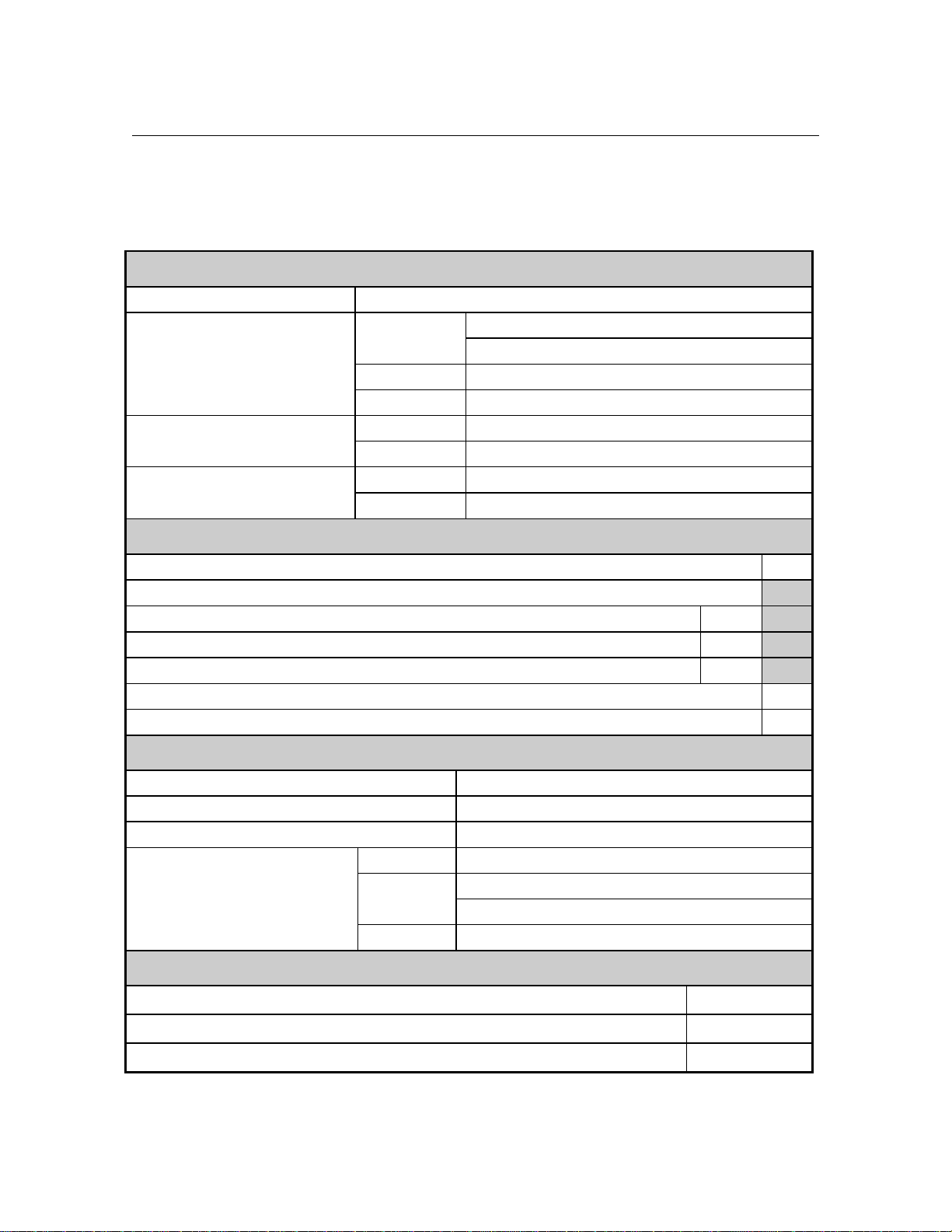
Customer Engineering Form
Company Information
1. Company name
2. Company information Address
Phone
Fax
3. Contact person Name
Phone
4. Final decision-maker Name
Phone
Site Information
5. Number of employees who will use the Atlas AVM system
6. Estimated number of boxes
Voicemail boxes (boxes for voicemail users)
Auto Attendant boxes (boxes for company greetings)
Audiotext boxes (boxes providing information)
7. Number of lines from central office
Evaluating the Customer 3-3
Estimated total number of boxes
Telephone system Information
8. Telephone system manufacturer
9. Telephone system model
10. Telephone system software version
11. Interconnect company Name
Address
Telephone
Telephony Applications/ Features Desired
12. Voicemail
13. Auto Attendant
14. Audiotext
Yes / No
Yes / No
Yes / No
Page 24

3-4 Atlas AVM Installer’s Manual
This Page Intentionally Left Blank.
Page 25

Integration Investigation
During the integration investigation, you will determine if Atlas AVM can
be integrated with the customer’s telephone system and what voicemail
features will be available.
Integration Requirements
Atlas AVM requires the following basic features from a telephone system
in order to have voicemail:
• Necessary software version for voicemail
The telephone system software may need to be upgraded if it is
not a voicemail capable version.
4
• Single-line extensions
The voice boards in Atlas AVM are analog boards and need
single-line analog extensions. The user’s telephone does not need
this type of extension, only the lines going into Atlas AVM.
• Ringing capability on the single-line extensions
The telephone system must have ringing capability because the
voice boards and voice board drivers used in Atlas AVM require
the use of ringing as their method of notification.
• End-to-end DTMF
The Atlas AVM system sends and receives address information
for calls in the form of DTMF (Dual Tone Multi-Frequency)
signals. The phrase ‘end to end’ refers to the ability of a device to
both send and receive DTMF signals.
The following section, “Investigation Steps,” gives some possible ideas
for bringing a system that lacks some of the necessary requirements up to
standard.
Page 26

4-2 Atlas AVM Installer’s Manual
Investigation Steps
The information required to determine if successful integration is possible
can be obtained from the telephone system’s documentation or
manufacturer, the customer’s interconnect vendor, or through on-site
testing. (Some methods of on-site testing are covered in the Atlas
Certified Network Telephony Engineer Course Manual.)
As you gather the integration information listed in the following steps,
enter the data in the corresponding sections of the Integration Form
beginning on Page 4-7.
1.
Document general information about the customer and the telephone
system.
2.
Find out if the telephone system software supports voicemail.
You will probably need to consult the company’s telephone
representative to find out what software version is installed on the
telephone system, and what features this software has.
3.
Find out if the telephone system has the necessary hardware for
voicemail.
Locate single line extensions
If the customer has a fax machine or modem lines that go through
the telephone system, those are single line extensions. Find out
how many single lines there are.
If there are currently no single line extensions, you can add a
single line card (SLC) to the telephone system. These are also
called industry standard telephone cards (IST), or off-premise
extension cards (OPX).
Check for ringing on single line extensions
Dial a single line extension from another single line extension to
see if you hear ringing over the telephone.
The voice boards and their drivers used in Atlas AVM necessitate
the use of ringing as the method of notification. Therefore, the
telephone system has to have ringing capability on the extensions
going to Atlas AVM.
If the telephone system does not currently have ringing capability,
you can add a ‘ring generator’ card.
Check for end-to-end DTMF
• Attendant console
• Single line handset
• Digital handset
Page 27

Integration Investigation 4-3
The voice boards in the Atlas AVM machine, being analog
devices, necessitate the use of DTMF as the method of receiving
control information.
If the telephone system cannot provide DTMF on the extensions
going to Atlas AVM, then an additional DTMF generator board
must be added to the telephone system.
4.
Find out how the telephone system operates concerning the following:
• hunt groups
• disconnects
• supervised transfers
• event signaling
• off-premise transfers
5.
Make a list of equipment or software that needs to be upgraded.
6.
Obtain information about the data packets that are sent by the
telephone system.
You can gather this information from the customer’s interconnect
or from the telephone system vendor. If you cannot collect this
information through these avenues, or you want to confirm the
information you have collected, you will need to use a digit
grabber. For an example of how to use a digit grabber, see Page
4-16.
You will enter the data packet information you have gathered
when you are ready to program the Atlas AVM integration screens
covered in Chapter 12, “Integrating With the Telephone System.”
You do not need to input every data packet into Atlas AVM—
only the ones that will be relevant for Atlas AVM operations.
These would include such packets as ‘forward, busy,’ ‘forward, no
answer,’ ‘retrieve message,’ and possibly a ‘disconnect.’
Read the information in the next section, “Understanding Data
Packets,” before you fill out the data packet portion of the
Integration Form.
Understanding Data Packets
The data packet investigation involves the following three parts:
• Events and Packet Identifiers
• Packet Formats
• Atlas AVM Packet Definitions
Page 28
4-4 Atlas AVM Installer’s Manual
Manual
Events and Data Packet Identifiers
☞
Note
Contact your telephone
system installer or
manufacturer for the
correct codes to use in
defining types of calls
in the integration data
packets. If this is not
possible, you may be
able to recreate the call
type and monitor it on
the Diagnostic Trace
screen. (See the Atlas
AVM System
Administrator’s
You must learn the ‘events’ the telephone system sends data packets on
and their corresponding ‘packet identifiers’ (i.e. the code used to denote
that event).
Example:
Forward, busy 2
Forward, no answer 3
Retrieve message 4
Disconnect 7
Event Packet Identifier
☞
Note
The telephone
system may not send
a data packet for
each of the Atlas
AVM data packet
definitions.
Data Packet Formats
You must learn the packet format of the data packets. This involves
knowing what part of the data stream pertains to such things as the packet
identifier, the called party extension, the calling party extension, and
possibly other information.
Example:
The telephone system could send a string of digits to Atlas AVM
that communicates the called party extension and the packet
identifier:
1332
Atlas AVM must know what the packet format is in order to
understand this communication. Since there is no standard default
packet format, Atlas AVM does not know whether the packet
identifier is ‘1’ and the called party extension is ‘332,’ or if the
called party extension is ‘133’ and the packet identifier is ‘2.’
However, if we tell Atlas AVM what positions in the data packet
relate to what information, then Atlas AVM can understand this
data packet.
Page 29

Integration Investigation 4-5
If the called party was ‘133,’ and the packet identifier was ‘2’ (for
example, a forward busy), then the packet format would be:
Data Packet: 1 3 3 2
Positions: 0 1 2 3 4 5 6 7 8 9
Packet Identifier: 2
Packet Identifier Offset (position) 3
Packet identifier Length: 1
Called Party Offset (position): 0
Called Party Length: 3
Atlas AVM Definition of a Data Packet
For every data packet that you input into Atlas AVM, you must tell Atlas
AVM how it should ‘define’ that packet. The following section contains
the current possible data packet definitions and how Atlas AVM acts for
each definition.
Atlas AVM Data Packet Definitions
Direct to Box
The call goes directly to a box owner’s mailbox, without ringing the
extension, based on the ‘called party’ information. Atlas AVM plays the
box owner’s personal greeting without any additional prompts.
Forwarded
Atlas AVM plays the following prompt:
“<Name of box owner> is not available to take your call.”
Atlas AVM then sends this call to the box number of the ‘called party’
and carries out whatever is in the Busy Option field (e.g., Take
Message, Alternate Extension, Caller Options).
Atlas AVM plays the following prompt:
“I’m sorry, that extension is busy.”
Atlas AVM then sends this call to the box number of the ‘called party’
and carries out whatever is in the Busy Option field (e.g., Take
Message, Alternate Extension, Caller Options).
Page 30

4-6 Atlas AVM Installer’s Manual
Forwarded No Answer
Atlas AVM plays the following prompt:
“I’m sorry, that extension does not answer.”
Atlas AVM then sends this call to the box number of the ‘called party’
and carries out whatever is in the No Answer Option field (e.g., Take
Message, Alternate Extension, Caller Options).
Retrieve Message
Atlas AVM recognizes the caller as a box owner, sends the call to a box
based on the ‘called party’ information, and then asks for the passcode
for that box.
Trunk
Atlas AVM recognizes the call as being a ‘trunk’ call. This means that
the Trunk Port field on the Integration Data Packet Parameters screen is
valid. Atlas AVM plays the port greeting or Auto Attendant for outside
calls that are identified as the trunk listed in the Trunk Port field.
The Integration Form
The Integration Form, found on the next page, can be used by the Atlas
AVM installer to help determine if a telephone switch can be integrated
with, and to document the details of that integration.
If the particular telephone system in question is listed in the Atlas
Telephone System Compatibility Integration Listings, use this form just
for your own records.
Page 31

Integration Investigation 4-7
b. Ringing on the single line extensions that will be used by Atlas AVM
Integration Form
1. General Information
(This information can be obtained from the Customer Engineering Form in Chapter 3.)
a. Customer
b. Contact
c. Telephone system
manufacturer
d. Telephone system model
e. Software version
2. Telephone System Software Version
Is there a particular telephone system software version that is needed for voicemail?
a. If Yes, what is that version?
Compare 2a. with 1e. If 1e. is the same or a higher version (check with the manufacturer to
make sure), then continue on with this form.
If 1e. is a lower version, then the telephone system software must be upgraded. Make note of
this on the Telephone system Upgrade Form.
3. Necessary Hardware for Voice Messaging
Does the telephone system have the necessary hardware for voice messaging? This entails the following
items:
a. Available single-line extensions
If Yes, how many?
c. DTMF tones on the single line extensions that will be used by Atlas AVM
1. From an attendant console
2. From a 2500 set
Yes / No
Yes / No
Yes / No
Yes / No
3. From a digital set
If any of the items in a-c are not in place, those items must be added to the Telephone system Upgrade
Form.
Yes / No
Page 32

4-8 Atlas AVM Installer’s Manual
4. Telephone system Operations
a. Does this telephone system allow for hunt groups?
Yes / No
If Yes:
When all single line extensions in a hunt group are busy, what happens to the
next:
Trunk caller (outside caller):
Station caller (inside caller):
b. If hunt groups are not available, can all lines be chained to forward to the next
available line and eventually back to a live attendant?
c. How does the telephone system provide notification of a disconnect to a single line
extension?
Dial tone (IST port):
Data packet (IST port
programmed as VM):
Reorder:
Loop current drop:
d. Does the telephone system allow supervised transfers? (This is only relevant if there
are no data packets.)
e. What type of signaling, from a single line extension, does the telephone system need
for the following events?
1. Call transfer
2. Recall busy (supervised transfer only)
3. Recall no answer (supervised transfer only)
4. Call connected (supervised transfer only)
5. Message waiting light on
6. Message waiting light off
7. Call screening park (screened calls only)
8. Call screening remove park (screened calls only)
f. Does this telephone system allow for off-premise transfers? Yes / No
If Yes, what type of signaling is used?
Page 33

Integration Investigation 4-9
5. Telephone system Upgrade Form
List the telephone system equipment or software that needs to be upgraded in order to accomplish voice
messaging.
1.
2.
3.
4.
5.
6. Data Packet Events and Formats
As you fill out the data packet forms, it is recommended that you first complete the second column for all
relevant telephony scenarios based upon the information you learn through using a digit grabber. Then go
back and complete the additional relevant information in the other columns. The first scenario is an
example of a data packet that a telephone system might send for a forward, busy call.
Telephony
Scenario
EXAMPLE Packet example: 1 3 3 2
1. Forward, Busy: Packet example: 1 3 3 2 Positions: 0 1 2 3 4 5 6 7 8 9 (Choose only one)
Packet Identifier
(Event Code)
Identifier: x x x 2 Packet identifier: 2 (ASCII) Forwarded: ___
(Event code)
x = Called Party Direct to Box:
y = Calling Party
Packet ident. offset: 3 Forward, busy: ___
Packet ident. length: 1
Called party ext. offset: 0
Called party ext. length: 3
Calling Party ext. offset: _____
Calling party ext. length: _____
Trunk Port: _____
Packet Format Packet Definition
(Atlas AVM Definition)
Retrieve msg.: ___
Fwd, no answer: ___
Trunk: ___
Terminate call: ___
Ignore: ___
DTMF: ___
Etc.
___
Page 34

4-10 Atlas AVM Installer’s Manual
Telephone Scenarios
☞
Note
Not all telephone
systems will send a
data packet for each
scenario. Some
systems send the same
packet for different
scenarios.
The following are scenarios that you should create to identify the data
packets that are sent by the telephone system.
Forwarded Busy
A station is programmed to call forward on a busy state to AVM.
Forwarded No Answer
A station is programmed to call forward on a no answer state to AVM.
Forward All Calls
A station is programmed to call forward all calls to AVM.
Retrieve Message
A station calls or reaches AVM to retrieve messages. Four different
methods could accomplish a station call to AVM to retrieve messages
with an accompanying data packet.
1.
Call the voicemail hunt group.
2.
Call the analog extension.
3.
Press a message waiting indicator button.
4.
Call yourself when your station is programmed to call forward to
AVM.
Trunk Call
Incoming CO/trunk call is routed to AVM to be answered.
Voicemail Transferred Recall
AVM transfers a caller to a station that is not programmed to call forward.
A busy or no answer state on that station, the telephone system will recall
(send back) to the originating transferring extension (AVM).
Page 35

Integration Investigation 4-11
Telephony
Scenario
1. Forward, Packet: ______________ Positions: 0 1 2 3 4 5 6 7 8 9 (Choose only one)
Busy:
Packet Identifier
(Event Code)
Packet: _______________
Identifier: ____________ Packet identifier: ______ Forwarded: ___
(Event code)
x = Called Party Retrieve msg:
y = Calling Party
Packet ident. offset: ______ Forward, busy: ___
Packet ident. length: ______
Called party ext. offset: ______
Called party ext. length: ______
Calling party ext. offset: ______
Calling party ext. length: ______
Trunk Port: ______
Packet Format Packet Definition
(AVM Definition)
Direct to Box: ___
Fwd, no answer: ___
Trunk: ___
___
Telephony
Scenario
2. Forward, Packet: ________________ Positions: 0 1 2 3 4 5 6 7 8 9 (Choose only one)
No answer
Packet Identifier
(Event Code)
Packet: ________________
Identifier: ______________ Packet identifier: ______ Forwarded: ___
(Event code)
x = Called Party Retrieve msg:
y = Calling Party
Packet ident. offset: ______ Forward, busy: ___
Packet ident. length: ______
Called party ext. offset: ______
Called party ext. length: ______
Calling party ext. offset: ______
Calling party ext. length: ______
Trunk Port: ______
Packet Format Packet Definition
(AVM Definition)
Direct to Box: ___
Fwd, no answer: ___
Trunk: ___
___
Page 36

4-12 Atlas AVM Installer’s Manual
Telephony
Scenario
3. Retrieve Packet: _______________ Positions: 0 1 2 3 4 5 6 7 8 9 (Choose only one)
Message:
Packet Identifier
(Event Code)
Packet: _______________
Identifier: ______________ Packet identifier: ______ Forwarded: ___
(Event code)
x = Called Party Retrieve msg:
y = Calling Party
Packet ident. offset: ______ Forward, busy: ___
Packet ident. length: ______
Called party ext. offset: ______
Called party ext. length: ______
Calling party ext. offset: ______
Calling party ext. length: ______
Trunk Port: ______
Packet Format Packet Definition
(AVM Definition)
Direct to Box: ___
Fwd, no answer: ___
Trunk: ___
___
Telephony
Scenario
4. Trunk Call: Packet: _______________ Positions: 0 1 2 3 4 5 6 7 8 9 (Choose only one)
Packet Identifier
(Event Code)
Packet: _______________
Identifier: ______________ Packet identifier: ______ Forwarded: ___
(Event code)
x = Called Party Retrieve msg:
y = Calling Party
Packet ident. offset: ______ Forward, busy: ___
Packet ident. length: ______
Called party ext. offset: ______
Called party ext. length: ______
Calling party ext. offset: ______
Calling party ext. length: ______
Trunk Port: ______
Packet Format Packet Definition
(AVM Definition)
Direct to Box: ___
Fwd, no answer: ___
Trunk: ___
___
Page 37

Integration Investigation 4-13
Telephony
Scenario
5. Forwarded all
calls:
Packet Identifier
(Event Code)
Packet: _______________
Packet: _______________ Positions: 0 1 2 3 4 5 6 7 8 9 (Choose only one)
Identifier: _____________ Packet identifier: ______ Forwarded: ___
(Event code)
x = Called Party Retrieve msg:
y = Calling Party
Packet ident. offset: ______ Forward, busy: ___
Packet ident. length: ______
Called party ext. offset: ______
Called party ext. length: ______
Calling party ext. offset: ______
Calling party ext. length: ______
Trunk Port: ______
Packet Format Packet Definition
(AVM Definition)
Direct to Box: ___
Fwd, no answer: ___
___
Trunk: ___
Telephony
Scenario
6. Voicemail
transferred recall:
Packet Identifier
(Event Code)
Packet: _______________
Packet: _______________ Positions: 0 1 2 3 4 5 6 7 8 9 (Choose only one)
Identifier: _____________ Packet identifier: ______ Forwarded: ___
(Event code)
x = Called Party Retrieve msg:
y = Calling Party
Packet ident. offset: ______ Forward, busy: ___
Packet ident. length: ______
Called party ext. offset: ______
Called party ext. length: ______
Calling party ext. offset: ______
Calling party ext. length: ______
Trunk Port: ______
Packet Format Packet Definition
(AVM Definition)
Direct to Box: ___
Fwd, no answer: ___
___
Trunk: ___
Page 38

4-14 Atlas AVM Installer’s Manual
Disconnect Sequence
Telephony
Scenario
7. (Other): Packet: _______________ Positions: 0 1 2 3 4 5 6 7 8 9 (Choose only one)
Packet Identifier
(Event Code)
Packet: _______________
Identifier: _____________ Packet identifier: ______ Forwarded: ___
(Event code)
x = Called Party Retrieve msg:
y = Calling Party
Packet ident. offset: ______ Forward, busy: ___
Packet ident. length: ______
Called party ext. offset: ______
Called party ext. length: ______
Calling party ext. offset: ______
Calling party ext. length: ______
Trunk Port: ______
Packet Format Packet Definition
(AVM Definition)
Direct to Box: ___
Fwd, no answer: ___
Trunk: ___
The following packets are called ‘in-band supervisory’ packets. They do not have called party or calling
party information. They are packets the telephone system uses to denote certain telephony situation.
___
Enter the sequences that AVM recognizes for disconnect and off-hook. The AVM menu path tells how to
get to the AVM screen where you need to enter this information.
7. Disconnect
__________
AVM Menu Path
System Installation Options
Port Telephone System
Select Port
Select Port Telephone System
Port Telephone Parameter Options
General Parameters
Field = Disconnect Call Sequence
Page 39

Integration Investigation 4-15
8. Off-hook Sequence AVM Menu Path
__________
System Installation Options
Port Telephone System
Select Port
Select Port Telephone System
Port Telephone Parameter Options
General
Field = Outbound Dial Tone Digit
Data Packet Timeout and Termination
Is there a data packet timeout? Yes / No
If ‘Yes,’ what is it? _______
Data packet timeout is the length of time AVM will wait after going off
hook to receive a data packet. The timeout should be as short as possible.
Any DTMF received will be assumed to be a data packet from the
telephone system.
Is there any ‘character’ that the
telephone system uses as a packet terminator? Yes / No
If ‘Yes,’ what is it? _______
Page 40

4-16 Atlas AVM Installer’s Manual
Using a Digit Grabber
You can use a Digit Grabber to manually gather data packets.
Quantity Item
1 Single line extension programmed for voicemail (sends
1 Line splitter (this will allow us to connect two devices,
2 Line cords (for the connection from the 2500 handset and
1 2500 handset (this will take the role of a Atlas AVM
Equipment Needed
data packets)
2500 handset and the digit grabber, to the same extension
thereby allowing us to view the data packets sent to this
extension)
digit grabber to the line splitter)
machine)
1 Digit grabber (this will display the digits, sent via DTMF,
that comprise the data packets sent to the extension the
digit grabber is connected to via the line splitter)
2 Digital handset programmed to ‘call forward on busy’ to
the extension that our 2500 handset is at (these handsets
will be used to place calls to each other in order for the
telephone system to generate data packets)
KSU Digit Grabber
123456789*#0
Single
Line Phone
Port
Figure 4 -1: Using a Digit Grabber
Page 41

Integration Investigation 4-17
Digit Grabber Set-up Procedure
1. Pick a single line extension (NOTE: This extension must be
programmed for data packets/in-band signaling). Connect a cable from
that extension’s wall jack to the line splitter.
2.
Connect the digit grabber to the line splitter with either a cable or
directly.
3.
Connect the 2500 handset to the line splitter.
4.
Turn on the digit grabber.
Test Procedure
1. Test 2500 handset and digit grabber:
At 2500 handset, dial an extension.
You should see the digits dialed on the digit grabber. (RESET)
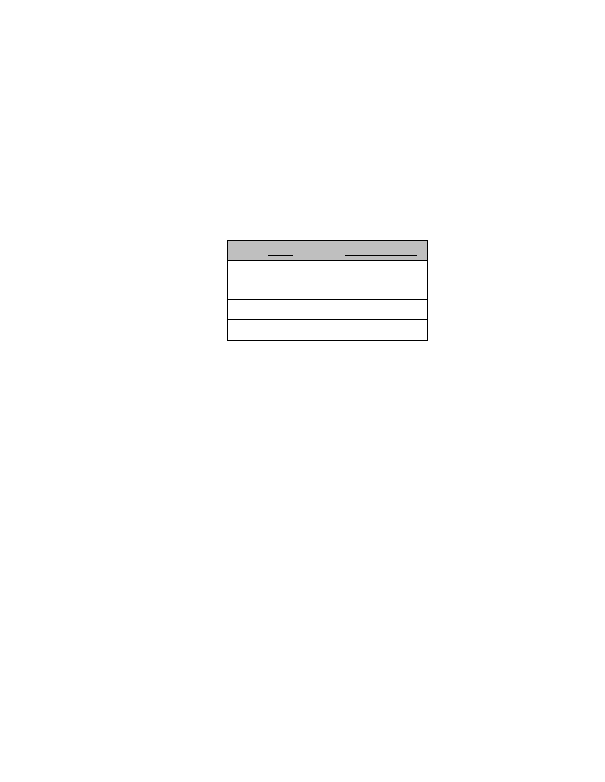
Data Packet Collection
1. Decide which extensions to use for each instrument.
Instrument Ext.
Digital handset ‘A’ − call forward to Atlas AVM
(made to be busy; no answer; etc.)
Digital handset ‘B’ − instrument that calls handset ‘A’
Digit grabber
2. To learn of a ‘forward busy’ event:
3.
Program digital handset ‘A’ to call forward to the extension that the
digit grabber is attached to (the pseudo Atlas AVM machine).Take
digital handset ‘A’ off-hook and create a busy (press intercom).
4.
At digital handset ‘B’ dial digital handset ‘A.’ The telephone system
will attempt to connect this call to handset ‘A’ but will not be able to
because of the busy state. Because handset ‘A’ is programmed to
‘forward calls on busy’ to the extension that is our 2500 handset
(Atlas AVM), the telephone system will then forward the call to that
extension. When the telephone system does the transfer of the call it
will also send along a data packet.
5.
When the 2500 set rings, pick up the handset.
6.
At the digit grabber, read the incoming data packet.
Page 42

4-18 Atlas AVM Installer’s Manual
7. To learn of the other events do the same basic procedure except
☞
Note
In-band data packet
information can also be
seen on the AVM
Diagnostic Trace
screens.
recreate the other telephony scenarios (e.g., no answer, disconnect, CO
line call, retrieve message, Atlas AVM initiating a call, etc.).
8.
Document what you learn on the Integration Form.
Page 43

Designing the Atlas AVM System
After you have determined that you can integrate with the customer’s
telephone system, you should work with a company representative to draw
up a basic design for the Atlas AVM system. This will help you in several
areas:
• Finding out what type of system the customer wants so you can begin
to put it together.
• Closing the sale. Giving the customer a more complete picture of what
Atlas AVM can do for them helps to secure the sale.
• Determining the Atlas AVM system size required by the company.
You made an estimate of how many boxes this company will need in
the evaluation phase. Now you need to come up with a more accurate
count.
5
Planning the Basic Design
Considerations for designing a system are outlined below.
1.
Design how the Auto Attendant will handle calls. This includes:
Primary or Secondary Auto Attendant—The Auto Attendant
answers all incoming calls, or a live operator answers calls
except when all calls cannot be accommodated by the operator.
Greetings—which can be set for different times (e.g. business
hours vs. non-business hours), days, or ports.
Caller Options—which give callers options for transferring from
the Auto Attendant box to an extension, the operator, or another
audiotext box. Callers also hear caller options when they enter
an invalid digit or fail to respond to a voice prompt.
2. Planning audiotext boxes. This includes the following:
Mapping the levels of audiotext boxes—which are designed to
allow callers to transfer from one audiotext box to another.
Page 44

5-2 Atlas AVM Installer’s Manual
Planning audio menus—which are the transfer options callers
hear in audiotext boxes.
3. Find out what the customers want their greeting and other audiotext
boxes to look like.
Help the customers determine what they want their system to
sound like.
Create some rough scripts based on the customer’s responses.
4. Planning individual voicemail boxes. This includes:
Obtaining a list of extension numbers of the people who will be
using the Atlas AVM system.
Deciding which range of Atlas AVM boxes to use for voicemail
boxes.
Renumbering the Atlas AVM boxes to match the extension
numbers of their owners.
After you have mapped out the basic design of the system, you should
know approximately how many total boxes are required for the Atlas
AVM system.
Sizing the System
The size of the Atlas AVM system purchased is based on the number of
boxes the company needs. Atlas AVM systems are available in the
following box group sizes:
50, 300, 500, 750, 1000, 2500, 5000, 7500, 10,000
Calculate the number of boxes based on the basic design of the system,
allowing for modifications or growth.
You also need to determine the number of ports and the disk space
required for the system. Use the Erlang Table and the following
worksheets:
• Auto Attendant
• Audiotext Calls
• Voicemail
• Ports Required
• Voice Storage
• Voice Storage Required
Page 45

Designing the Atlas AVM System 5-3
Erlang Measurement
Erlang is a unit of measurement for telephone traffic. (Total call seconds
per hour divided by 3600 equals an Erlang.) The Erlang measurement is
used to ensure that Atlas AVM is sized large enough to minimize the
number of blocked calls (busy signals) during the peak hours of calls.
Because all calls that come into a system are not evenly dispersed, you
cannot merely estimate the number of call seconds and then plug that
number into a chart. The Erlang measurement accounts for calls that are
concentrated in the same time period (i.e. overlap).
Use the Erlang Table when you fill out the Ports Required worksheet to
determine the number of ports needed. Blockage levels of 2% to 3% are
acceptable.
Page 46

5-4 Atlas AVM Installer’s Manual
Blockage
Number
Levels Number
of
Ports 10% 5% 3% 2% 1% 0.1% Ports
1 0.01 0.05 0.02 0.01 0.01 0.00 1
2 0.54 0.36 0.22 0.15 0.10 0.10 2
3 1.14 0.85 0.59 0.45 0.35 0.19 3
4 1.84 1.45 1.07 0.86 0.70 0.44 4
5 2.59 2.11 1.62 1.35 1.13 0.76 5
6 3.38 2.81 2.23 1.89 1.61 1.14 6
7 4.20 3.55 2.88 2.48 2.15 1.58 7
8 5.04 4.32 3.55 3.10 2.72 2.05 8
9 5.89 5.10 4.26 3.74 3.32 2.55 9
10 6.76 5.91 4.98 4.42 3.94 3.09 10
11 7.64 6.72 5.72 5.11 4.59 3.65 11
12 8.53 7.55 6.48 5.82 5.25 4.23 12
13 9.42 8.39 7.25 6.54 5.93 4.83 13
14 10.33 9.24 8.04 7.28 6.63 5.44 14
15 11.24 10.10 8.83 8.03 7.34 6.07 15
16 12.15 10.97 9.63 8.79 8.06 6.71 16
17 13.07 11.84 10.44 9.56 8.79 7.37 17
18 13.99 12.72 11.26 10.33 9.53 8.04 18
19 14.92 13.60 12.09 11.12 10.28 8.72 19
20 15.86 14.49 12.92 11.91 11.04 9.40 20
21 16.79 15.38 13.76 12.71 11.80 10.10 21
22 17.72 16.28 14.60 13.51 12.57 10.80 22
23 18.66 17.18 15.45 14.32 13.35 11.51 23
24 19.61 18.08 16.30 15.14 14.13 12.23 24
25 20.55 18.99 17.15 15.96 14.92 12.96 25
26 21.50 19.90 18.02 16.79 15.72 13.69 26
27 22.45 20.81 18.88 17.62 16.52 14.42 27
28 23.40 21.72 19.75 18.45 17.32 15.17 28
29 24.35 22.64 20.62 19.29 18.13 15.91 29
30 25.30 23.56 21.49 20.13 18.94 16.67 30
of
31 26.26 24.48 22.37 20.98 19.75 17.42 31
32 27.21 25.41 23.25 21.83 20.57 18.19 32
33 28.17 26.33 24.13 22.68 21.40 18.95 33
34 29.13 27.26 25.02 23.54 22.22 19.72 34
35 30.09 28.19 25.91 24.39 23.05 20.50 35
36 31.05 29.12 26.80 25.25 23.89 21.27 36
37 32.02 30.06 27.69 26.12 24.72 22.06 37
38 32.98 30.99 28.58 26.98 25.56 22.84 38
39 33.94 31.93 29.48 27.85 26.40 23.63 39
40 34.91 32.86 30.38 28.72 27.24 24.42 40
Figure 5 -1: Erlang Table
Page 47

Designing the Atlas AVM System 5-5
1.
2.
3.
4.
5.
6.
7.
8.
9.
10.
11.
12.
13.
14.
Auto Attendant
AA = Auto Attendant
VR = Voice Response (calls coming back to the Auto Attendant)
______ Number of calls to the Auto Attendant during peak hours
x ______ Length of prompts for AA (in seconds)
= ______ AA seconds per hour
______ VR calls
x ______ Average VR time (in seconds)
= ______ VR seconds per hour
______ AA seconds per hour (from line 3)
+ ______ VR seconds per hour (from line 6)
= ______ Total call seconds per hour for the Auto Attendant
(AA + VR)
Audiotext Calls
______ Number of audiotext calls per peak hour
x ______ Number of boxes listened to during a call
= ______ Number of calls and boxes
x ______ Length of average audiotext message (in seconds)
= ______ Total call seconds in peak hour for audiotext
Page 48

5-6 Atlas AVM Installer’s Manual
______
______
______
______
______
______
______
______
Voicemail
Message Calls (leaving a message)
15. ______ Number of employees
16. x
17. =
18. x
19. =
20. /8
21. =
______ Number of messages per day per employee
______ Total message calls per day
Length of entire message sequence (in seconds)
(prompts + messages + editing)
______ Total message call seconds per day
______ Hours in business day
______ Message call seconds per hour
Subscriber Calls (listening to messages)
22.
23. x
24. =
Number of employees
Number of calls per day to check messages
Total subscriber calls per day
25. x
26. =
27. /8
28. =
Length (seconds) of a subscriber call
Total subscriber call seconds per day
Hours in business day
Subscriber call seconds per hour
Ports Required
Step 1: Add the following lines from the previous worksheets
Line 9, Auto Attendant ______
Page 49

Designing the Atlas AVM System 5-7
1.
2.
3.
4.
5.
6.
7.
8.
Line 14, Audiotext ______
Line 21, Message calls
Line 28, Subscriber calls
Total ______
Step 2: Take the total from Step 1 and divide it by 3600 to determine the
Erlang number. Go to the Erlang Table and find the line closest to that
number in the 2% to 3% blockage range. Find the number of ports
associated with that line and enter it here.
Total Ports Needed
Voice Storage
1 hour of voice storage = 10 MB of disk storage
Voicemail
______
______
______
______
______ Numbers of employees
x ______ Number of messages left per employee per day
= ______ Total messages per day
x ______ Length (seconds) of messages left by callers
= ______ Total seconds of voicemail storage per day
Audiotext
______ Length (seconds) of average audiotext message
x ______ Number of audiotext boxes
= ______ Total seconds for audiotext messages
Page 50

5-8 Atlas AVM Installer’s Manual
Voice Storage Required
Step 1: Add the following lines from the Voice Storage worksheet:
Line 5, Voicemail ______
Line 6, Audiotext ______
Total = ______
Step 2: Divide the total from Step 1 by 60 (i.e. minutes divided
by seconds)
Total = ______
Step 3: Divide the total from Step 2 by 60 (i.e. hours divided by
minutes)
Total = ______
Step 4: If 1 hour of voice storage = 10 MB of disk storage
Then ____ hours of voice storage (Step 3) =
Plus 10 MB for the Atlas AVM files =
Total Disk Storage Needed
÷ 60
÷ 60
______ MB of disk
storage
+ 10 MB for
Atlas AVM
______
Page 51

Installing Voice Boards
Understanding Voice Boards
Voice boards perform the following functions:
• Digit Processing: detecting and generating DTMF tones
• Voice Processing: playing and recording messages
• Call Processing: listening for and characterizing tones and
frequencies, and reporting them back to Atlas AVM
Atlas AVM can use certain voice boards manufactured by Dialogic and
Rhetorex. These boards and their setup are described in sections of this
chapter and in Chapters 7 and 8. Read the material that applies to the
voice boards used in your system.
6
Voice Board Installation
Unpacking and Handling the Boards
Before you unpack your voice boards, make sure you have a clear, clean,
dust-free space to work.
Printed circuit boards can be damaged easily if subjected to rough
handling or electrostatic conditions. Wear an anti-static wrist strap and use
electrostatic-dissipative mats whenever you handle PC boards.
Installing the Voice Boards
See Chapters 7 and 8 for setup and strapping options for your voice
boards.
When all boards have been prepared, follow the instructions below to
install them in the PC:
1.
Unplug the power cords to the PC and to any connected peripheral
devices.
Page 52

6-2 Atlas AVM Installer’s Manual
2. Remove the PC cover and set it aside, along with the screws, in a safe
place.
☞
Note
If you are installing a
one-board system it is
recommended that you
install the voice board
in the slot that is
farthest away from the
power supply. If
there is more then one
board in your system,
install the number one
board in the slot
farthest from the
power supply, the
number two board in
the slot next to the
number one board,
3.
Remove the first voice board from its anti-static bag. Set the jumpers
according to the information in Chapters 7 or 8.
4.
Slide the board into the slot farthest from the power supply, seating it
firmly in the connector strips.
5.
Tighten the screw connecting the board to the chassis. (This grounds
the board.)
6.
Remove the second board (if any) from its anti-static bag and install it
in the slot next to the number one board. Repeat for all remaining
boards.
7.
When all boards have been installed in their proper slots, return the
cover to the PC and attach it securely.
8.
Reattach all power cords and power up the PC and any peripheral
equipment.
☞
Note
RJ-11 and RJ-14
jacks look similar;
however, RJ-11s
provide only one line
while RJ-14s provide
Attaching the Cables
To attach the voice boards to the telephone system, follow the instructions
below.
Insert a plug into the jack in the rear bracket of the voice board. There is a
snap or click when the plug is properly connected.
Continue to connect the RJ-11 or RJ-14 plugs to all the voice boards.
Page 53

Dialogic Voice Boards
The Dialogic voice boards that you can use with your Atlas AVM system
include those shown in Table 6 -1.
Installing Voice Boards 6-3
Model Ports Comments
D/41E 4 2 each/RJ11
D/41D 4 2 each/RJ14
D/41SX 4
D/41SL 4 2 each/RJ14
D/41NS 4 4 each/RJ11
D/121B 12 Must work with
LSI/120
LSI/120 12 DB25
Table 6 -1: Dialogic Board Specifications
D/41E
A 4 port digital store-and-forward voice board with world approvability,
access to resource modules, and additional power for future firmware
features.
D/41D
Board Jack
2 each/RJ14
NA
A 4 port digital board used to connect to single line station ports from a
PBX or telephone company. Typical 2500 telephone interface, i.e.
Centrex/SMDI, loop station interface.
D/41SX
A 4 port digital board used with the Mitel PBX using COV or Super Set
integration.
D/41SL
A 4 port digital board used with the Northern Telecom SL-1 PBX using
SL-1 station integration.
D/41INS
A 4 port digital board used with the NorStar TCM digital station interface.
Page 54

6-4 Atlas AVM Installer’s Manual
D/121B-LSI/120
Used together to give 12 ports – same as the D/41D but supports 12
analog ports.
Basic Analog Configuration
The D/41D board contains everything needed for the basic 4-port analog
configuration. Higher density 8-port and 12-port boards use a SpringBoard
connected via PEB cable to an LSI board.
The basic 12-port analog application uses a D/121B board connected via a
PEB cable to one LSI/120 board. This configuration will handle up to 12
telephone lines. A PEB terminator must be installed on both the voice
board and the LSI/120.
Multiple Board Configurations
The number of boards that can be used in a system varies according to the
type of boards in use and the number of free slots available in the PC.
Each D/41D board requires one 8-bit slot. D/121B and LSI/120 boards
must be used together, requiring two 8-bit slots per set.
Page 55

Installing Voice Boards 6-5
T2 T1 R1 R2
RJ14
D/41D
RJ14
RJ14
T R
RJ-11
D/41NS
RJ11
RJ11
RJ11
RJ11
D121/LSI/120
DB25
Pin Term. Pin Term.
Dialogic Telephone Connectors
1
2
3
4
5
6
7
8
9
10
11
12
Figure 6 -1: Cord Connections for Dialogic Boards
T1
R1
T2
R2
T3
R3
T4
R4
T5
R5
T6
R6
13
14
15
16
17
18
19
20
21
22
23
24
25
T7
R7
T8
R8
T9
R9
T10
R10
T11
R11
T12
R12
Page 56

6-6 Atlas AVM Installer’s Manual
T2 T1 R1 R2
RJ14
RJ14
D SUB
432/2132/4132/9432
Rhetorex Voice Boards
The Rhetorex voice boards that you can use with your Atlas AVM system
include those shown in the following table.
Models Card Size Ports Jack/Connection
208 Duet Half 2 1 each – RJ14
408 Quartet Half 4 2 each – RJ14
432 / 232 Half 4 2 each – RJ14
2132 Full 2 1 each – RJ11
4132 Full 4 2 each – RJ14
9432 Full 4 2 each – RJ14
Table 6 -2: Rhetorex Board Specifications
Rhetorex Telephone Connectors
15 Pin
Figure 6 -2: Rhetorex Telephone Connectors
RDSP/432
A 4 port, analog, half length board that supports 4 analog telephone
interface ports.
RDSP/208
A 2 port, analog, half length card. This board supports 2 analog single line
telephone interface ports. Only one board allowed per system.
Page 57

RDSP/408
A 4 port, analog, half length card. This board supports 4 analog single line
telephone interface ports. Only one board allowed per system.
RDSP/2132
A 2 port, analog board that supports 2 analog telephone interface ports.
RDSP/4132
A 4 port analog board that supports 4 analog telephone interface ports.
RDSP/9432
A 4 port analog board that is internationally approved. It supports 4 analog
telephone interface ports.
Call Progress Tones
Your telephone system uses audible tones to indicate the progress of a
call. These call progression tones include four basic tones:
Installing Voice Boards 6-7
☞
Note
Although silence is not
considered a tone, it is
also recognized and
acted on by the voice
board.
• dial tones
• busy tones
• ring tones
• reorder tones
Dial tone: This tone tells the caller that the central office or the telephone
system is ready to receive address signals (i.e. telephone number or
extension).
Busy tone: This tone indicates that the number being called is busy.
Ring tone: When a caller places a call, a ring tone is returned to the caller.
This ring tone, also called a ring back, indicates that a path has been
established and the called instrument is being rung.
Reorder tone: The tone that sounds when a telephone has been left off
hook longer than the maximum length of time.
By listening to the call progression tones, a caller can recognize the state
of a call. Similarly, the voice board can listen to call progression tones and
recognize the state of a call. However, there is no standard way for a
telephone system to express these tones. Consequently, the specific tone
characteristics used by the telephone system must be defined in order for
the voice board and driver to integrate with the telephone system.
Page 58

6-8 Atlas AVM Installer’s Manual
Tone Characteristics
Tone characteristics relate to three main areas:
Frequency: The number of vibrations, or oscillations, per time unit of an
alternating current.
Duration: The complete signal sequence consisting of ‘on time’ (the
signal) and ‘off time’ (silence).
Cadence: The length of the ‘on time’ and the length of the ‘off time’ in a
one tone cycle.
These three tone characteristics (frequency, duration, cadence) must be
determined for each of the four call progress tones (dial tone, busy tone,
ring tone, and reorder).
The driver can recognize a tone if the tone’s characteristics match the
parameters for a tone in the tone table.
Utility programs such as Call Analysis for Dialogic or AccuCall Plus for
Rhetorex, allows users to determine, test and define the frequency,
duration and cadence elements of the environment’s call progression
tones.
Supervised Transfers
If the telephone system does not provide in-band signaling (i.e., data
packets), then Atlas AVM will have to supervise all its transfers in order
to ascertain the result of those transfers (e.g., busy, no answer, etc.). This
is called a ‘supervised’ transfer. Atlas AVM must therefore be able to
accurately understand the tones the telephone system uses to denote these
different events, which are called ‘call progress tones.’ This is done by
building a database file of the characteristics of a particular telephone
system’s call progress tones.
The following is an example of a supervised call:
1. An outside call comes into a PBX. The PBX is programmed to send
all calls to Atlas AVM.
2. Atlas AVM plays the port greeting for the caller and prompts the
caller
to enter the desired extension.
3. The caller enters the number 100.
4.
Atlas AVM looks in its voicemail box configuration database for box
100. It transfers the call to extension 100.
5.
Atlas AVM attempts to transfer the call to extension 100. It does this
by signaling (e.g., flash hook then extension number) the telephone
Page 59

Installing Voice Boards 6-9
system to transfer the call to extension 100. (At this point the outside
caller is ‘parked’ at the telephone system.)
6.
Since this telephone system does not use in-band signaling (i.e., no
data packets), Atlas AVM is going to ‘stay on the line’ during the
transfer in order to learn the result of this transfer.
7.
In this case, extension 100 is busy. The telephone system sends a
particular tone to denote a busy event.
8. Atlas AVM, which is still ‘listening on the line,’ references its tone
table to see what this tone denotes
9. Once Atlas AVM realizes that extension 100 is busy, it looks in its
voicemail box configuration database for what to do when extension
100 is busy
10.
Atlas AVM then connects back to the parked call and plays the user’s
box greeting for voicemail box 100. The caller can then leave a
voicemail message.
−in this case, take a message.
.
☞
Note
Begin these steps
before you have
installed the Rhetorex
voice board in the
computer. You will be
installing the board in
the third step.
For step 8 to work, a tone table must be created for this particular
telephone system. One way to do this with a Rhetorex voice board is to
use the program AccuCall Plus.
AccuCall Plus (Rhetorex only)
AccuCall Plus is a program developed by the vendor Rhetorex. This
program can be used with a Rhetorex voice board to analyze the tone
characteristics of a particular telephone system.
In this regard, it is like a protocol analyzer in the data communication
field, except that AccuCall Plus analyzes tone characteristics.
AccuCall Plus can analyze the tone characteristics for each of the call
progress events (e.g., dial tone, busy tone, ring tone). AccuCall Plus then
puts the information on the specific tone characteristics into a tone table
(i.e., a database file). This tone table can then be referenced by the
Rhetorex driver and Atlas AVM.
Installation and Use of AccuCall Plus
AccuCall Plus is a DOS executable program. It must be run on the PC that
will have the Rhetorex voice board in it. Follow the steps below to run
AccuCall.
Copy files (from AccuCall Plus disk).
1.
MD c:\rhetorex
2.
COPY a:\*.* c:\rhetorex
Page 60

6-10 Atlas AVM Installer’s Manual
View graphical depiction of possible voice board
configurations.
1.
\rhetorex\SHOWJUMP.EXE
Explanation: This utility shows you a graphical depiction of the
board settings for different configuration options. You must pick a
setting that will not conflict with the other devices in the machine
being used to run AccuCall Plus, and ultimately that does not
conflict with anything in the Atlas AVM computer. Please refer to
the Server Configuration Worksheet for the configurations already
in use by your Atlas AVM computer.
Write down the configuration parameters and the matching board
settings.
Install the voice board.
1.
Set the switches on the voice board to match your chosen
configuration.
2.
Turn off machine.
3. Install board in machine. (To reduce interference, put the voice board
in an expansion slot that is not near the power supply.)
4. Attach single-line analog lines into the ports of the voice board.
Configure AccuCall Plus to match the voice board.
1.
Turn on machine
2.
At the DOS-prompt, type: cd\rhetorex
3.
CONFIGUR.EXE
Explanation: Set the following parameters to match the voice
board.
Port = _____ (also called I/O memory address)
DualPort =_____ (also called base memory address)
Entry point = _____
Execute the Rhetorex DOS driver.
1.
Type: c:\rhetorex\rhetdrv.exe
When the driver has successfully loaded, a log file called
voicecnf.log will be displayed on the screen. The information
shown covers ports, channels, status, serial number, number of
voice boards found, number of channels, memory allocation,
firmware level, revision, and date.
If voicecnf.log does not come up (if it hangs), then rename
CONFIG.SYS and AUTOEXEC.BAT and reboot the machine.
Page 61

Installing Voice Boards 6-11
Execute AccuCall Plus.
1.
Type: cd\rhetorex\accucall.
2.
Press <F6> to do an auto-run.
3.
Enter the extension number you want AccuCall to call.
4.
Make that target extension busy by going off-hook.
5.
Press <F9> to start the AccuCall analysis of the tone characteristics.
6.
When the cycle is completed, it will prompt you to press <F8>.
7.
Enter a name to describe the tone characteristics it has just analyzed,
e.g. busy.
8.
Select the event type by pressing <spacebar>, and then busy.
9. Arrow down to PCPMCODE and enter the number 7. This is the
Rhetorex code for a busy event.
10. Press <F8> to add the preceding information to the table.
11.
Press <F10> to return to the main menu.
12.
Repeat letters c through h for a ‘ring no answer’ event. Its
PCPMCODE code is the number 8.
13.
Press <F7> to give a name to the tone table you have just created.
Give it a descriptive name, e.g., COMDIAL.TON.
14.
Press <F8>to save the tone table.
15.
Press <F10 to save the tone table to a disk and exit.
For a complete AccuCall manual Please contact Rhetorex or
Key System US
Page 62

6-12 Atlas AVM Installer’s Manual
This page intentionally left blank.
Page 63

Building the System
Environmental Considerations
The following environmental conditions are recommended:
• Operating temperature: 0 to 50 °C
• Humidity: 8% to 80% non-condensing
• Storage temperature for voice boards: -10 to 70 °C
Refer to your PC and voice board owner’s manuals for specific
recommendations.
7
Power Supply Considerations
Voicemail system customers are responsible for obtaining appropriate
power backup equipment for their systems. The Atlas AVM manufacturer
recommends use of an Uninterruptible Power Supply unit (UPS).
The UPS is a battery backup system that ensures continuous operation for
the voice messaging system during periods of minor AC power
irregularity. In the event of a power loss of longer duration, some UPS
units can initiate a graceful shutdown of the system so that no data is lost.
The capacity of the UPS unit required can vary with the number of pieces
of equipment to be protected, the current drawn by such equipment, the
desired duration of battery backup power, and other factors. The customer
is responsible for ensuring that the capacity of the UPS unit is sufficient to
provide the required protection.
Not all UPS units provide surge protection. The Atlas AVM manufacturer
recommends the use of a UPS unit that provides this feature.
Page 64

7-2 Atlas AVM Installer’s Manual
Hardware Specifications
Certain hardware specifications and configurations are required before a
PC can be utilized for Atlas AVM voice processing.
Component 4-12 Port System 16-20 Port System 24 Port System
CPU 386, 486DX, or
Pentium – Intel
RAM 4 MB 8 MB 12 MB
Bus ISA ISA ISA
Speed 25-66 MHz or better 33-66 MHz or better 66 MHz or better
Hard drive IDE or SCSI IDE or SCSI IDE or SCSI
BIOS AMIBIOS AMIBIOS AMIBIOS
Power supply 200 watt UL approved 250 watt UL approved 300 watt UL approved
Figure 7-1: Minimum Hardware Specifications
Note: The maximum number of ports for an Atlas AVM system is 64.
486DX to Pentium –
Intel
486dx2 to Pentium –
Intel
☞
Device/Port Usage IRQ Address
Serial Port (COM1) SMDI Serial Integration 4 3F8H
Serial Port 2 (COM2) Modem 3 2F8H
Serial Port 3 (COM3) DISABLED N/A N/A
Serial Port 4 (COM4) DISABLED N/A N/A
Parallel Port 1 (LPT1) Hardware Lock/Printer 7 378H
Parallel Port 2 (LPT2) DISABLED N/A N/A
Game Port (If on I/O Card) DISABLED N/A N/A
Voice Board Call Processing 5 D000*
(memory address)
Video Board Display N/A N/A**
Figure 7-2: Suggested Hardware Configuration
Page 65

*The first voice board should be set to base memory address D000H and
offset 0H. Each board requires a total offset of 200H. So, for a two board
installation, the first should be set at address D000H-D1FFH and the
second should be set at address D200H-D3FFH.
**The video card memory and BIOS must not conflict with the voice
board. Most video cards do not access memory above BFFFH, but the
BIOS shadowing can create problems if an attempt is made to shadow into
the voice board’s address segment. This is true for system and other BIOS
shadowing as well as other reserved areas of memory like the EMS page
frame.
It is recommended that you provide a 9600 baud modem (or higher) for
maintenance and remote support.
Hard Drive Size
Building the System 7-3
Voicemail
☞
Note
10 Mb equals
approximately 55
minutes of voice
storage
Hours of
Users
25 2 2 port/ 2 hour 100 MB
100 5 4 port/ 10 hour 200 MB
250 12 8 port/ 12 hour 250 MB
500 25 16 port/ 25 hour 500 MB
Storage
Figure 7-3: Recommended Hard Drive Size
Recommended
Size
Hard Drive
Size
Page 66

7-4 Atlas AVM Installer’s Manual
This Page Intentionally Left Blank.
Page 67

Connecting Atlas AVM to a
Telephone System
Since voicemail is an add-on component, it is dependent on the telephone
system for all integration features. Some telephone system manufacturers
have programmed their systems to work well with voicemail. Some,
however, have made their systems work only with certain voicemail
systems (they sell a specific voicemail system with their telephone
☞
Note
Remember—if a single
line telephone (2500
set) can do it, so can
the Atlas AVM.
system), and some manufacturers have done nothing to enhance their
systems.
This chapter explains alternatives to achieve the best possible integration
your telephone switch can provide.
Some telephone systems may be cumbersome to operate or cause users to
do extra functions in order to achieve their goals, but the main objective is
to ensure that all voicemail features possible are available to users.
8
Telephone System Integration Definitions
These definitions explain the references in the Atlas Telephone System
Compatibility Listings.
Full Integration
Call forward station to personal greeting
Message waiting indication on telephone set
Call transfer to attendant or any extension
Outdial notification
Partial Integration
Call forward station to generic greeting (customer to enter mailbox
number)
May or may not have message waiting indication on station
Call transfer to attendant or any extension
Outdial notification
Page 68

8-2 Atlas AVM Installer’s Manual
Data Link
RS232
Restricted Integration
Call forward station to generic greeting (customer to enter mailbox
number)
No message waiting
No transfers allowed
No outdial notification
All other features, like group messages, date and time stamp etc. are
dependent on the voicemail system.
Integration Types
There are many types of integration that are designed to offer the most in
voicemail features. Listed below are some ways to achieve this.
Serial Integration
This is where the telephone system or C.O. is connected to the voicemail
unit via an RS232 link which passes call party information. This type of
integration offers all available voicemail features.
C.O./Telephone
Single Line
Ports
RS232
Figure 8-1: Example of Serial Integration
Atlas AVM
Analog
Ports
Voice
Board
Page 69

Telephone
System
Single Line
Ports
Digital
Port
Connecting Atlas AVM to a Telephone System 8-3
Serial Integration with Additional
Equipment
Atlas AVM
RS232 D
Data LinkDecoding Unit/Voice Bridge
Figure 8-2: Serial Integration with a Voice Bridge
The voice bridge unit gives the customer a full featured system by
hooking up to an electronic station and “reading the screen.” The voice
bridge then converts this information to SMDI protocol and sends the call
data over the RS232 link to the voicemail system. The voice bridge unit is
used on the AT&T system 75/85, Rolm CBX and Northern Telecom SL-
1.
In-band integration: In this type of integration voicemail is connected to
the telephone system via voice lines. The telephone system passes data via
DTMF keys, giving the voicemail information about the type of call that it
is handling. For example:
• The telephone system rings voicemail.
• Voicemail goes off-hook.
• The telephone system sends DTMF keys stating:
Call type
Calling Number
Called Number
This enables voicemail to know what to play with each call. The personal
greeting, company greeting or auto attendant greeting. This type can offer
some or all features, depending on the sophistication of the telephone
system.
Page 70

8-4 Atlas AVM Installer’s Manual
C.O.
Figure 8-3: Example of In-Band Integration
Telephone System
Incoming
Ports
Possible Integration Features
Due to the many telephone systems on the market today, it would be
impossible to show every connection and program setting available.
Below is a list of features given as a reference for you to investigate every
possible means of connecting Atlas AVM to a telephone system.
Single
Line
Ports
Atlas AVM
Voice
Boards
Voice Connections
This entails having a voice channel from the telephone system to Atlas
AVM.
Using a Single Line Station: This is a typical way for Atlas AVM to
interface with a telephone system. It offers a talk path that generally can
hook flash transfer a caller. DTMF is dependent on the calling extension.
The telephone system may allow turning on and off a message waiting
indicator.
Using an OPX port on a hybrid system: Most telephone systems that offer
OPX ports have the same privileges as a single line set.
Call Transfers
The telephone system has the ability to hook flash and dial an extension
and hear ring back, busy or error tones.
Single line ports usually allow hook flash transfers to the attendant or any
extension.
OPX ports usually allow hook flash transfers, but be cautious of
transferring on intercom paths. Check to make sure multiple calls can
transfer to actual stations and not just light up an intercom path.
Page 71

Connecting Atlas AVM to a Telephone System 8-5
Outdials
The telephone system must have at least one port to do outdials on. This
could be a single line telephone port from the telephone company which
would be used for outdial notification.
Call Forward to Personal Greeting
A station user can forward a telephone to Atlas AVM and have it play the
box owner’s personal greeting.
The telephone system can forward a station to a voice port, then pause,
wait for answer, then out pulse DTMF digits (the called extension).
The telephone system can forward a station to a speed dial number (bin).
That speed dial dials the voicemail extension, pauses, then out dials
DTMF digits (the called extension).
Depending on its capabilities, the telephone system may be able to
forward a station off-premise. This allows you the ability to forward to a
trunk, pause, then outdial the called extension number. This is usually
done by taking the tip and ring from an out-going loop-start trunk and
tying it down on a single line extension number. When the trunk is seized
you get internal dial-tone instead of C.O. dial tone. Then you dial the
voicemail number, pause, and dial in the called extension number. You
hear the personal greeting.
Message Waiting Indication
The telephone system allows a voicemail port to dial an access code, then
the extension number, in order to light a message waiting light.
The availability of this feature is totally dependent on the telephone
system. Atlas AVM turns on and off the message waiting light by going
off hook, dialing a feature code, then the extension number with the
message, and going back on hook.
Page 72

8-6 Atlas AVM Installer’s Manual
This Page Intentionally Left Blank.
Page 73

Integrating with the Telephone
System
System Default Configuration
The Atlas AVM system comes on-line using default parameters that
work with a Standard Telephone System. This means that if you are
connecting the system to analog single line station ports and the
telephone system uses North American standards for ringing, tones and
hook-flash intervals, you may not need to make any changes listed in
this chapter.
9
Follow the instructions in this chapter only if you wish to modify some
integration information. Check specifically the parameters concerning:
• Message Waiting Light/Indicator
• In-Band Data Packets
• Call Transfer Sequence
If your system is standard please go to the System Administrator’s
Manual to set up mailboxes and record greetings. You need not make
any changes in this section.
For non-standard types of telephone systems, refer to the individual
document for that specific telephone system in the Atlas Telephony
Integration Guide. Go through all of the integration screens in this
chapter and modify them to match your telephone system.
Refer to the specific sections in this chapter, or call Key System US
Technical Support Services if you need help completing your telephone
system integration.
Key System US Technical Support Services
(800) 833-3446
8:30 A.M. to 5:00 P.M. Eastern Standard Time
Monday through Friday (excluding holidays)
24hr technical support is also available upon request.
Page 74

9-2 Atlas AVM Installer’s Manual
Understanding the Integration Screens
Parameters
The screens in this manual are shown with the field default parameters.
☞
Note
Port and global
parameters should only
be changed under the
direction of a qualified
Atlas AVM installer or
technician.
Each field description explains the type of data to be entered, including
range and resolution if necessary.
Voice Board Considerations
Some of the integration parameters must be set according to what type of
voice board you are using in your Atlas AVM system. When that is the
case, the screens for both Dialogic and Rhetorex voice boards are shown
in this manual. Read the information that pertains to your voice board
type and disregard the information for other types.
Accessing the Integration Screens
This section will walk you step by step through the installation screens.
Use this section for full explanations of all screen languages and system
defaults.
Access to the Atlas AVM integration screens is limited to authorized
Atlas AVM installers. Entering the installation passcode (default is
Atlas) at the Main Status screen allows access to all screens, including
the Integration screens. Entering the administration passcode (default is
1234) does not provide access to the Integration screens.
The installation passcode can be changed in the Administration General
Parameters menu if accessed using the installation passcode. If the
menus are accessed using the administration passcode, the installation
passcode is not displayed and cannot be changed.
Do not give the installation passcode to system administrators or other
unauthorized personnel. Attempting to change, set, or reprogram
integration field information by unauthorized personnel could cause the
system to malfunction.
From the Main Status screen, press <F10>. The passcode entry box
appears, where you must enter the default installation passcode —Atlas.
During programming please change this passcode and guard it. Damage
to the system can occur if values are changed improperly.
Page 75

Integrating with the Telephone System 9-3
Figure 9-1: The Passcode Entry Box on the Main Status Screen
After you have entered the correct passcode, the System Administration
Menu appears where you can select integration options.
Figure 9-2: The System Administration Menu
The two Integration options are Global and Port.
The Global Parameters screens set duration and control parameters for
all channels on the voice board.
Page 76

9-4 Atlas AVM Installer’s Manual
The Port Parameters screens set duration and control parameters for
individual channels on the voice board.
Global Parameters
Select Integration➞Global➞Edit to access the Edit Global Telephone
Parameters screens.
Figure 9-3: Global Options
The Global Parameters screens differ depending on which type of voice
boards you have.
The following screens and panels are available under Integration➞
Global➞Edit
Edit Global Parameters Screen 1
• Telephone System
• Dialogic Control Block or Rhetorex Global Parameters
• Control (Dialogic only)
Edit Global Parameters Screen 2
• Serial Port
• Integration Control
Edit Global Parameters Screen 3
• Serial Packet Separation (4 screens)
Page 77

☞
Note
The Rhetorex Global
Parameters panel is
shown on page 9-9.
Integrating with the Telephone System 9-5
The Edit Global Parameters Screen 1
The first screen that appears is Edit Global Parameters Screen 1. This
screen contains the Telephone System panel, either the Dialogic Control
Block or the Rhetorex Global Parameters panel and the Control panel
(Dialogic only).
Figure 9-4: The Telephone System and, Dialogic Control Block
and Control Panels
Telephone System Panel
The Telephone System panel displays Standard Telephone System Type
as the default. Select your telephone system name, if it is available, from
the list that appears. If it is not available, use the default.
At this point, the default parameters for the telephone system you have
chosen are automatically loaded on the Edit Global Parameters screens.
Page 78

9-6 Atlas AVM Installer’s Manual
Dialogic Control Block Panel
Do not change any of these parameter settings unless instructed by a
technician.
flashchr
Flash Character: Character in the dialing string that causes a hook flash
to occur.
Length: 1. Default: &. Units: ASCII
digrate
Digitization Rate: Play/record digitization rate. Default play/record
digitization rate for the system. 6000 Hz or 8000 Hz on DSP voice
boards; 6053 Hz or 8117 Hz on non-DSP voice boards. On DSP voice
boards you can override digrate per channel by specifying the sampling
rate for the play/record function.
Length: 2. Default: 6000 (DSP voice boards) or 6053 (non-DSP voice
boards). Units: Hz.
p_mk
Pulse Make: Duration of the pulse dial on-hook interval.
Length: 2. Default: 4. Units: 10 ms.
oh_dly
Off-Hook Delay: Time delay that occurs after executing a channel offhook command. DTMF digits are not recognized while going off-hook.
If your application requires immediate DTMF, wink, or loop current
drop detection upon going off-hook, set oh_dly to 1.
Length: 1. Default: 50. Units: 10 ms.
r_ird
Ring Interring Delay: Maximum time between incoming rings. The ring
counter is reset after this time has expired; rings that occur after this
interval are considered the start of a new call cycle.
Length: 2. Default: 80. Units: 100 ms.
minpdon
Minimum Pulse Digit On: Minimum make interval to validate an
incoming loop pulse digit.
Length: 1. Default: 2. Units: 10 ms.
Page 79

Integrating with the Telephone System 9-7
minlcoff
Minimum Loop Current Off: Minimum time that loop current must be
off.
-1: Disable this condition.
Length: 2. Default: -1/ Units: 10 ms/
flashtm
Flash Time: Length of time on hook during a hook flash.
Length: 2. Default: 50. Units: 10 ms.
sch_tm
Scheduler Time: Maximum number of clock ticks in which to perform
scheduler activities.
Length: 2. Default: 20. Units: 1 clock tick (1/18 sec).
p_idd
Pulse Interdigit Delay: Delay between digits during pulse dialing.
Length: 2. Default: 100. Units: 10 ms.
r_on
Ring On: Minimum ring voltage on duration for an incoming ring.
Length: 2. Default: 3. Units: 100 ms.
s_bnc
Silence Debounce: Minimum time that silence must be present to
produce a T_SILON or T_SILOFF CST event.
minpdoff
Minimum Pulse Digit Off: Minimum break interval to validate an
incoming loop pulse digit.
Length: 1. Default: 2. Units: 10 ms.
maxpdoff
Maximum Pulse Digit Off: Maximum make interval to validate an
incoming loop pulse digit.
Length: 2. Default: 50. Units: 10 ms.
Pause Time: Delay caused by a comma (,) in the dialing string.
Length: 2. Default: 200. Units: 10 ms.
Page 80

9-8 Atlas AVM Installer’s Manual
p_bk
Pulse Break: Duration of the pulse dial off-hook interval.
Length: 2. Default: 6. Units: 10 ms.
t_idd
DTMF Interdigit Delay: Delay between digits during DTMF dialing.
Length: 2. Default: 5. Units: 10 ms.
r_off
Ring Off: Minimum ring voltage off duration for an incoming ring.
Length: 2. Default: 5. Units: 100 ms.
ttdata
DTMF Time Data: Duration of the DTMF digits in out-bound tone
dialing.
Length: 1. Default: 10. Units: 10 ms.
minipd
Minimum Interpulse Digit: Minimum time between loop pulse digits.
Length: 2. Default: 25. Units: 10 ms.
Control Panel
System start delay time
The system start delay time can be increased from the default, 0, to allow
time for the voice boards to load during start up.
If there are not enough ports displayed on the Port Status screen, it may
be that the voice boards did not have time to load and you should
increase the system start delay time. This is especially true for systems
with a high number of ports.
To increase the system start delay time, enter a number between 0 and 99
in this field.
Rhetorex Global Parameters Panel
The global parameters for Rhetorex voice boards are found below the
Telephone System panel on the Edit Global Parameters Screen 1.
Page 81

Integrating with the Telephone System 9-9
Figure 9-5: The Telephone System and Rhetorex
Global Parameters Panels
FlashChar
Flash Character: the character that causes a flash hook when dialing.
Usage: character. Use the default value–&.
PulseBreak
The duration of the break interval during pulse dialing.
Usage: Numeric, Units = 10 msec. Use the default value–6 (60 msec.)
DTMF Delay: the interval between DTMF digits during tone dialing.
Usage: Numeric, Units = 10 msec. Use the default value–5 (50 msec.).
When the HOST parameter in CONFIG is UK, the default value is 8 (80
msec.).
MinOff
(Minimum off–msec.) The minimum necessary duration of a valid
inbound ring’s on period.
Usage: Numeric, Units = 100 msec. Use the default value–5 (500 msec).
DtmfOn
The DTMF tone duration when dialing.
Usage: Numeric, Units = 10 msec. Use the default value–10 (100 msec.).
MinDigitSep
Minimum Digit Separation: the minimum necessary off period duration
for a valid loop pulse digit.
Usage: Numeric, Units = 10 msec. Use the default value–25 (250 msec.).
Page 82

9-10 Atlas AVM Installer’s Manual
MaxPulseOn
Maximum Pulse On: the maximum allowable on period for a valid loop
pulse digit.
Usage: Numeric, Units = 10 msec. Use the default value–50 (500 msec.)
FlashDur
Flash duration: the duration of the on–hook state during a flash hook.
Usage: Numeric, Units = 10 msec. Use the default value–50 (500 msec.).
PulseMake
The duration of the make interval during pulse dialing.
Usage: Numeric, Units = 10 msec. Use the default value–4 (40 msec.)
OffDly
Off Delay: the length of time that the driver delays before posting event
8 to the System Event Queue.
Usage: Numeric, Units = 10 msec. Use the default value–50 (500 msec.).
RingReset
The maximum allowable no ring signal before the driver reset rings.
Usage: Numeric, Units 100 msec. Use the default value–80 (8 sec).
MinPulseOn
Minimum Pulse On: the minimum necessary on period duration for a
valid loop pulse digit.
Usage: Numeric, Units = 10 msec. Use the default–2 (20 msec.).
LcOff
Loop Current Off: the minimum necessary duration of loop current off
before the driver posts event 20 to the System Event Queue.
Usage: Numeric, Units = 10 msec. Use the default value, –1 (Disabled or
none).
PulseDur
Pulse Duration: the duration of pulse digits during pulse dialing.
Usage: Numeric
Pulse Delay: the interval between pulse digits during pulse dialing.
Page 83

Integrating with the Telephone System 9-11
Usage: Numeric, Units = 10 msec. Use the default value–100 (1 sec.).
When the HOST parameter in CONFIG is UK, the default value is 82
(820 msec.).
MinRing
Minimum Ring: the minimum necessary duration of a valid inbound
ring’s on period.
Usage: Numeric, Units = 100 msec. Use the default value–3 (300 msec.).
MinSilence
Minimum Silence: the minimum necessary silence that must occur
before the driver posts event 23 to the System Event Queue.
Usage: Numeric, Units = 10 msec. Use the default value–4 (40 msec.)
MinPulseOff
Minimum Pulse Off: the minimum necessary duration off period for a
valid loop pulse digit.
Usage: Numeric, Units = 10 msec. Use the default value–2 (20 msec.).
Earth Recall Delay.
Usage: Numeric, Units = 10 msec. Use the default value–50 (500 msec.)
When you have verified the fields on this screen, press <PgDn> to go to
the second screen.
Page 84

9-12 Atlas AVM Installer’s Manual
The Serial Port /Integration Control
Panels
Figure 9-6: The Serial Port and Integration Control Panels
The Serial Port Panel
Enabled
If this field is enabled, Atlas AVM expects call information from the
telephone system to be sent over the serial port, i.e. SMDI or other serial
integrated systems.
Use the <Spacebar> to toggle the field on or off. (<*> indicates
enabled.)
COM port
This is the number of the Com port used for serial integration. COM1 is
recommended.
Enter a number between 1 and 4.
Interrupt
This is the IRQ for the serial integration Com port. IRQ4 for COM1 is
recommended.
Enter a number between 1 and 7.
Page 85

Integrating with the Telephone System 9-13
Data transfer rate
This is the average number of bits, characters, or blocks per unit time
passing in a data transmission system. This must match your telephone
system.
300
1200
2400
4800
9600
Select the desired rate and press <Enter>.
Data bits
This is the data bit length that your telephone system will send.
Generally this is set to 8.
Enter a number between 5 and 8.
Parity
Parity is a process for detecting whether bits of data have been altered
during transmission of that data.
This field specifies the type of Parity setting chosen for your system.
When you highlight this field, a submenu appears with the following
setting options:
None: tells the system to ignore parity bits.
Odd: sets the parity bit at 1 if the number of parity bits in the
data bits is even and at 0 if the number of 1s is odd.
Even: sets the parity bit at 0 if the number of 1’s in the data bits
is even and at 1 if the number of 1s is odd.
Mark: sets parity at 1.
Space: sets parity at 0.
Select the desired option and press <Enter>.
Stop bits
This is a special signal that indicates the end of that character.
Enter a number between 0 and 2.
Page 86

9-14 Atlas AVM Installer’s Manual
The Integration Control Panel
Data packet timeout
This is the number of seconds you want Atlas AVM to wait for a data
packet, after receiving a data packet, before assuming that the reception
is complete.
Enter a number between 1 and 9.
Data packet terminator
Enter the character that signifies the end of a packet. If there is a
terminating character, Atlas AVM does not have to wait for timeout.
Valid characters for this field are a,b,c,d,#,* and digits 0-9. (See Figure
9-12 for an explanation of these characters.)
Binary data packets
Use the <Spacebar> to toggle this field on or off. (<*> indicates on.)
Alert extension number offset
The alert extension is the physical extension that Port 1 is tied to. The
offset is the location, given as a number, that signifies the order in the
data packet where the characters begin.
Enter a number between 0 and 20.
Alert extension number length
This is the number of digits in the alert extension number.
Enter a number between 0 and 10.
Figure 9-7: The Serial Packet Separation Screens
Page 87

Integrating with the Telephone System 9-15
Figure 9-7 is an example of the Serial Packet Separation screens. Each
screen covers 4 serial packet separations. The Serial Packet Separation
Enabled field appears once at the top of each screen.
Serial packet separation enabled
Press the <Spacebar> to toggle this field on or off. (<*> indicates
enabled.)
The three fields explained below appear for each serial packet separation.
Packet identifier offset
Specify where the called packet identifier begins.
Enter a number between 0 and 20.
Packet identifier
Each character in this field must be entered as a hex character. (See the
conversion chart in Figure 9-8.)
Packet length
Specify the length of the called packet identifier.
Enter a number between 0 and 20.
The chart in Figure 12-8 shows a list of ASCII characters and their
corresponding hex character codes.
Page 88

9-16 Atlas AVM Installer’s Manual
ASCII
Character
Hex
Character
ASCII
Character
Hex
Character
ASCII
Character
0 30 Q 51 q 71
1 31 R 52 r 72
2 32 S 53 s 73
3 33 T 54 t 74
4 34 U 55 u 75
5 35 V 56 v 76
6 36 W 57 w 77
7 37 X 58 x 78
8 38 Y 59 y 79
9 39 Z 5A z 7A
A 41 a (DTMF) 61 @ 40
B 42 b (DTMF) 62 # 23
C 43 c (DTMF) 63 & 26
D 44 d (DTMF) 64 * 2A
Hex Character
E 45 E 65 , 2C
F 46 F 66
G 47 G 67
H 48 H 68
I 49 I 69
J 4A J 6A
K 4B K 6B
L 4C L 6C
M 4D M 6D
N 4E N 6E
O 4F O 6F
P 50 P 70
Figure 9-8: Hex Conversion Chart
Page 89

Port Parameters
Select Integration➞Port➞Edit to access the Edit Port Telephone
Parameters screens.
The following screens and panels are available under Integration➞
Port➞Edit:
Edit Port Telephone Parameters Screen 1
• Telephone System
• Dialogic Channel Parameter Block or Rhetorex Channel
Edit Port Telephone Parameters Screen 2
• Sequences
• Message Waiting Light Sequences
Edit Port Telephone Parameters Screen 3
• Control
Integrating with the Telephone System 9-17
Parameters
☞
Note
The Rhetorex Channel
Paramaters panel is
shown on Page 9-25.
Edit Port Telephone Parameters Screen 4
• Tone Termination (Dialogic only)
• Recording Termination
Edit Port Telephone Parameters Screen 5
• Integration
• In-Band Supervision
Edit Port Telephone Parameters Screen 6
• In-Band Signaling
Edit Port Telephone Parameters Screen 7
• Integration Data Packet (16 available)
Edit Port Telephone Parameters Screen 1
The first screen that appears under is Edit Global Parameters Screen 1.
This screen contains the Telephone System panel and either the Dialogic
or Rhetorex Channel Parameter Block panel.
Page 90

9-18 Atlas AVM Installer’s Manual
Figure 9-9: The Telephone System and
Dialogic Channel Parameter Block Panels
Telephone System Name
The Telephone System panel displays Standard Telephone System Type
as the default. Select your telephone system name, if it is available, from
the list that appears. If it is not available, use the default.
At this point, the default parameters for the telephone system you have
chosen are automatically loaded on the Edit Port Telephone Parameters
screens.
Dialogic Channel Parameter Block
The Channel Parameter Block is used for input to the setcparm()
function to modify channel parameters.
Most fields in the Channel Parameter Block are used for Call Progress
Analysis (CPA). The following fields are not used for Call Progress
Analysis:
• dtpl_dly
• sb_siz
• dt_edge
• spdeb
• dtrc_dly
DTMF Play Delay: Minimum time for DTMF to be present during
playback to be considered valid. When a suspected DTMF signal is
detected, playback is turned off for the specified duration to determine
the source of the signal and prevent termination of playback by
incorrectly interpreting voice data as DTMF. If the suspected DTMF
Page 91

Integrating with the Telephone System 9-19
signal stops, playback resumes. Only in effect during playback.
Minimum value to use is 5. Increase for more play-off immunity and
less sensitivity to DTMF. See also dtrc_dly.
-1: Disable this condition.
Length: 1. Default: 5. Units: 10 ms. Restrictions: Supported on non-DSP
voice boards only.
cnosig
CPA - Continuous No Signal: The maximum time of silence (no signal)
allowed immediately after Cadence Detection begins. If exceeded, a no
ringback is returned.
Length: 2. Default: 4000. Units: 10 ms.
lo1tola
CPA - Low 1 Tolerance Above: Percent acceptable positive deviation of
short low signal.
Length: 1. Default: 13. Units: %
hi1tolb
CPA - High 1 Tolerance Below: Percent acceptable negative deviation of
high signal.
Length: 1. Default: 13. Units: %
higltch
CPA - High Glitch: The maximum nonsilence period to ignore. Used to
help eliminate spurious nonsilence intervals.
Length: 2. Default: 19. Units: 10 ms.
spdeb
Silence Pointer Debounce: When recording with silence compression,
this is the amount of silence that is recorded on the trailing edge of
audio. See also sb_siz.
Length: 2. Default: 10. Units: 10 ms.
hi1ceil
CPA - High 1 Ceiling: Maximum 2nd high duration for a retrain.
Length: 2. Default: 78. Units: 10 ms.
Page 92

9-20 Atlas AVM Installer’s Manual
rejctfrq
CPA - Reject Frequency: The percentage of time the audio signal is
allowed to be outside the chosen frequency range, based on timefrq.
When the parameter rejctfrq is increased, it allows a signal with more
noise to be accepted as a valid frequency.
When a frequency within the chosen range is detected, Call Progress
Analysis compares the length of time the signal remains inside the
chosen range to timefrq. The signal is still considered valid if it is
outside the chosen range not more than rejctfrq percent of timefrq.
For example: Using the default values, in order to be a valid tone, the
signal must stay in bounds for at least 5 x 10 ms, or be out of bounds 20
percent of the time: for a total of 10 milliseconds.
If the signal goes outside the chosen range more than rejctfrq percent,
Frequency Detection immediately starts over, as if the tone just started.
Length: 1. Default: 20. Units: %. Restrictions: Supported on non-DSP
voice boards only.
dt_edge
DTMF Detection Edge: The edge in which the DTMF digit will be
reported:
1: Trailing edge.
2: Leading edge.
Length: 1. Default: 2. Units: edge.
lcdly
CPA - Loop Current Delay: The delay after dialing has been completed
and before beginning Loop Current Detection.
-1: Disable Loop Current Detection.
Length: 2. Default: 400. Units: 10 ms.
lo1tolb
CPA - Low 1 Tolerance Below: Percent acceptable negative deviation of
short low signal.
Length: 1. Default: 13. Units: %.
lo1bmax
CPA - Low 1 Busy Maximum: Maximum interval for short low for
busy.
Page 93

Integrating with the Telephone System 9-21
Length: 2. Default: 90. Units: 10 ms.
hisiz
CPA - High Size: Used to determine whether to use alowmax or
blowmax.
Length: 2. Default: 90. Units: 10 ms.
lo1ceil
CPA - Low 1 Ceiling: Maximum 1st low duration for a retrain.
Length: 2. Default: 58. Units: 10 ms.
maxansr
CPA - Maximum Answer: The maximum allowable length of ansrsize.
When ansrsize exceeds maxansr, a connect is returned to the
application.
Length: 2. Default: 1000. Units: 10 ms.
dtrc_dly
DTMF Record Delay (DTMF Debouncer): Minimum time for DTMF to
be present to be considered valid. In effect at all times. Used to remove
false DTMF signals during recording. For most applications, you rarely
need to change the default value. If this value is larger than dtpl_dly,
this value overrides dtpl_dly for playback. Minimum value to use is 6.
Increase for more talk-off immunity and less sensitivity to DTMF.
Length: 2. Default: 0. Units: 10 ms. Restrictions: Supported on non-DSP
voice boards only.
lcdly1
CPA - Loop Current Delay 1: The delay after Loop Current Detection
detects a transient drop in loop current and before Call Progress Analysis
returns a connect to the application.
Length: 2. Default: 10. Units: 10 ms.
lo2tola
CPA - Low 2 Tolerance Above: Percent acceptable positive deviation of
long low signal.
Length: 1. Default: 13. Units: %
lo2bmax
CPA - Low 2 Busy Maximum: Maximum interval for long low for busy.
Length: 2. Default: 90/ Units: 10 ms.
Page 94

9-22 Atlas AVM Installer’s Manual
lo2rmin
CPA - Low 2 Ring Minimum: Maximum long low duration of double
ring.
Length: 2. Default: 225. Units: 10 ms.
alowmax
CPA - A Low Maximum: Maximum low before connect if high > hisiz.
Length: 2. Default: 700. Units: 10 ms.
lowerfrq
CPA - Lower Frequency: Lower bound for 1st tone in an SIT.
Length: 2. Default: 900. Units: Hz.
ansrdgl
CPA - Answer Deglitcher: The maximum silence period allowed
between words in a salutation. This parameter should be enabled only
when you are interested in measuring the length of the salutation.
-1: Disable this condition.
Length: 2. Default: -1. Units: 10 ms.
sb_siz
Silence Buffer Size: When recording with silence compression, this is
the amount of silence that is recorded on the leading edge of an audio.
You can use the following equation to convert the size in bytes to the
length in seconds: Kbps/bytes = time. See also spdeb.
Length: 2. Default: 200. Units: bytes. Range: 1-400 (see D40DRV -C
option to override the upper limit of the range).
hedge
CPA - Hello Edge: The point at which a connect will be returned to the
application.
1: Rising Edge (immediately when a connect is detected).
2: Falling Edge (after the end of the salutation).
Length: 1. Default: 2. Units: edge.
lo2tolb
CPA - Low 2 Tolerance Below: Percent acceptable negative deviation of
long low signal.
Page 95

Integrating with the Telephone System 9-23
Length: 1. Default: 13. Units: %.
hi1bmax
CPA - High 1 Busy Maximum: Maximum interval for first high for
busy.
Length: 2. Default: 90. Units: 10 ms.
intflg
CPA - Intercept Mode Flag: This parameter enables or disables
Frequency Detection and/or Positive Voice Detection and selects the
mode of operation for Frequency Detection.
OPTEN: Enable Frequency Detection and wait for detection of a connect
using Cadence Detection, Loop Current Detection, or Positive Voice
Detection before returning an intercept.
OPTDIS: Disable Frequency Detection and PVD.
OPTCON: Enable Frequency Detection return an intercept immediately
after detecting a valid frequency.
PVD_ENABLE: Enable PVD.
PVD_OPTEN: Enable PVD and OPTEN.
PVD_OPTCON: Enable PVD and OPTCON.
Length: 1. Default: OPTEN.
blowmax
CPA - B Low Maximum: Maximum low before connect if high < hisiz.
Length: 2. Default: 530. Units: 10 ms.
upperfrq
CPA - Upper Frequency: Upper bound for 1st tone in an SIT.
Length: 2. Default: 1000. Units: Hz.
CPA - Start Delay: The delay after dialing has been completed and
before starting analysis for Cadence Detection, Frequency Detection, and
Positive Voice Detection.
Length: 2. Default: 25. Units: 10 ms.
cnosil
CPA - Continuous No Signal: The maximum time of silence (no signal)
allowed immediately after Cadence Detection begins. If exceeded, a no
ringback is returned.
Page 96

9-24 Atlas AVM Installer’s Manual
Length: 2. Default: 4000. Units: 10 ms.
hi1tola
CPA - High 1 Tolerance Above: Percent acceptable positive deviation of
high signal.
Length: 1. Default: 13. Units: %.
logltch
CPA - Low Glitch: The maximum silence period to ignore. Used to help
eliminate spurious silence intervals.
Length: 2. Default: 15. Units: 10 ms.
intfltr
CPA - Intercept Filter: The minimum signal to qualify frequency
detection. This parameter specifies how much of the last part of the
audio signal is ignored during frequency averaging.
-1: Disable this condition.
Length: 1. Default: 10. Units: 10 ms. Restrictions: Supported on non-
DSP voice boards only.
nbrbeg
CPA - Number Before Beginning: Number of nonsilence periods before
analysis begins.
Length: 1. Default: 1. Units: rings.
CPA - Time Frequency: Minimum time for 1st tone in an SIT to remain
in bounds. The minimum amount of time required for the audio signal to
remain within the frequency detection range specified by upperfrq and
lowerfrq for it to be considered valid.
Length: 1. Default: 5. Units: 10 ms.
Page 97

Integrating with the Telephone System 9-25
Figure 9-10: The Telephone System and Rhetorex Channel
Parameters Panels
Dtmf Detect
DTMF Detection: the minimum DTMF tone duration necessary for the
driver to detect a DTMF tone during play.
Usage: Numeric, Units = 16 msec. Default value = 3 (48 msec.)
SilenceDly
Silence Delay: the maximum allowable silence duration before the driver
discards the silence during record.
Usage: Numeric, Units = 16 msec. Default value = 1 (Never).
AbTimeout
Absence Timeout: the length of time that must pass during which the
driver does not detect a signal before the driver posts event 18 to the
System Event Queue.
Usage: Numeric, Units = 10 msec. Default value–4000 (40 sec.).
Vox
Usage: Enumerated. Default value–2 (optimize voice).
Possible values:
Page 98

9-26 Atlas AVM Installer’s Manual
In this mode, the driver uses the following fields to create a
PCPM tone table. The driver will use this table instead of the
PCPM tone and filter tables specified in the CONFIG file.
Below1Max Off
Below1MaxOn
RingOffMax1
RingOffMin2
RingOnMax
RingOnMaxA
RingOffMaxB
BusyOnMax
BusyOffMax
MaxAnswerAnalysis
SilenceToAnswer
0 Do not change the current value.
1 Optimize signal.
2 Optimize voice.
3 Create PCPMtone structures and PCPMfreqs.
Below1Off
The maximum variance that the driver allows during an off period
compared to the previous off period, with the current cycle’s off period
below the previous cycle’s off period.
For a double cycle, these off periods are the first in each cycle.
Usage: Numeric, percentage. Default value–13 (13%).
AboveOn
The maximum variance that the driver allows during an on period
compared to the previous on period, with the current cycle’s on period
above the previous cycle’s on period.
Usage: Numeric, percentage. Default value–13 (13%).
Below2MaxOff
Busy Off Maximum Two: the maximum allowable second off period for
a busy call progression tone that has a double-cycle cadence. The driver
uses this field only when Vox is 3.
Usage: Numeric, Units = 10 msec. Default value–90 (900 msec.)
Glitch
The minimum necessary non-signal duration for the driver to detect a
valid call progression tone.
Page 99

Integrating with the Telephone System 9-27
Usage: Numeric, Units = 10 msec. Default value–15 (150 msec.)
RingOffMin2
Ring Off Minimum Two: the minimum necessary off period for a double
cadence’s interring. The driver uses this field only when Vox is 3.
Usage: Numeric, Units = 10 msec. Default value–225 (2.25 sec.)
RingOnMax
Ring On Maximum: the minimum necessary on period for a short ring
cadence. The driver uses this field only when Vox is 3.
Usage: Numeric, Units = 10 msec. Default value–90 (900 msec.).
StartOn
The call progression tone cycle on which the driver begins PCPM in
cadence mode.
Usage: Enumerated. Default value–1.
Possible Values:
0 Do not change the current value.
1 Cycle #1
2 Cycle #2
3 Cycle #3
MaxAnswerAnalysis
Maximum Answer Analysis: the maximum allowable duration of answer
analysis after an answer has been detected.
Usage: Numeric, Units = 10 msec. Default value–1000 (10 sec.)
DtmfEdge2
Specifies whether the driver detects a DTMF tone on its leading or
trailing edge.
When changing this value, the application program needs to make sure
that the channel is on hook. Changing this value when the channel is
detecting DTMF can cause a double detection.
Usage: Enumerated. Default value–2.
Page 100

9-28 Atlas AVM Installer’s Manual
Possible values:
0 Do not change the current value
1 Trailing edge
2 Leading edge
NoAnswerRings
Number of Answer Rings: the number of ring back cycles that the driver
must detect before posting event 18 to the System Event Queue.
Usage: Numeric, Units = cycles. Default value–4.
LcValid
Loop Current Valid: the delay that must occur after dialing a digit string
before the driver considers the loop current drop to be answered.
Usage: Numeric, Units 10 msec. Default–10 (100 msec.)
CabTimeout
Continuous Timeout: the minimum necessary duration of a continuous
signal before the driver posts event 18 to the System Event Queue.
Usage: Numeric, Units = 10 msec. Default value–650 (6.5 sec.).
Above2Off
The maximum variance that the driver allows during an off period
compared to the previous off period, with the current cycle’s off period
above the previous cycle’s off period.
For a double cycle, these off periods are the second in each cycle.
Usage: Numeric, percentage. Default value–13 (13%).
BelowOn
The maximum variance that the driver allows during an on period
compared to the previous on period, with the current cycle’s on period
below the previous cycle’s on period.
Usage: Numeric, percentage. Default value–13 (13%).
Below1MaxOn
Busy On Maximum One: the maximum allowable on period for a busy
call progression tone that has a double-cycle cadence. The driver uses
this field only when Vox is 3.
Usage: Numeric, Units = 10 msec. Default value–90 (900 msec.)
 Loading...