

Page 1

Operating instructiOns
MOdels 800, 801, 802,
803, 804, 805, 806 & 808
MOdels 901, 902 & 903
MOdels 911, 912 & 913
Page 2
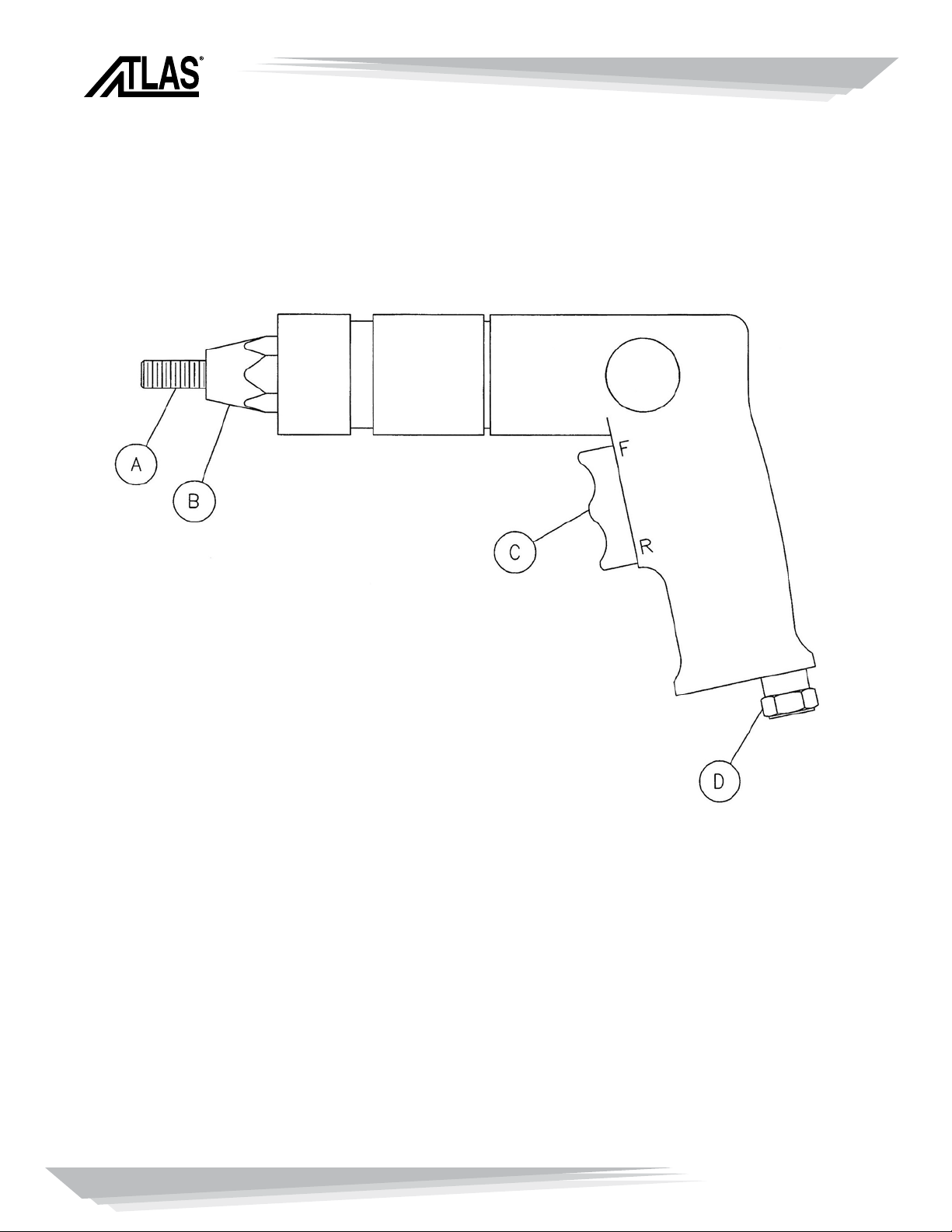
MAIN COMPONENTS
(Figure 1)
MAIN COMPONENTS
A. Socket head cap screw (pull-up stud)
B. Anvil
C. Trigger
Position ‘F’ Forward Rotation
PennEngineering • www.pemnet.com
2
Position ‘R’ Reverse Rotation
D. Air line connector
© Copyright 2009
Page 3

GENERAL NOTES AND TECHNICAL DATA
GENERAL NOTES:
The model 801, 802, 803, 804 and 806 pneumatic tools are designed to provide a user
friendly, light weight, quiet, fast and powerful threaded insert installation tool. They are
designed to provide long life and trouble free service.
Filter regulator oil Schrader Bellows® Model No. F442 is recommended for use with
these air tools. The performance of these components is reliable and they provide
clean, oiled and regulated air to the tools.
Recommended hose size is 5/16” or 3/8” inside the diameter.
If a quick disconnect assembly is used utilize components with an inside diameter of ¼
inch, so that the air supply is not restricted.
It is recommended that the filter regulator oiler be located within sixty inches, or less,
from the air tool so that air pressure readings at the gage are indicative of what the
tool is actually receiving.
We recommend that you use a good grade of socket head cap screw with good clean
threads.
TECHNICAL DATA:
Recommended air pressure: 45 to 100 psi
Weight (801, 802, 803, 804): 2.5 lbs.
Weight (806): 3 lbs.
The air supply to the tools should be dry and free of contamination, to prevent
premature wear and tear of the internal components. IT is essential for reliable
installation of fasteners, that a filter, pressure regulator, and oiler system be used, and
located in close proximity to the tool.
PennEngineering • www.pemnet.com
3
Page 4
GENERAL OPERATING INSTRUCTIONS
OPERATING INSTRUCTIONS:
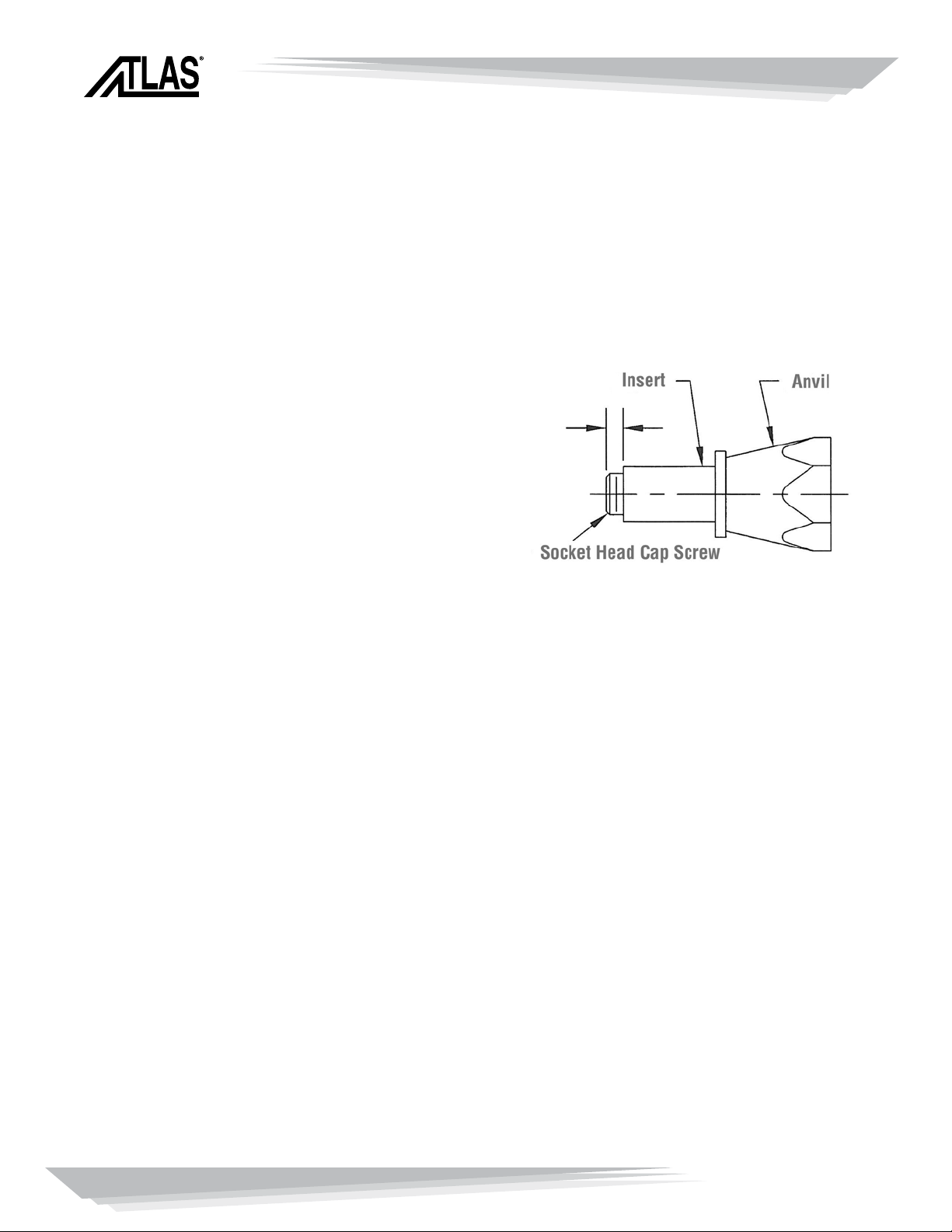
With the tool disconnected from the airline, check to see that the socket head cap
screw extends beyond the face of the anvil far enough to allow at least one thread
of the screw to extend beyond the end of the insert. If the screw is not long enough,
measure what is required and get a socket
head cap screw that is long enough.
If you set up on a first grip fastener and you
are going to install second grip inserts in
the same work area, get a screw that is long
enough to extend at least one thread beyond
the end of the longest fastener.
Now, connect the air line to the tool. Hold the threaded insert to the tool mandrel.
Actuate position ‘F’ of the trigger (figure 1) and start engagement of the insert threads
on to the tool mandrel. Stop fastener engagement just before the head of the insert
comes in contact with anvil face.
Insert the fastener into the installation hole of a test plate, that is the same material
and thickness, as the actual application.
Actuate the position ‘F’ of the trigger and let the socket head cap screw mandrel drive
through the fastener and clinch it securely into the test plate and allow the air tool to
stall.
Actuate position ‘R’ of the trigger (the bottom rocker) and disengage the tool mandrel
from the installed fastener.
PennEngineering • www.pemnet.com
4
Page 5
OPERATING INSTRUCTIONS FOR MODEL 806
OPERATING INSTRUCTIONS FOR MODEL 806:
600 RPM Pneumatic spin/spin tool with internal clutch, capable of installing thread
sizes of M4-M6, 632-1/4.
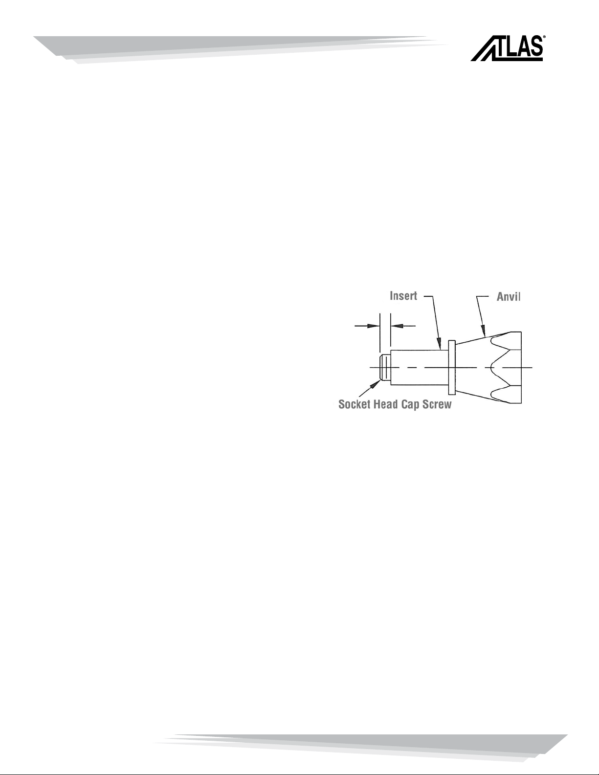
With the tool disconnected from the airline, check to see that the socket head cap
screw extends beyond the face of the anvil far enough to allow at least one thread
of the screw to extend beyond the end of the insert. If the screw is not long enough,
measure what is required and get a socket
head cap screw that is long enough.
If you set up on a first grip fastener and you
are going to install second grip inserts in
the same work area, get a screw that is long
enough to extend at least one thread beyond
the end of the longest fastener.
Now, connect the air line to the tool. Hold the threaded insert to the tool mandrel.
Actuate position ‘F’ of the trigger (figure 1) and start engagement of the insert threads
on to the tool mandrel. Stop fastener engagement just before the head of the insert
comes in contact with anvil face. Rotate torque adjusting cap (Part #806-39) to desired
thread size (M4-M6, 632-1/4).
Insert the fastener into the installation hole of a test plate, that is the same material
and thickness, as the actual application.
Actuate the position ‘F’ of the trigger and let the socket head cap screw mandrel drive
through the fastener and clinch it securely into the test plate and allow the air tool to
stall.
Actuate position ‘R’ of the trigger (the bottom rocker) and disengage the tool mandrel
from the installed fastener.
PennEngineering • www.pemnet.com
5
Page 6

PREVENTIVE MAINTENANCE
PREVENTIVE MAINTENANCE:
Lubricate Socket Head Cap Screw:
It is recommended that you dip the first few threads in light oil every several
installations to reduce wear.
Lubrication of Gearing:
All air tools containing gears should be lubricated weekly with standard gear grease.
(Caution: excessive lubricant will affect the tools speed and power.)
Flushing of Tool:
It is recommended that air tools be flushed weekly with a solution of three parts
cleaning solvent and one part oil.
Proper Handling:
Although very durable, pneumatic tools have sensitive internal components and need
to be treated as such. Droppings or dragging these tools, could cause damage to inner
mechanism.
If at any time, you have any difficult with the operation or maintenance of this tool, feel
free to call collect.
Atlas Customer Service: (215) 766-5987
Toll Free: 877-682-2505
E-mail: atlas@pemnet.com
PennEngineering • www.pemnet.com
6
Page 7

ATLAS 800 SERIES TROUBLE SHOOTING GUIDE
1. Do I need to put my tool on a regulated supply line?
Yes, because it reduces any complications with high pressures and overloads on the tool or the part. Also the
supply line should have a filter on it to remove any dirt or any other contaminate from the air supplied.
2. Why does my installation tool strip the threads out of my part?
The power of the tool is too high and needs to be reduced. Air pressure needs to be reduced to reduce the power of
the tool.
3. Why do I keep breaking and bending the installation studs?
The power of the tool is too high and needs to be reduced. Air pressure needs to be reduced to reduce the power of
the tool.
4. How much air pressure does it take to properly install my part?
A sample instillation needs to be done at various pressure settings to determine a good pressure without damaging
the tool or part but fully installs the part. Recommendations are to start with lower pressure.
5. I can’t fine tune the line pressure of the supply line to the tool. What do I do?
You must adjust the pressure of the supply line while the tool is running. NO part should be on the tool while doing
this.
6. Will my smaller tool or larger tool install a larger or smaller part?
It is not recommended to use the tools for larger or smaller parts than what is recommended, But if very cautious,
with pressures you may use a larger tool with a smaller part. You cannot use a smaller tool for a larger part
because it can severely damage internal workings of the tool.
7. How often should I do PM on my tool?
Twice in a normal operating day (8 hour usage), you should disconnect the air line and give a small bit of oil into the
air inlet of the gun. Once a week you should remove the nose piece from the gun and remove the bearing and cap
screw for cleaning and grease.
8. How often should I replace the cap screw or bearing?
Any time you see or feel excessive wear on any of the parts, you should clean or replace them immediately.
9. Can I repair my own tool?
It is not recommended, but you can only if the tool is older than 1 year and the warranty has expired, otherwise you
will void the warranty. Also be careful not to damage housing when disassembling.
10. Where do I find the parts list for my gun?
Most of the time there will be a repair manual for your tool in the container that the original shipment came in.
There is a parts list and breakdown in this book. If you do not have a repair manual, ask and we can fax you one or
even mail or e-mail one. There is a full manual in PDF format available.
11. How do I send my tool in for repairs?
You should call your supplier to let them know that you have a tool or part that needs to be returned to Atlas™ for
repairs. Then you or the supplier can call us for a Repair Order number for tracking the tool as it comes in for repair.
PennEngineering • www.pemnet.com
7
Page 8
MODEL 801 / 802
NOSE PIECE CONFIGURATIONS
SEE CHART
PennEngineering • www.pemnet.com
8
SPECIFICATIONS
FREE SPEED: 3000 (RPM)
801 ONLY
FREE SPEED: 1500 (RPM)
802 ONLY
AIR PRESSURE: 90 PSI
AIR INLET: 1/4” (NPT)
AIR CONSUMPTION: 5CFM
THREAD SIZE: M3, M4
HOSE SIZE: 3/8” (9.5 MM)
801: 4-40, 6-32, 8-32
3MM, 4MM
802: #1024, 1032, 5MM
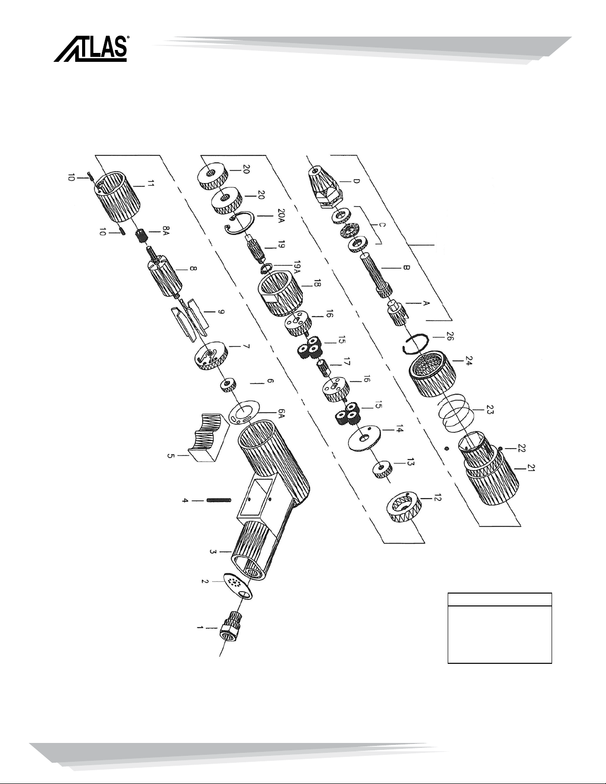
Page 9

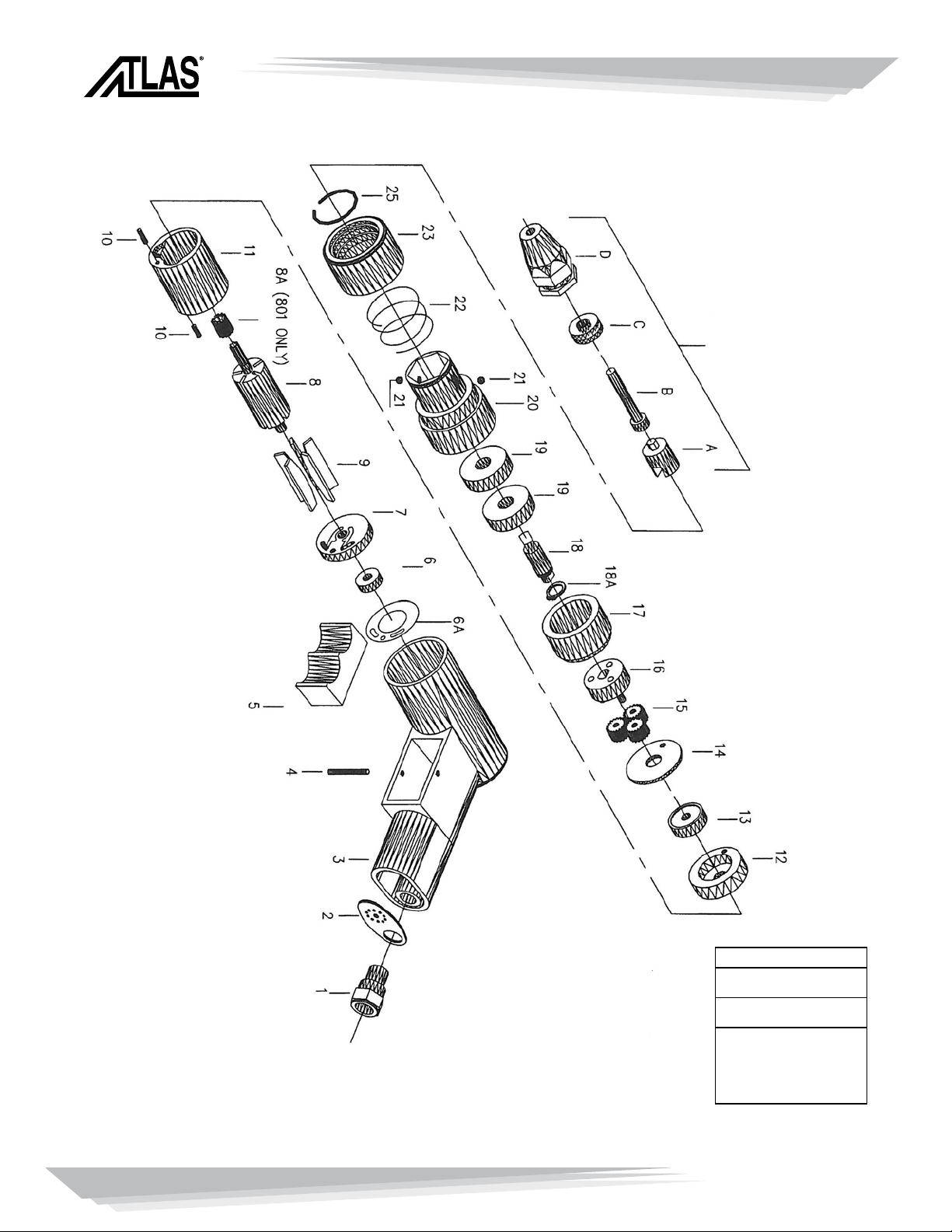
MODEL 801 / 802
EXPLODE NO. DESCRIPTION ATLAS P/N QTY.
1 Air Inlet SPN-00001 1
2 Exhaust diffuser SPN-00002 1
3 Handle Assembly SPN-00003 1
4 Roll Pin ø3 X 28 (MM) SPN-00004 1
5 Trigger SPN-00005 1
6A Gasket SPN-00040 1
6 Ball Bearing (696z) SPN-0006 1
7 Rear End Plate SPN-0007 1
8 Rotor 67 SPN-0008 1
8A Sun Gear (12T) SPN-00029 1
9 Rotor Blade SPN-0009 5
10 Roll Pin ø 2.5 X 10 (MM) SPN-00010 2
11 Cylinder SPN-00011 1
12 Front End Plate ø 34 X 6 (MM) SPN-00013 1
13 Ball Bearing (626z) SPN-00015 1
14 Washer SPN-00016 1
15 Planet Gear (15T) – (801 only) SPN-00017 3
15 Planet Gear (18T) – (802 only) SPN-00026 3
16 Planet Pin (801 only) SPN-00027 1
16 Planet Pin (802 only) SPN-00018 1
17 Internal Gear SPN-00044 1
18 Drive Spindle SPN-00020 1
18A Retaining Ring SPN-00019 1
19 Ball Bearing (6200z) SPN-00046 2
20 Nose Housing SPN-00021 1
21 Locking Balls SPN-00022 2
22 Change Value Spring SPN-00023 1
23 Quick Change Sleeve SPN-00024 1
25 Circlip SPN-00025 1
A Hex Driver See Chart Below 1
B Screw Mandrel See Chart Below 1
C Bearings Assy. See Chart Below 1
D Anvil See Chart Below 1
Complete
Thread Size Nose Piece A B C D
Assembly
4-40 AENP-440 AEHD-4 AESH-440-150 AEPB-4 ANSS-4
6-32 AENP-632 AEHD-6 AESH-632-150 AEPB-6 ANSS-6
8-32 AENP-832 AEHD-8 AESH-832-150 AEPB-8 ANSS-8
10-24 AENP-1024 AEHD-10 AESH-1024-150 AEPB-10 ANSS-10
10-32 AENP-1032 AEHD-10 AESH-1032-150 AEPB-10 ANSS-10
M3 AENP-M3 AEHD-M3 AESH-M3-35 AEPB-M3 ANSS-M3
M4 AENP-M4 AEHD-M4 AESH-M4-35 AEPB-M4 ANSS-M4
M5 AENP-M5 AEHD-M5 AESH-M5-45 AEPB-M5 ANSS-M5
PennEngineering • www.pemnet.com
9
Page 10
MODEL 803 / 804
NOSE PIECE CONFIGURATIONS
SEE CHART
PennEngineering • www.pemnet.com
10
SPECIFICATIONS
FREE SPEED: 600/400 (RPM)
AIR PRESSURE: 90-110 PSI
AIR INLET: 1/4” (NPT)
AIR CONSUMPTION: 5 CFM
THREAD SIZE: M8, M10
HOSE SIZE: 3/8” (9.5 MM)
803: 2520, 2528, 6MM
804: 3118, 3124, 3716, 3718
8MM, 10MM
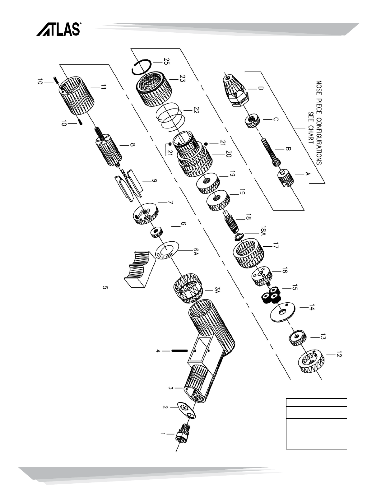
Page 11

MODEL 803 / 804
EXPLODE NO. DESCRIPTION ATLAS P/N QTY.
1 Air Inlet SPN-00001 1
2 Exhaust diffuser SPN-00002 1
3 Handle Assembly SPN-00003 1
4 Roll Pin ø3 X 28 (MM) SPN-00004 1
5 Trigger SPN-00005 1
6A Gasket SPN-00040 1
6 Ball Bearing (696z) SPN-00006 1
7 Rear Plate SPN-00007 1
8A Sun Gear (#803 only) SPN-00029 1
8 Rotor 6t (#803 only) SPN-00008 1
9 Rotor Blade SPN-0009 5
10 Roll Pin ø 2.5 X 10 (MM) SPN-00010 2
11 Cylinder SPN-00011 1
12 Front End Plate ø 34x6 (MM) SPN-00013 1
12 Front End Plate ø 34x8 (MM) SPN-00054 1
13 Ball Bearing 626zz (#803) SPN-00015 1
13 Ball Bearing 698zz (#804) SPN-00028 1
14 Washer SPN-00016 1
15 Planet Gear (15t) (#803) SPN-00017 6
15 Planet Gear (16t) (#804) SPN-00036 6
16 Gear Cage (#803) SPN-00027 2
16 Gear Cage (#804) SPN-00037 2
17 Sun Gear (12t) (#803) SPN-00041 1
17 Sun Gear (9t) (#804) SPN-00038 1
18 Internal Gear (#803) SPN-00045 1
18 Internal Gear (#804) SPN-00049 1
19 Drive Spindle SPN-00020 1
19A Retaining Ring SPN-00019 1
20 Bearing (6200z) SPN-00046 2
21 Nose Housing SPN-00032 1
22 Locking Balls SPN-00022 2
23 Spring SPN-00023 1
24 Quick Change Sleeve (#803) SPN-00024 1
24 Quick Change Sleeve (#804) SPN-00024 1
26 Circlip SPN-00025 1
A Hex Driver See Chart Below 1
B Screw Mandrel See Chart Below 1
C Bearing Set See Chart Below 1
D Anvil See Chart Below 1
Complete
Thread Size Nose Piece A B C D
Assembly
1/4 -20 AENP-2520 AEHD-25 AESH-2520-175 AEPB-25 ANSS-25
1/4-28 AENP-2528 AEHD-25 AESH-2528-175 AEPB-25 ANSS-25
5/16-18 AENP-3118 AEHD-31 AESH-3118-175 AEPB-31 ANSS-31
5/16-24 AENP-3124 AEHD-31 AESH-3124-175 AEPB-31 ANSS-31
3/8-16 AENP-3716 AEHD-37 AESH-3716-175 AEPB-37 ANSS-37
3/8-24 AENP-3724 AEHD-37 AESH-3724-175 AEPB-37 ANSS-37
M6 AENP-M6 AEHD-M6 AESH-M6-45 AEPB-M6 ANSS-M6
M8 AENP-M8 AEHD-M8 AESH-M8-45 AEPB-M8 ANSS-M8
M10 AENP-M10 AEHD-M10 AESS-M10-45 AEPB-M10 ANSS-M10
PennEngineering • www.pemnet.com
11
Page 12
MODEL 805
PennEngineering • www.pemnet.com
12
SPECIFICATIONS
FREE SPEED: 900 (RPM)
805 ONLY
AIR PRESSURE: 90 PSI
AIR INLET: 1/4” (NPT)
AIR CONSUMPTION: 5CFM
THREAD SIZE: M3, M4
HOSE SIZE: 3/8” (9.5 MM)
805: 1/4-20, 1/4-28, M6
Page 13

MODEL 805
EXPLODE NO. DESCRIPTION ATLAS P/N QTY.
1 Air Inlet SPN-00001 1
2 Exhaust Diffuser SPN-00002 1
3 Handle Assembly SPN-00003 1
3A Handle Extension SPN-00034 1
4 Roll Pin ø3 X 28 (MM) SPN-00004 1
5 Trigger SPN-00005 1
6 Ball Bearing (696z) SPN-00006 1
6A Gasket SPN-00040 1
7 Rear End Plate SPN-00007 1
8 Rotor 6T SPN-00052 1
9 Rotor Blade SPN-00053 5
10 Roll Pin ø2.5 X 10 (MM) SPN-00010 2
11 Cylinder SPN-00055 1
12 Front End Plate ø34x6 (MM) SPN-00013 1
13 Ball Bearing (626z) SPN-00015 1
14 Washer SPN-00016 1
15 Planet Gear (18T) SPN-00026 3
16 Planet Pin SPN-00018 1
17 Internal Gear SPN-00044 1
18 Drive Spindle SPN-00020 1
18A Retaining Ring SPN-00019 1
19 Ball Bearing (6200z) SPN-00046 2
20 Nose Housing SPN-00021 1
21 Locking Balls SPN-00022 2
22 Change Value Spring SPN-00023 1
23 Quick Change Sleeve SPN-00024 1
25 Circlip SPN-00025 1
A Hex Driver See Chart Below 1
B Screw Mandrel See Chart Below 1
C Bearings Assy. See Chart Below 1
D Anvil See Chart Below 1
Complete
Thread Size Nose Piece A B C D
Assembly
1/4 -20 AENP-2520 AEHD-25 AESH-2520-175 AEPB-25 ANSS-25
1/4-28 AENP-2528 AEHD-25 AESH-2528-175 AEPB-25 ANSS-25
M6 AENP-M6 AEHD-M6 AESH-M6-45 AEPB-M6 ANSS-M6
PennEngineering • www.pemnet.com
13
Page 14
MODEL 806
SPECIFICATIONS
FREE SPEED: 600 (RPM)
AIR PRESSURE: 90 PSI
AIR INLET: 1/4” (NPT)
AIR CONSUMPTION: 5CFM
THREAD SIZE: #4-40 - 3/8”
HOSE SIZE: 3/8” (9.5 MM)
PennEngineering • www.pemnet.com
14
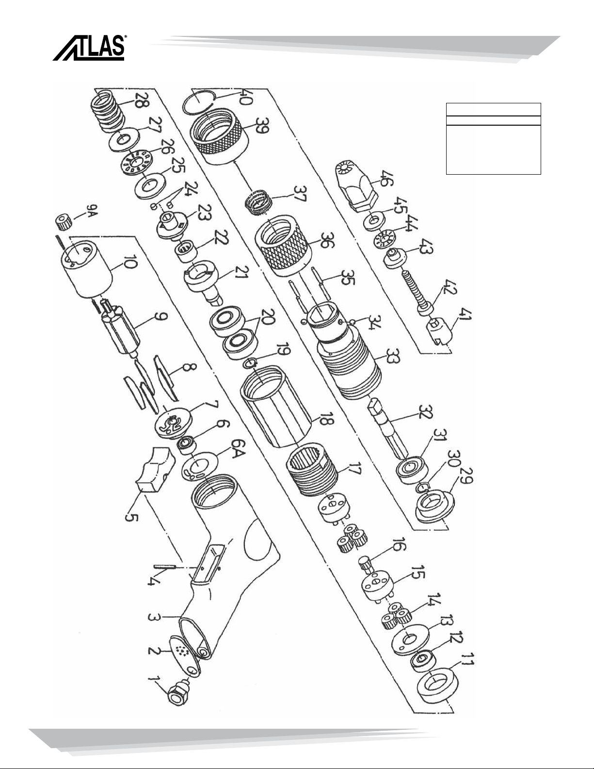
Page 15

MODEL 806
PART NO. DESCRIPTION QTY.
806-1 Air Inlet 1
806-2 Exhaust Diffuser 1
806-3 Handle Assembly 1
806-4 Pin 1
806-5 Trigger 1
806-6A Gasket 1
806-6 Ball Bearing (696) 1
806-7 Rear Plate (SPN-00007) 1
806-8 Rotor Blade (SPN-00009) 5
806-9 Rotor 1
806-9A Planet Gear 1
806-10 Cylinder 1
806-11 Front End Plate (SPN-00054) 1
806-12 Ball Bearing (626) 1
806-13 Washer 1
806-14 Planet Gear (15T) 6
806-15 Planet Pin 2
806-16 Gear 1
806-17 Planet Cage (Long) 1
806-18 Connecting Tube (Long) 1
806-19 Retaining Ring 1
806-20 Ball Bearing 2
806-21 Clutch 1
806-22 Ball Bearing 1
806-23 Steel Ball Fixing Plate 1
806-24 Cam Rider Ball 2
806-25 Washer 1
806-26 Ball Bearing 1
806-27 Washer 1
806-28 Change Value Spring 1
806-29 Drive Housing 1
806-30 Retaining Ring 1
806-31 Ball Bearing 1
806-32 Internal Gear 1
806-33 Nose Housing 1
806-34 Cam Rider Ball 2
806-35 Pin 4
806-36 Torque Adjusting Cap 1
806-37 Change Value Spring 1
806-39 Pin Stopper Washer 1
806-40 Spring Receiver 1
806-41 Spindle (Back) 1
806-42 Screw 1
806-43 Spindle Lock Screw 1
806-44 Ball Bearing 1
806-45 Washer 1
806-46 Spindle Cover 1
PennEngineering • www.pemnet.com
15
Page 16

SEE CHART
MODEL 808
NOSE PIECE CONFIGURATIONS
PennEngineering • www.pemnet.com
16
SPECIFICATIONS
FREE SPEED: 275 (RPM)
AIR PRESSURE: 90 PSI
AIR INLET: 1/4” (NPT)
AIR CONSUMPTION: 5 CFM
THREAD SIZE: 1/2”, M12
HOSE SIZE: 3/8” (9.5 MM)
Page 17

MODEL 808
EXPLODE NO. DESCRIPTION ATLAS P/N QTY.
1 Air Inlet SPN-00001 1
2 Exhaust diffuser SPN-00002 1
3 Handle Assembly SPN-00003 1
3A Handle Extension SPN-00034 1
4 Roll Pin ø3 X 28 (MM) SPN-00004 1
5 Trigger SPN-00005 1
6 Ball Bearing (696z) SPN-00006 1
6A Gasket SPN-00040 1
7 Rear End Plate SPN-00007 1
8 Rotor 6t (Long) SPN-00052 1
9 Rotor Blade SPN-00053 5
10 Roll Pin ø 2.5 X 10 (MM) SPN-00010 2
11 Cylinder SPN-00055 1
12 Front End Plate ø 34x6 (MM) SPN-00013 1
13 Ball Bearing 626zz SPN-00015 1
14 Washer SPN-00016 1
15A Planet Gear 18t SPN-00026 3
15B Planet Gear 16t SPN-00036 3
16A Gear Cage SPN-00018 1
16B Gear Cage SPN-00037 1
17 Sun Gear (9t) SPN-00038 1
18A Internal Gear (#1) SPN-00056 1
18B Internal Gear (#2) SPN-00057 1
19 Drive Spindle SPN-00020 1
19A Retaining Ring SPN-00019 1
20 Bearing 6200z SPN-00046 2
20A Retaining Clip SPN-00047 1
21 Nose Housing SPN-00032 1
22 Locking Balls SPN-00022 2
23 Change Value Spring SPN-00023 1
24 Quick Change Sleeve SPN-00024 1
25 Circlip SPN-00025 1
26 Spindle Cover SPN-00050 1
A Hex Driver See Chart Below 1
B Screw Mandrel See Chart Below 1
C Bearing Set See Chart Below 1
D Anvil See Chart Below 1
Complete
Thread Size Nose Piece A B C D
Assembly
1/2-13 AENP-5013 AEHD-50 AESH-5013-225 AEPB-50 ANSS-50
1/2-20 AENP-5020 AEHD-50 AESH-5020-225 AEPB-50 ANSS-50
7/16-20 AENP-4320 AEHD-43 AESH-4320-225 AEPB-43 ANSS-43
M12 AENP-M12 AEHD-M12 AESH-M12-45 AEPB-M12 ANSS-M12
PennEngineering • www.pemnet.com
17
Page 18

MODEL 901
SEE NOSE ASSEMBLY CHART
PennEngineering • www.pemnet.com
18
SPECIFICATIONS
FREE SPEED: 3000 (RPM)
AIR PRESSURE: 90-110 PSI
AIR INLET: 1/4” (NPT)
AIR CONSUMPTION: 5 CFM
THREAD SIZE: #4/3MM thru #8/4MM
HOSE SIZE: 3/8” (9.5 MM)
Page 19

MODEL 901
EXPLODE NO. DESCRIPTION ATLAS P/N QTY.
1 Motor Housing SPN-00150 1
2 Inlet Bushing SPN-00001 1
3 Stop Ring SPN-00151 1
4 Deflector SPN-00152 1
5 Housing Cap SPN-00153 1
6 Screw SPN-00154 2
7 Screw Pin SPN-00155 1
8 Lever SPN-00156 1
9 Gasket SPN-00157 1
10 Valve Screw SPN-00158 1
11 “O”-Ring SPN-00159 1
12 Reverse Retainer SPN-00160 1
13 Valve Spring SPN-00161 1
14 Throttle Valve SPN-00162 1
15 “O”-Ring SPN-00163 1
16 Valve Bushing SPN-00164 1
17 Reverse Valve SPN-00165 1
18 Reverse Valve Bushing SPN-00166 1
19 Reverse Valve Bushing SPN-00167 1
20A Lock Ring SPN-00168 1
20 Gasket SPN-00040 1
21 Ball Bearing (696 ZZ) SPN-00006 1
22 Rear End Plate SPN-00007 1
23 Cylinder SPN-00011 1
23A Roll Pin (ø2.55mmX ø10mm) SPN-00010 2
24 Rotor Blades SPN-00009 5
25 Rotor (6t) SPN-00008 1
26 Sun Gear SPN-00029 1
27 Front End Plate SPN-00013 1
27A Ball Bearing (626 ZZ) SPN-00015 1
28 Washer SPN-00016 1
29 Planet Gear (15t) SPN-00017 3
30 Gear Cage (.700) SPN-00027 1
32 Internal Gear SPN-00044 1
33A Retainer Ring SPN-00019 1
33 Driver Spindle SPN-00020 1
34 Ball Bearing (6200 Z) SPN-00046 2
34A Retaining Ring SPN-00047 1
35 Nose Housing SPN-00021 1
36 Locking Balls SPN-00022 2
37 Spring SPN-00023 1
38 Quick Change Sleeve SPN-00024 1
39 Circlip SPN-00025 1
40 Draw Bolt Driver
41 Screw
42 Rear Thrust Plate
43 Roller Bearing
44 Washer
45 Nose Piece
See Charts On Pages 25, 26 & 27 1
See Charts On Pages 25, 26 & 27 1
See Charts On Pages 25, 26 & 27 1
See Charts On Pages 25, 26 & 27 1
See Charts On Pages 25, 26 & 27 1
See Charts On Pages 25, 26 & 27 1
PennEngineering • www.pemnet.com
19
Page 20

MODEL 902
SEE NOSE ASSEMBLY CHART
PennEngineering • www.pemnet.com
20
SPECIFICATIONS
FREE SPEED: 1500 (RPM)
AIR PRESSURE: 90-110 PSI
AIR INLET: 1/4” (NPT)
AIR CONSUMPTION: 5 CFM
THREAD SIZE: #10/5MM thru 1/4” /6MM
HOSE SIZE: 3/8” (9.5 MM)
Page 21

MODEL 902
NO. PART NO. DESCRIPTION PART NO. QTY.
1 Motor Housing SPN-00150 1
2 Inlet Bushing SPN-00001 1
3 Stop Ring SPN-00151 1
4 Deflector SPN-00152 1
5 Housing Cap SPN-00153 1
6 Screw SPN-00154 2
7 Screw Pin SPN-00155 1
8 Lever SPN-00156 1
9 Gasket SPN-00157 1
10 Valve Screw SPN-00158 1
11 “O”-Ring SPN-00159 1
12 Reverse Retainer SPN-00160 1
13 Valve Spring SPN-00161 1
14 Throttle Valve SPN-00162 1
15 “O”-Ring SPN-00163 1
16 Valve Bushing SPN-00164 1
17 Reverse Valve SPN-00165 1
18 Reverse Valve Bushing SPN-00166 1
19 Reverse Valve Bushing SPN-00167 1
20A Lock Ring SPN-00168 1
20 Gasket SPN-00040 1
21 Ball Bearing (696 ZZ) SPN-00006 1
22 Rear End Plate SPN-00007 1
23 Cylinder SPN-00011 1
23A Roll Pin (ø2.55mmX ø10mm) SPN-00010 2
24 Rotor Blades SPN-00009 5
25 Rotor (6t) SPN-00008 1
27 Front End Plate SPN-00013 1
27A Ball Bearing (626 ZZ) SPN-00015 1
28 Washer SPN-00016 1
29 Planet Gear (18t) SPN-00017 3
30 Gear Cage (.638) SPN-00027 1
32 Internal Gear SPN-00044 1
33A Retainer Ring SPN-00019 1
33 Driver Spindle SPN-00020 1
34 Ball Bearing (6200 Z) SPN-00046 2
34A Retaining Ring SPN-00047 1
35 Nose Housing SPN-00021 1
36 Locking Balls SPN-00022 2
37 Spring SPN-00023 1
38 Quick Change Sleeve SPN-00024 1
39 Circlip SPN-00025 1
40 Draw Bolt Driver
41 Screw
42 Rear Thrust Plate
43 Roller Bearing
44 Washer
45 Nose Piece
See Charts On Pages 25, 26 & 27 1
See Charts On Pages 25, 26 & 27 1
See Charts On Pages 25, 26 & 27 1
See Charts On Pages 25, 26 & 27 1
See Charts On Pages 25, 26 & 27 1
See Charts On Pages 25, 26 & 27 1
PennEngineering • www.pemnet.com
21
Page 22

MODEL 903
SEE NOSE ASSEMBLY CHART
PennEngineering • www.pemnet.com
22
SPECIFICATIONS
FREE SPEED: 600 (RPM)
AIR PRESSURE: 90-110 PSI
AIR INLET: 1/4” (NPT)
AIR CONSUMPTION: 5 CFM
THREAD SIZE: 5/16” / 8MM
HOSE SIZE: 3/8” (9.5 MM)
Page 23

MODEL 903
EXPLODE NO. DESCRIPTION PART NO. QTY.
1 Motor Housing SPN-00150 1
2 Inlet Bushing SPN-00001 1
3 Stop Ring SPN-00151 1
4 Deflector SPN-00152 1
5 Housing Cap SPN-00153 1
6 Screw SPN-00154 2
7 Screw Pin SPN-00155 1
8 Lever SPN-00156 1
9 Gasket SPN-00157 1
10 Valve Screw SPN-00158 1
11 “O”-Ring SPN-00159 1
12 Reverse Retainer SPN-00160 1
13 Valve Spring SPN-00161 1
14 Throttle Valve SPN-00162 1
15 “O”-Ring SPN-00163 1
16 Valve Bushing SPN-00164 1
17 Reverse Valve SPN-00165 1
18 Reverse Valve Bushing SPN-00166 1
19 Reverse Valve Bushing SPN-00167 1
20A Lock Ring SPN-00168 1
20 Gasket SPN-00040 1
21 Ball Bearing (696 ZZ) SPN-00006 1
22 Rear End Plate SPN-00007 1
23 Cylinder SPN-00011 1
23A Roll Pin (ø2.55mmX ø10mm) SPN-00010 2
24 Rotor Blades SPN-00009 5
25 Rotor (6t) SPN-00008 1
26 Sun Gear SPN-00029 1
27 Front End Plate SPN-00013 1
27A Ball Bearing (626 ZZ) SPN-00015 1
28 Washer SPN-00016 1
29 Planet Gear (15t) SPN-00017 6
30 Gear Cage SPN-00027 2
31 Sun Gear (12t) SPN-00041 1
32 Internal Gear SPN-00045 1
33A Retainer Ring SPN-00019 1
33 Driver Spindle SPN-00020 1
34A Retaining Ring SPN-00047 1
34 Ball Bearing (6200 Z) SPN-00046 2
35 Nose Housing SPN-00021 1
36 Locking Balls SPN-00022 2
37 Spring SPN-00023 1
38 Quick Change Sleeve SPN-00024 1
39 Circlip SPN-00025 1
40 Draw Bolt Driver
41 Screw
42 Rear Thrust Plate
43 Roller Bearing
44 Washer
45 Nose Piece
See Charts On Pages 25, 26 & 27 1
See Charts On Pages 25, 26 & 27 1
See Charts On Pages 25, 26 & 27 1
See Charts On Pages 25, 26 & 27 1
See Charts On Pages 25, 26 & 27 1
See Charts On Pages 25, 26 & 27 1
PennEngineering • www.pemnet.com
23
Page 24

MODELS 911, 912 & 913
PART NO. DESCRIPTION QTY. PART NO. DESCRIPTION QTY.
913-1 MOTOR HOUSING 1 912-33 GEAR CAGE 1
913-2 AIR INLET 1 913-33 GEAR CAGE 2
913-3 RETAINER RING 1 913-34 SUN GEAR (12T) 1
913-4 DEFLECTOR 1 911-35 INTERNAL GEAR 1
913-5A SILENCER 2 912-35 INTERNAL GEAR 1
913-7 LEVER PIN 1 913-35 INTERNAL GEAR 1
913-8 LEVER 1 913-36 RETAINING RING 1
913-9A EXHAUST COVER 1 913-37 GEAR SPINDLE 1
913-10 VALVE SCREW 1 913-38 BALL BEARING (6000) 1
913-11 O-RING 1 913-39 BALL BEARING (6001) 1
913-12 REVERSE RETAINER 1 913-40 PINION 1
913-13 VALVE SPRING 1 912-41 LOCK RING 1
913-14 THROTTLE VALVE 1 913-41 LOCK RING 1
913-15 O-RING 1 913-42 BALL CAP 1
913-16 VALVE BRUSHING 1 913-43 ANGLE HOUSING 1
913-17R REVERSE VALVE (W TYPE) 1 913-44 SET CAP 1
913-17F REVERSE VALVE 9S TYPE) 1 913-45 RETAINER RING 1
913-18 REVERSE VALVE BUSHING 1 913-46 BALL BEARING (698ZZ) 1
913-19 REVERSE VALVE SPRING 1 913-47 GEAR 1
913-21 GASKET 1 913-48 BALL BEARING (6000zZ) 1
913-22 BALL BEARING 9696ZZ 1 913-49 KEY 1
913-23 REAR END PLATE 1 913-50 SPINDLE 1
913-24 ROTOR BLADE 5 913-51 NOSE HOUSING 1
913-25 ROTOR (6T) 1 913-52 LOCKING BALLS 1
913-26 PLANET GEAR (12 T) 1 913-53 CHANGE VALUE SPRING 2
913-27 ROLL PIN (Ø2.5*Ø10) 2 913-54 QUICK CHANGE SLEEVE 1
913-28 CYLINDER 1 913-55 C CLIP 1
913-29 FRONT END PLATE (Ø34*Ø6) 1 913-56 DRAW BOLT DRIVER 1
913-30 BALL BEARING (626ZZ) 1 913-57 SCREW 1
913-31 WASHER 1 913-58 REAR THRUST PLATE 1
911-32 PLANET GEAR (15T) 3 913-59 ROLLER BEARINGS 1
912-32 PLANET GEAR (18T) 3 913-60 WASHER 1
913-32 PLANET GEAR (15T) 6 913-61 NOSE PIECE 1
911-33 GEAR CAGE 1
PennEngineering • www.pemnet.com
24
Page 25

NOSE ASSEMBLY
NOSE
( D )
DRIVER
( A )
SOCKET HEAD CAB SCREW
( B )
WASHER
BEARING
WASHER
( C )
BEARING SET
PNEUMATIC INSTALLATION
TOOL NOSE ASSEMBLY
#4-3MM THROUGH 3/8-10MM
Complete
Thread Size Nose Piece A B C D
Assembly
4-40 AENP-440 AEHD-4 AESH-440-150 AEPB-4 ANSS-4
6-32 AENP-632 AEHD-6 AESH-632-150 AEPB-6 ANSS-6
8-32 AENP-832 AEHD-8 AESH-832-150 AEPB-8 ANSS-8
M3 AENP-M3 AEHD-M3 AESH-M3-150 AEPB-M3 ANSS-M3
M4 AENP-M4 AEHD-M4 AESH-M4-150 AEPB-M4 ANSS-M4
1/4-20 AENP-2520 AEHD-25 AESH-2520-175 AEPB-25 ANSS-25
1/4-28 AENP-2528 AEHD-25 AESH-2528-175 AEPB-25 ANSS-25
5/16-18 AENP-3118 AEHD-31 AESH-3118-175 AEPB-31 ANSS-31
5/16-24 AENP-3124 AEHD-31 AESH-3124-175 AEPB-31 ANSS-31
M8 AENP-M8 AEHD-M8 AESH-M8-175 AEPB-M8 ANSS-M8
3/8-16 AENP-3716 AEHD-37 AESH-3716-175 AEPB-37 ANSS-37
3/8-24 AENP-3724 AEHD-37 AESH-3724-175 AEPB-37 ANSS-37
M10 AENP-M10 AEHD-M10 AESH-M10-175 AEPB-M10 ANSS-M10
PennEngineering • www.pemnet.com
25
Page 26

NOSE PIECE CONFIGURATIONS
SEE CHART
B
NOSE ASSEMBLY
SPN-00050
A
C
D
PNEUMATIC INSTALLATION
TOOL NOSE ASSEMBLY
½, 12MM
Complete
Thread Size Nose Piece A B C D
Assembly
1/2-13 AENP-5013 AEHD-50 AESH-5013-225 AEPB-50 ANSS-50
1/2-20 AENP-5020 AEHD-50 AESH-5020-225 AEPB-50 ANSS-50
M12 AENP-M12 AEHD-M12 AESH-M12-175 AEPB-M12 ANSS-M12
PennEngineering • www.pemnet.com
26
Page 27

STUD SERIES NOSE ASSEMBLY
ASSEMBLY
BEARING SET
ANVIL
( C )
DRIVER
( A )
( B )
Assembly A B C
AESNP-632 AESD-632 AEPB-31 AESA-6
AESNP-832 AESD-832 AEPB-31 AESA-8
AESNP-1024 AESD-1024 AEPB-37 AESA-10
AESNP-1032 AESD-1032 AEPB-37 AESA-10
AESNP-2520 AESD-2520 AEPB-37 AESA-25
AESNP-3118 AESD-3118 AEPB-100 AESA-37
AESNP-3716 AESD-3716 AEPB-100 AESA-37
AESNP-M4 AESD-M4 AEPB-31 AESA-8
AESNP-M5 AESD-M5 AEPB-37 AESA-10
AESNP-M6 AESD-M6 AEPB-37 AESA-25
AESNP-M8 AESD-M8 AEPB-100 AESA-37
AESNP-M10 AESD-M10 AEPB-100 AESA-37
PennEngineering • www.pemnet.com
27
Page 28
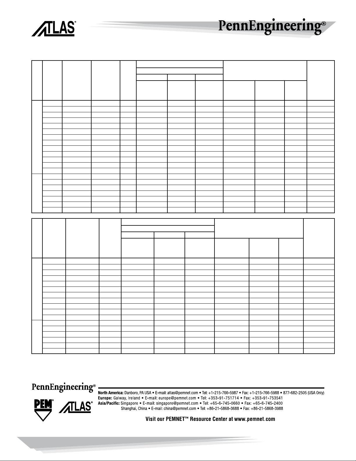
Air Settings Stud
Fastener Material
Complete Steel & Brass Aluminum Monel
Nose Assembly Components
For Internally Threaded Nuts
Series
Part No.
Complete Tool Part No. Dynamic Dynamic Dynamic Part No. For Mandrel Bearing For
Thread Tool Part No. 901, 902 Tool Air Pressure Air Pressure Air Pressure
Complete Nose
Socket Head Set Nose
Size Series 800 903 & 904 RPM Settings Settings Settings Assembly Cap Screw (P/N) Assembly
#4-40 AE801-440 AE901-440 3000 35 - 45 30 - 40 35 - 45 AENP-440 440 x 1.50” AEPB-4 AESNP-440
#6-32 AE801-632 AE901-632 3000 70 - 80 60 - 80 70 - 80 AENP-632 632 x 1.50” AEPB-6 AESNP-632
#8-32 AE801-832 AE901-832 3000 70 - 90 50 - 70 70 - 90 AENP-832 832 x 1.50” AEPB-8 AESNP-832
#10-24 AE802-1024 AE902-1024 1500 60 - 90 40 - 70 60 - 90 AENP-1024 1024 x 1.75” AEPB-10 AESNP-1024
#10-32 AE802-1032 AE902-1032 1500 60 - 90 40 - 70 60 - 90 AENP-1032 1032 x 1.75” AEPB-10 AESNP-1032
1/4-20 AE803-2520 AE903-2520 600 70 - 90 60 - 80 70 - 95 AENP-2520 420 x 1.50” AEPB-25 AESNP-2520
1/4-28 AE803-2528 AE903-2528 600 70 - 90 60 - 80 70 - 95 AENP-2528 428 x 1.50” AEPB-25 AESNP-2528
5/16-18 AE804-3118 AE904-3118 400 70 - 110 60 - 90 70 - 110 AENP-3118 518 x 2.00” AEPB-31 AESNP-3118
5/16-24 AE804-3124 AE904-3124 400 70 - 110 60 - 90 70 - 110 AENP-3124 524 x 2.00” AEPB-31 AESNP-3124
3/8-16 AE804-3716 AE904-3716 400 70 - 110 60 - 90 70 - 110 AENP-3716 616 x 2.00” AEPB-37 AESNP-3716
3/8-24 AE804-3724 AE904-3724 400 70 - 110 60 - 90 70 - 110 AENP-3724 624 x 2.00” AEPB-37 AESNP-3724
1/2-13 AE808-5013 — 275 75 - 120 60 - 90 75 - 110 AENP-5013 813 x 2.50” AEPB-50 AESNP-5013
1/2-20 AE808-5020 — 275 75 - 120 60 - 90 75 - 110 AENP-5020 820 x 2.50” AEPB-50 AESNP-5020
M3 AE801-M3 AE901-M3 3000 2.4 - 3.1 2.1 - 2.7 2.4 - 3.1 AENP-M3 M3 x 40mm AEPB-M3 AESNP-M3
M4 AE801-M4 AE901-M4 3000 2.4 - 3.1 3.4 - 4.8 4.8 - 6.2 AENP-M4 M4 x 40mm AEPB-M4 AESNP-M4
M5 AE802-M5 AE902-M5 1500 4.8 - 5.5 2.7 - 4.8 4.1 - 6.2 AENP-M5 M5 x 45mm AEPB-M5 AESNP-M5
M6 AE803-M6 AE903-M6 600 4.1 - 5.5 4.1 - 5.5 4.8 - 6.5 AENP-M6 M6 x 40mm AEPB-M6 AESNP-M6
BARS PSI
M8 AE804-M8 AE904-M8 400 4.8 - 6.2 4.1 - 6.2 4.8 - 7.5 AENP-M8 M8 x 50mm AEPB-M8 AESNP-M8
M10 AE804-M10 AE904-M10 400 4.1 - 7.5 4.1 - 6.2 4.8 - 7.5 AENP-M10 M10 x 50mm AEPB-M10 AESNP-M10
M12 AE808-M12 — 275 4.1 - 7.5 4.1 - 6.2 5.1 - 7.5 AENP-M12 M12 x 60mm AEPB-M12 AESNP-M12
Air Settings Stud
Fastener Material
Complete Steel & Brass Aluminum Monel
Nose Assembly Components
For Internally Threaded Nuts
Series
Part No.
Tool Part No. Dynamic Dynamic Dynamic Part No. For Mandrel Bearing For
Thread 911, Tool Air Pressure Air Pressure Air Pressure Complete Socket Head Set Nose
Size 912 & 913 RPM Settings Settings Settings Nose Assembly Cap Screw (P/N) Assembly
#4-40 AE911-440 2200 35 - 45 30 - 40 35 - 45 AENP-440 440 x 1.50” AEPB-4 AESNP-440
#6-32 AE911-632 2200 60 - 80 40 - 70 60 - 80 AENP-632 632 x 1.50” AEPB-6 AESNP-632
#8-32 AE911-832 2200 60 - 90 40 - 70 60 - 90 AENP-832 832 x 1.50” AEPB-8 AESNP-832
#10-24 AE911-1024 2200 60 - 90 40 - 70 60 - 90 AENP-1024 1024 x 1.75” AEPB-10 AESNP-1024
#10-32 AE911-1032 2200 60 - 90 40 - 70 60 - 90 AENP-1032 1032 x 1.75” AEPB-10 AESNP-1032
1/4-20 AE12-2520 1100 60 - 90 50 - 80 70 - 95 AENP-2520 420 x 1.50” AEPB-25 AESNP-2520
1/4-28 AE912-2528 1100 70 - 90 50 - 80 70 - 95 AENP-2528 428 x 1.50” AEPB-25 AESNP-2528
5/16-18 AE913-3118 400 70 - 110 60 - 90 70 - 110 AENP-3118 518 x 2.00” AEPB-31 AESNP-3118
5/16-24 AE913-3124 400 70 - 110 60 - 90 70 - 110 AENP-3124 524 x 2.00” AEPB-31 AESNP-3124
3/8-16 AE913-3716 400 70 - 110 60 - 90 70 - 110 AENP-3716 616 x 2.00” AEPB-37 AESNP-3716
3/8-24 AE913-3724 400 70 - 110 60 - 90 70 - 110 AENP-3724 624 x 2.00” AEPB-37 AESNP-3724
M3 AE911-M3 2200 2.4 - 3.1 2.1 - 2.7 2.4 - 3.1 AENP-M3 M3 x 40mm AEPB-M3 AESNP-M3
M4 AE911-M4 2200 2.4 - 3.1 2.7 - 4.8 4.1 - 6.2 AENP-M4 M4 x 40mm AEPB-M4 AESNP-M4
M5 AE911-M5 2200 4.1 - 5.5 2.7 - 4.8 4.1 - 6.2 AENP-M5 M5 x 45mm AEPB-M5 AESNP-M5
M6 AE912-M6 1100 4.1 - 5.5 4.1 - 5.5 4.8 - 7.5 AENP-M6 M6 x 40mm AEPB-M6 AESNP-M6
BARS PSI
M8 AE913-M8 400 4.8 - 6.2 4.1 - 6.2 4.8 - 7.5 AENP-M8 M8 x 50mm AEPB-M8 AESNP-M8
M10 AE913-M10 400 4.1 - 7.5 4.1 - 6.2 4.8 - 7.5 AENP-M10 M10 x 50mm AEPB-M10 AESNP-M10
NOTE: The air supplied to the 800 and 900 series tools should be dry and free of contamination to prevent premature wear and tear of the internal components. We suggest use of a filter, pressure
regulator, and oiler system to be located in close proximity to the tool. All available thread sizes may not be listed. Contact us for availability. Optional mandrel lengths are also available for all product
families. The air settings reported are suggested guidelines. Adjustments may be necessary for your application.
©2012 Rev. 512
 Loading...