

Page 1
I-Fly Wireless Router ADSL
Manual (V1.00)
Page 2

Page 3

COPYRIGHT
The Atlantis Land logo is a registered trademark of Atlants Land SpA. All other names mentioned mat be
trademarks or registered trademarks of their respective owners. Subject to change without notice. No
liability for technical errors and/or omissions. Copyright 2002 by this company.
DISCLAIMER
This company makes no representations or warranties, either expressed or implied, with respect to the
contents hereof and specifically disclaims any warranties, merchantability or fitness for any particular
purpose. Any software described in this manual is sold or licensed "as is". Should the programs prove
defective following their purchase, the buyer (and not this company, its distributor, or its dealer) assumes
the entire cost of all necessary servicing, repair, and any incidental or consequential damages resulting
from any defect in the software. Further, this company reserves the right to revise this publication and to
make changes from time to time in the contents hereof without obligation to notify any person of such
revision or changes.
Page 4

Page 5

Table of Contents
CHAPTER 1........................................................................................................................... 1
1.1 AN OVERVIEW OF ADSL MODEM/ROUTER ................................................................................................. 1
1.2 PACKAGE CONTENTS.................................................................................................................................... 2
1.3 ADSL MODEM/ROUTER FEATURES ............................................................................................................. 2
1.4 HARDWARE INDICATORS.............................................................................................................................. 3
Front Panel..................................................................................................................................................... 3
LED Indicators ............................................................................................................................................... 3
Rear Panel...................................................................................................................................................... 4
1.5 HARDWARE INSTALLATION......................................................................................................................... 6
CHAPTER 2........................................................................................................................... 7
2.1 CAUTIONS FOR USING ADSL MODEM/ROUTER........................................................................................... 7
2.2 CABLING ....................................................................................................................................................... 7
CHAPTER 3........................................................................................................................... 9
3.1 INSTALLING THE USB DRIVER ..................................................................................................................... 9
3.1.1 For Windows XP.................................................................................................................................... 9
3.1.2 For Windows 2000 .............................................................................................................................. 13
3.1.3 For Windows Me ................................................................................................................................. 15
3.1.4 For Windows 98 .................................................................................................................................. 17
3.2 CONFIGURING THE NETWORK PROPERTIES................................................................................................ 19
3.2.1 For Windows XP.................................................................................................................................. 20
3.2.2 For Windows 2000 .............................................................................................................................. 22
3.2.3 For Windows 95/98/Me ....................................................................................................................... 24
3.2.4 For Windows NT4.0............................................................................................................................. 26
3.3 FACTORY DEFAULT SETTINGS.................................................................................................................... 27
3.2.1 Password ............................................................................................................................................. 27
3.2.2 LAN and WAN Port Addresses ............................................................................................................ 27
3.4 INFORMATION FROM ISP ............................................................................................................................ 28
3.5 CONFIGURING WITH WEB BROWSER .......................................................................................................... 29
3.5.1 Status – Home Page............................................................................................................................. 31
3.5.2 Status – ADSL Status........................................................................................................................... 31
3.5.3 Status – LAN........................................................................................................................................ 32
3.5.4 Configuration – WAN Configuration .................................................................................................. 32
3.5.5 Configuration – LAN Configuration ................................................................................................... 35
3.5.6 Configuration – NAT Configuration ................................................................................................... 37
3.5.7 Configuration – Virtual Server Configuration .................................................................................... 39
3.5.8 Configuration – Bridge Filtering Configuration................................................................................. 40
3.5.9 Configuration – DNS Configuration ................................................................................................... 43
3.5.10 Configuration – Save Settings ........................................................................................................... 44
3.5.11 Admin Privilege – WAN Status.......................................................................................................... 44
3.5.12 Admin Privilege – PPP Status........................................................................................................... 45
3.5.13 Admin Privilege – TCP Status........................................................................................................... 46
3.5.14 Admin Privilege – Route Table.......................................................................................................... 47
3.5.15 Admin Privilege – Learned ( Bridge ) MAC Table............................................................................ 48
3.5.16 Admin Privilege – ADSL Configuration............................................................................................ 48
3.5.17 Admin Privilege – RIP Configuration ............................................................................................... 49
3.5.18 Admin Privilege – Password Configuration...................................................................................... 50
i
Page 6

I-Fly Wireless Router ADSL
3.5.19 Admin Privilege – Miscellaneous Configuration .............................................................................. 50
3.5.20 Admin Privilege – Reset to Factory Default...................................................................................... 52
3.5.21 Admin Privilege – Diagnostic Test.................................................................................................... 52
3.5.22 Admin Privilege – Code Image Update............................................................................................. 55
3.5.23 Admin Privilege – Network Code Image Update ..............................................................................55
3.5.24 Admin Privilege – System Log........................................................................................................... 56
CHAPTER 4......................................................................................................................... 57
PROBLEMS STARTING UP THE ADSL ROUTER................................................................................................. 57
PROBLEMS WITH THE WAN INTERFACE .......................................................................................................... 57
PROBLEMS WITH THE LAN INTERFACE............................................................................................................ 57
PROBLEMS CONNECTING TO A REMOTE NODE OR ISP .................................................................................... 58
APPENDIX............................................................................................................................. 59
APPENDIX............................................................................................................................. 60
APPENDIX............................................................................................................................. 64
A02-WRA-11B/M2 (June 2003) V1.00
ii
Page 7

Chapter 1
Introduction
1.1 An Overview of I-Fly Wireless Router ADSL
ADSL Modem/Router provides a high-speed Ethernet port and an USB (Universal Serial Bus) port for
high-speed Internet browsing. It can support downstream transmission rates of up to 8Mbps and upstream
transmission rates of up to 1024Kbps. It is compliant with Multi-Mode standard (ANSI T1.413, Issue 2;
G.dmt (G.992.1); G.lite (G992.2); G.hs (G994.1)).
The product supports PPPoA (RFC 2364 – PPP (Point-to-Point Protocol) over ATM Adaptation Layer 5),
RFC 1483 encapsulation over ATM (bridged or routed), PPP over Ethernet (RFC 2516), and IPoA
(RFC1577) to establish a connection with ISP. The product also supports VC-based and LLC-based
multiplexing.
It is the perfect solution to connect a small group of PCs to a high-speed broadband Internet connection.
Multi-users can have high-speed Internet access simultaneously.
This product also serves as an Internet firewall, protecting your network from being accessed by outside
users. Not only provide the natural firewall function (Network Address Translation, NAT), it also
provides rich firewall features to secure user’s network. All incoming data packets are monitored and
filtered. Besides, it can also be configured to block internal users from accessing to the Internet.
The product provides two levels of security support. First, it masks LAN users’ IP addresses which are
invisible to outside users on the Internet, making it much more difficult for a hacker to target a machine
on your network. Secondly, it can block and redirect certain ports to limit the services that outside users
can access. For example, to ensure that games and other Internet applications will run properly, user can
open some specific ports for outside users to access internal services in network.
Integrated DHCP (Dynamic Host Control Protocol) services, client and server, allow multiple users to get
their IP addresses automatically on boot up from the product. Simply set local machines as a DHCP
client to accept a dynamically assigned IP address from DHCP server and reboot. Each time local
machine is powered up; the router will recognize it and assign an IP address to instantly connect it to the
LAN.
For advanced users, Virtual Service function allows the product to provide limited visibility to local
machines with specific services for outside users. An ISP (Internet Service Providers) provided IP
address can be set to the product and then specific services can be rerouted to specific computers on the
local network. For instance, a dedicated web server can be connected to the Internet via the product and
then incoming requests for HTML that are received by the product can be rerouted to the dedicated local
web server, even though the server now has a different IP address. In this example, the product is on the
Internet and vulnerable to attacks, but the server is protected.
Virtual Server can also be used to re-task services to multiple servers. For instance, the product can be set
to allow separated FTP, Web, and Multiplayer game servers to share the same Internet-visible IP address
while still protecting the servers and LAN users from hackers.
1
Page 8

I-Fly Wireless Router ADSL
1.2 Package Contents
1. I-Fly Wireless Router ADSL
2. One CD-ROM containing the driver and online manual
3. One Quick Start Guide
4. One RJ-11 ADSL/telephone cable
5. One CAT-5 LAN cable
6. One USB cable
7. One power adapter
1.3 ADSL Modem/Router Features
ADSL Modem/Router provides the following features:
ADSL Multi-Mode Standard: Supports downstream transmission rates of up to 8Mbps and upstream
transmission rates of up to 1024Kbps. It is compliant with Multi-Mode standard (ANSI T1.413, Issue 2;
G.dmt (G.992.1); G.lite (G992.2); G.hs (G994.1)).
Multi-Protocol to Establish A Connection: Supports PPPoA (RFC 2364 - PPP over ATM Adaptation
Layer 5), RFC 1483 encapsulation over ATM (bridged or routed), PPP over Ethernet (RFC 2516) and
IPoA (RFC1577) to establish a connection with ISP. The product also supports VC-based and LLC-based
multiplexing.
Wireless (IEEE802.11b):This is the device for a total freedom of movement without losing the
connection.
Network Address Translation (NAT): Allows multi-users to access outside resource such as Internet
simultaneously with one IP address/one Internet access account. Besides, many application layer gateway
(ALG) are supported such as web browser, ICQ, FTP, Telnet, E-mail, News, Ping and others.
Domain Name System (DNS) relay: Provides an easy way to map the domain name (a friendly name for
user such as www.yahoo.com
IP address. Then every DNS conversion request packet from the PC to this router will be forwarded to the
real DNS in outside network. After the router gets the reply, then forwards it back to the PC.
PPP over Ethernet (PPPoE): Provides embedded PPPoE client function to establish a connection. Users
can get greater access speed without changing the operation concept, sharing the same ISP account and
paying for one access account. No PPPoE client software is required for local computer. The Automatic
Reconnect and Disconnect Timeout (Idle Timer) functions are provided, too.
Virtual Server: User can specify some services to be visible from outside users. The router can detect
incoming service request and forward it to the specific local computer to handle it. For example, user can
assign a PC in LAN acting as WEB server inside and expose it to the outside network. Outside user can
browse inside web server directly while it is protected by NAT. A DMZ host setting is also provided to a
local computer exposed to the outside network, Internet.
) and IP address. When local machine sets its DNS server with this router’s
Bridge Filtering: Filters the packet based on MAC address. It will increase the performance in LAN and
WAN, also provide a higher-level security control.
Dynamic Host Control Protocol (DHCP) client and server: In the WAN site, the DHCP client can get
an IP address from the Internet Server Provider (ISP) automatically. In the LAN site, the DHCP server
2
Page 9
Chapter 1 Introduction
can allocate multiple clients IP addresses and distribute them including IP address, subnet mask as well as
DNS IP address to local computers. It provides an easy way to manage the local IP network.
Web based GUI: Supports user-friendly web based GUI for configuration and management.
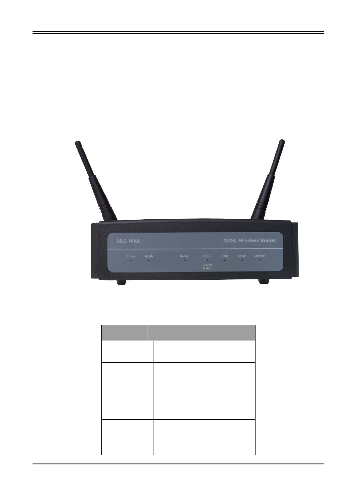
1.4 Hardware Indicators
Front Panel
Place the Router in a location that permits an easy view of the LED indicators shown in the front panel
diagram below.
LED Indicators
The LED Indicators read as follows:
Port Information
1 POWER
2 WLAN
3 READY
4 ADSL
Lit green when power adapter is
connected.
Check wireless device the
WLAN Indicator flash green.
System status indicators when
blinking indicate system is alive.
When lit, it indicates that the
ADSL (Line) port is connected to
the DSLAM and working
properly.
3
Page 10

I-Fly Wireless Router ADSL
5 RxD
The RXD Indicator light green
when data traffic is receiving
from the WAN port, the LED
will rapidly flash green during
data transfer
6 10/100
The 10/100 Indicator lights green
when data traffic is data
transfer.[On =100Mbps,Off
=10Mbps]
The LAN LINK Indicator lights
green when your ROUTER is
connected to your
PC or Ethernet LAN.
The LAN ACT Indicator lights
7 Link/Act
green when data traffic is passing
through the
Ethernet port, the LED will
rapidly flash green during data
transfer
Rear Panel
The rear panel of the Router provides access to the DC power adapter, one USB connection, four LAN
connections, one WAN connection and power on/off switch.
4
Page 11
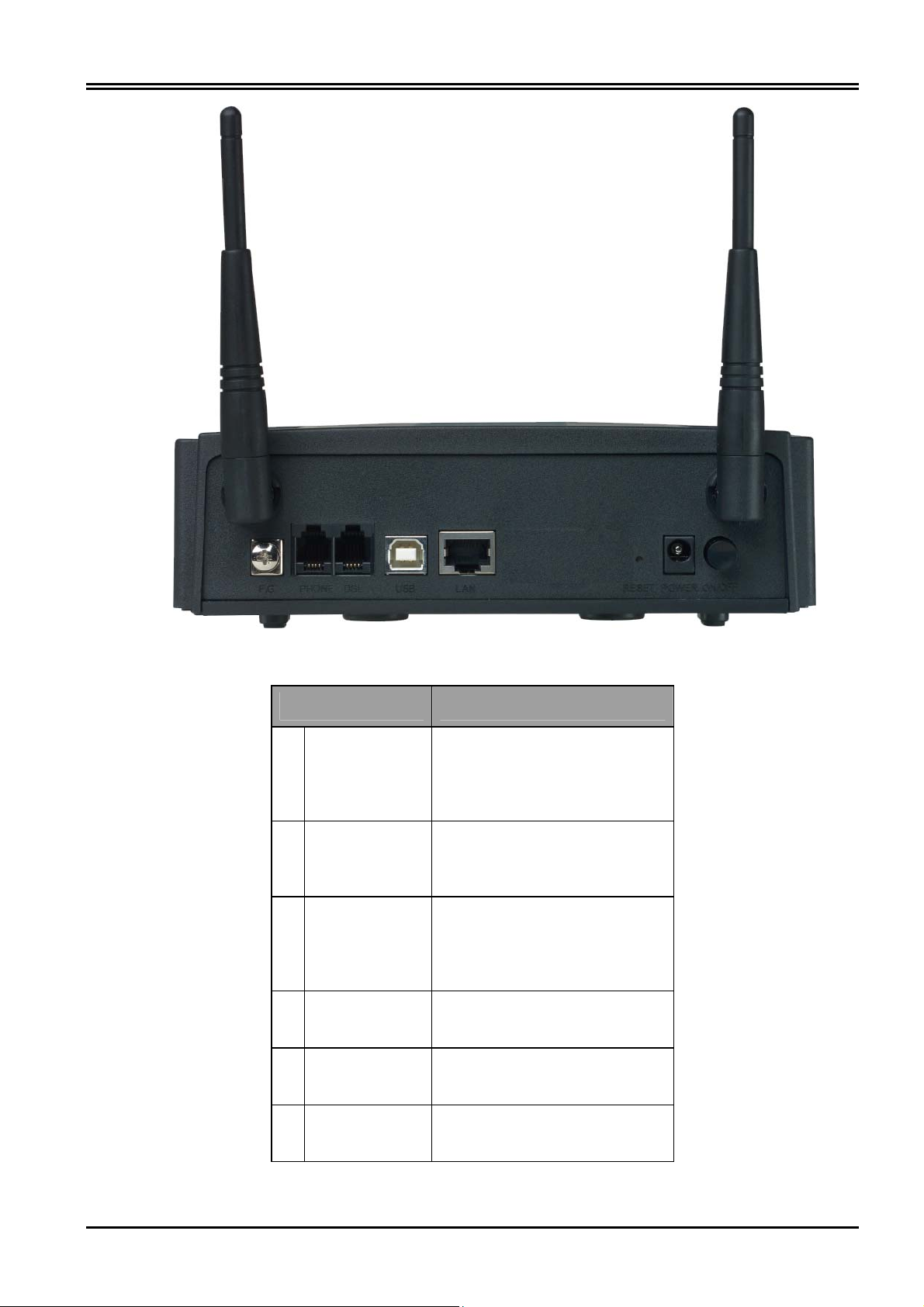
Chapter 1 Introduction
Port Meaning
1 Line(RJ11) Connect the supplied RJ-11
cable to this port when
connecting to the
ADSL/telephone network.
2 USB Connect the USB cable to this
port when Upgrading Firmware
or connecting to PC
3 LAN
4 Reset Press it (10 sec) to restore the
5 POWER
(jack)
Connect a straight or crossover
Ethernet cable to this port when
connecting to PCs or Switch in
the network
factory default setting back
Connect the supplied power
adapter to this jack
6 POWER
Switch
Switch On/Off the device
5
Page 12

I-Fly Wireless Router ADSL
1.5 Hardware Installation
Power on
Connect the Adapter to power inlet and turn the power switch on, this product will enter a self-test phase.
When it is in the self-test phase, the indicators READY LED will be lighted ON for about 8 seconds, and
the READY LED will be flashed to indicate that the self-test phase has finished. Finally, the READY
LED will be flashed to indicate that router is in normal operation.
ADSL connection
Simply plug one end of the cable into the ADSL port (RJ-11 receptacle) on the rear panel of the
Router and insert the other end into splitter .
Connect Router to LAN
Prepare an Ethernet cable to connect Router to Hub or Switch of your LAN. You can connect
Router to your PC directly by crossover Ethernet cable.
6
Page 13

Chapter 2
Using ADSL Modem/Router
2.1 Cautions for Using ADSL Modem/Router
Do not place the router under high humidity and high temperature.
Do not use the same power source for the device with other equipment.
Do not open or repair the case yourself. If the device is too hot, turn off the power
immediately and have a qualified serviceman repair it.
Place the product on the stable surface.
Only use the power adapter that comes with the package.
2.2 Cabling
Through USB Port
The product can be used as a Network Adapter on your PC. That means you do not have to install a
network adapter first on your PC before connecting the ADSL Modem/Router. Just connect the supplied
USB cable to the USB port of the ADSL Modem/Router and connect the other end to the PC.
Make sure that your ADSL Modem/Router and PC are turned on. On the front of the product is a bank of
LEDs. As a first check, please verify that the PWR, WLAN and ADSL LEDs are lit and READY
blinking.
So long as the cables are connected and the LEDs are lit normally, follow section “3.1 Installing the
USB Driver” below to setup this device.
Through Ethernet Port
The product’s LAN port is wired just like a Network Adapter’s port. From the product directly to a PC,
the cable should be an Ethernet crossover cable. From the product to a hub or switch, the cable should be
an Ethernet straight through cable to a normal hub/switch port, or an Ethernet crossover cable to an
uplink port.
The most common problem associated with Ethernet is bad cabling or ADSL line. Make sure that all
connected devices are turned on. On the front of the product is a bank of LEDs. As a first check, please
verify that the PWR, WAN, LAN and ADSL SYN LEDs are lit. If they are not, verify that you are using
the proper cables.
So long as the cables are connected and the LEDs are lit normally, follow section “3.2 Configuring the
Network Properties” below to modify the network settings.
7
Page 14

I-Fly Wireless Router ADSL
Since the product cannot auto-detect whether your cable is correct or not, please make sure
you are using the right cable to a PC or a Hub.
8
Page 15
Chapter 3
Installation and Configuration
3.1 Installing the USB Driver
If you connect the ADSL Modem/Router through USB port, for the first time the USB cable is connected
to the PC, Windows will automatically detect the device. Follow the steps to install the USB driver.
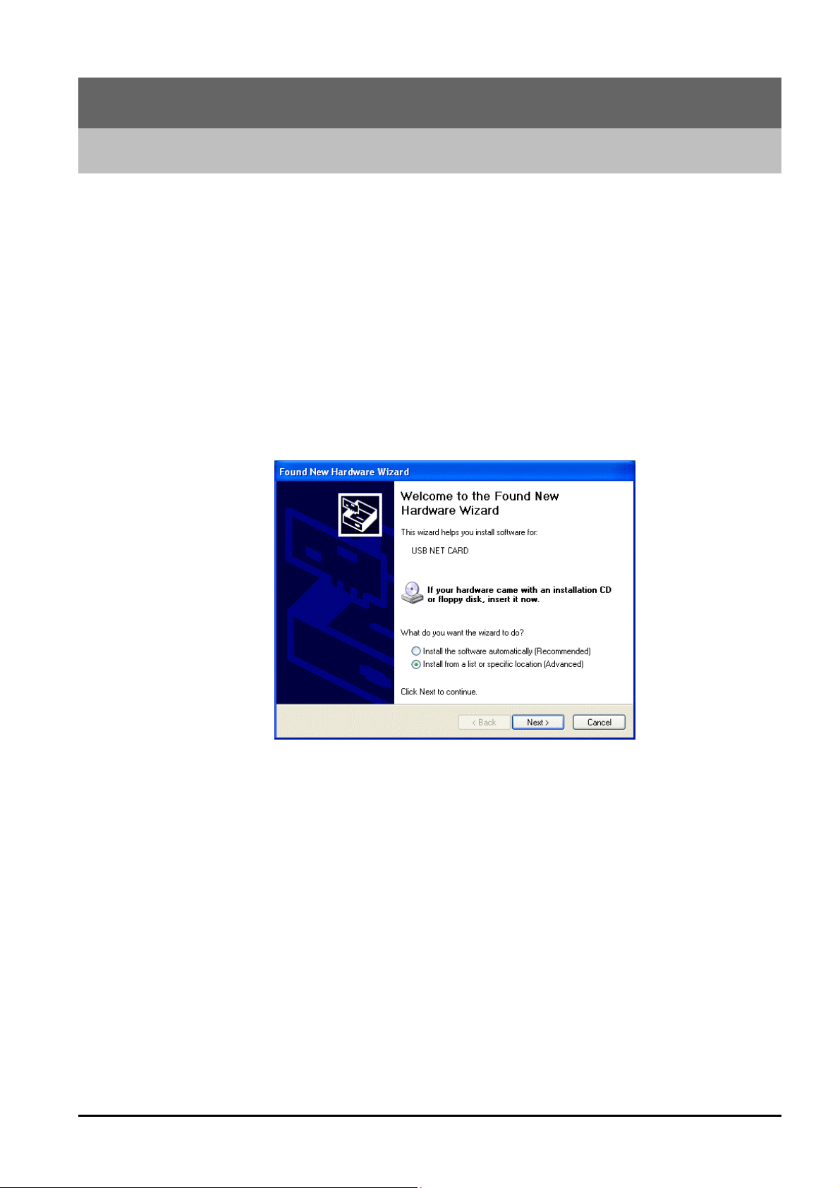
3.1.1 For Windows XP
1. When Windows tells you that the new device has been detected, select “Install from a list or specific
location” and click “Next >”.
9
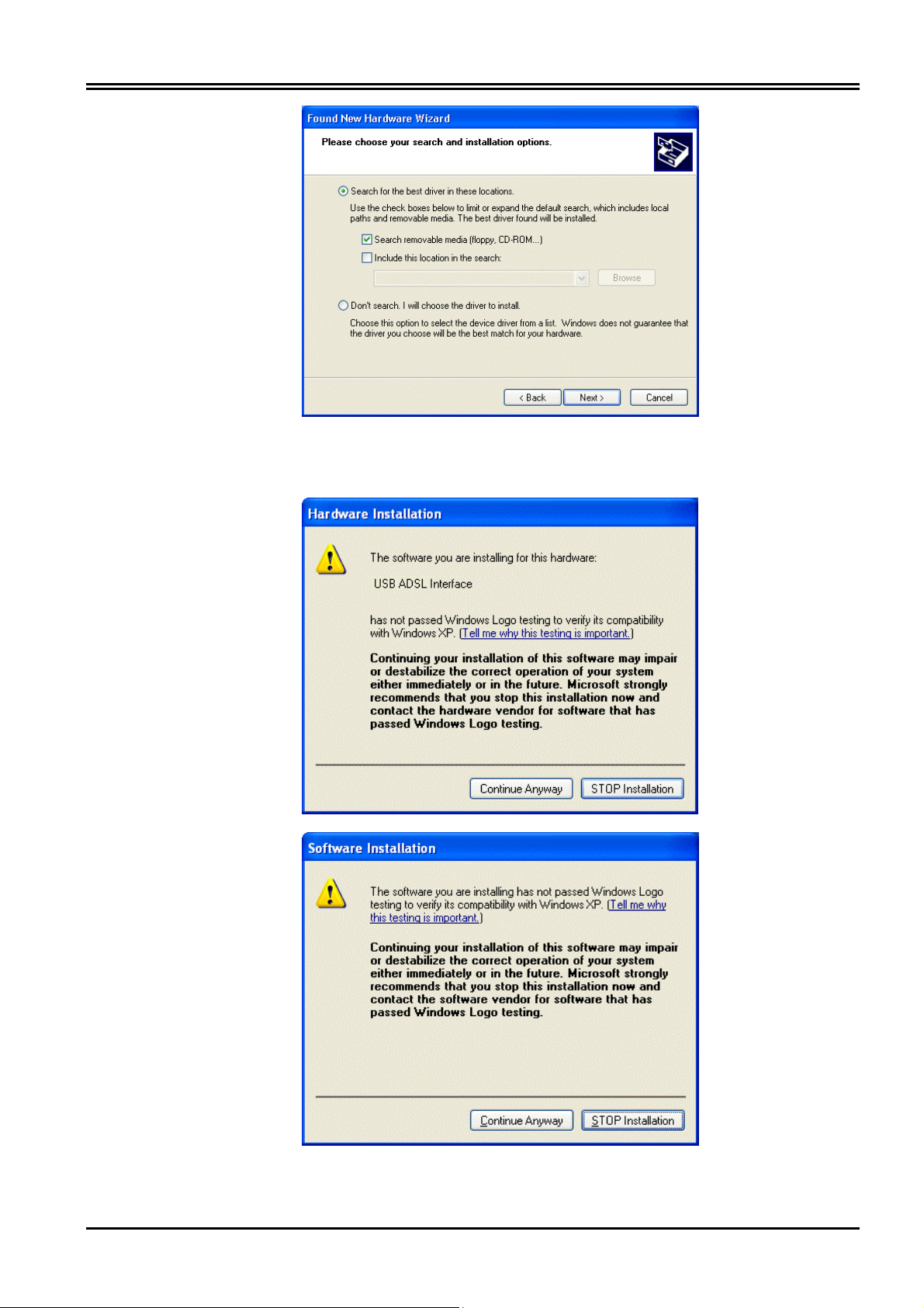
2. Insert the installation CD into the CD-ROM drive. Check “Include this location for the search” and
click “Browse”. (the folder CD:\A02-WRA-11B\Driver). Then, it takes seconds to search and install
the software.
Page 16
I-Fly Wireless Router ADSL
3. When windows titled “Hardware Installation” or “Software Installation” appears, press “Continue
Anyway” to go on.
10
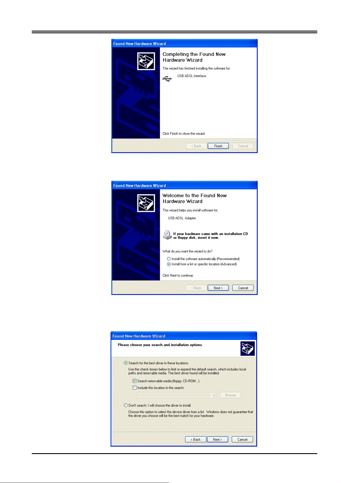
4. Then, click “Finish”.
Page 17
Chapter 3 Installation and Configuration
5. After a few moments, Windows will show the new device, USB ADSL Adapter, has been detected.
Select “Install from a list or specific location”. Click “Next >”.
6. Click “Next >” when the following figure appears. Check “Include this location for the search” and click
“Browse”. (the folder CD:\A02-WRA-11B\Driver). Then, it takes seconds to search and install the
software.
11
Page 18
I-Fly Wireless Router ADSL
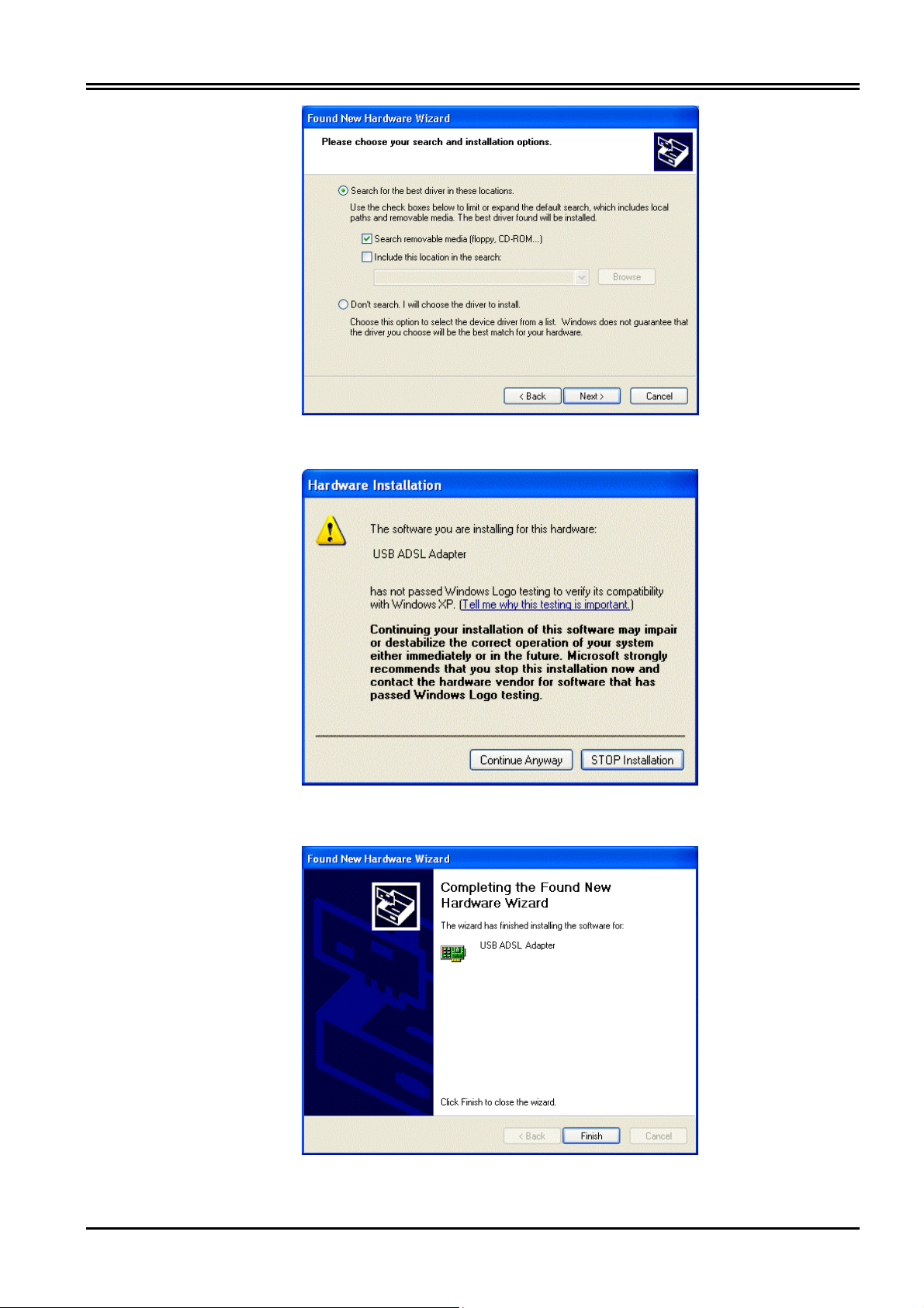
7. When windows titled “Hardware Installation” appears, press “Continue Anyway”.
8. Then, click “Finish” to end the installation.
12
Page 19
Chapter 3 Installation and Configuration
9. After installing the driver, follow the section “3.2 Configuring the Network Properties” below to
modify the network settings on your PC.
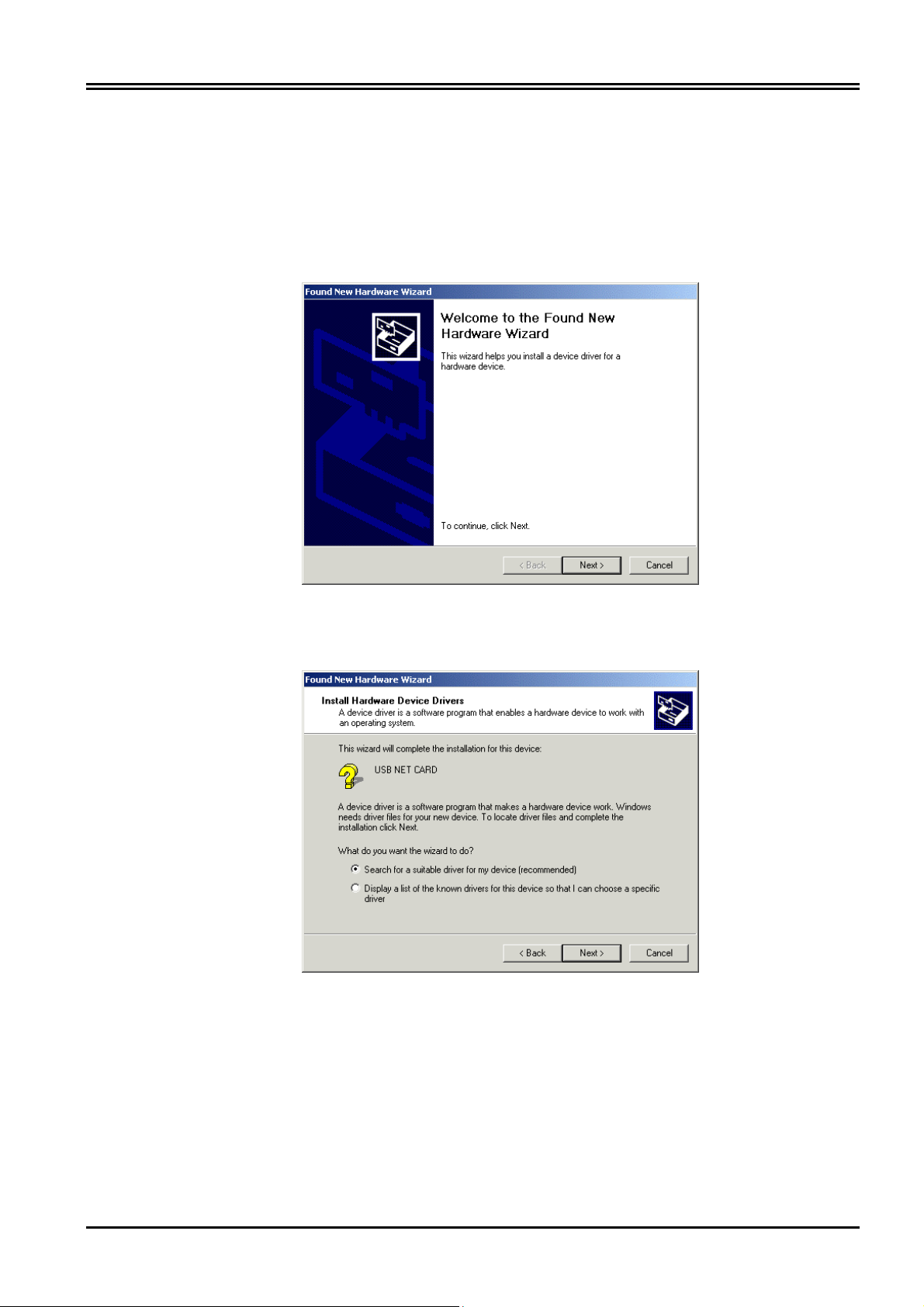
3.1.2 For Windows 2000
1. When Windows tells you that the new device has been detected, click “Next >” to continue.
2. Select “Search for a suitable driver for my device”. Click “Next>”. Then, insert the installation CD into
the CD-ROM drive.
3. In next window, check “Specify a location” and click “Next>”. Click “ Browse “ and specify the folder
CD:\A02-WRA-11B\Driver\.
13
Page 20

I-Fly Wireless Router ADSL
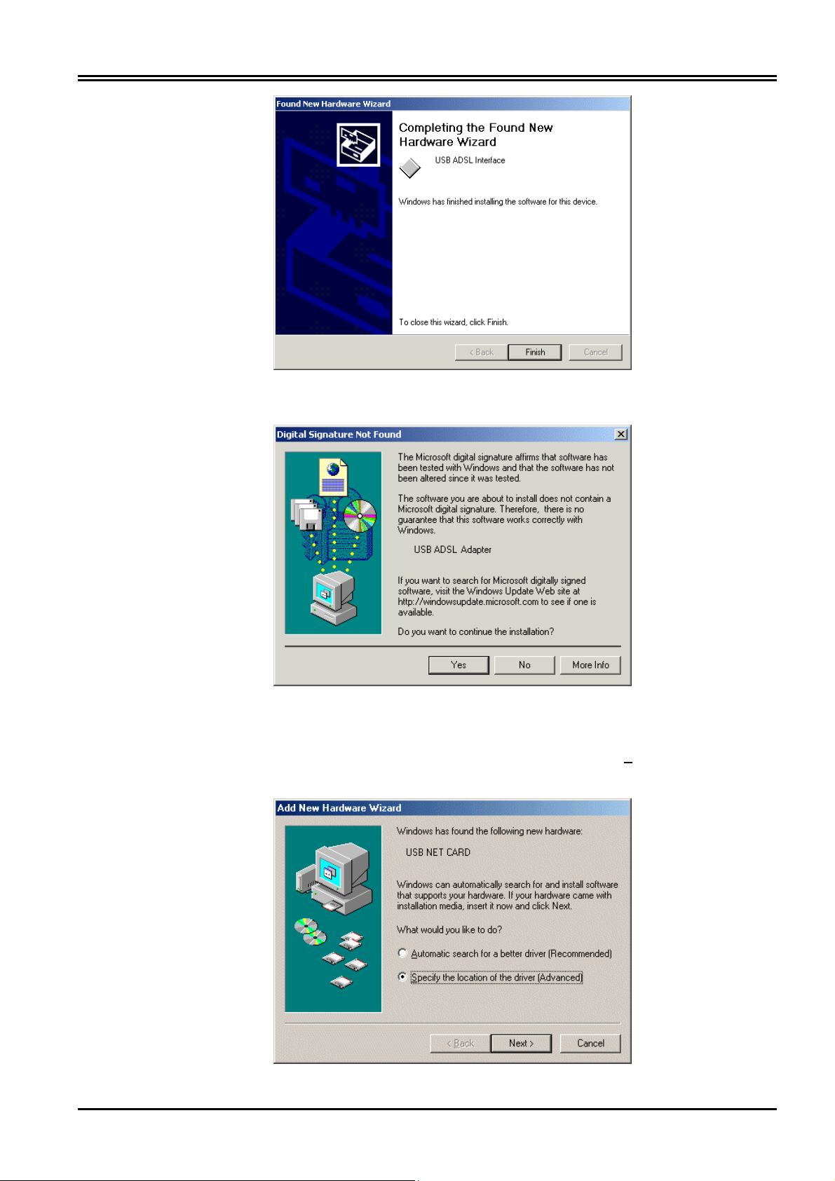
4. Continuing through the Wizard, click the “Next >” button.
5. When window titled “Digital Signature Not Found” appears, press “Yes” to continue the installation.
6. Press “Finish”.
14
Page 21
Chapter 3 Installation and Configuration
7. If the following window “Digital Signature Not Found” appears, press “Yes” to end the installation.
3.1.3 For Windows Me
1. When Windows tells you that the new device has been detected. Select “Specify the location of the
driver” and click “Next >”.
15
Page 22

I-Fly Wireless Router ADSL
2. Insert the installation CD into the CD-ROM drive and check “Specify a Location”. Click “ Browse
“ and specify the folder CD:\A02-WRA-11B\Driver\. Click “Next>” to continue.
3. Continuing through the Wizard, click the “Next >” button.
16
4. Continuing through the Wizard, Windows will start copying files to your system. Then, click
“Finish”.
Page 23

Chapter 3 Installation and Configuration
3.1.4 For Windows 98
1. When Windows tells you that the new device has been detected, click “Next >”.
2. In the next window, select “Search for the best driver for your device” and click “Next >”.
3. Insert the installation CD into the CD-ROM drive and check “Specify a l
to specify the driver directory such as D:\A02-WRA-11B\Driver\. Click “OK” and then “Next>” to
continue.
ocation”. Click “Browse…”
17
Page 24

I-Fly Wireless Router ADSL
18
4. Continuing through the Wizard, click the “Next >” button.
5. Windows will start copying files to your system. Then, click “Finish”.
Page 25

Chapter 3 Installation and Configuration
6. You will see the following screen prompting for the path of the Windows source files. Please
specify a location. Click “OK”.
3.2 Configuring the Network Properties
This section describes the configuration required by LAN-attached PCs that communicate with the ADSL
Modem/Router, either to configure the device, or for network access. These PCs must have an Ethernet
interface installed properly to be connected to the ADSL Modem/Router either directly or through an
external device, hub. PC must have TCP/IP installed and configured to obtain an IP address through a
DHCP server or a fixed IP address that must be in the same subnet of the I-Fly Wireless Router ADSL .
The default IP address of the ADSL Modem/Router is 10.0.0.2 and subnet mask is 255.0.0.0. The best
and easy way is to configure the PC to get an IP address from the ADSL Modem/Router.
Please follow the steps below for PC’s network environment installation. Before taking the first step,
please check your PC’s network components. If your PC connects to the ADSL Modem/Router through
USB port, the TCP/IP protocol stack must be installed. If your PC connects the ADSL Modem/Router
through Ethernet port, the TCP/IP protocol stack and Ethernet network adapter must be installed. If not,
please refer to MS Windows relative manuals.
19
Page 26

I-Fly Wireless Router ADSL
Any TCP/IP capable workstation can be used to communicate with or through the
ADSL Modem/Router. To configure other types of workstations, please consult the
manufacturer’s documentation.
3.2.1 For Windows XP
1. Go to Start / Control Panel (in
Classic View). In the Control Panel,
double-click on Network
Connections.
2. Double-click Local Area
Connection.
3. In the LAN Area Connection Status
window, click Properties.
20
Page 27

4. Select Internet Protocol (TCP/IP)
and click Properties.
Chapter 3 Installation and Configuration
5. Select the Obtain an IP address
automatically and the Obtain DNS
server address automatically radio
buttons.
6. Click OK to finish the configuration.
21
Page 28

I-Fly Wireless Router ADSL
3.2.2 For Windows 2000
1. Go to Start / Settings / Control
Panel. In the Control Panel, doubleclick on Network and Dial-up
Connections.
2. Double-click LAN Area Connection.
3. In the LAN Area Connection Status
window, click Properties.
22
Page 29

4. Select Internet Protocol (TCP/IP)
and click Properties.
Chapter 3 Installation and Configuration
5. Select the Obtain an IP address
automatically and the Obtain DNS
server address automatically radio
buttons.
6. Click OK to finish the configuration.
23
Page 30

I-Fly Wireless Router ADSL
3.2.3 For Windows 95/98/Me
1. Go to Start / Settings / Control
Panel. In the Control Panel, double-
click on Network and choose the
Configuration tab.
2. Select TCP / IP -> NE2000
Compatible, or the name of any
Network Interface Card (NIC) in your
PC.
3. Click Properties.
24
Page 31

4. Select the IP Address tab. In this
page, click the Obtain an IP address
automatically radio button.
Chapter 3 Installation and Configuration
5. Then select the DNS Configuration
tab.
6. Select the Disable DNS radio button
and click “OK” to finish the
configuration.
25
Page 32

I-Fly Wireless Router ADSL
3.2.4 For Windows NT4.0
1. Go to Start / Settings / Control
Panel. In the Control Panel, double-
click on Network and choose the
Protocols tab.
2. Select TCP/IP Protocol and click
Properties.
3. Select the Obtain an IP address
from a DHCP server radio button
and click OK.
26
Page 33

Chapter 3 Installation and Configuration
3.3 Factory Default Settings
Before you configure this device, you need to know the following default settings.
1. Web Configurator
Password: There are two levels of password protection, Administrator Level and User Level.
User Name Password
Administrator Level
User Level
2. Device IP Network settings in LAN site
IP Address: 10.0.0.2
Subnet Mask: 255.0.0.0
3. ISP setting in WAN site
Virtual Circuit 0: PPPoA VCMux
Virtual Circuit 1 ~ 7: 1483 Bridged IP LLC
4. DHCP server
DHCP server is enabled.
IP address pool from IP Address: 10.0.0.4 to IP Address: 10.0.0.15
admin epicrouter
user password
3.2.1 Password
There are two levels of password protection. The first level is for administrator and the second
one is for user.
If you want to configure the device with administrator level, type admin in the username field
and epicrouter in the password field. If you want to configure the device with the user level,
type user in the username field and password in the password field. Then, click “OK” to log in.
You can modify these passwords for security and management purpose.
If you ever forget the password to log in, you should contact the dealer where you bought this
product.
3.2.2 LAN and WAN Port Addresses
The parameters of LAN and WAN ports are pre-set in the factory. The default values are shown below.
LAN Port WAN Port
IP address
Subnet Mask
DHCP server function
10.0.0.2
255.0.0.0
Enabled
PPPoA with VCMux
27
Page 34

I-Fly Wireless Router ADSL
IP addresses for
distribution to PCs
12 IP addresses continuing from 10.0.0.4
through 10.0.0.15
(Actually, it can support up to 253 users.)
3.4 Information from ISP
Before beginning the configuration of the Router you have to know the parameters of your subscription
ADSL.
There are five ways ― PPPoE, PPPoA, RFC1483 routed, IPoA, RFC1483 Bridge― for the device to
have a public IP address and then to access Internet. You have to check with your ISP about which way is
adopted.
VPI/VCI: Consult the telephone company to get the Virtual Path Identifier (VPI) and Virtual Channel
Identifier (VCI) numbers. The valid range for the VPI is 0 to 255 and for the VCI is 32 to 65535. The
default value VPI is 0 and VCI is 32.
For BT (VPI=0, VCI=38) and for KC ((VPI=1, VCI=50).
NAT: The NAT feature allows multiple-user Internet access for the cost of a single IP account. If you
need to have a public server or a public network, NAT has to be disabled.
Encapsulation Method: Be sure to use the encapsulation method (LLC/SNAP or VC MUX) required by
your ISP.
Gather the information as illustrated in the following table and keep it for reference. Before start
configuring this device, you have to check what kind of service is provided by your ISP, including the
following:
1. PPPoE VC-Mux
2. PPPoE LLC
3. PPPoE None
4. PPPoA VC-Mux
5. PPPoA LLC
6. 1483 Bridged IP VC-Mux
7. 1483 Bridged IP LLC
8. 1483 Routed IP VC-Mux
9. 1483 Routed IP LLC
10. Classical IP over ATM
11. Native ATM
Gather the information as illustrated in the following table and keep it for reference.
28
Page 35

Chapter 3 Installation and Configuration
PPPoE VC-Mux VPI/VCI, Service Name, Username, Password, and Domain Name
System (DNS) IP address (it can be automatically assigned from
ISP or be set fixed).
PPPoE LLC VPI/VCI, Service Name, Username, Password, and Domain Name
System (DNS) IP address (it can be automatically assigned from
ISP or be set fixed).
PPPoE None VPI/VCI, Service Name, Username, Password, and Domain Name
System (DNS) IP address (it can be automatically assigned from
ISP or be set fixed).
PPPoA VC-Mux VPI/VCI, Username, Password, and Domain Name System (DNS)
IP address (it can be automatically assigned from ISP or be set
fixed).
PPPoA LLC VPI/VCI, Username, Password, and Domain Name System (DNS)
IP address (it can be automatically assigned from ISP or be set
fixed).
1483 Bridged IP LLC VPI/VCI
1483 Bridged IP VC-Mux VPI/VCI
1483 Routed IP LLC VPI/VCI, IP address, Subnet mask, Gateway address, and Domain
Name System (DNS) IP address (it is fixed IP address).
1483 Routed IP VC-Mux VPI/VCI, IP address, Subnet mask, Gateway address, and Domain
Name System (DNS) IP address (it is fixed IP address).
Classical IP over ATM VPI/VCI, IP address, Subnet mask, Gateway address, and Domain
Name System (DNS) IP address (it is fixed IP address).
3.5 Configuring with Web Browser
The ADSL Modem/Router can be configured with your Web browser. The web browser is included as a
standard application in following operation systems, UNIX, Linux, Mac OS, Windows
95/98/NT/2000/Me/XP, etc. The product provides a very easy and user-friendly interface for
configuration.
Open the web browser, enter the local port IP address of the ADSL Router, which default at 10.0.0.2 ,
and click “Go” to get the login page.
29
Page 36

I-Fly Wireless Router ADSL
There are two levels of password protection. The first level is for administrator and the second
one is for user.
If you want to configure the device with administrator level, type admin in the username field
and epicrouter in the password field.
If you want to configure the device with the user level, type user in the username field and
password in the password field.
30
Page 37

Chapter 3 Installation and Configuration
Then, click “OK” to log in. You can modify these passwords for security and management
purpose.
At the configuration homepage, the left navigation pane where bookmarks are provided links you directly
to the desired setup page. Click on the desired item to expand the page in the main navigation pane.
3.5.1 Status – Home Page
This screen contains information of the software version of your device and some settings, such as IP
Address, Subnet Mask, and MAC Address of the WAN and LAN connections.
Click Show Advanced settings.
3.5.2 Status – ADSL Status
Displays the status of your ADSL connection. It will refresh every two seconds.
31
Page 38

I-Fly Wireless Router ADSL
3.5.3 Status – LAN
Displays the status of your Local Area Network (LAN) connection.
3.5.4 Configuration – WAN Configuration
The screens below contain settings for the WAN interface toward Internet.
32
Page 39

Chapter 3 Installation and Configuration
System Wide Settings
Default Gateway: Enter the gateway address provided by your ISP.
Per VC Settings
There are eight Virtual Circuit (VC) for you to set, from VC 0 to VC 7. Before you make the settings,
please scroll down to the button of the page and select the item of Virtual Circuit you want to configure.
Then, press the Execute button.
33
Page 40

I-Fly Wireless Router ADSL
Enabled? : Select Yes if you want to enable the settings of this VC or select No if you want to disable
the settings of this VC.
VPI: Consult the telephone company to get the Virtual Path Identifier (VPI) number. The default value is
0.
VCI: Consult the telephone company to get the Virtual Channel Identifier (VCI) number. The default
value is 32.
Static IP Address: Enter the information provided by your ISP.
Subnet Mask: Enter the information provided by your ISP.
ATM
Service Category: Select UBR or CBR.
Bandwidth: Enter the bandwidth.
ENCAPSULATION
There are eleven ways ― PPPoE VC-Mux, PPPoE LLC, PPPoE None, PPPoA VC-Mux, PPPoA LLC,
1483 Bridged IP VC-Mux, 1483 Bridged IP LLC, 1483 Routed IP VC-Mux, 1483 Routed IP LLC,
Classical IP over ATM, Native ATM ― for the device to have a public IP address and then to access
Internet. You have to check with your ISP about which way is adopted.
BRIDGE
If you set this device to be bridge mode, select Enable; if not, please select Disable.
IGMP
You can Enable or Disable this function.
PPP
If your encapsulation is set to be PPPoE or PPPoA, the following fields must be entered.
Service Name: This item is for identification purpose. If it is required, your ISP will provide you the
information. Maximum input is 31 alphanumeric characters.
Username: Enter the username provided by your ISP.
Password: Enter the password provided by your ISP.
Disconnect Timeout
line for a predetermined period of time. You can input any number from 0 to 32767. The default value is
0 seconds.
Authentication: Default at “Auto”.
Automatic Reconnect: Check to enable this device to automatically re-establish the PPPoE session when
disconnected by ISP.
seconds: Auto-disconnect the ADSL Router when there is no activity on the
DHCP
34
Page 41

Chapter 3 Installation and Configuration
DHCP client enable: Check to enable the DHCP client function if you want the device to get an IP
address automatically from your ISP.
Host Name: Enter the name of your work group.
All settings need to be saved and the device needs to be rebooted before the changes to
take effect.
3.5.5 Configuration – LAN Configuration
This screen contains settings for LAN interface attached to the LAN port.
35
Page 42

I-Fly Wireless Router ADSL
IP Address: Default at 192.168.1.254.
This is the device IP address in LAN site. If you plan to change it to another IP address to a different
range of IP subnet. Please make sure your PC is also located at the same IP subnet. Otherwise, you may
not be able to access the ADSL Router.
Subnet Mask: Default at 255.255.255.0.
DHCP Server
Check to enable the ADSL Router to distribute IP Addresses, subnet mask and DNS setting to computers.
If you do not check to disable the ADSL Router to distribute IP addresses to the local network, remember
to specify a static IP address, subnet mask, and DNS setting for each of your local computers. Be careful
not to assign the same IP address to different computers.
If there is already a DHCP server on your LAN, you should disable the router’s DHCP server
function in order to avoid possible conflicts.
DHCP address pool selection: Select System Allocated if you want the device to allocate the local IP
network address pool automatically. Select User Defined if you would like to set your own IP addresses
for distribution to PCs, and then enter your settings below.
User Defined Start Address: Enter the starting address of this local IP network address pool. The pool is
a piece of continuous IP address segment. The default value is 192.168.1.100.
User Defined End Address: Enter the end address of this local IP network address pool. The default
value is 192.168.1.199.
With this case, the local computer will get an IP address randomly located at this range, from
192.168.1.100 to 192.168.1.199.
Lease Time: Set the lease time you required.
36
Page 43

Chapter 3 Installation and Configuration
User Mode: There are two selections, Single User and Multi-User, for this setting.
Ethernet Mode Setting
Click this hyperlink to set the Ethernet mode of your LAN. There are five modes in total, including Auto
Sense, 100 Full, 100 Half, 10 Full, and 10 Half.
3.5.6 Configuration – NAT Configuration
The NAT feature allows multiple users to access Internet through a single IP account, sharing the single
IP address from ISP. If users in the LAN site have public IP addresses and can access Internet directly,
the NAT function can be disabled.
37
Page 44

I-Fly Wireless Router ADSL
Whenever the NAT function is enabled, enter the Session Name Configuration page first.
Session Name: Enter the desired session name.
Virtual Circuit: Select the virtual circuit item you want to configure. One virtual circuit can have only
one session name.
Select Add or Delete and then press the Submit button to add or delete any NAT session name setting
to/from the following table.
Go back to the previous page, NAT Configuration, to continue further settings.
38
Page 45

Chapter 3 Installation and Configuration
Session Name: Enter the session name you set up in the session name configuration page.
User’s IP: Enter the user’s IP address.
Action: Select Add or Delete and then press the Submit button to add or delete any NAT user’s IP
setting to/from the following table.
3.5.7 Configuration – Virtual Server Configuration
Being a natural Internet firewall, the ADSL Router protects your network from being accessed by outside
users. When it needs to allow outside users to access internal servers, e.g. Web server, FTP server, E-mail
server or News server, this product can act as a virtual server. You can set up a local server with specific
port number that stands for the service, e.g. Web (80), FTP (21), Telnet (23), SMTP (25), POP3 (110),
DNS (53), ECHO (7), NNTP (119). When an incoming access request to the router for specified port is
received, it will be forwarded to the corresponding internal server.
For example, if you set the Public Port number 21 (FTP) to be mapped to the IP Address 192.168.1.100,
then all the ftp requests from outside users will be forwarded to the local server with IP address of
192.168.1.100.
39
Page 46

I-Fly Wireless Router ADSL
Public Port: Enter the public port number you want to configure.
Private Port: Enter the private port number you want to configure.
Port Type: Select TCP if you want to scope for the connection-based application service on the remote
server using the port number. Or select UDP if you want to scope for the connectionless application
service on the remote server using the port number.
Host IP Address: Enter the IP address of certain internal server to which requests from the specified port
is forwarded.
If the DHCP server option is enabled, you have to be very careful in assigning the IP
addresses of the virtual servers in order to avoid conflicts. The easy way is that the IP address
assigned to each virtual server should not fall into the range of IP addresses that are to be
issued by the DHCP server. You configure the virtual server IP address manually, but it is still
in the same subnet with the router.
3.5.8 Configuration- Wireless
Wireless Access Point builds a wireless LAN and can let all PCsequipped with IEEE 802.11b wireless
network adaptor connect to your Intranet.
40
Page 47

Chapter 3 Installation and Configuration
SSID: This is the name of the wireless LAN. All the devices in the same wireless LAN should have the
same SSID.
Channel: The channel used by the wireless LAN. All devices in the same wireless LAN should use the
same channel.
Security: Enable or disable Wireless encryption.(Disable Encryption,Enable Encryption)
Key Length: You can select the Key Length for encryption, 64 bit or 128 bit.
Key 1~Key 4: The key used to encryption data transmitted in the wireless network.
41
Page 48

I-Fly Wireless Router ADSL
3.5.9 Configuration – Bridge Filtering Configuration
Enable Bridge Filtering: Check Yes to enable this function or check No to disable.
Source MAC: Enter the source MAC address.
Destination MAC: Enter the destination MAC address.
Type: Enter the Ethernet type.
~ Block ~ Forward: Check Block if you want to block requests from the source MAC address
sending to the destination MAC address. Check Forward if you want to forward requests from the source
MAC address sending to the destination MAC address.
42
Page 49

3.5.10 Configuration – DNS Configuration
Chapter 3 Installation and Configuration
A Domain Name System (DNS) contains a mapping table for domain name and IP address. In the
Internet, every host has a unique and friendly name such as www.yahoo.com
address is so hard to remember that you may just enter the friendly name www.yahoo.com
DNS will convert it to its equivalent IP address.
You can obtain Domain Name System (DNS) IP address automatically if ISP provides it when you logon.
Or your ISP may provide you with an IP address of DNS. If this is the case, you must enter the DNS IP
address.
and IP address. The IP
and then the
43
Page 50

I-Fly Wireless Router ADSL
3.5.11 Configuration – Save Settings
Click the Submit button to write settings to flash. Then, the system will reboot for changes to take effect.
3.5.12 Admin Privilege – WAN Status
Each VC setting you enabled in the WAN Configuration section except that uses the PPP encapsulation
will be displayed in this table.
44
Page 51

3.5.13 Admin Privilege – PPP Status
Display the PPP and data transmission status of each VC.
Chapter 3 Installation and Configuration
Select the virtual circuit you want to Connect or Disconnect and click Execute. System will start
connecting.
If you are not using the PPPoE or PPPoA encapsulation, the Connect command cannot be executed.
45
Page 52

I-Fly Wireless Router ADSL
If the VC setting is disabled in the WAN Configuration section, the line cannot be connected, either.
3.5.14 Admin Privilege – TCP Status
Display the status of TCP. This screen will automatically refresh every two seconds.
46
Page 53

Chapter 3 Installation and Configuration
3.5.15 Admin Privilege – Route Table
If you have another router with a LAN-to-LAN connection, you may create a static routing on the router
that is the gateway to Internet.
Destination: Fill in the field required by this routing function.
Netmask: Fill in the field required by this routing function.
Gateway: Fill in the field required by this routing function.
47
Page 54

I-Fly Wireless Router ADSL
3.5.16 Admin Privilege – Learned ( Bridge ) MAC Table
Aging Timeout: Enter the time period for the router to memorize MAC addresses.
3.5.17 Admin Privilege – ADSL Configuration
Trellis: Default at Enabled.
Handshake Protocol: Default at Autosense – G.dmt first. You can also choose other protocols, such as
Autosense – T1.413 first, G.dmt/G.lite, T1.413, G.dmt, G.lite.
48
Page 55

Chapter 3 Installation and Configuration
Wiring Selection: Default at Tip/Ring. Select Auto or A/A1 if necessary.
3.5.18 Admin Privilege – RIP Configuration
RIP: Default at Disabled.
Supplier: Default at True.
Gateway: Default at False.
Multicast: Default at False.
Interval
seconds: The default value is 30 seconds.
49
Page 56

I-Fly Wireless Router ADSL
3.5.19 Admin Privilege – Password Configuration
In factory setting, the default password for administrator is password, and that for user is also password.
You can change the default password to ensure that someone cannot adjust your settings without your
permission. Every time you change your password, please record the password and keep it at a safe place.
Please note that the minimum input for password is 8 alphanumeric characters long. Since it is case
sensitive, be sure that you remember whether a letter is in upper or lower case and make sure that your
Caps Lock is off. Moreover, please do not use the sign “&” in the passwords.
3.5.20 Admin Privilege – Miscellaneous Configuration
50
Page 57

Chapter 3 Installation and Configuration
WAN side HTTP server: Default at Disabled.
FTP server: Default at Enabled.
TFTP server: Default at Disabled.
HTTP server port: Default at 80.
DMZ: Regarding the DMZ Host, it is a local computer exposed to the Internet. Therefore, an incoming
packet will be checked by NAT algorithms in the ADSL Router, then passed to the DMZ host when the
packet is not sent by hacker or not limited by the virtual server list.
DMZ HOST IP: Enter the IP address of the DMZ host.
DNS Proxy: Default at Enabled.
DHCP Relay: Default at Disabled
DHCP Target IP:
IGMP Proxy: Default at Disabled.
PPP reconnect on WAN access: Default at Disabled. Select Enabled if you want to automatically re-
establish the PPPoE/PPPoA session when disconnected by ISP.
51
Page 58

I-Fly Wireless Router ADSL
3.5.21 Admin Privilege – Reset to Factory Default
If for any reason you have to reset this ADSL Router back to factory default settings, be careful that the
current settings will be lost and the settings are reset back to its default state. The factory default values is
detailed in section 3.2 ‘‘Factory Default Settings’’.
3.5.22 Admin Privilege – Diagnostic Test
As soon as you enter the test program, all tests will run automatically to diagnose the connection status of
the device.
52
Page 59

Chapter 3 Installation and Configuration
Checking LAN Connection
Testing Ethernet LAN connection
This test passes if the Ethernet LAN interface is working properly.
Checking ADSL Connection
Testing ADSL Synchronization
This test checks your DSL modem to see if it can successfully negotiate and establish a DSL connection
with your service provider's central office equipments. The test returns PASS if a DSL connection is
established.
If this test returns FAIL, please try the test again a few minutes after this test is completed. Since your
DSL modem need a couple of seconds to a few minutes to establish the DSL connection depending on
your phone line quality. If this test returns FAIL, make sure your phone line is connected to your DSL
modem securely, and also check with your service provider to see if your service is activated.
If this test returns FAIL, all other tests will be skipped.
Checking Circuit 0 for Network Connection
Test ATM OAM Segment Loop Back
This test sends ATM OAM F5 Segment loop back request cells to the central office equipments through
your DSL connection. This test will pass if response cell is received. Since your service provider might
not support this test, your DSL modem could still work even if this test fails.
If this test fails consistently and your DSL modem seems not working, check to make sure the VPI and
VCI are configured correctly.
This test returns FAIL if the DSL synchronization test failed.
Test ATM OAM End-to-End Loop Back
This test sends ATM OAM F5 End-to-End loop back request cells to the central office equipments
through your DSL connection. This test returns PASS if response cell is received. Since your service
provider might not support this test, your DSL modem could still work even if this test fails.
If this test return FAIL consistently and your DSL modem seems not working, check to make sure the
VPI and VCI are configured correctly.
This test returns SKIPPED if the DSL synchronization test failed.
Test Ethernet connect to ATM
This test returns PASS if the ATM AAL5 module is loaded correctly in your DSL modem. If this test
returns FAIL, an internal error has occurred.
This test returns SKIPPED if the DSL synchronization does not return PASS.
53
Page 60

I-Fly Wireless Router ADSL
Test PPPoE connection
This test returns PASS if your login name and password have passed authentication with your service
provider.
If this test returns FAIL, run this test again a few minutes after this test is completed, especially if your
PPP connection has just been improperly disconnected. If this test consistently fails, first make sure your
login name and password are correct. Remember that login name and password are case sensitive.
This test returns SKIPPED if “PPPPOE connect to Ethernet” test does not return PASS and your DSL
modem is configured as PPPOE encapsulation.
This test also returns SKIPPED if “Ethernet connect to AAL5” test does not return PASS and your DSL
modem is configured as PPPOA encapsulation.
Test PPP Layer connection
This test returns PASS if your DSL modem has been assigned a valid IP address by your service provider
through DHCP or your DSL modem is assigned a valid IP address statically.
If this test returns FAIL, run this test again a few minutes after this test is completed. If this test returns
FAIL consistently and DHCP client is turned on in your DSL modem, check with your service
provider. If this test returns FAIL consistently and your DSL modem is statically assigned an IP address,
make sure the IP address is the correct one assigned by your service provider.
This test returns SKIPPED if “Ethernet connect to AAL5” test does not return PASS.
Test IP connect to PPP
This test returns PASS if your DSL modem has been assigned a valid IP address by your service provider
through DHCP or your DSL modem is assigned a valid IP address statically.
If this test returns FAIL, run this test again a few minutes after this test is completed. If this test returns
FAIL consistently and DHCP client is turned on in your DSL modem, check with your service
provider. If this test returns FAIL consistently and your DSL modem is statically assigned an IP address,
make sure the IP address is the correct one assigned by your service provider.
This test returns SKIPPED if “Ethernet connect to AAL5” test does not return PASS.
Test IP connect to Ethernet
This test returns PASS if the gateway can be reached through ping request. The gateway is assigned by
your service provider, or obtained from your service provider by PPP negotiation or DHCP negotiation.
If this test returns FAIL, run this test again a few minutes after this test is completed. If this test returns
FAIL consistently and your DSL modem seems not working, check to make sure your statically assigned
IP address is configured correctly or DHCP client is turned on with the current VC.
This test returns SKIPPED if "IP connect to PPP" or "IP connect to Ethernet" test does not return PASS.
54
Page 61

Chapter 3 Installation and Configuration
3.5.23 Admin Privilege – Code Image Update
To upgrade the firmware of the ADSL Router, you should download or copy the firmware to your local
environment first. Press the “Browse…” button to specify the path of the firmware file. Then, click
“Upload” to start upgrading. When the procedure is completed, please reboot the device to make the new
firmware work.
3.5.24 Admin Privilege – Network Code Image Update
55
Page 62

I-Fly Wireless Router ADSL
3.5.25 Admin Privilege – System Log
Display the system logs cumulated till the present time. You can trace the historical information through
this function. It refreshes every five seconds.
56
Page 63

Chapter 4
Troubleshooting
If the ADSL Router is not functioning properly, you can refer first to this chapter for simple troubleshooting
before contacting your service provider. This could save your time and effort but if the symptoms persist, then
consult your service provider.
Problems Starting Up the ADSL Router
Problem Corrective Action
None of the LEDs are on
when you turn on the
ADSL Router.
Check the connection between the adapter and the ADSL Router.
If the error persists, you may have a hardware problem. In this
case, you should contact technical support.
Problems with the WAN Interface
Problem Corrective Action
Initialization of the PVC
connection failed.
Ensure that the cable is connected properly from the ADSL port to
the wall jack. The ADSL SYN LED on the front panel of the
ADSL Router should be on. Check that your VPI, VCI, type of
encapsulation and type of multiplexing settings are the same as
what you collected from your telephone company and ISP.
Reboot the ADSL Router. If you still have problems, you may
need to verify these variables with the telephone company and/or
ISP.
Problems with the LAN Interface
57
Problem Corrective Action
Can’t ping any station on
the LAN.
Check the LAN LNK LED on the front panel. The LED should be
on for a port that has a station connected. If it is off, check the
cables between your ADSL Router and the station.
Verify that the IP address and the subnet mask are consistent
between the ADSL Router and the workstations.
Page 64

Problems Connecting to a Remote Node or ISP
Problem Corrective Action
Can’t connect to ISP. Check section 3.4.12 “Admin Privilege – PPP status” to verify the
line status.
Chapter 4 Troubleshooting
58
Page 65

APPENDIX
Specification
Protocols IEEE802.11b, IP, NAT, PPTP, ARP, ICMP, DHCP, PPPoE,
PPPoA, IpoA, RIP1/2 and RFC1483
LAN 1 port 10/100Base-T,1 USB v1.1 port, 1 RS232 port
WAN 1*RJ-11, 1 ADSL port + 1*RJ11 for phone (with ADSL Filter
built-in)
LED POWER, READY, ADSL, WLAN,10/100 LINK
Radio IEE802.11b chipset: Intersil PRISM
ADSL Chipset: Conexant
Power Adapter 9V AC @0,8A (< 6 watts)
Standard FCC part 15 Class B, VCCI, CE
Physical Dimension 180 x 150 x 50 mm3 (L x P x A)
Weight 500g
Operating Temperature Da 0℃ a 42℃
Storage Temperature Da -10℃ a 70℃
Relative Humidity 5-95%
59
Page 66

Chapter 4 Troubleshooting
APPENDIX
Scenario Bridge RFC 1577 RFC 1483 R PPPoA PPPoE
ISP
WAN
Configuration
Default
Gateway
VC Setting
VPI
VCI
Static IP
Address
Subnet Mask
Encapsulation
0.0.0.0 Provided
by ISP
Enabled Enabled Enabled Enabled Enabled
8 8 8 8 8
35 35 35 35 35
0.0.0.0 Provided by
ISP
0.0.0.0 Provided by
ISP
1483 Bridged IP
LLC
Classical IP
over ATM
Provided
by ISP
Provided by
ISP
Provided by
ISP
1483 Routed
IP LLC
0.0.0.0 0.0.0.0
0.0.0.0 0.0.0.0
0.0.0.0 0.0.0.0
PPPoA VCMux
PPPoE LLC
Bridged
IGMP
PPP Service
Name
PPP User Name
60
Enabled Disabled Disabled Disabled Disabled
Disabled Disabled Disabled Disabled Disabled
N/A N/A N/A N/A(Required
by some ISPs)
N/A N/A N/A Provided by
ISP
N/A (Required by
some ISPs)
Provided by ISP
Page 67

y
y
y
PPP password
DHCP Client
Host name
Virtual Circuit
LAN
Configuration
LAN IP
LAN subnet
mask
DHCP server
DHCP address
pool selection
N/A N/A N/A Provided by
Provided by ISP
ISP
Disabled Disabled Disabled Disabled Disabled
N/A N/A N/A N/A N/A
0 0 0 0 0
192.168.1.254 192.168.1.254 192.168.1.254 192.168.1.254 192.168.1.254
255.255.255.0 255.255.255.0 255.255.255.0 255.255.255.0 255.255.255.0
Disabled Enabled* Enabled* Enabled Enabled
User Defined User Defined User Defined User Defined User Defined
User defined
start address
User defined
end address
Lease Time
User mode
Ethernet mode
NAT
Configuration
NAT
Configuration
DNS
Configuration
192.68.1.1 192.68.1.1 192.68.1.1 192.68.1.1 192.68.1.1
192.68.1.253 192.68.1.253 192.68.1.253 192.68.1.253 192.68.1.253
0 0 0 0 0
Multi-user Multi-user Multi-user Multi-user Multi-user
Autosense Autosense Autosense Autosense Autosense
Disabled Dynamic
NAPT
Dynamic
NAPT
Dynamic
NAPT
Dynamic NAPT
DNS proxy
selection
Use auto
discovered DNS
servers only
Use auto
discovered
DNS servers
onl
Use auto
discovered
DNS servers
onl
Use auto
discovered
DNS servers
onl
Use auto
discovered DNS
servers only
61
Page 68

Chapter 4 Troubleshooting
only only only
Preferred DNS
Server
Alternate DNS
Server
ADSL
Configuration
Trellis
Handshake
protocol
Wiring
Selection
RIP
Configuration
0.0.0.0 Provided by
ISP
0.0.0.0 Provided by
ISP
Provided by
ISP
Provided by
ISP
0.0.0.0 0.0.0.0
0.0.0.0 0.0.0.0
Enabled Enabled Enabled Enabled Enabled
Autosense-G.dmt
first
AutosenseG.dmt first
AutosenseG.dmt first
AutosenseG.dmt first
Autosense-G.dmt
first
Tip/Ring Tip/Ring Tip/Ring Tip/Ring Tip/Ring
RIP
Supplier
Gateway
Multicast
Interval
Misc
Configuration
WAN side
HTTP server
FTP server
TFTP server
Disabled Disabled Disabled Disabled Disabled
True True True True True
False False False False False
False False False False False
30 seconds 30 seconds 30 seconds 30 seconds 30 seconds
Disabled Disabled Disabled Disabled Disabled
Disabled Disabled Disabled Disabled Disabled
Disabled Disabled Disabled Disabled Disabled
HTTP server
port
62
80 80 80 80 80
Page 69

DMZ
DMZ Host IP
DNS Proxy
DHCP Relay
IGMP proxy
PPP reconnect
on WAN access
Disabled Disabled Disabled Disabled Disabled
0.0.0.0 0.0.0.0 0.0.0.0 0.0.0.0 0.0.0.0
Enabled Enabled Enabled Enabled Enabled
Disabled Disabled Disabled Disabled Disabled
Disabled Disabled Disabled Disabled Disabled
Disabled Disabled Disabled Enabled Enabled
63
Page 70

APPENDIX
Support
If you have any problems with the ADSL Router, please consult this manual.
If you continue to have problems you should contact the dealer where you bought this ADSL Router. If
you have any other questions you can contact the Atlantis Land company directly at the following address:
AtlantisLand spa
Via Gandhi 5 Ing2,Scala A
20017 Mazzo di Rho(MI)
Tel: 02/93906085, 02/93907634(help desk)
Fax: 02/93906161
Email: info@atlantis-land.com
WWW: http://www.atlantis-land.com
or tecnici@atlantis-land.com
All brand and product names mentioned in this manual are trademarks and/or registered trademarks of
their respective holders.
64
 Loading...