

Page 1
A05-17AM-D01 A05-17BM-D03
A05-19BM-D02
MONITOR LCD
MONITEUR LCD
User Manual
Manuale d’uso
Manuel d’utilisation
A05-17AM-D01 - A05-17BM-D03 – A05-19BM-D02_X02
Page 2

A05-17AM-D01 - A05-17BM-D03 – A05-19BM-D02_X02
Page 3

ENGLISH
IMPORTANT SAFETY INSTRUCTIONS 2
1 GETTING STARTED 2
1.1 Precautions 2
1.2 Cleaning the TFT LCD Monitor 2
1.3 Federal Communications Commission (FCC) Statement 2
2 INSTALLING THE MONITOR 2
2.1 Unpacking 2
2.2 Installing the Base 2
2.3 Installing the Monitor 2
3 CONTROL FUNCTIONS 2
4 FUNCTION SELECT 2
4.1 Input Select (only for A05-17BM-D03) 2
4.2 Video 2
4.3 Audio 2
4.4 Color 2
4.5 Language 2
4.6 Tools 2
5 MICRO-CONTROLLER FEATURES 2
6 DISPLAY MODES MEMORY 2
6.1 User Setting Area 2
6.2 Factory Presetting Area 2
7 SIGNAL CONNECTOR PIN-OUTS 2
7.1 15-pin Mini D-type Male VGA Connector 2
8 POWER SAVING FEATURE 2
9 TIME SETTINGS 2
10 SPECIFICATIONS 2
ITALIANO
AVVERTENZE 2
11 PRIMA DI INIZIARE 2
11.1 Precauzioni 2
11.2 Pulizia del pannello LCD 2
11.3 Comunicato relativo alle interferenze Radio 2
11.4 Precauzioni per il cavo di alimentazione 2
12 INSTALLAZIONE DEL MONITOR 2
12.1 Disimballo 2
12.2 Installare la base 2
12.3 Installazione del monitor 2
13 FUNZIONI DI CONTROLLO 2
14 SELEZIONE DELLA FUNZIONE 2
14.1 Selezione ingresso (solo per A05-17BM-D03) 2
14.2 Video 2
14.3 Audio 2
14.4 Colore 2
14.5 Lingua 2
A05-17AM-D01 - A05-17BM-D03 - A05-19BM-D02_X02 3 - 40
Page 4
14.6 Strumenti vari 2
15 CARATTERISTICHE MICROPROCESSORE 2
16 MEMORIA MODALITÀ SCHERMO 2
16.1 Area Impostazioni dell’Utente 2
16.2 Area Impostazioni di Fabbrica 2
17 PIEDINATURA DEL CAVO SEGNALE VGA 2
18 FUNZIONI PER IL RISPARMIO ENERGETICO 2
19 REGOLAZIONE DEL TEMPO 2
20 SPECIFICHE 2
INSTRUCTIONS 2
AVANT DE COMMENCER 2
21
21.1 Précautions 2
21.2 Propreté du panneau LCD 2
21.3 communiqué relatif aux interférences Radio 2
21.4 Précautions pour le câble d'alimentation 2
22 INSTALLER L’ECRAIN 2
22.1 Déballage 2
22.2 Installer le Socle 2
22.3 Installer le Moniteur 2
23 FONCTIONS DE CONTROLE 2
24 SELECTION DE FONCTIONS 2
24.1 Sélectionne du signal entrant (seulement pour A05-17BM-D03) 2
24.2 Video 2
24.3 Audio 2
24.4 Couleur 2
24.5 Langage 2
24.6 Outils 2
25 FONCTIONS DU MICRO REGLAGE 2
25.1 Sauvegarde des modes d’affichage 2
25.2 Réglage par l’Utilisateur 2
25.3 Réglage Pré-Configuré 2
26 DISPOSITION DES BROCHES DU CONNECTEUR DE SIGNAL VGA 2
27 CARACTERISTIQUE D'ECONOMIE D'ENERGIE 2
28 DEFINITIONS DU TEMPS 2
29 SPECIFICATIONS 2
WARRANTY CERTIFICATE CONDIZIONI DI GARANZIA CERTIFICAT DE GARANTIE 2
WARRANTY CERTIFICATE 2
CERTIFICATO DI GARANZIA 2
CERTIFICAT DE GARANTIE 2
WARRANTY - GARANZIA - GARANTIE
FRANÇAIS
A05-17AM-D01 - A05-17BM-D03 - A05-19BM-D02_X02 4 - 40
Page 5

ENGLISH
Important Safety Instructions
• Read the Safety Instructions carefully and keep it for later use.
• Be aware of all warnings and instruction signs marked on the products.
• When cleaning, turn off the electrical supply at all times. Never use liquid or aerosol detergent, use
a damp rag instead. For more details, please refer to Pag. 6 “Cleaning the Monitor.”
• Always keep the product away from heavy moisture.
• Keep this product stable all times. The product may fall causing serious damage.
• Do not clog apertures on the bezels used for ventilation purpose. Do not install this product in
poor ventilated areas. Always keep this product away from all kinds of heat sources.
• The power source used for this product must match one marked on the product's label. Please
consult your dealer if you have any doubt.
• In order to avoid electric shock, a 3-wire plug with a grounding pin is provided. Do not use any
kind of plug without grounding.
• Do not lay the power cord in a pathway or rest anything heavy on it.
• Do not insert objects or pour liquid into this product through apertures on bezels. It may touch a
high voltage area causing an electric shock or short circuit.
• Do not attempt to repair the product by yourself. It may expose you to electric shock. Contact a
dealer near you for service.
• Do not plug the power cord in under the following circumstances. A qualified field service
electrician is needed.
• When the power cord is damaged or frayed.
• If liquid has been poured into the product.
• If the product has been exposed to rain or heavy moisture.
• If the product can't be adjusted and operated properly by following the operative instructions. Intent
to do more advanced adjustments may result in extensive work for field service electrician.
• If the product has been dropped or the casting is broken.
• If there is a dramatic change of the performance.
• A proper type of power cord has been selected according to the safety of destination and must be
used to prevent electric shock.
1 Getting Started
Congratulations on your purchase of a TFT LCD Color Monitor. This section lists package contents,
features, precautions, as well as cleaning and installation instructions.
IMPORTANT! PLEASE KEEP THE ORIGINAL BOX AND ALL PACKING MATERIAL FOR FUTURE SHIPPING
.
NEEDS
1.1 Precautions
• Sit at least 18"(45 cm) away from the screen when in use.
• Do not touch the LCD panel with your bare hands. Oil from your skin is difficult to remove and
may damage the screen.
• Do not expose the LCD monitor directly under sunlight or other heat sources. When in use, the
LCD screen should be facing away from light sources to reduce glare.
• It is important to choose a well-ventilated area to place your LCD monitor for adequate ventilation.
Do not place anything on top of the LCD monitor.
• Ensure the area around the LCD monitor is clean and moisture-free.
• Do not place heavy objects on the power cord, adapter, or signal cables.
• If smoke, abnormal noise, or strange odor occurs, immediately turn the LCD monitor off and call
your dealer. Do not continue using the LCD monitor.
• Do not remove the rear cover by yourself. The display unit contains high-voltage parts and may
expose you to the electric shock. Contact your local dealer if service is needed.
A05-17AM-D01 - A05-17BM-D03 - A05-19BM-D02_X02 5 - 40
Page 6

ENGLISH
• When moving, always handle your LCD monitor with care.
• Do not forcefully press down against the LCD display as this will damage the monitor.
1.2 Cleaning the TFT LCD Monitor
• Wipe the screen gently with a clean camel hairbrush, or a soft, clean, lint-free cloth.
Removing the dust and other particles will prevent your LCD panel from being scratched.
• Never pour or spray any liquid onto the LCD monitor
• Do not apply pressure to the LCD panel.
1.3 Federal Communications Commission (FCC)
Statement
This Equipment has been tested and found to comply with the limits for a class B digital device, pursuant to
Part 15 of the FCC rules. These limits are designed to provide reasonable protection against harmful
interference in a residential installation. This equipment generates, uses and can radiate radio frequency
energy and, if not installed and used in accordance with the instructions, may cause harmful interference to
radio communications. However, there is no guarantee that interference will not occur in a particular
installation. If this equipment does cause harmful interference to radio or television reception, which can be
determined by turning the equipment off and on, the user is encouraged to try to correct the interference by
one or more of the following measures:
• Reorient or relocate the receiving antenna.
• Increase the separation between the equipment and receiver.
• Connect the equipment into an outlet on a circuit different from that to which the receiver is
connected. - Consult the dealer or an experienced radio/TV technician for help.
2 Installing the Monitor
2.1 Unpacking
Open the shipping cartons and check the contents.
If any items are missing or damaged, contact your dealer immediately.
The package should include the following items:
• TFT color monitor
• User's guide
• Power cord
• Signal cable
• DC power adapter
• Audio cable
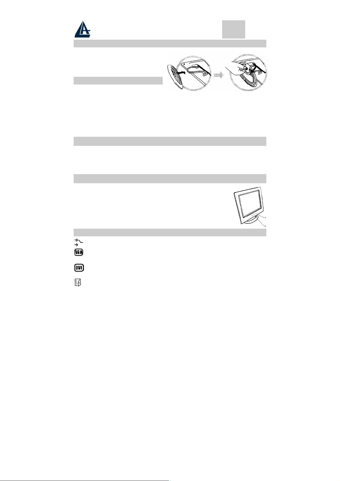
2.2 Installing the Base
Follow these steps to install the base:
1. Turn the monitor down.
2. Assembly the base to the arm with screw.
3. Tie the screw with a coin.
2.3 Installing the Monitor
This monitor is equipped with an auto sensing DC power adapter for voltage ranges 100-240VAC, 60/50Hz.
Confirm the line voltage designation on the rear panel of the monitor. Follow these steps to install the
monitor:
1. Before you connect the cables, made sure that the monitor and the system uni power switches
are off.
2. Plug one end of the 15pin-signal cable to the monitor and the other end to the video signal
A05-17AM-D01 - A05-17BM-D03 - A05-19BM-D02_X02 6 - 40
connector at the rear of the system. Tighten the two screws on the cable connector.
Page 7

ENGLISH
3. Connect the DC power cord to the DC jack.
4. Connect the power cable.
3 Control Functions
The monitor digital control functions are located on the front panel. They are shown in the figure below
and described in the following paragraphs.
1. Power Switch with Indicator LED
2. Function Keys
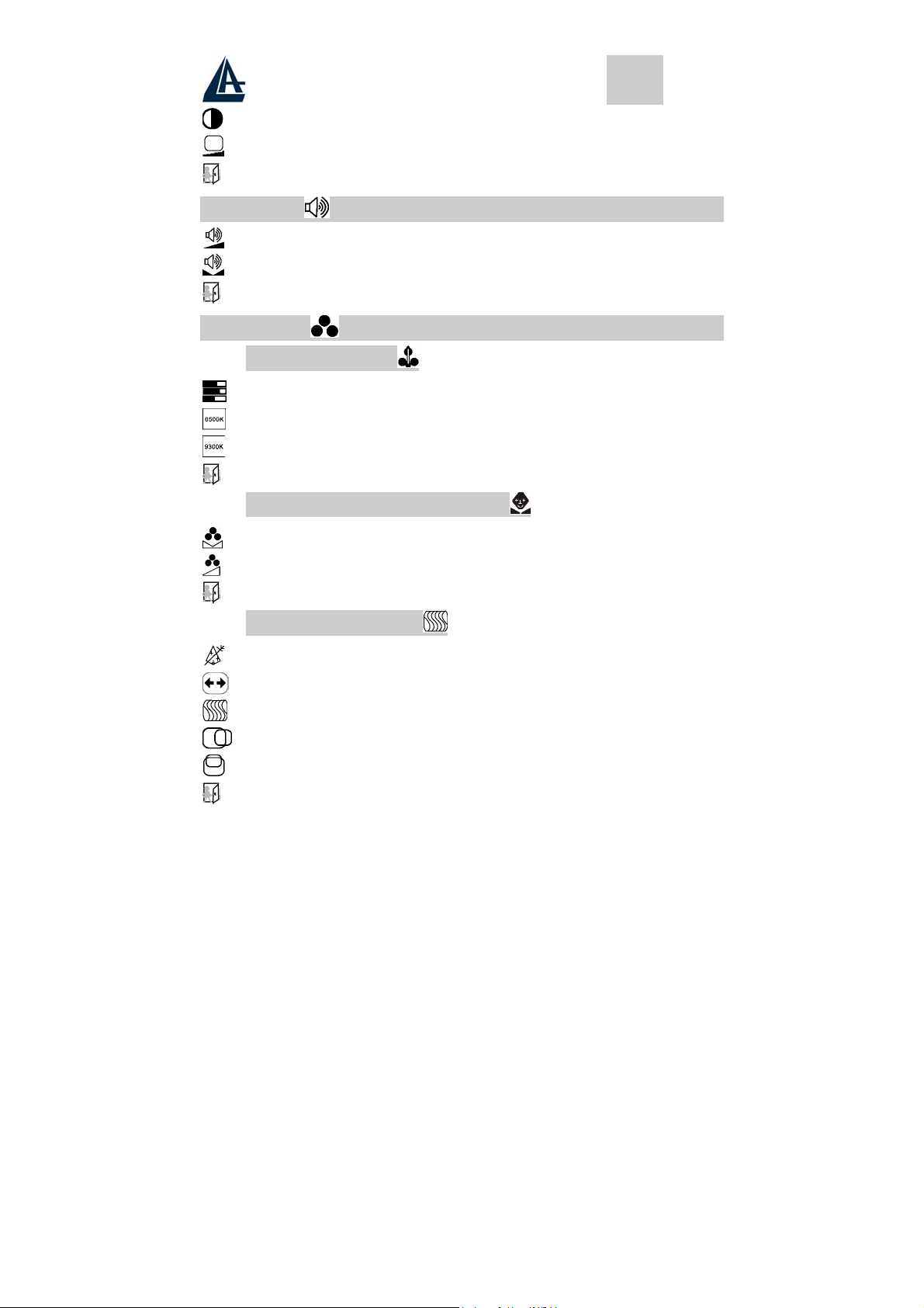
4 Function Select
With the U and V knobs, you can adjust the speakers volume.
Press the 1 knob to show the OSD menu. Than use the U and V knobs to select
a function. Press the 2 knob to close the OSD menu. You can hold the 2 knob for
more than 3 second to adjust the image quality automatically.
4.1 Input Select (not for A05-17AM-D01)
Input Select
VGA signal Select the image signal coming from the VGA cable.
DVI signal Select the image signal coming from DVI cable. (option)
Exit Close the Signal Select OSD menu.
4.2 Video
Brightness Adjust the luminance level in the image.
Contrast Adjust the difference in luminance between light and dark areas of the
Black Level Adjust the black Level in the image.
Exit Close the Video OSD menu.
image.
4.3 Audio
Volume Adjust the volume of speakers
Balance Adjust the speaker’s volume to right side or left side.
Exit Close the Audio OSD menu
A05-17AM-D01 - A05-17BM-D03 - A05-19BM-D02_X02 7 - 40
Page 8

ENGLISH
4.4 Color
4.4.1 Color Temperature
User Adjust the R.G.B. gain level.
6500K Select color temperature to 6500°K.
9300K Select color temperature to 9300°K.
Exit Close the Color Temperature OSD menu.
4.4.2 Adjust the flesh tone of the image
Shade Adjust the shade of the image color.
Saturation Adjust the saturation of the image color.
Exit Close the Color OSD menu.
4.4.3 Image Adjust
Geometry Adjust geometry of the image automatically.
Horizontal size Adjust the horizontal sync size of signal.
Horizontal phase Adjust the horizontal sync phase of signal.
Horizontal position Adjust the horizontal position of the image.
Vertical position Adjust the vertical position of the image.
Exit Close the Image OSD menu
4.5 Language
Sets the language of the OSD windows.
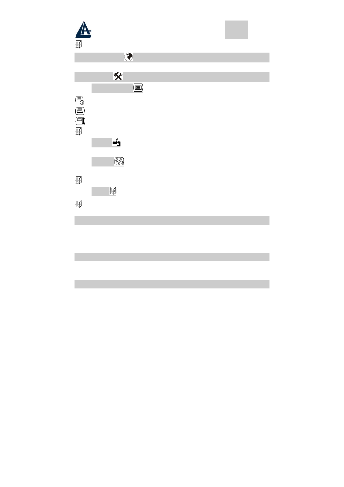
4.6 Tools
4.6.1 OSD Controls
Display time Setting the OSD menu display time.
OSD H. Position OSD H. Position Adjust the horizontal position of the OSD menu.
OSD V. Position OSD V. Position Adjust the vertical position of the OSD menu.
Exit Close the OSD Control OSD menu
A05-17AM-D01 - A05-17BM-D03 - A05-19BM-D02_X02 8 - 40
Page 9
ENGLISH
4.6.2 Recall the factory default setting
4.6.3 Sharpness
Adjust the picture display more clear
Exit Close the Tools OSD menu
Exit Close the OSD menu
5 Micro-controller Features
The micro-controller automatically detects the video board installed in your system. When you turn on the
monitor, the micro-controller first checks the display mode memory stored in the user setting area of the
video board, and then the factory presetting area. It then adjusts to the proper display mode.
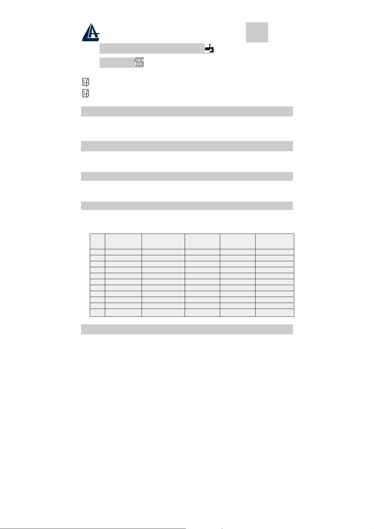
6 Display Modes Memory
The micro-controller has the memory capacity to store different display modes, including timing formats and
display-settings. This memory capacity is divided into two parts: the user setting area and the factory
presetting area.
6.1 User Setting Area
The user setting area on the micro-controller maintains in its memory the last display modes set by the
user. You can change the settings, or add a nonstandard mode. The micro-controller always detects and
displays the last mode stored in the user setting area first when the monitor is turned on.
6.2 Factory Presetting Area
There are some preferred display modes preset in the micro-controller. These display modes are preset
at the factory and include the most popular display modes currently available. The micro-controller
searches for a proper display mode in this area if it fails to find a proper display mode in the user setting
area.
1. VGA 640×350 31.5 70 Non-interlaced
2. VGA 720×400 31.5 70 Non-interlaced
3. VGA 640×480 31.5 60 Non-interlaced
4. VESA/75 640×480 37.5 75 Non-interlaced
5. VESA/60 800×600 37.9 60 Non-interlaced
6. VESA/75 800×600 46.9 75 Non-interlaced
7. VESA/60 1024×768 48.4 60 Non-interlaced
8. VESA/70 1024×768 56.5 70 Non-interlaced
9. VESA/75 1024×768 60.0 75 Non-interlaced
10. VESA/60 1280×1024 64.0 60 Non-interlaced
11. VESA/75 1280×1024 80.0 75 Non-interlaced
MODE
Resolution
(Dots*lines)
Horizontal
Freq. (KHz)
Vertical
Freq. (Hz)
Remark
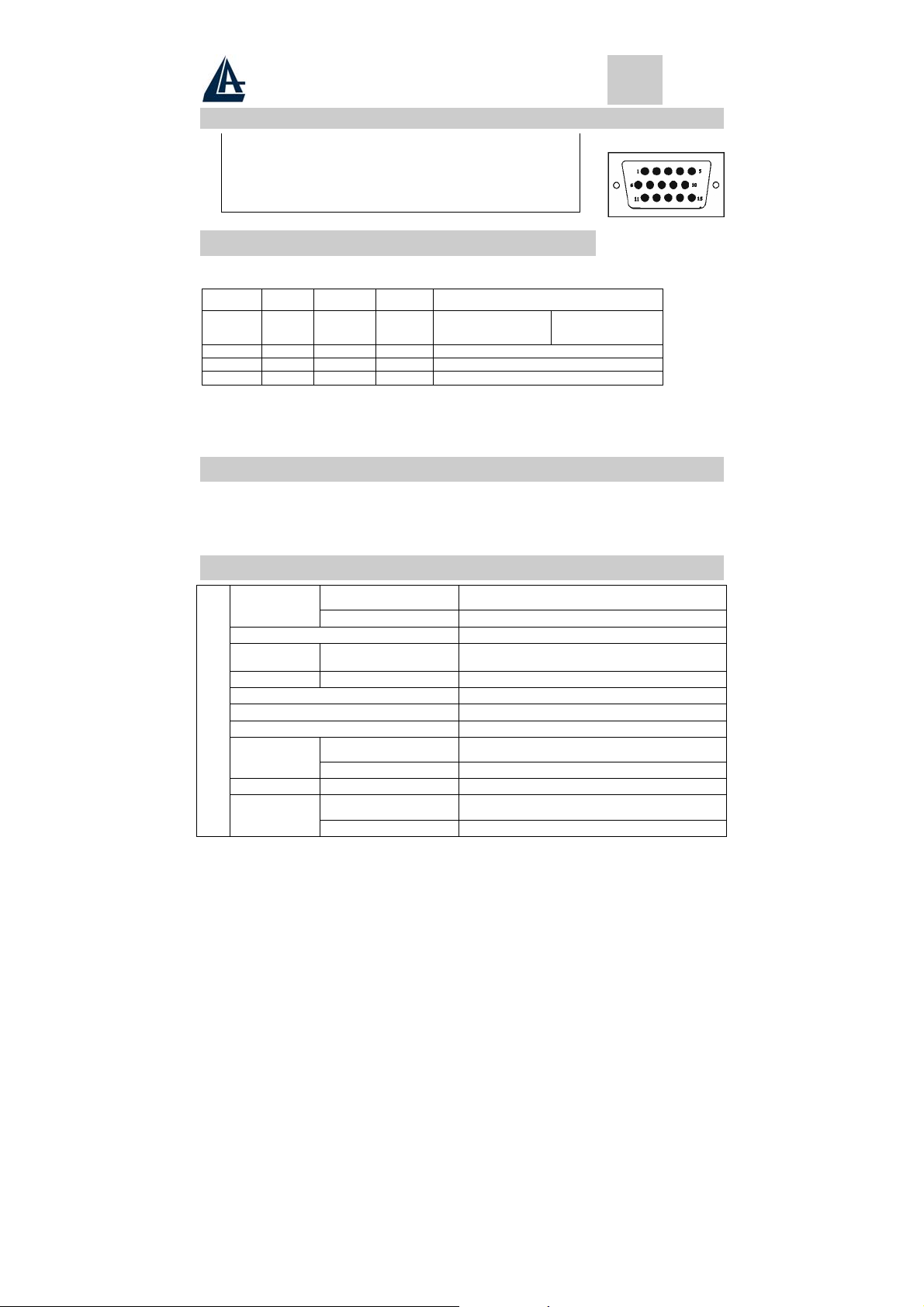
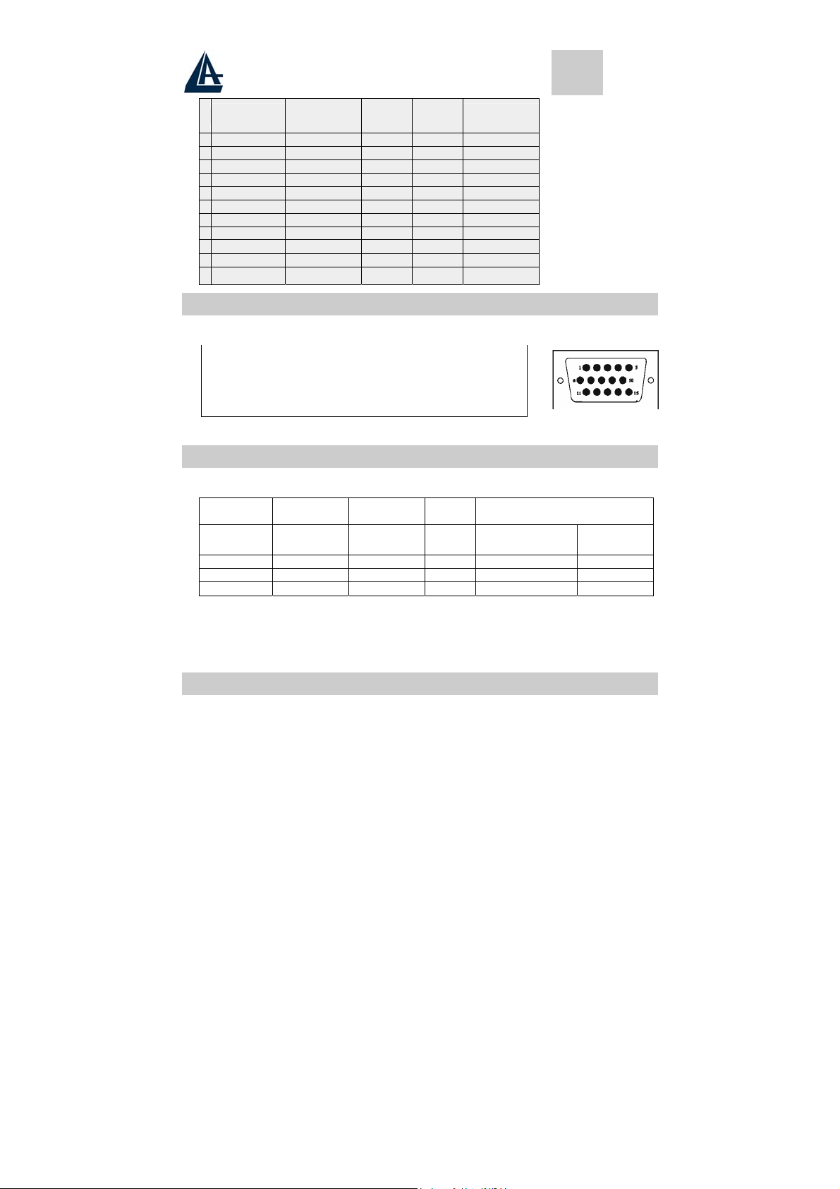
7 Signal Connector Pin-outs
To connect VGA, 8514A or IBM-compatible graphics adapters, use a 15 pin mini D-type male connector.
A05-17AM-D01 - A05-17BM-D03 - A05-19BM-D02_X02 9 - 40
Page 10
ENGLISH
7.1 15-pin Mini D-type Male VGA Connector
1 Red Video 6 Red Ground 11 Ground
2 Green Video 7 Green Ground 12 Serial Data/I/O
3 Blue Video 8 Blue Ground 13 H. Sync
4 Ground 9 No Connection 14 V. Sync
No Connection
5
Sync Ground
10
Serial Clock Input
15
8 Power Saving Feature
When the power saving active them the power indicator LED will be from Green Light to Amber, And
power saving feature complies with these VESA power saving modes:
Mode H. Sync. V. Sync. LED
Normal On On Green
Stand-by Off On Amber < 3W
Suspend On Off A m b e r < 3W
Off Off Off Ambe r < 3W
The monitor uses the H. Sync and V. Sync signals to determine the operation mode to enter.
The monitor power-saving feature automatically turns off H. Sync and V. Sync if there is no input from the
system for a certain period of time. To use this feature, you need a green PC that is compliant with the
VESA power saving feature or a software utility to detect system input such as keyboard or mouse.
<40W
Power Consumption
A05-17AM-D01
A05-17BM.D03
<45W
A05-19BM-D02
9 Time Settings
Time settings are adjusted from the system unit by software. To fulfill the requirements in the NUTEK
specification 803299/94 the total time from indicated inactivity to Power Saving position A2 (VESA OFF)
must not be set more than 70 minutes. We recommend you switch off the monitor when you do not intend to
use it for awhile.
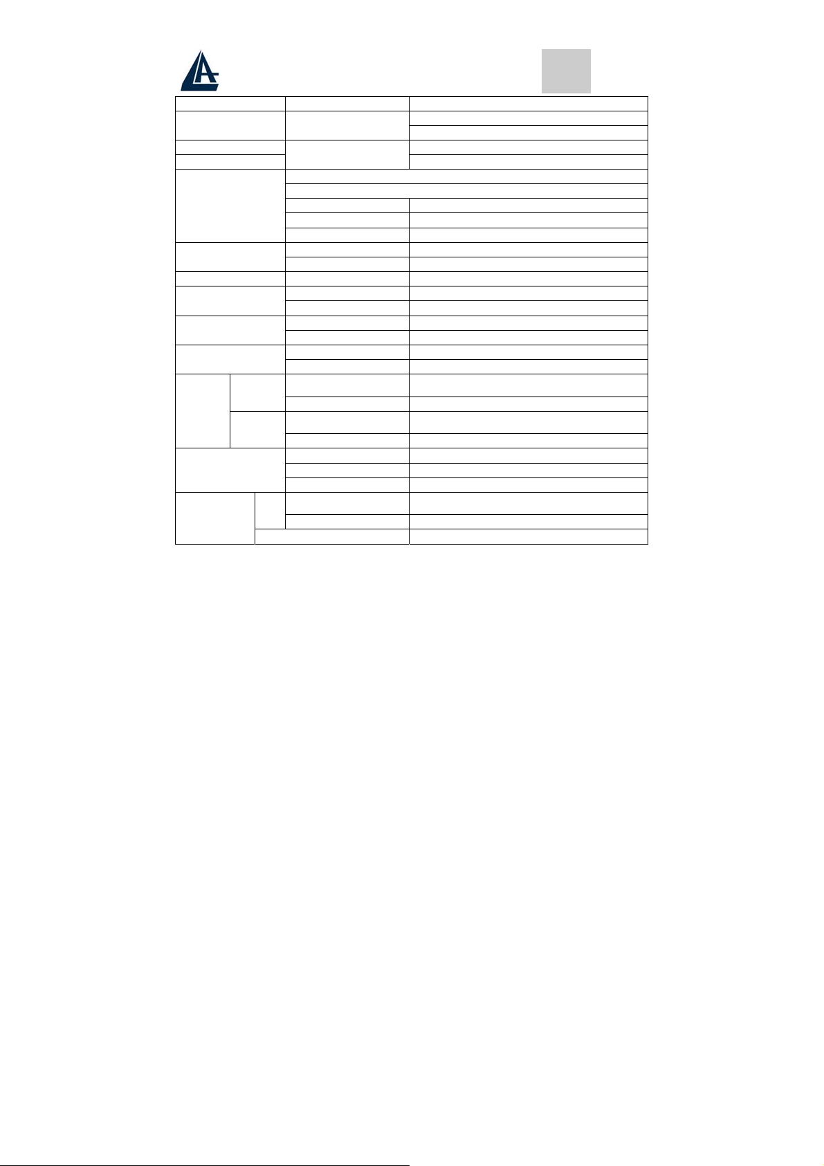
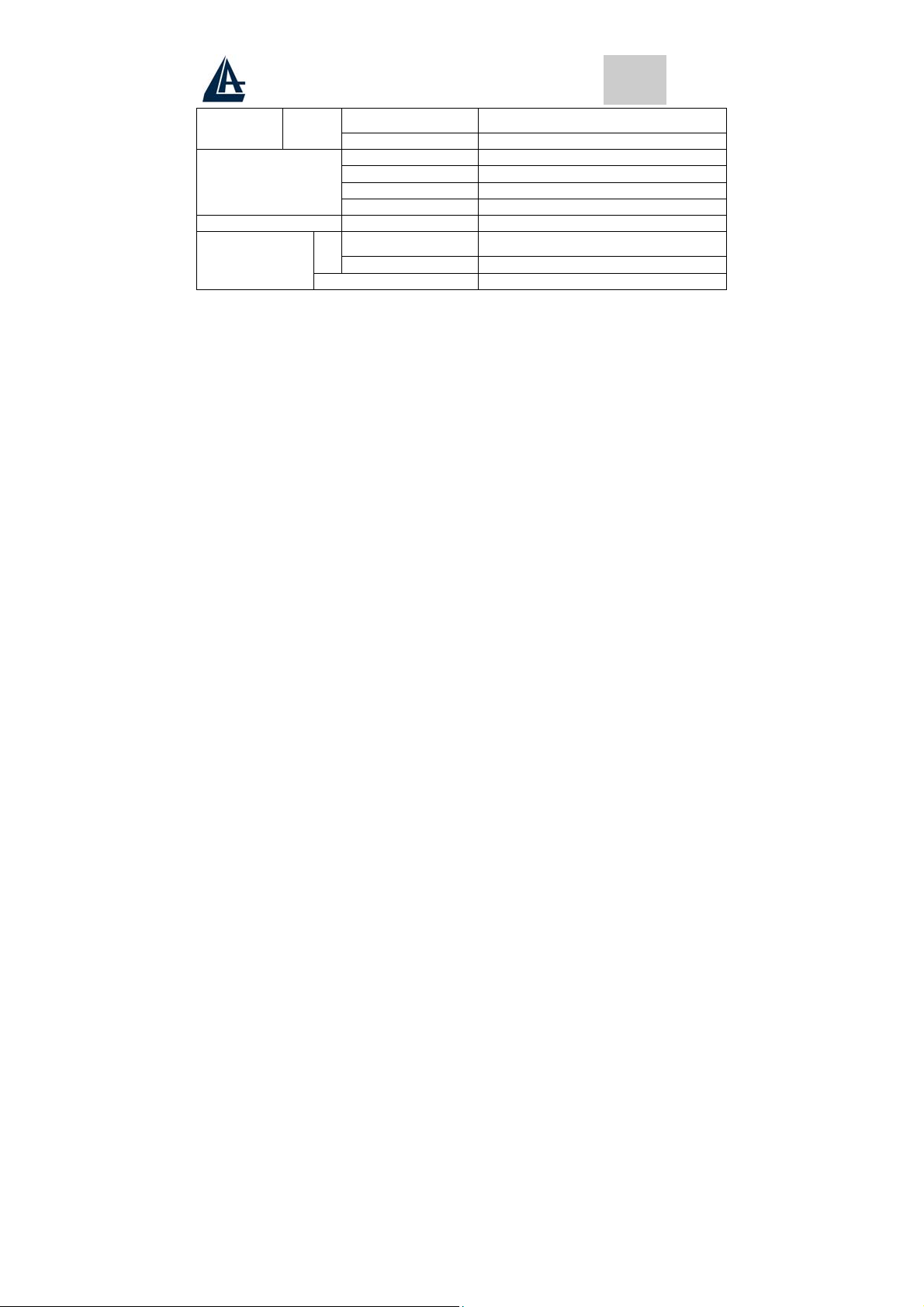
10 Specifications
A05-17AM-D01
Size
Type TFT (Thin Film Transistor), Active Matrix Panel
Pixel Pitch
Color 16.7M
LCD
Glass surface Anti-Glare & Hard Coat 3H
Brightness 250 cd/m2
Contrast
View Angle 170 H - 170 V
Full screen
A05-17AM-D01 - A05-17BM-D03 - A05-19BM-D02_X02 10 - 40
A05-17BM.D03
A05-19BM-D02
A05-17AM-D01
A05-17BM.D03
A05-19BM-D02
A05-17AM-D01
A05-17BM.D03
A05-19BM-D02
A05-17AM-D01
A05-17BM.D03
A05-19BM-D02
17.0" (full 17.0" viewable diagonal area)
19.0" (full 17.0" viewable diagonal area)
0,264mm
0,294mm
500:1
600:1
337.92x270.336 mm
376.320X301.056 mm
Page 11
ENGLISH
Resolution Primary Mode 1280x1024 @75Hz (Max.)
Input Signal Video
Connectors D-sub 15 pin
Input Signal
RGB Analog
DVI Digital (not for A05-17AM-D03)
DVI-D (not for A05-17AM-D03)
Sync H. V., Separate Sync,
TTL Compatible
Video Sync
Horizontal Frequency 31-80kHz,
Vertical Frequency 50-75Hz,
Video Bandwidth 80MHz
Audio
Input Stereo mini- Audio Line-in
Speakers 3W x 2 (At 1KHz for THD 1% Amplifier)
Power Voltage 220V - 12V / 4.2A
Operating
Conditions
Temperature 0°C to 40°C
Humidity 10-90% (non-condensing)
Temperature 0 to 60 Storage
Conditions
Dimensions
Net
Weight
Gross
Humidity 10-90% (non-condensing)
Physical 425mm (L) x 175mm (W) x 425mm (H)
Package 490mm (L) x 155mm (W) x 500mm (H)mm
A05-17AM-D01
A05-17BM.D03
A05-19BM-D02
A05-17AM-D01
A05-17BM.D03
A05-19BM-D02
5.5 Kg
6,0 Kg
7.0 Kg
7,5 Kg
Safety UL/CUL, TUV/GS, CE, CB, FCC-B
Regulations
Energy Star EPA
Quality ISO 13404-2 Class II
Power saving
On
A05-17AM-D01
A05-17BM.D03
A05-19BM-D02
<42W
<45W
Off <3W
A05-17AM-D01 - A05-17BM-D03 - A05-19BM-D02_X02 11 - 40
Page 12

Page 13

ITALIANO
Avvertenze
• Leggere attentamente queste informazioni e tenerle disponibili per una eventuale consultazione
successiva.
• Tenere presente anche tutte le indicazioni riportate sul prodotto.
• Staccare ogni collegamento elettrico quando viene effettuata la pulizia. Non usare mai liquidi o un
detergente a spruzzo, usare sempre un panno leggermente umido.
• Consultare quanto riportato a pagina 14 Pulizia del pannello LCD, per ulteriori dettagli
• Mantenere sempre il monitor fuori da aree con alta percentuale di umidità.
• Mantenere il prodotto in posizione stabile. L’eventuale caduta potrebbe causare un
danneggiamento serio.
• Non chiudere le aperture presenti sul monitor, servono per la ventilazione. Non installare il monitor
in aree poco ventilate e mantenerlo sempre lontano da fonti di calore.
• Il cavo di alimentazione utilizzato deve essere quello fornito col prodotto. Chieda al suo rivenditore
in caso di eventuali dubbi.
• Il cavo è provvisto del filo di terra onde evitare scariche elettriche. Non utilizzare cavi di
alimentazione sprovvisti della connessione di terra.
• Non porre il cavo di alimentazione in luoghi di passaggio, e non mettere nulla di pesante sopra.
• Non inserire oggetti o versare liquidi tramite le aperture. Sono presenti all’interno aree di alta
tensione che potrebbero causare scosse elettriche o corto circuiti.
• Non cercare di riparare da solo il monitor.
• Contattare il nostro centro di assistenza.
• Non toccare il cavo di alimentazione nelle situazioni qui indicate, ma chiamare un elettricista
esperto:
• Quando il cavo di alimentazione è danneggiato o tagliato
• Se del liquido è stato versato nel monitor
• Se il prodotto è stato esposto alla pioggia o ad elevata umidità
• Se il prodotto non può essere tarato e settato tramite le normali procedure di installazione.
Eventuali tarature ulteriori devono essere effettuate da un centro specializzato.
• Se il monitor è stato aperto o rotto.
• Se si evidenziano rilevanti modifiche nel funzionamento.
• Utilizzare il cavo di alimentazione a corredo per un utilizzo sicuro e per evitare incidenti.
11 Prima di iniziare
Congratulazioni per il Suo acquisto di questo monitor LCD. Legga attentamente questa sezione del
manuale per una rapida conoscenza del prodotto e delle operazioni da effettuare correttamente.
IMPORTANTE: CONSERVI LA SCATOLA DELL’IMBALLO E TUTTO IL MATERIALE
’IMBALLO, POTREBBE SERVIRE PER EVENTUALI FUTURE SPEDIZIONI.
DELL
11.1 Precauzioni
• Tenersi ad almeno 45 cm di distanza dal pannello durante l’uso.
• Non fare pressioni sul pannello: è fragile
• Non toccare il pannello con le mani sporche. L’unto della pelle risulta di difficile rimozione.
• Non esporre direttamente il pannello alla luce solare o ad altre fonti di calore.
• Durante l’utilizzo, non indirizzare luci dirette sul pannello, per evitare fastidiosi riflessi.
• È importante scegliere un posto ben ventilato dove posizionare il monitor. Non porre nulla sopra il
monitor.
• In presenza di fumo, rumori strani, o odori particolari, spegnere immediatamente il monitor e
chiamare il centro assistenza. Non continuare comunque ad utilizzare il monitor.
A05-17AM-D01 - A05-17BM-D03 – A05-19BM-D02_X02
Page 14

ITALIANO
• Non rimuovere il guscio posteriore. Il monitor contiene un’area ad alta tensione e si corre il rischio
di ricevere una forte scarica elettrica. Contattare il centro di assistenza per ogni necessità.
• Se è necessario muovere il monitor, usare sempre attenzione.
• Non fare pressioni sul pannello LCD in caso di malfunzionamenti. Fare riferimento alla pagina 15
per eventuali tarature.
11.2 Pulizia del pannello LCD
• Utilizzare un pennello in pelo di cammello per lenti o un panno soffice, pulito e non peloso, per
togliere dal pannello tracce di polvere e di ogni altra impurità; strofinare leggermente per non rigare
il pannello.
• Se qualche impurità permane, inumidire leggermente il panno ripetere l’operazione.
• Non versare mai e neppure spruzzare liquidi sul pannello.
NON PREMERE MAI SUL PANNELLO.
11.3 Comunicato relativo alle interferenze Radio
Questa apparecchiatura è stata esaminata e giudicata conforme ai limiti per le apparecchiature digitali della
Classe B, rispettando la parte 15 delle Regole FCC.
Questi limiti sono stati definiti per provvedere ragionevoli protezioni contro le interferenze in installazioni di
tipo residenziale. Questa apparecchiatura genera, usa e può irradiare onde elettromagnetiche, se non è
installato ed utilizzato in accordo con le istruzioni, può causare interferenze percepibili alle comunicazioni
radio. Comunque non esiste garanzia che nessuna interferenza possa mai accadere in installazioni
particolari.
Se questa apparecchiatura dovesse creare interferenze a radio o televisori, durante la fase di accensione o
spegnimento, l’utente è invitato a correggere le interferenze tramite una delle seguenti modalità:
• Riorientare o riposizionare l’antenna ricevente
• Aumentare la distanza tra questa apparecchiatura ed il ricevitore
• Alimentare l’apparecchiatura da una presa diversa rispetto a quella alla quale sia collegata il
ricevitore.
• Consultare il rivenditore o un esperto tecnico radio/TV per un aiuto.
11.3.1 FCC Avvertimento
Per assicurare la continuità del rispetto delle normative FCC, l’utilizzatore deve assicurare un corretto
collegamento di terra al cavo di alimentazione, assicurarsi che il cavo di collegamento video sia schermato
con una opportuna maglia di ferrite.
Inoltre, ogni cambio o modifica non autorizzata di questo monitor LCD potrebbero invalidare il diritto
dell’utente di utilizzare questa apparecchiatura.
11.4 Precauzioni per il cavo di alimentazione
Utilizzare un cavo fornito di corretto collegamento a terra.
12 Installazione del monitor
12.1 Disimballo
Aprire la confezione e controllarne il contenuto.
Se vi sono componenti mancanti o danneggiati, rivolgersi immediatamente il rivenditore.
La confezione deve includere i seguenti elementi:
• Monitor a colori TFT
• Guida dell'utente
• Cavo di alimentazione
• Cavo del segnale
• Alimentatore CC
A05-17AM-D01 - A05-17BM-D03 – A05-19BM-D02_X02
Page 15

ITALIANO
• Cavo Audio
12.2 Installare la base
Segua questi passi per installare la base:
3. Capovolgere il monitor.
4. Fissare la base al braccio con la vite.
5. Stringere la vite con una moneta.
12.3 Installazione del
monitor
Questo monitor è dotato di un alimentatore DC che
funziona con una tensione che deve essere compresa tra 100-240VAC 60/50Hz. Verificare la tensione
indicata sul pannello posteriore del monitor. Per installare il monitor eseguire le operazioni seguenti:
1. Prima di collegare i cavi, assicurarsi che gli interruttori dell’alimentazione del monitor e del
personal computer siano spenti.
2. Inserire un connettore del cavo del segnale a 15 pin nel monitor e l’altra estremità alla
scheda video sul retro del sistema. Stringere le due viti sul connettore.
3. Connettere il cavo di alimentazione DC al jack DC.
4. Connettere il cavo di alimentazione.
13 Funzioni di Controllo
Le funzioni di controllo digitali del monitor si trovano sul pannello anteriore. Sono indicate
nella figura riportata sotto e descritte nei paragrafi che seguono.
14 Selezione della funzione
Premere il tasto 1 per visualizzare il menu OSD, quindi usare i tasti e per
selezionare una funzione.
Con i tasti e , è possibile regolare il volume degli altoparlanti. Premere il tasto
2 per chiudere il menu OSD
Per regolare automaticamente la qualità dell’immagine tenere premuto per un
periodo superiore a 3 secondi il tasto 2.
Il menu OSD viene chiuso automaticamente dopo 3-5 secondi di inattività
salvando le eventuali modifiche effettuate.
14.1 Selezione ingresso (non per A05-17AM-D01)
Selezione ingresso
Segnale VGA Seleziona l’ingresso video dal connettore VGA.
Segnale DVI Seleziona l’ingresso video dal connettore DVI.(Non
Uscita Termina la funzione selezione ingresso.
disponibile nel modello A05-17AM-D01)
14.2 Video
Luminosità Regola la luminosità dell’immagine
A05-17AM-D01 - A05-17BM-D03 – A05-19BM-D02_X02
Page 16
ITALIANO
Contrasto Regola la differenza tra le aree luminose e quelle scure dell’immagine
Livello del nero Regola il livello del nero.
Exit Per terminare le regolazioni dello schermo
14.3 Audio
Volume Regola il volume degli altoparlanti
Bilanciamento Regola il bilianciamento del segnale tra destra e sinistra
Exit Per terminare le regolazioni audio
14.4 Colore
14.4.1 Temperatura Colore
User Regola i livelli di Rosso, Blu e Verde
6500K Posiziona la temperatura colore a 6500°K.
9300K Posiziona la temperatura colore a 9300°K.
Exit Per terminare le regolazioni della temperatura Colore
14.4.2 Regolazione del tono dell’immagine
Sfumatura Regola le sfumature del colore
Saturazione Regola la saturazione dei colori
Exit Termina la regolazione del tono
14.4.3 Regolazione Immagine
Geometria Regola automaticamente la geometria dell’immagine.
Grandezza Regola la grandezza orizzontale dell’immagine
Fase Regola la fase
Posizione orizzontale Regola la posizione orizzontale dell’immagine
Posizione verticale Regola la posizione Verticale dell’immagine
Exit Close the Image OSD menu
A05-17AM-D01 - A05-17BM-D03 – A05-19BM-D02_X02
Page 17

ITALIANO
14.5 Lingua
Seleziona la lingua del menu.
14.6 Strumenti vari
14.6.1 Controlli OSD
Temporizzazione Regola il tempo di visualizzazione dell’OSD
Pos. Orizzontale Controlla il posizionamento orizzontale dell’OSD
Pos. Verticale Controlla il posizionamento verticale dell’OSD
Exit Chiude la regolazione dell’OSD
14.6.2 Richiama le regolazioni di fabbrica
14.6.3 Regolazione fine
Permette una regolazione più raffinata dell’immagine
Exit Chiude la funzione strumenti
Exit Chiude la finestra OSD
15 Caratteristiche Microprocessore
Il Microprocessore riconosce automaticamente la scheda video installata nel sistema. Quando si
accende il monitor, il microprocessore per prima cosa controlla il tipo di monitor memorizzato nelle
impostazioni dell’utente della scheda video, quindi le impostazioni di fabbrica. Infine viene regolata
l’impostazione corretta.
16 Memoria Modalità Schermo
Il Microprocessore memorizza diverse modalità di visualizzazione, oltre al formato di sincronizzazione e
alle impostazioni dello schermo. Questa memoria è divisa in due aree: l’area delle impostazioni
dell’utente e l’area delle impostazioni di fabbrica.
16.1 Area Impostazioni dell’Utente
L’area delle impostazioni dell’utente sul Microprocessore mantiene in memoria le ultime modalità di
schermo impostate dall’utente.
Il Microprocessore riconosce e visualizza sempre l’ultima modalità memorizzata nell’area delle
impostazioni dell’utente quando il monitor viene acceso.
16.2 Area Impostazioni di Fabbrica
Sono presenti sul Microprocessore alcune modalità di schermo più frequentemente utilizzate. Queste
modalità di schermo sono già impostate dalla fabbrica e includono le più comuni modalità attualmente
disponibili. Il Microprocessore cerca la modalità più corretta in questa area, qualora non sia stata trovata
una modalità accettabile nell’area delle impostazioni dell’utente.
A05-17AM-D01 - A05-17BM-D03 – A05-19BM-D02_X02
È possibile cambiare le impostazioni o aggiungere una nuova modalità.
Page 18
ITALIANO
Modalità
1 VGA 640x350 31.5 70 Non interlacc.
2 VGA 720x400 31.5 70 Non interlacc.
3 VGA 640x480 31.5 60 Non interlacc.
4 VESA/75 640x480 37.5 75 Non interlacc.
5 VESA/60 800x600 37.9 60 Non interlacc.
6 VESA/75 800x600 46.9 75 Non interlacc.
7 VESA/60 1024x768 48.4 60 Non interlacc.
8 VESA/70 1024x768 56.5 70 Non interlacc.
9 VESA/75 1024x768 60.0 75 Non interlacc.
10 VESA/60 1280x1024 64.0 60 Non interlacc.
11 VESA/75 1280x1024 80.0 75 Non interlacc.
Risoluz.
(punti x linee)
Freq.Orizz.
(KHz)
Freq.Vert.
(Hz)
Note
17 Piedinatura del cavo segnale VGA
Per collegare adattatori grafici VGA, 8514A o IBM compatibili, utilizzate un mini cavo maschio di tipo D a
15 pin.
1 Video Rosso 6 Rosso Terra 11 Terra
2 Video Verde 7 Verde Terra
3 Video Blu 8 Blu Terra 13 Sincro Orizz.
4 Terra 9 Non utilizzato 14 Sincro Vert.
5 Non utilizzato 10 Sync Terra 15 Ingresso Clock
12 Data/I/O
18 Funzioni per il risparmio energetico
Quando si attiva la funzione di risparmio energetico, l’indicatore LED di alimentazione passerà da verde
a rosso. La funzione di risparmio energetico si configura secondo le seguenti modalità VESA:
Modalità
Normale Acceso Acceso Verde < 40 W A05-17AM-D01
Stand-by Spento Acceso Rosso < 3 W < 3 W
Sospeso Acceso Spento Rosso < 3 W < 3 W
Spento Spento Spento Rosso < 3 W < 3 W
Il monitor utilizza i segnali di sincronizzazione orizzontale e verticale per decidere in quale modalità entrare.
La funzione di risparmio energetico del monitor spegne automaticamente la sincronizzazione orizzontale e
verticale se non vi è alcun segnale proveniente dal computer per un periodo. Per utilizzare questa funzione,
vi serve un PC verde omologato alle funzioni di risparmio energetico VESA o un programma per rilevare
segnali provenienti dal computer, per esempio dalla tastiera o dal mouse.
Sincroniz.
Orizz.
Sincroniz.
Vert.
LED
Consumo energetico
A05-17BM.D03
< 45 W
A05-19BM-D02
19 Regolazione del tempo
La regolazione del tempo viene operata dal programma che sta girando nel computer. Per soddisfare i
requisiti menzionati nel NUTEK 803299/94, il tempo totale di inattività prima di entrare nella funzione di
risparmio energetico A2(VESA spento) non deve essere regolato a più di 70 minuti. Vi raccomandiamo
di spegnere il monitor quando avete intenzione di non utilizzarlo per un po’ di tempo.
A05-17AM-D01 - A05-17BM-D03 – A05-19BM-D02_X02
Page 19

ITALIANO
20 Specifiche
A05-17AM-D01
Dimensioni
A05-17BM.D03
A05-19BM-D02
Tipo TFT (Thin Film Transistor), Active Matrix Panel
A05-17AM-D01
Pixel Pitch
A05-17BM.D03
A05-19BM-D02
Colori 16.7M
LCD
Trattamento superficie Anti-Glare & Hard Coat 3H
Luminosità 250 cd/m2
A05-17AM-D01
Contrasto
A05-17BM.D03
A05-19BM-D02
Angolo Visuale 170 H - 170 V
A05-17AM-D01
Area Visibile
A05-17BM.D03
A05-19BM-D02
Risoluzione Primaria 1280x1024 @75Hz (Max.)
Segnale ingresso Video
Sync H. V., Separate Sync,
TTL Compatibile
Video Sync
Frequenza Orizzontale 31-80kHz,
Frequenza Verticale 50-75Hz,
Banda Passante 80MHz
Connettore Input Signal
Audio
Input Stereo mini- Audio Line-in
Altoparlanti 3W x 2 (At 1KHz for THD 1% Amplifier)
Alimentazione 220 V 12V / 4.2A
Condizioni di utilizzo
Condizioni di imballo
Dimensioni
Netto:
Peso
Lordo:
Temperatura 0°C to 40°C
Umidità 10-90% (senza condensa)
Temperatura 0 a 60
Umidità 10-90% (senza condensa)
Prodotto 425mm (L) x 175mm (W) x 425mm (H)
Imballo 490mm (L) x 155mm (W) x 500mm (H)mm
A05-17AM-D01
A05-17BM.D03
A05-19BM-D02
A05-17AM-D01
A05-17BM.D03
A05-19BM-D02
Sicurezza UL/CUL, TUV/GS, CE, CB, FCC-B
Normative
Energy Star EPA
Qualità ISO 13404-2 Class II
17.0" (full 17.0" viewable diagonal area)
19.0" (full 17.0" viewable diagonal area)
0,264mm
0,294mm
500:1
600:1
337.92x270.336
376.320X301.056 mm
RGB Analogico
DVI Digitale (non per A05-17AM-D01)
D-sub 15 pin
DVI-D (non per A05-17AM-D01)
5.5Kgs
6,0 Kg
7.0Kg
7,5 Kg
A05-17AM-D01 - A05-17BM-D03 – A05-19BM-D02_X02
Page 20

ITALIANO
Risparmio
Energetico
A05-17AM-D01
On
A05-17BM.D03
A05-19BM-D02
Off <3W
<42W
<45W
A05-17AM-D01 - A05-17BM-D03 – A05-19BM-D02_X02
Page 21

FRANCAIS
Instructions
• Lire ces renseignements attentivement et les conserver pour une consultation ultérieure.
• Conserver aussi toutes les indications se reportant au produit.
• Déconnecter chaque liaison électrique avant d’effectuer le nettoyage de l’écran. Ne jamais pas
utiliser de liquides ou de détergent, utiliser toujours un tissu légèrement humide.
• Consulter tout ce qu'a été reporté à la page 22 Nettoyage du panneau LCD, pour de plus ample
informations.
• Maintenir toujours l'écran à l’abri de zones ayant un fort pourcentage d'humidité.
• Maintenir le produit en position stable. La chute éventuelle de l’écran pourrait causer un dommage
sérieux.
• Ne pas obstruer les ouvertures présentes sur l'écran elles sont utiles pour la ventilation. Ne pas
installer l'écran en zones confinée et le maintenir toujours loin des sources de chaleur.
• Le câble d'alimentation utilisé doit être celui fourni avec le produit. Demander à votre détaillant en
cas de doutes éventuels.
• Le câble possède un du fil de terre afin d'éviter les décharges électrostatiques. Ne pas utiliser de
câbles d'alimentation dépourvue d’un fil de terre.
• Ne pas mettre le câble d'alimentation dans un endroit de passage, et ne pas le recouvrir d’objets
lourds.
• Ne pas insérer d'objets ou verser de liquides dans les ouvertures. Présence à l'intérieur de zones
de haute tension qui pourraient causer des cours circuits ou une électrocution.
• Ne pas essayer de réparer l'écran tout seul.
• Contacter notre centre d'assistance.
• Ne pas toucher le câble d'alimentation dans les situations indiquées ci-dessous, mais appeler un
technicien:
• Quand le câble d'alimentation est endommagé ou coupé
• Si du liquide a été versé dans l'écran
• Si le produit a été exposé à la pluie ou à une forte humidité
• Si le produit ne peut pas être réglé par les procédures normales d'installation. Les autres
réglages éventuels doivent être effectués par un centre spécialisé.
• Si l'écran a été ouvert ou cassé.
• Si des modifications importantes dans le fonctionnement persiste.
• Utiliser le câble d'alimentation fourni pour une utilisation sûre et éviter les incidents.
21 Avant de commencer
Permettez nous vous féliciter pour l’acquisition de cet écran LCD. Nous vous demandons de lire
attentivement cette section du manuel pour une prise en main rapide du produit et des opérations à
effectuer.
IMPORTANT: CONSERVER L'EMBALLE AU COMPLET, IL SERVIRA POUR UN ÉVENTUELS
RETOUR/ ECHANGE.
21.1 Précautions
• Se tenir à une distance d’au moins 45 cm de l’écran lors de l'utilisation.
• Ne pas faire de pression sur le panneau: risque de destruction (fragile).
• Ne pas toucher le panneau avec des mains sales. (risque de détérioration du filtre)
• Ne pas exposer le panneau directement à la lumière solaire ou à toutes autres sources de chaleur.
• Pendant l’utilisation, ne pas positionner l’écran face a une lumière directe, pour éviter les reflets.
• Il est important de choisir une place adaptée et aérée où positionner l'écran.
• Ne pas rien mettre sur l'écran.
• En présence de fumée, bruits étranges, éteindre l'écran immédiatement et appeler le centre
d’assistance. Ne pas continuer à utiliser l'écran.
A05-17AM-D01 - A05-17BM-D03 – A05-19BM-D02_X02
Page 22

FRANCAIS
• Ne pas enlever le panneau arrière. L'écran contient une zone de haute tension, risque
d’électrocution. Contacter le centre d'assistance en cas de nécessité.
• Tout déplacement de l’écran doit être fait avec la plus grande précaution.
• Ne pas faire de pression sur le panneau LCD même en cas de mauvais fonctionnements. Se
reporter à la page 23 pour procéder aux réglages éventuels.
21.2 Propreté du panneau LCD
• Utiliser un pinceau en poil de chameau pour verres ou un tissu moelleux, propre et non feutré,
pour enlever du panneau toutes traces de poussière et toutes autres impuretés; frotter légèrement
pour ne pas rayer le panneau.
• Si quelques impuretés reste, humidifier le tissu légèrement et répéter l'opération.
• Ne pas jamais verser ou vaporiser de liquide sur le panneau.
• Ne pas jamais exercer de pression sur le panneau.
21.3 Communiqué relatif aux interférences Radio
Cet équipement a été testé et déclaré conforme aux standards concernant les appareillages digitaux de la
Classe B, en respectant le §15 des Règles FCC.
Ces limites ont été définies pour pourvoir garantir une protection raisonnable contre les interférences en
installations de type résidentiel. Cet équipement peut engendrer, des perturbations électromagnétiques, s'il
n'est pas installé et utilisé en accord avec les instructions. Il peut causer également des interférences
perceptibles aux communications radio. Nous ne pouvons garantir qu'aucune interférence ne puisse arriver
dans le cas d’installations spéciales.
Si cet équipement devait créer des interférences pour la radio ou la télévision, pendant la phase d'allumage
ou d’extinction, l'utilisateur est invité à corriger les interférences par une des modalités suivantes
• Réorienter ou repositionner l'antenne réceptrice
• Augmenter la distance entre cet appareillage et le récepteur
• Alimenter l'équipement d'une prise différente de celle à laquelle est relié la radio ou la télévision.
• Consulter le détaillant ou une technicien radio / TV pour une aide.
21.3.1 FCC Avertissement
Pour maintenir la continuité du respect des normes FCC, l'utilisateur doit s’assurer que son branchement
électrique possède une mise à la terre efficace et que le câble de liaison vidéo est blindé et utilise une
ferrite.
Aucune modification ne doit être apporté à cet écran. Dans le cas contraire l’organisme des normes pourrait
réfuter le droit de l'utilisateur d'utiliser cet équipement.
:
21.4 Précautions pour le câble d'alimentation
UTILISER UN CABLE D’ALIMENTATION AVEC PRISE DE TERRE.
22 Installer l’écran
22.1 Déballage
Ouvrir le carton d’emballage et vérifier le contenu.
Si un élément est manquant ou endommagé, contacter votre revendeur immédiatement. Le
package doit comprendre les éléments suivants
• Moniteur couleur TFT
• Guide de l’utilisateur
• Câble d’Alimentation
• Câble Vidéo ( Sub D 15)
• Adaptateur d’alimentation DC
• Câble Audio
A05-17AM-D01 - A05-17BM-D03 – A05-19BM-D02_X02
Page 23
FRANCAIS
22.2 Installer la Base
1. Eteindre le moniteur.
2. Assembler la base au bras et visser
la vis prévu à cet effet.
3. Visser avec une pièce de monnaie.
22.3 Installer le Moniteur
Le moniteur est équipé d’un adaptateur
d’alimentation DC avec auto détection pour une
tension comprise entre 100-240VAC, 60/50Hz.
Suivez les étapes ci-dessous pour installer le moniteur.
1. Avant de connecter le câble, vérifier que l’interrupteur du moniteur est éteint.
2. Brancher le câble signal Sub D 15 pins d’un côté au moniteur et de l’autre côté au connecteur
du signal vidéo à l’arrière du système. Visser les deux vis au connecteur du câble.
3. Connecter le câble d’alimentation DC au connecteur DC.
4. Connecter le câble d’alimentation
23 Fonctions de Contrôle
Les boutons de fonctions de contrôle digital du moniteur sont localisées sur le panneau
avant. Ils sont illustré par le dessin ci-dessous et décrits dans les paragraphes suivants
1. Interrupteur d’Alimentation
2. Touches de Fonctions
24 Sélection des Fonctions
Appuyer sur le bouton 1 pour afficher le menu OSD . Et utiliser les boutons U et
V pour sélectionner une fonction.
Avec les boutons U et V, vous pouvez modifier le volume du haut parleur. P
Appuyer sur le bouton 2 pour terminer le menu OSD.
Vous pouvez appuyer sur le bouton 2 pendant plus de 3 secondes pour modifier
la qualité de l’image automatiquement.
Le menu OSD sera fermé automatiquement après 3-10 secondes d'attente et
sauvegardera les modifications que vous avez faites.
24.1 Sélection du signal entrant (sauf pour le A05-17AM-D01)
Signal Select
Signal VGA Sélectionne le signal Vidéo entrant depuis le câble
VGA.
Signal DVI Sélectionne le signal Vidéo entrant depuis le câble DVI (non
valide pour le A05-17AM-D01).
Sortie Ferme le menu Signal Select OSD
A05-17AM-D01 - A05-17BM-D03 – A05-19BM-D02_X02
Page 24

FRANCAIS
24.2 Video
Luminosité Modifie le niveau de luminosité de l’image
Contraste Modifie la différence de luminosité entre les parties sombres et éclairées
Niveau noir Modifie le niveau de noir de l’image.
Sortie Ferme le menu Video OSD
de l’image.
24.3 Audio
Volume Modifie le volume du haut parleur
Balance Modifie le volume du haut parleur, gauche ou droite
Sortie Ferme le menu Audio OSD
24.4 Couleur
24.4.1 Température de Couleur
Couleur Utilisateur Personnalise les quantités de R (Rouge) G (Vert) et B (Bleu)
6500K Sélectionne la température de couleur à 6500°K.
9300K Sélectionne la température de couleur à 9300°K.
Sortie Ferme le menu Température de Couleur OSD
24.4.2 Tonalité du Flash - Modifier la tonalité Flash d’image
Teinte Modifie le degré d’ombre de couleur de l’image
Saturation Modifie la saturation de couleur de l’image
Sortie Ferme le menu Couleur OSD.
24.4.3 Image
Auto Régler Modifie la géométrie de l’image automatiquement
Largeur H. Modifie la taille horizontale de l’image
Phase H. Modifie la phase H. de l’image
Position H. Modifie la position horizontale de l’image
Position V. Modifie la position verticale de l’image
A05-17AM-D01 - A05-17BM-D03 – A05-19BM-D02_X02
Page 25
FRANCAIS
Sortie Ferme le menu Image OSD
24.5 Langage
Choisir la langue utilisée pour l’ OSD. ( affichage des réglages à l’écran)
24.6 Outils
24.6.1 Contrôle OSD
Temporisateur Modifie le temps de visualisation de l’OSD
Position H. Modifie la position horizontale de l’OSD
Position V. Modifie la position verticale de l’OSD
Sortie Ferme le menu de l’OSD
24.6.2 Rappel
Remettre les paramètres usine par défaut.
24.6.3 Acuité
Permet une réglage plus affinée de l'image
Sortie Ferme le menu Outils de l’OSD
24.6.4 Sortie
Sortie Ferme le menu de l’OSD
25 Fonctions réglage automatique
La fonction réglage automatique permet de détecter automatiquement la carte vidéo installée dans votre
système grâce à un microcontrôleur. Lorsque vous allumez le moniteur, le microcontrôleur vérifie d’abord
les modes d’affichage sauvegardés dans la partie “Réglage par l’Utilisateur” (user setting area) de la carte
vidéo, et ensuite ceux dans la partie “Réglage Pré configuré” (factory presetting area). Le réglage se fait
alors d’une manière automatique pour permettre un affichage correct.
25.1 Sauvegarde des modes d’affichage
Le microcontrôleur garde en mémoire les différents modes d’affichage possible, comprenant le fuseau
horaire et les paramètres pour l’affichage d’image. La mémoire est divisée en deux parties : Réglage par
l’Utilisateur (the user setting area) et Réglage Pré configuré (the factory presetting area).
25.2 Réglage par l’Utilisateur
Dans la partie “Réglage par l’Utilisateur”, le microcontrôleur garde en mémoire la dernière
modification de l’utilisateur sur le mode d’affichage. Vous pouvez changer les paramètres ou
ajouter un mode d’affichage non standard. Le microcontrôleur détecte et utilise toujours le
dernier mode d’affichage sauvegardé dans la mémoire en premier lieu lorsque vous allumez le
moniteur.
A05-17AM-D01 - A05-17BM-D03 – A05-19BM-D02_X02
Page 26

FRANCAIS
g
25.3 Réglage Pré-Configuré
Dans cette partie, nous avons définit quelques modes d’affichages préférentiels utilisable par
le microcontrôleur. Les modes d’affichages sont pré-configurés en usine, incluant les modes
d’affichages disponibles les plus utilisés actuellement. Le microcontrôleur ne cherchera un
mode d’affichage utilisable que dans cette partie
Mode
1 VGA 640x350 31.5 70 Non entrelacé.
2 VGA 720x400 31.5 70 Non entrelacé
3 VGA 640x480 31.5 60 Non entrelacé
4 VESA/75 640x480 37.5 75 Non entrelacé
5 VESA/60 800x600 37.9 60 Non entrelacé
6 VESA/75 800x600 46.9 75 Non entrelacé
7 VESA/60 1024x768 48.4 60 Non entrelacé
8 VESA/70 1024x768 56.5 70 Non entrelacé
9 VESA/75 1024x768 60.0 75 Non entrelacé
10 VESA/60 1280x1024 64.0 60 Non entrelacé
11 VESA/75 1280x1024 80.0 75 Non entrelacé
Résolution
( points*lignes )
Fréq.Horiz.
(KHz)
Fréq.Vert.
(Hz)
Remarque
26 Disposition des Broches du Connecteur de Signal
VGA
Pour connecter des adaptateurs VGA, 8514A ou compatibles IBM, utilisez un mini connecteur mâle de type
D à 15 broches. (Sub D 15)
1 Vidéo Rou
2 Vidéo Vert 7 Terre Vert 12 Données I/O série
3 Vidéo Bleu 8 Terre Bleu 13 Synchro Horiz
4 Terre 9 NC 14 Synchro Vert
5 NC 10 Terre Synchro 15 Entrée horloge série
e 6 Terre Rouge11Terre
27 Caractéristique d'Economie d'Energie
Lorsque l'Economiseur d'Energie est activé,le voyant lumineux du bouton d’allumage passera du vert à
l’ambre; cette caractéristique d'Economie d'Energie est conforme aux modes VESA suivants:
Mode
Normal Marche Marche Vert
Attente Arrêt Marche Ambre < 3 W < 3 W
Veille Marche Arrêt Ambre < 3 W < 3 W
Arrêt Arrêt Arrêt Ambre < 3 W < 3 W
Le moniteur utilise des signaux Synchro H. et Synchro V. pour déterminer le mode d'opération à entrer. La
caractéristique d'Economie d'Energie éteint automatiquement Synchro H. et Synchro V. s'il n'y a pas
d'entrée dans le système depuis un certain temps. Pour utiliser une telle caractéristique, vous devez
posséder un PC conforme à la norme d'Economie d'Energie VESA ou un utilitaire de logiciel pour détecter
l'entrée dans le système, comme un clavier ou une souris.
A05-17AM-D01 - A05-17BM-D03 – A05-19BM-D02_X02
Synchro. H. Synchro. V
Voyant
Consommation d'Energie
A05-17AM-D01
< 40 W
A05-17BM.D03
< 40 W
A05-19BM-D02
Page 27

FRANCAIS
28 Définitions du Temps
Les définitions du temps sont ajustées par le logiciel depuis l'unité du système. Pour répondre aux
exigences des spécifications NUTEK 803299/94, le temps total d'inactivité indiquée en position A2 de
l'Economiseur d'Energie ( VESA ARRET ) ne doit pas être défini sur plus de 70 minutes. Nous vous
conseillons d'éteindre le moniteur lorsque vous ne voulez plus l'utiliser pendant une longue période.
29 Specifications
Taille
Technologie TFT (Thin Film Transistor), Active Matrix Panel
Taille du point
Nombre de couleurs affichées 16.7M
LCD
Traitement de surface Anti-Glare & Hard Coat 3H
Luminosité 250 cd/m2
Contraste
Angles de vision 170 H - 170 V
Surface visible
Résolution Primaire 1280x1024 @75Hz (Max.)
Signal d'entrée Vidéo
Video Sync
Connecteurs Signal d’entrée
Audio
Alimentation 220V - 12V / 4.2A
Conditions d’utilisation
Conditions de Stockage
Dimensions
Poids
Net
A05-17AM-D01
A05-17BM.D03
A05-19BM-D02
A05-17AM-D01
A05-17BM.D03
A05-19BM-D02
A05-17AM-D01
A05-17BM.D03
A05-19BM-D02
A05-17AM-D01
A05-17BM.D03
A05-19BM-D02
17.0" (Véritable diagonale utilisable de17.0")
19.0" (Véritable diagonale utilisable de19.0")
0,264mm
0,294mm
500:1
600 :1
337.92x270.336
376.320X301.056 mm
RGB Analogique
Numérique DVI (pas pour A05-17AM-D01)
Sync H. V., Sync Séparée,
TTL Compatible
Fréq.Horizz. 31-80kHz,
Fréq. Vert.. 50-75Hz,
Bande passante 80MHz
D-sub 15 broches
DVI-D (pas pour A05-17AM-D01)
Entrée Stereo mini- Audio Line-in
Haut parleur 3W x 2 (At 1KHz for THD 1% Amplifier)
Température 0°C to 40°C
Humidité 10-90% (sans buée)
Température 0°C to 60°C
Humidité 10-90% (sans buée)
Produit 425mm (L) x 175mm (W) x 425mm (H)
Alimentation 490mm (L) x 155mm (W) x 500mm (H)mm
A05-17AM-D01
A05-17BM.D03
A05-19BM-D02
5.5 Kg
6,5 Kg
A05-17AM-D01 - A05-17BM-D03 – A05-19BM-D02_X02
Page 28
FRANCAIS
A05-17AM-D01
Emballé
A05-17BM.D03
A05-19BM-D02
Sécurité (Safety) UL/CUL, TUV/GS, CE, CB, FCC-B
Normes
Energy Star EPA
Qualité ISO 13404-2 Class II
Panneau LCD Grade A+
Eclairage arrière Durée de vie 50.000 H
A05-17AM-D01
A05-17BM.D03
Economiseurs
d'énergie
A05-19BM-D02
En fonctionnement <3W
7.0 Kg
7,5 Kg
<42W
<45W
A05-17AM-D01 - A05-17BM-D03 – A05-19BM-D02_X02
Page 29

WARRANTY CERTIFICATE
CONDIZIONI DI GARANZIA
CERTIFICAT DE GARANTIE
A05-17AM-D01 - A05-17BM-D03 – A05-19BM-D02_X02
Page 30

A05-17AM-D01 - A05-17BM-D03 – A05-19BM-D02_X02
Page 31

WARRANTY CERTIFICATE
We thank You for your decision to have bought an ATLANTIS LAND® product.
Our society, thank to the quality of its products, offers You an extended guarantee lasting 36 months, both
if the product serves for a private use and if it works for a professional one.
This service will be provided to you directly by ATLANTIS LAND®, without asking you for more
interventions, for example brought off by your usual retailer or by others operators.
However please read carefully all guarantee clauses, in order to avoid ungrateful mistakes for the future
eventualities.
If you will provide within 15 days from the purchase to register it on the ATLANTIS LAND® web
site www.atlantis-land.com ,you won’t be asked, if you will need an intervention, the original proof of
purchase (see clause n° 6).
1. The product is warranted for a period of 36 months from the date of purchase.
2. During this period ATLANTIS LAND® will replace the apparatus which will show defects in
conformity to that product’s standard.
3. The replacement will take place without any cost for the costumer.
4. To start the guarantee process the costumer will have to report the defect (by Fax, E-Mail or
Telephone) to the ATLANTIS LAND® Assistance Service, that will provide a new RMA
number after checking the out of order product.
5. This RMA number will have to be reported, together with all the other information
requested, on the appropriate form, attached to the product or available on the web site
www.atlantis-land.com (Support\Warranty page)
6. This form must be accompanied by a valid proof of purchase (Sale receipt or Invoice ), this
clause is not compulsory if the costumer had previously registered his purchase on the
ATLANTIS LAND® web site.
7. The non conformity to one of the previous points 5 and 6 makes the Guarantee
irrecoverable by the costumer.
8. The product must be returned with its original package intact and complete with all its
accessories.
9. If you return a non original or non intact package the material will travel at your own risk ,
and ATLANTIS LAND® doesn’t assume any kind of responsibility about eventual damages
even in case of a transport by ATLANTIS LAND® itself .
10. ATLANTIS LAND® takes back the defective product and replace it with the expedition to
the costumer of a new one.
11. Every ATLANTIS LAND® product is identified by a serial number (S/N) , the cancellation,
even partial, of it bring to the cancellation of the Guarantee.
12. The Guarantee is ineffective even when the damages are due to clear fraud, negligence,
the non conformity with the specifics of the product, modification or tampering.
13. The Guarantee is ineffective also if we find out attempts, succeeded or not, of opening the
apparatus.
14. Moreover damages due to natural phenomena or to extraordinary happenings they are not
included in the Guarantee.
15. Damages due to the connections of the apparatus to tensions which are different from the
ones indicated, or due to sudden changes in the tension of the net to which the apparatus
is connected to, as well as the ones due to any kind of electrical discharge (lightning,
overextensions, electrostatic or inductive discharges ) are not included too.
16. At last damages due to fire or liquid infiltrations are excluded as well.
17. All the elements that undergo wear and tear as accumulator’s batteries , batteries
themselves , fuses and bulbs even when furnished , cables for the connection or the
feeding and connectors are not included in the Guarantee.
18. Exactly only for the line of UPS products the batteries that are furnished with the
product itself are in Guarantee for 12 months.
19. The external feeders, of every kind of apparatus, are covered by a 12months
Guarantee.
A05-17AM-D01 - A05-17BM-D03 – A05-19BM-D02_X02
Clauses
Page 32

20. Possible updating of the software or of the firmware, revisions, settings or upkeeps are not
covered by the Guarantee too.
21. For each apparatus send for reparation and for which no defects will be found by the
Assistance Service, you will have to pay for the transport (retire and return) and for a
contribution of test that amount to €30. The total sum will be notified to you by ATLANTIS
LAND®, and only the payment through an allowance will make the return of the apparatus
possible.
22. If after 6 months from the request we haven’t received the payment yet
ATLANTIS LAND® will proceed with the selling off of the apparatus without need to inform
you of anything and it will consider the practice as closed.
23. The Guarantee is provided only by ATLANTIS LAND® s.p.a. to its Assistance Center
.Address : Via De Gasperi, 122 – 20017 – Mazzo di Rho (MI) – Phone: 02-93907634.
24. Any controversy will be up to the Foro di Milano.
A05-17AM-D01 - A05-17BM-D03 – A05-19BM-D02_X02
Page 33

CERTIFICATO DI GARANZIA
La ringraziamo della Sua decisione di aver acquistato un prodotto ATLANTIS LAND®.
La nostra società, in virtù della qualità dei suoi prodotti, Le offre una garanzia estesa di 36 mesi, sia che il
prodotto sia utilizzato in ambito privato che in ambiente professionale.
Tale servizio Le verrà fornito direttamente da ATLANTIS LAND
parte ad esempio del suo rivenditore di fiducia o di altri operatori del mercato.
A PREGHIAMO COMUNQUE DI LEGGERE ATTENTAMENTE LE CLAUSOLE DI GARANZ IA, ONDE EVITARE SPIACEVOLI
L
DISGUIDI IN CASO DI FUTURE NECESSITÀ
Se Lei provvederà entro 15 giorni ad effettuare la registrazione del suo acquisto sul sito
www.atlantis-land.com, ATLANTIS LAND
.
®
non chiederà, in caso di richiesta di intervento, la prova di
acquisto (si veda la clausola n° 6).
Clausole
1. Il prodotto è garantito per un periodo di 36 (trentasei) mesi dalla data di acquisto.
2. In questo periodo ATLANTIS LAND
difetti di conformità alle specifiche del prodotto.
3. La sostituzione avverrà senza nessuna spesa a carico del Consumatore.
4. Per attivare la procedura di Garanzia, il Consumatore dovrà segnalare il difetto (tramite
Fax, E-Mail o Telefono) al Centro Assistenza ATLANTIS LAND
un numero di RMA previa verifica dell’effettivo malfunzionamento.
5. Tale numero di RMA dovrà essere riportato, insieme a tutti gli altri dati richiesti,
sull’apposito modulo, allegato al prodotto o disponibile sul sito internet www.atlantisland.com alla voce Supporto\Garanzia.
6. Il Modulo dovrà inoltre essere accompagnato da una prova di acquisto valida (Scontrino
Fiscale o Fattura), questa clausola non è richiesta se il Consumatore avrà
precedentemente effettuato sul sito di ATLANTIS LAND
7. La non conformità ad uno dei precedenti punti 5 e 6 rende inesigibile la Garanzia da parte
del Consumatore
8. Il prodotto dovrà essere riconsegnato nell’imballo originale integro e completo di tutti gli
accessori.
9. In caso di imballo non originale o palesemente non integro il materiale viaggia a rischio e
pericolo del Consumatore, ed ATLANTIS LAND
eventuali danneggiamenti anche in caso di trasporto a carico di ATLANTIS LAND
10. ATLANTIS LAND
®
provvederà al ritiro del prodotto difettoso ed alla spedizione di un
prodotto nuovo uguale o equivalente.
11. Ogni prodotto ATLANTIS LAND
cancellazione, anche parziale, dello stesso comporta l’annullamento della Garanzia.
12. La Garanzia non si applica inoltre nei casi di danni provocati da palese dolo, incuria,
installazione non conforme alle specifiche, modifiche o manomissioni apportate
all’apparato.
13. Si intende decaduta La Garanzia ad ogni tentativo, riuscito o meno, di apertura
dell’apparato.
14. Non vengono inoltre considerati nella garanzia i danni provocati da fenomeni naturali o da
eventi eccezionali.
15. Sono anche esclusi i danneggiamenti provocati da collegamenti dell’apparato a tensioni
diverse da quelle indicate, oppure a improvvisi mutamenti di tensione della rete alla quale
l’apparato sia collegato, così come guasti causati da scariche elettriche di ogni tipo (fulmini,
sovratensioni, scariche elettrostatiche o induttive).
16. Sono infine esclusi dalla Garanzia i danni provocati dal fuoco o da infiltrazione di liquidi.
17. Non si intendono coperte da Garanzia tutte le parti soggette ad usura in seguito all’utilizzo
come le batterie di accumulatori, pile, fusibili e lampadine anche quando vengono fornite a
corredo, cavi per la connessione o l’alimentazione e connettori.
A05-17AM-D01 - A05-17BM-D03 – A05-19BM-D02_X02
®
effettuerà la sostituzione dell’apparato che presenti
®
non assume nessuna responsabilità circa
®
è identificato da un numero di riconoscimento (S/N) la
®
, senza richiederLe ulteriori interventi, da
®
, che provvederà a fornire
®
la registrazione dell’acquisto.
®
.
Page 34

18. Solo ed esclusivamente per la linea di prodotti UPS le batterie fornite a corredo del
prodotto sono coperte da Garanzia di 12 (dodici) mesi.
19. Anche gli alimentatori esterni, di qualunque apparato, sono coperti da Garanzia di 12
(dodici) mesi.
20. Eventuali aggiornamenti di software o di firmware, revisioni, settaggi o manutenzioni non
sono coperti da Garanzia.
21. Per gli apparati inviati in riparazione e per i quali non verrà riscontrata alcuna difformità o
malfunzionamento dal Servizio Assistenza, verranno addebitate le spese per i trasporti
(ritiro e resa) ed un contributo per il collaudo pari a €30. L’importo complessivo verrà
comunicato da ATLANTIS LAND
renderà possibile la riconsegna del prodotto.
22. In caso di mancato pagamento e dopo 6 (sei) mesi dalla richiesta, ATLANTIS LAND
®
, e solo l’avvenuto pagamento tramite Bonifico Bancario
®
potrà
procedere allo smaltimento dell’apparato senza ulteriore comunicazione e considererà
chiusa la pratica.
23. La Garanzia è prestata esclusivamente da ATLANTIS LAND
®
s.p.a. presso il suo Centro di
Assistenza con sede in Via De Gasperi, 122 – 20017 – Mazzo di Rho (MI) – telefono 02-
93907634.
24. Per ogni controversia sarà esclusivamente competente il Foro di Milano.
N.B. Vi invitiamo a consultare il sito internet ww.atlantis-land.com per eventuali aggiornamenti
delle condizioni di garanzia.
A05-17AM-D01 - A05-17BM-D03 – A05-19BM-D02_X02
Page 35

CERTIFICAT DE GARANTIE
Nous vous félicitons et vous remercions d’avoir acheté un produit ATLANTIS LAND.
Notre société, grâce à la qualité de ses produits, vous offre une garantie étendue de 36 mois, que le
produit soit utilisé dans un milieu privé, ou dans un milieu professionnel. Ce service vous sera fourni
directement par ATLANTIS LAND, sans interventions ultérieure de votre part ou de la part de votre
revendeur habituel ou d’autres opérateurs du marché.
Nous vous demandons de lire attentivement les clauses de Garantie, afin d’éviter toute difficulté en cas de
nécessité future.
Si vous enregistrez votre achat dans les 15 (quinze) jours suivant son acquisition sur le site
www.atlantis-land.com, ATLANTIS LAND ne vous demandera aucune preuve d’achat (voir clause
n°6), en cas de demande d’intervention.
1. Le produit bénéficie d’une garantie de 36 (trente-six) mois à compter de la date d’achat.
2. Pendant cette période ATLANTIS LAND remplacera tout produit qui présentera des défauts
de fonctionnement. L’utilisation du produits devant être conforme aux spécifications
détaillées du produit.
3. Le remplacement sera gratuit pour le Consommateur.
4. Pour activer la procédure de Garantie le Consommateur doit signaler le défaut (par fax, e
mail ou téléphone) au Centre Assistance ATLANTIS LAND, qui lui fournira un numéro de
RMA.
5. Ce numéro de RMA devra être indiqué, avec les autres renseignements nécessaires, dans
la fiche jointe au produit, disponible également sur notre site Internet www.atlantis-land.com
, sous ‘Support\Garantie’.
6. La fiche doit être accompagnée d’une preuve d’achat, récépissé ou facture, cette preuve
n’est pas nécessaire si le Consommateur à déjà enregistré son achat sur le site
d’ATLANTIS LAND dans les 15 (quinze) jours suivant sont acquisition.
7. La non conformité à l’un des points 5 et 6 rend la garantie inéligible pour le Consommateur.
8. Le produit devra être remis dans l’emballage d’origine complet avec tous les accessoires.
9. En cas d’emballage autre, non complet sans tout les accessoires, le matériel voyagera au
risque et péril du consommateur. ATLANTIS LAND n’acceptera aucune responsabilité pour
les éventuels dommages, même en cas de transport aux frais d’ATLANTIS LAND.
10. ATLANTIS LAND se charge de retirer le produit défectueux et d’envoyer un nouveau
produit ou son équivalent.
11. Tout produit ATLANTIS LAND est identifié par un numéro d’identification (S/N),
l’effacement, même partiel, de ce numéro provoque l’annulation de la Garantie.
12. La Garantie ne s’applique pas en cas de dommages provoqués par négligence, installation
non conforme aux notes détaillées, modifications ou détérioration de l’appareil.
13. La Garantie est considérée caduque en cas d’ouverture de l’appareil.
14. Les dommages causés par des phénomènes naturels ou par des évènements
exceptionnels ne sont pas pris en compte par la Garantie. ( foudre, inondation, etc..)
15. Les dommages causés par un branchements de l’appareil à des tensions différentes de
celles indiquées, ou à des soudains changements de tensions du réseau d’alimentation,
ainsi que les dommages causées par toute décharge électrique (foudres, surtensions,
décharges électrostatiques ou inductives) sont exclus de la Garantie
16. Les dommages causés par le feu ou infiltration de liquides ne bénéficient pas de la
Garantie.
17. Toute partie sujette à usure à la suite d’utilisation comme les batteries d’accumulateurs,
piles, fusibles, et lampes, même fournies à l’achat, câbles de connections ou d’alimentation,
ne bénéficie pas de la Garantie.
18. Pour la gamme des produits UPS A03 les batteries fournies avec le produit bénéficient
d’une Garantie de 12 (douze) mois.
A05-17AM-D01 - A05-17BM-D03 – A05-19BM-D02_X02
Clauses
Page 36

19. Les alimentations externes fournies avec le produits bénéficient d’une Garantie de 12
(douze) mois.
20. Tout éventuel effacement du logiciel ne bénéficie pas de la Garantie.
21. Pour les appareils envoyés en réparations, si aucun défaut de fonctionnement ni d’aspect
n’est constaté par le Service Assistance, les frais de transport (aller/retour) additionné d’une
contribution de vérification de 30 € seront à la charge du Consommateur. Le montant total
sera communiqué par ATLANTIS LAND, et le produit ne sera remis qu’après le payement
par le consommateur.
22. En cas de non payement, ATLANTIS LAND pourra procéder dans un délai de six mois
après la date de réception du produit au débit de l’appareil et clôturera le dossier.
23. La Garantie est fournie exclusivement par ATLANTIS LAND s.p.a. au Centre Assistance
Via De Gasperi 122 – 20017 Mazzo di Rho (MI) telefono 02-93907634.
24. En cas de litige, Le tribunal de Milan sera seul compétent.
A05-17AM-D01 - A05-17BM-D03 – A05-19BM-D02_X02
Page 37

WARRANTY CLAIM FORM
Model
Serial Number
Family Name
Name
Company
Address
Post Code Town Country
Tel
Fax
e-mail
Date of Purchase
FAULT DESCRIPTION
Dealer Stamp
Complete and fax this WARRANTY CLAIM together with the purchase bill to obtain
Page 38
TAGLIANDO DI GARANZIA
Modello
Numero di serie (Serial Number o S/N)
Cognome
Nome
Società
Indirizzo
CAP Città Pro
Tel
Fax
e-mail
Data di acquisto
Il trattamento dei dati personali viene svolto soltanto nell’ambito della banca dati Atlantis Land SpA, al fine
di una corretta gestione della garanzia e nel rispetto di quanto stabilito dalla legge sulla tutela dei dati
personali. Il trattamento dei dati ha inoltre lo scopo di aggiornarvi su iniziative e offerte della nostra azienda
o di altre di nostra fiducia. Barrare la casella solo se si intende rinunciare a quest’ultima opportunità. Ai sensi
dell’articolo 13 L. 675/96 è possibile in qualsiasi momento esercitare il diritto di modifica o cancellazione dei
dati scrivendo a: Atlantis Land SpA – Via M. K. Gandhi, 5 – 20017 Mazzo di Rho (MI).
DESCRIZIONE DETTAGLIATA DEL GUASTO
Timbro del Rivenditore
N.B. Per richiedere l’RMA inviare il presente tagliando debitamente compilato
unitamente al documento d’acquisto (scontrino fiscale, DdT o fattura).
Page 39

DEMANDE DE GARANTIE
Modèle
Numéro de série
Nom
Prénom
Société
Addresse
Code postal Ville Pays
Tel
Fax
e-mail
Date d’achats
DESCRIPTION de la panne
Compléter et faxer cette demande de garantie avec une copie de la facture d’achat afin
d’obtenir un numéro de retour.
Page 40

HEADQUARTER & EUROPE
A
TLANTIS LAND S.p.A.
Viale De Gasperi, 122
Mazzo di Rho – MI – Italy
info@atlantis-land.com
sales@atlantis-land.com
A
TLANTIS LAND FRANCE
C
ENTRE AMSTERDAM
7,
RUE D’AMSTERDAM
P
ARIS – FRANCE
info.fr@atlantis-land.com
sales.fr@atlantis-land.com
FAR EAST AND USA SALES:
Atlantis Land
International Sales Office
N° 249 Hsing South Rd.
Taipei – Taiwan
info.tw@atlantis-land.com
sales.tw@atlantis-land.com
Atlantis Land Technology L.t.d.
rd
3
. Floor, Jonsim Palace
228 Queen’s Road East
Wanchai, Hong Kong
info.hk@atlantis-land.com
sales.hk@atlantis-land.com
 Loading...