

Page 1
Page 2

ITALIANO
Questo prodotto è coperto da garanzia Atlantis On-Site della durata di 2 anni. Per maggiori dettagli in merito
o per accedere alla documentazione completa in Italiano fare riferimento al sito www.atlantis-land.com.
ENGLISH
This product is covered by Atlantis On-Site 2 year warranty. For more detailed informations please refer to
the web site www.atlantis-land.com.
For more detailed instructions on configuring and using this device, please refer to the online manual.
FRANCAIS
Ce produit est couvert par une garantie Atlantis On-Site de 2 ans. Pour des informations plus détaillées,
référez-vous svp au site Web www.atlantis-land.com.
DEUTSCH
Dieses Produkt ist durch die Atlantis On-Site 2 Jahre Garantie gedeckt. Für weitere Informationen, beziehen
Sie sich bitte auf Web Site www.atlantis-land.com.
ESPAÑOL
Este producto esta cubierto por Atlantis On-Site con una garantía de 2 años. Para mayor información diríjase
a nuestro sitio Web www.atlantis-land.com.
2
Page 3

ENGLISH
1. PRODUCT OVERVIEW .............................................................................................................. 9
1.1 SYSTEM REQUIREMENTS (only for WEB configuration or Live View with Internet Explorer) ............ 10
1.2 PACKAGE CONTENTS ................................................................................................................. 10
1.3 INSTALLATION(Hard Drive) A09-TD410 ...................................................................................... 11
1.4 INSTALLATION(Hard Drive) A09-TD810/A09-TD1600 ................................................................... 12
1.5 DIMENSIONS (unit:mm) ............................................................................................................. 15
1.6 CABLING .................................................................................................................................. 16
1.7 CONNECT THE CAMERAS to DVR ................................................................................................ 18
1.8 DVR REAR PANEL (A09-TD410) .................................................................................................. 19
1.9 DVR REAR PANEL (A09-TD810) .................................................................................................. 21
1.10 DVR REAR PANEL (A09-TD1600) ............................................................................................... 23
1.11 REMOTE CONTROL .................................................................................................................. 25
2. STARTING UP THE DVR SYSTEM ........................................................................................... 26
2.1. FORMAT THE HARD DRIVE ....................................................................................................... 26
2.2. HOME SCREEN ......................................................................................................................... 27
State Bar Information ...................................................................................................................... 28
Control Bar Information ................................................................................................................... 28
Main Menu ................................................................................................................................. 29
2.3 Channel Setup ........................................................................................................................... 30
Channel Number ............................................................................................................................. 30
Basic Settings .................................................................................................................................. 30
Standard Color Adjustment .............................................................................................................. 32
Special Color Adjustment ................................................................................................................. 32
2.4 Record Setup ............................................................................................................................. 33
Record Schedule .............................................................................................................................. 34
Total Power ................................................................................................................................ 35
2.5 Detector Setup .......................................................................................................................... 38
Channel Number ............................................................................................................................. 38
Alarm Setup .................................................................................................................................. 38
Motion Setup .................................................................................................................................. 40
Sensor Setup .................................................................................................................................. 43
2.6 Authentication Setup .................................................................................................................. 46
2.7 System Setup ............................................................................................................................ 48
Language Selection ........................................................................................................................ 48
View Setup .............................................................................................................................. 48
Date/Time Setup ............................................................................................................................. 50
Sequence Setup .............................................................................................................................. 51
Operating Auto Sequence................................................................................................................. 51
Button Beep Setup........................................................................................................................... 51
Input Device Setup .......................................................................................................................... 52
Auto Exit Menu ................................................................................................................................ 52
2.8 Hardware Setup ......................................................................................................................... 53
Query Error Message ....................................................................................................................... 53
Hard Drive Setup ............................................................................................................................. 54
Network Setup ................................................................................................................................ 55
Keyboard/PTZ Setup ........................................................................................................................ 57
2.9 Utility/Tools ............................................................................................................................... 60
2.10 Exit Main Menu ........................................................................................................................ 61
3. NETWORK ............................................................................................................................. 62
3.1 WEB BROWSER VIEWER (Internet Explorer) ................................................................................ 63
3.2 Install SECVIEWER for iPad® & iPhone® ..................................................................................... 66
3.3 Install SECUVIEWER for Android ............................................................................................... 68
3.4 Mobile WebViewer ..................................................................................................................... 68
3
Page 4

4. PC VIEWER ............................................................................................................................ 70
4.1 Installation and Overview ........................................................................................................... 70
4.2 Connect PC Client to DVR ........................................................................................................... 71
4.3 Switching the Channel Displays ................................................................................................... 72
4.4 Remote Playback ....................................................................................................................... 78
4.5 Remote DVR Configuration ......................................................................................................... 83
5. SUPPORT .............................................................................................................................. 85
APPENDIX A: Dynamic DNS ....................................................................................................... 86
ESPANOL
1. Descripción producida ........................................................................................................... 92
1.1 Requisitos de sistema (opcionales para acceso por WEB con IE) ................................................... 92
1.2 CONTENIDO DEL ENVASE .......................................................................................................... 92
1.3 INSTALACIÓN DEL DISCO EN EL DVR (A09-TD410) ..................................................................... 93
1.4 INSTALACIÓN DEL DISCO EN EL DVR (A09-TD810) ..................................................................... 95
1.5 MONTAJE DE LA CÁMARA .......................................................................................................... 96
1.6 CABLEADO DE LA CÁMARA ......................................................................................................... 97
1.7 CABLEADO DVR(A09-TD410) ...................................................................................................... 98
1.8 CABLEADO DVR (A09-TD810/A09-TD1600) ................................................................................. 99
2. PUESTA EN FUNCIONAMIENTO DEL DVR ............................................................................ 102
2.1. FORMATEO DEL DISCO ........................................................................................................... 102
2.2. PANTALLA DE INICIO.............................................................................................................. 103
Información sobre la barra del canal (Channel Bar) ......................................................................... 104
Información sobre la barra de estado (State Bar) ............................................................................ 104
Información sobre la barra de control (Control Bar) ......................................................................... 105
Menú ................................................................................................................................ 105
3. FUNCIONES DE RED ............................................................................................................ 107
3.1 ACCESO POR INTERNET EXPLORER .......................................................................................... 108
3.2 ACCESO POR MÓVIL ................................................................................................................ 111
Configuración del DVR ................................................................................................................... 111
Instalación y Configuración del Client en dispositivos iPad® e iPhone® .............................................. 111
Instalación del Client en dispositivos Android ................................................................................... 112
4. Soporte Técnico ................................................................................................................... 113
DEUTSCH
1. Beschreibung Erzeugt .......................................................................................................... 115
1.1 Systemanforderungen (optional für Zugriff über WEB mit IE) ..................................................... 115
1.2 INHALT DER VERPACKUNG ...................................................................................................... 115
1.3 EINBAU DER FESTPLATTE IN DEN DIGITAL-VIDEOREKORDER (A09-TD410) ............................... 116
1.4 EINBAU DER FESTPLATTE IN DEN DIGITAL-VIDEOREKORDER (A09-TD810) ............................... 118
1.5 MONTAGE DER TELEKAMERA ................................................................................................... 119
1.6 ANSCHLIESSEN DER TELEKAMERA ........................................................................................... 120
1.7 ANSCHLIESSEN DES DIGITAL-VIDEOREKORDERSA (A09-TD410) ............................................... 121
1.8 ANSCHLIESSEN DES DIGITAL-VIDEOREKORDERSA (A09-TD810/A09-TD1600) ............................ 122
2. INBETRIEBNAHME DES DIGITAL-VIDEOREKORDERS ......................................................... 124
2.1. FESTPLATTENFORMATIERUNG ................................................................................................ 124
2.2. STARTBILDSCHIRM ................................................................................................................ 125
Informationen zur Kanalleiste (Channel Bar) ................................................................................... 126
Informationen zur Statusleiste (State Bar) ....................................................................................... 126
Informationen zur Steuerungsleiste (Control Bar) ............................................................................ 127
Menü ................................................................................................................................ 128
Detector Setup ........................................................................................................................ 128
Authentication Setup ..................................................................................................................... 128
3. NETZFUNKTIONEN ............................................................................................................... 129
3.1 ZUGRIFF ÜBER INTERNET EXPLORER ....................................................................................... 129
3.2 MOBILER ZUGRIFF ................................................................................................................... 132
4
Page 5

Setup des DVR .............................................................................................................................. 132
Installation und Konfiguration des Client bei iPad® und iPhone® ....................................................... 132
Installation und Konfiguration des Client bei Android ....................................................................... 133
APPENDIX
APPENDIX A: TECHNICAL SPECS ............................................................................................. 134
A09-TDX10(KIT-W)_ME(GSD)01 (Sept 2012)
5
Page 6

Copyright Statement
No part of this publication may be reproduced, stored in a retrieval system, or transmitted in any form or by
any means, whether electronic, mechanical, photocopying, recording or otherwise without the prior writing
of the publisher. Windows™ 98SE/2000/ME/XP/VISTA are trademarks of Microsoft® Corp. Pentium is
trademark of Intel. All copyright reserved.
The Atlantis logo is a registered trademark of Atlantis. All other names mentioned mat be trademarks or
registered trademarks of their respective owners. Subject to change without notice. No liability for technical
errors and/or omissions.
Regulatory Information/disclaimers
Installation and use of this Wireless LAN device must be in strict accordance with the instructions included
in the user documentation provided with the product. Any changes or modifications made to this device that
are not expressly approved by the manufacturer may void the user’s authority to operate the equipment.
The Manufacturer is not responsible for any radio or television interference caused by unauthorized
modification of this device, of the substitution or attachment. Manufacturer and its authorized resellers or
distributors will assume no liability for any damage or violation of government regulations arising from
failing to comply with these guidelines.
CE Mark Warning
In a domestic environment, this product may cause radio interference, in which case the user may be
required to take adequate measures.
CE/EMC Restriction of Liability
The product described in this handbook was designed, produced and approved according to the EMCregulations and is certified to be within EMC limitations.
If the product is used in an uncertified PC, the manufacturer undertakes no warranty in respect to the EMC
limits. The described product in this handbook was constructed, produced and certified so that the
measured values are within EMC limitations. In practice and under special circumstances, it may be
possible, that the product may be outside of the given limits if it is used in a PC that is not produced under
EMC certification. It is also possible in certain cases and under special circumstances, which the given EMC
peak values will become out of tolerance. In these cases, the user himself is responsible for compliance
with the EMC limits.
Declaration of Conformity ( )
Hereby, Atlantis SpA, declares that this device is in compliance with the essential requirements and other
relevant provisions of Directive 2004/108/EC “Electromagnetic Compatibility” and 2006/95/EC (Low Voltage
Directive) within CE Marking Requirement.
SAFETY INSTRUCTIONS
Electric shock can be avoided. Follow the recommended practices listed below. Faulty installation,
improper grounding, and incorrect operation and maintenance of electrical equipment are always
sources of danger.
Do Not try to install equipment outdoor, when the wind and rain is strong.
For your safety, please unplug the device from the power source before moving the DVR or when
installing or replacing the hard drive or any other parts.
Carefully read the manuals and follow all the operating procedures.
Make sure power cables and all other wires are properly set up before using the DVR.
Don’t leave any unnecessary parts inside the DVR to avoid a short circuit.
As much as possible, avoid exposing the DVR to excessive dust, temperature, and humidity. Keep the
DVR in a place with a temperature ranging from 5ºC~40ºC.
6
Page 7

Keep the DVR in a well-ventilated place and away from any heat-generating objects.
Do not block the DVR’s fan and vent.
Do not expose this unit directly to the sun.
If you are unsure of the installation and setup procedure, please consult the technicians.
If there’s any damage to this unit or the power supply, please consult the technician or the distributor.
Don’t try to fix it by yourself.
User Manual – After unpacking this product, read the owner’s manual carefully, and follow all the
operating procedures and other instructions.
Power Source – This product should be operated only from the type of power source indicated on
the label. If unsure of the type of power supply available in your home, office, or the area where you
intend to use the product, consult product dealer or local power company.
Ventilation – Slots and openings in the cabinet are provided for ventilation. They ensure reliable
operation of the product and protect it from overheating. These openings must not be blocked or
covered. The product should not be placed in a built-in installation such as a bookcase or rack unless
proper ventilation is provided or the instructions have been adhered to.
Heat – The product should be situated away from heat sources such as radiators, heat registers,
stoves, or other products that produce heat. The general operating temperature should be 5ºC ~32ºC.
Water and Moisture – Do not use this product near water. Do not exceed the humidity specifications
for the product as detailed in this manual.
Cleaning – Unplug this product from the wall outlet before cleaning. Do not use liquid cleaners or
aerosol cleaners. Use a damp cloth.
Power Cord Protection – Power-supply cords should not be routed so that they are likely to be
walked on or pinched by items placed against them, paying particular attention to cords at plugs,
receptacles, and the point where they exit the product.
Overloading – Do not overload wall outlets, extension cords, or integral convenience receptacles as
this can result in a risk of fire or electrical shock.
Lightning – For added protection for this product during storm, or when it is left unattended and
unused for long periods of time, unplug it from the wall outlet. This will prevent damage to the product
due to lightning and power line surges.
Accessories – Do not place this product on an unstable cart, stand, tripod, bracket, or table. The
product may be irreparably damaged if it falls off and may cause serious personal injury.
Burden – Do not place a heavy object on top of or step on the product. The object may be irreparably
damaged if it falls off and may cause serious personal injury.
Damage Requiring Service – Unplug the unit from the outlet and refer servicing to qualified service
personnel under the following conditions:
When the power-supply cord or plug is damaged.
If liquid has been spilled, or objects have fallen into the unit.
If the unit has been exposed to rain or water.
If the unit does not operate normally by following the operating instructions. Adjust only those controls
that are covered by the operating instructions as an improper adjustment of other controls may result
in damage and will often require extensive work by a qualified technician to restore the unit to its
normal operation.
If the unit has been dropped or the enclosure has been damaged.
When the unit exhibits a distinct change in performance - this indicates a need for service.
Servicing – Do not attempt to service this product. Opening or removing covers may expose the user
to dangerous voltage or other hazards. Refer all servicing to qualified personnel.
Safety Check – Upon completion of any service or repairs to this unit, ask the service technician to
perform safety checks to determine that the unit is in proper operating condition.
7
Page 8
CE Logo with attention Mark ( ) aren’t fully compliant with minimum
dimensions requirement to European Directive due to limited sticker area.
WEEE BIN Logo ( ) isn’t fully compliant with minimum dimensions
requirement to European Directive due to limited sticker area.
Atlantis suggest to vistit the web site www.atlantis-land.com in order to retrieve
update manual, techsheet and driver.
Before starting, take a few minutes to read this manual. Read all of instructions
and save this manual for later reference.
The crossed-out wheeled bin symbol printed on the unit label or unit packaging indicates that this
equipment must not be disposed of as unsorted municipal waste but it should be collected separately.
The waste of electric and electronic equipment must be treated separately, in order to ensure that
hazardous materials contained inside the equipment are not buried thereby providing potential future
problems for the environment and human health. Moreover, it will be possible to reuse and recycle some
parts of the waste of electric and electronic equipment, contributing to reduce the quantities of waste to be
disposed of and the depletion of natural resources.
As user of this equipment, you are responsible to return this waste of electronic equipment to an authorised
collection facility set up by your Municipality. More detailed information on your nearest collection centre
can be obtained from your Municipality or from other competent local entities.
If you are replacing the old equipment with a new equivalent product, the distributor must take-back the
old equipment free of charge on a one-to one basis as long as the equipment is of equivalent type and
fulfilled the same functions as the supplied equipment.
Your rôle in participating to the separate collection of waste of electric and electronic equipment is essential
to ensure that environmental protection and human health objectives connected to a responsible treatment
and recycling activities are achieved.
PS.: The above mentioned information are reported herewith in compliance with Directive 2002/96/CE,
which requires a separate collection system and specific treatment and disposal procedures for the waste of
electric and electronic equipments (WEEE). For further and more detailed information, we invite you to visit
our website at www.atlantis-land.com
Important information for the correct recycle/treatment procedures of this equipment
8
Page 9

Use of audio or video equipment for recording the image or voice of aperson without
their knowledge and consent is prohibited in certain states orjurisdictions. Nothing herein
represents a warranty or representation that the Atlantis product provided herein is
suitable for the end-user’s intended use under the applicable laws of his or her state.
Thank You for choosing an Atlantis Product. For more detailed instructions on configuring and using the
NetCamera System, please refer to the online manual into CD or website.
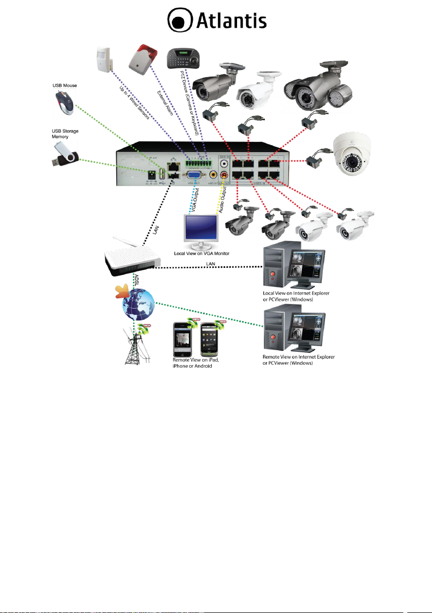
1. PRODUCT OVERVIEW NetCamera Ethernet System TX10Kit(-W)
NetCamera Ethernet System is a complete solution (with standalone DVR and 4 optional IR Cameras) for
local/remote video surveillance, designed to operate in every working environment (domestic or SoHo).
DVR is able to playback locally, on the connected monitor (VGA), up to 4 channels and is able to record
(always, motion detection, manual, time schedule) on the internal 2,5” HDD(into A09-TD410) or 3,5" (into
A09-TD810), using H.264 codec.
The CCD sensor (1/4”), able to work also with a low light intensity of the environment, provides clear and
tidy videos with real colors in each situation (28 IR LEDs down to 0 Lux up to 8 mt). NetCamera uses
ethernet cables for the connection to cameras (power and video/audio are integrated onto the same cable,
supporting category 5/5e up to 100 Meters) it allows to migrate in the future the infrastructure toward IP,
without further costs of wiring, safeguarding the investment.
Finally, it can be remotely managed and controlled at any moment and place, in a simply and intuitive way,
via PC or notebook connected to the Internet (or Intranet) by using any web browser or mobile devices
(iPhone or iPad).
These features, with the included 12 months free Atlantis DynDNS subscription, make NetDVR the ideal
tool for local/remote monitoring/video surveillance.
NetDVR X10
NetDVR is able to playback locally, on the connected monitor (VGA or RCA), up to 4/8 channels and is able
to record (always, motion detection, manual, time schedule) on the internal 3,5” HDD, using H.264 codec.
NetDVR uses ethernet cables for the connection to cameras (power and video/audio are integrated onto
the same cable, supporting category 5/5e up to 100 Meters) it allows to migrate in the future the
infrastructure toward IP, without further costs of wiring, safeguarding the investment.
Finally, it can be remotely managed and controlled at any moment and place, in a simply and intuitive way,
via PC or notebook connected to the Internet (or Intranet) by using any web browser or mobile devices
(Android, iPhone or iPad).
This device (A09-TD810) can be connected with 1 PTZ Camera (RS485), 16 External Sensors and 1 External
Siren.
These features, with the included 12 months free Atlantis DynDNS subscription, make NetDVR the ideal
tool for local/remote monitoring/video surveillance.
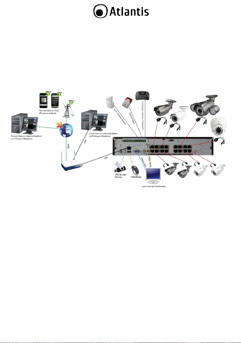
NetDVR 1600
NetDVR is able to playback locally, on the connected monitor (VGA or RCA and using optional modele also
in HDMI), up to 16 channels and is able to record (always, motion detection, manual, time schedule) on the
internal 3,5” HDD, using H.264 codec.
NetDVR uses ethernet cables for the connection to cameras (power and video/audio are integrated onto
the same cable, supporting category 5/5e up to 100 Meters) it allows to migrate in the future the
infrastructure toward IP, without further costs of wiring, safeguarding the investment.
Finally, it can be remotely managed and controlled at any moment and place, in a simply and intuitive way,
via PC or notebook connected to the Internet (or Intranet) by using any web browser or mobile devices
(Android, iPhone or iPad).
This device can be connected with 1 PTZ Camera (RS485), 16 External Sensors and 1 External Siren.
These features, with the included 12 months free Atlantis DynDNS subscription, make NetDVR the ideal
tool for local/remote monitoring/video surveillance.
9
Page 10

Atlantis SpA disclaims any liability whats oever for any end-user use of the Atlantis
product, which fails to comply with applicable state, local, or federal laws.
A09-TD410
A09-TD410
A09-TD410Kit
A09-TD410Kit-W
A09-TD810Kit
A09-TD810Kit-W
DVR (A09-TD410/A09-TD810)
4 Balun
Quick Start Guide
USB Mouse
IR Remote Controller
Adapter AC-DC (12V@5A) for DVR and
Cameras
Cd-Rom with manual, Utility, Software
Warranty Card
DVR (A09-TD410)
4 Cameras (A09-TT420-20-
X)
4 Brackets
4 Balun
Quick Start Guide
USB Mouse
IR Remote Controller
Adapter AC-DC (12V@5A)
for DVR and Cameras
Cd-Rom with manual,
Utility, Software
Warranty Card
DVR (A09-TD810)
4 Cameras (A09-TT420-20-
X)
4 Brackets
4 Balun
Quick Start Guide
USB Mouse
IR Remote Controller
Adapter AC-DC (12V@5A)
for DVR and Cameras
Cd-Rom with manual,
Utility, Software
Warranty Card
A09-TD1600
DVR (A09-TD1600)
4 Balun
Quick Start Guide
USB Mouse
IR Remote Controller
Adapter AC-DC (19V@6.3A) for DVR and Cameras
Cd-Rom with manual, Utility, Software
Warranty Card
1.1 SYSTEM REQUIREMENTS (only for WEB configuration or Live View with Internet Explorer)
Before installing Router, your PC should meet the following:
TCP/IP protocol must be installed on each PC
Web browser, such as Microsoft Internet Explorer 6.0 or later (Active X)
Pentium 4 1800MHz (or equivalent AMD) with 512MB
Graphic Card: 64 MB RAM graphic cards(or equivalent on-board graphic cards)
Windows2000, 2003, XP, Vista, 7
1.2 PACKAGE CONTENTS
Unpack the package and check all the items carefully. Also, keep the box and packing materials in case you
need to ship the unit in the future. The package should contain the following items:
If any item contained is damaged or missing, please contact your local dealer as soon as
possible.
10
Page 11
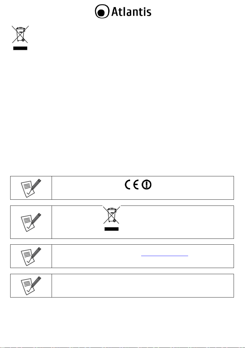
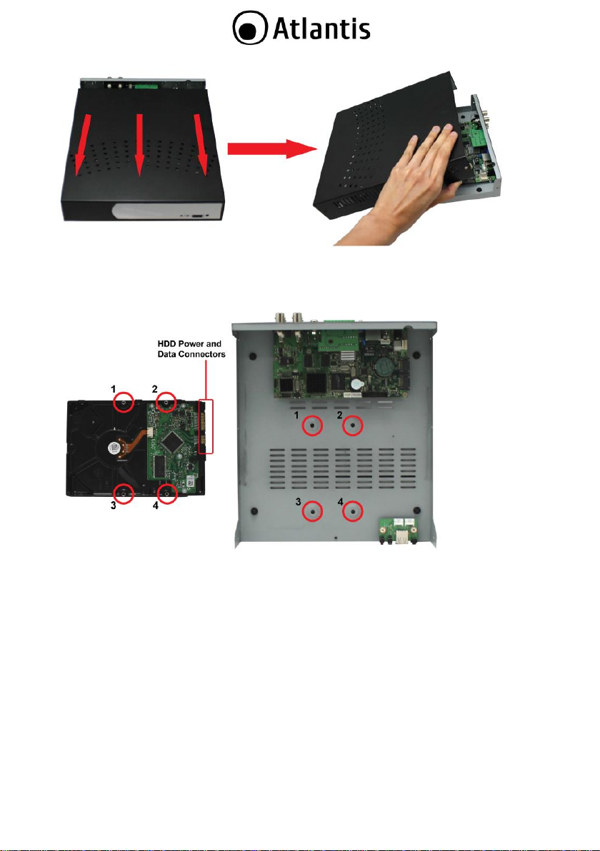
1.3 INSTALLATION(Hard Drive) A09-TD410
Install the hard drive by following steps. Remove the four screws on the bottom side of DVR.
Remove the two screws on the back panel of DVR and lift out the top housing chassis.
Fix the HDD and the cables according to the following diagram. Attach the SATA data and power
cables of the hard disk to their respective ports on the system board (as indicated in the following
illustration).
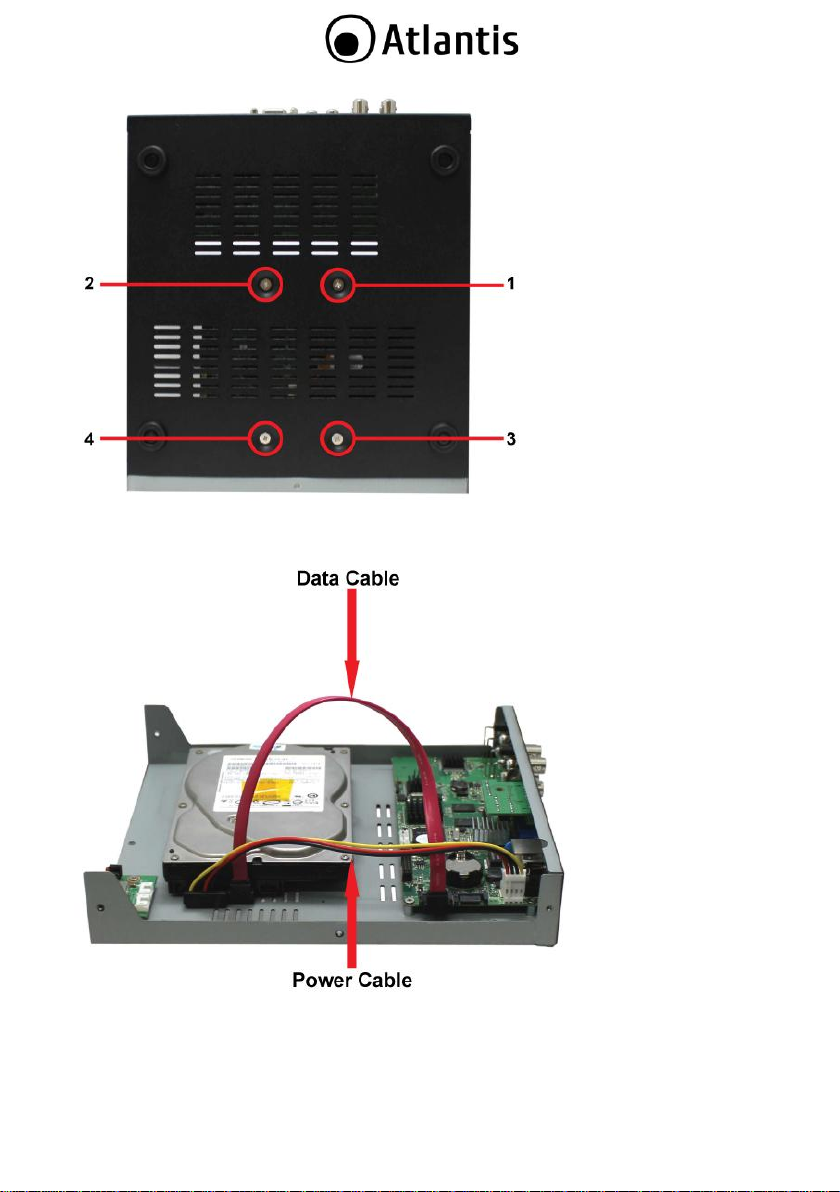
Put the top housing back into place. Secure the casing with the two screws on the rear side of the DVR
and the four screws on the bottom side.
Check if the connectors are properly connected and there is no problem with wiring and close up
cover, and fix it with screws.
11
Page 12
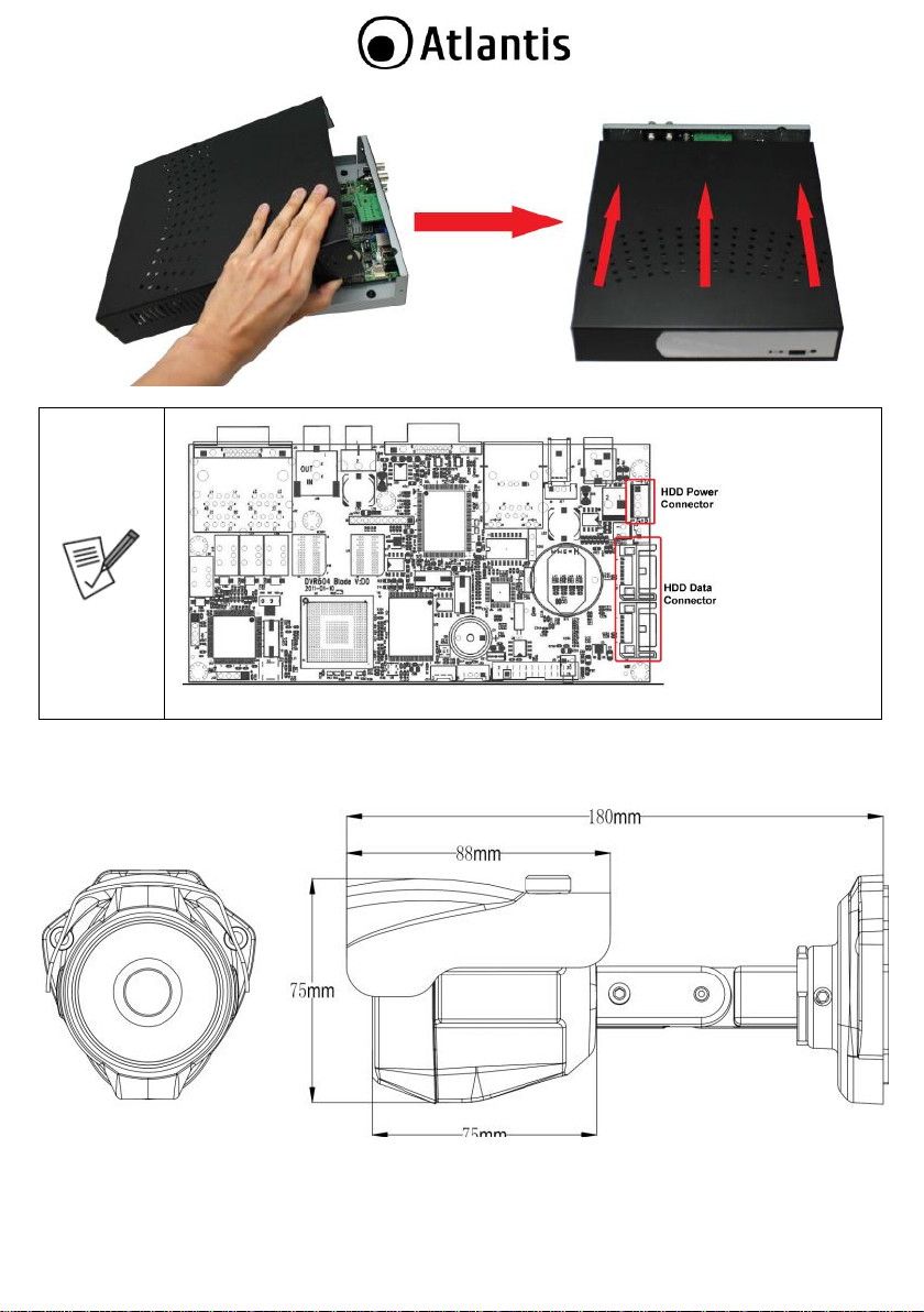
HDD Data
HDD Power Connector
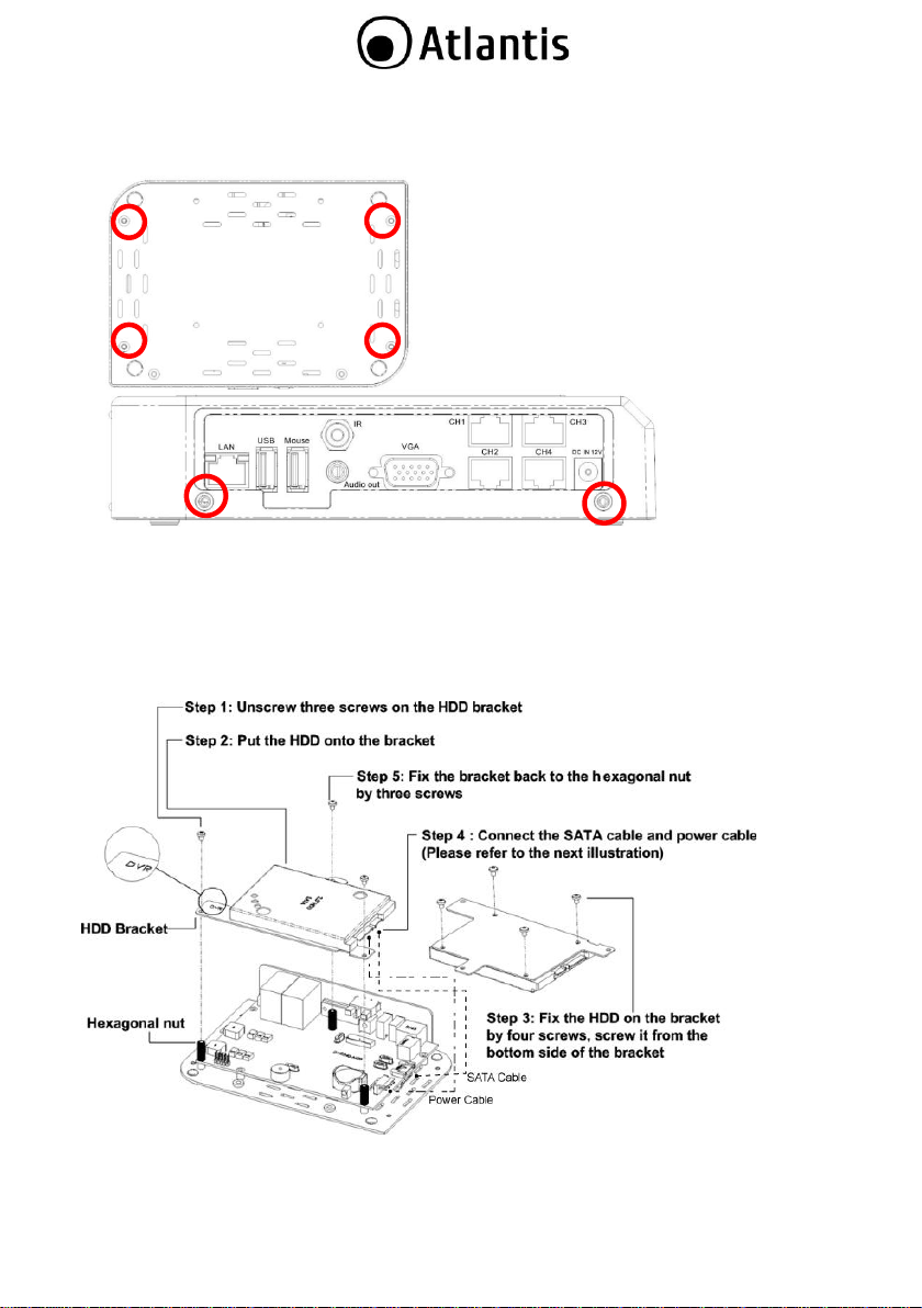
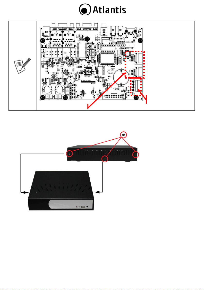
1.4 INSTALLATION(Hard Drive) A09-TD810/A09-TD1600
Install the hard drive by following steps. Unscrew the DVR housing from both sides.
Slide the top cover slightly forward and then lift it out.
12
Page 13
Mount the hard disk on to the bottom chassis. Align the screw sockets as indicated. Note that the side
on which the data and power connectors of the hard disk will be in-line with their respective data and
power ports on the PCB.
Secure the hard disk to the bottom chassis with screws on the opposite side, as shown.
13
Page 14
Attach the hard drive SATA data and power cable from hard drive to the main board connector (shown
in the following picture). Make sure that data and power connectors are also attached to the hard disk.
14
Page 15
Return the top cover back into place. Secure top cover with screws on both sides.
1.5 DIMENSIONS (unit:mm)
15
Page 16
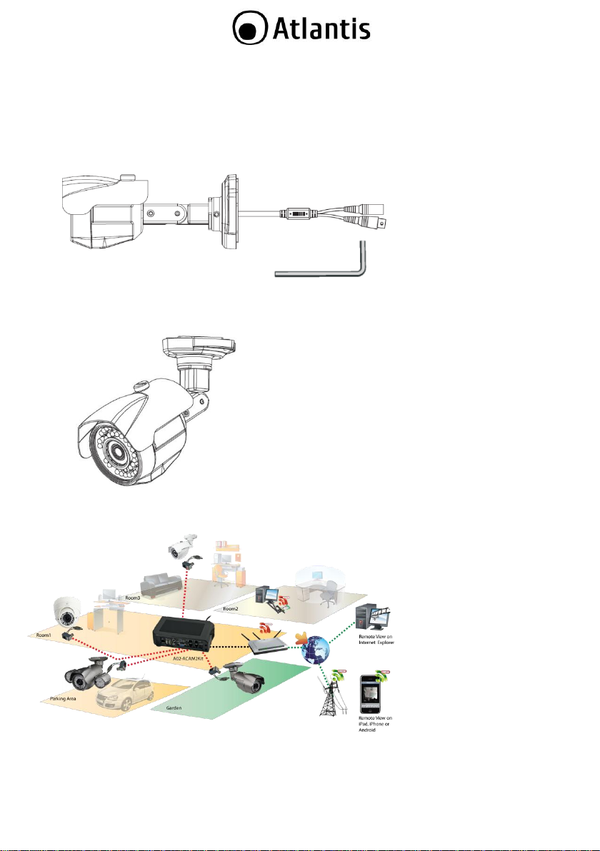
1.6 CABLING
Lift the two mounting rings off the base, making sure that the three mounting screws do not fall off.
Screw two of the base unit screws into the base unit and onto the ceiling/wall
Insert the cable through the base unit and connect the cable.
Screw the remaining base unit screws into the base unit to secure it on the ceiling/wall. Be sure that all
screws are tightened.
Now You can change the camera Pan/Tilt in order to satisfy your installation.
Use the wrench to release the screw, the adjust and move it up/down. Use the wrench to release the
screw and do 360° rotation angle mobilization.
In the end connect the DC Adapter (isn’t included) or power distribution box to the Camera (using a Power
Connector Adapter) or connect directly the device to DVR.
16
Page 17
Do not focus the camera on the sun directly.
Ensure the camera is fixed securely otherwise it may fall and cause injury.
17
Page 18
Connect the power adaptor to turn the DVR on only AFTER all the devices (i.e.
cameras, sensors, mouse, and hard drives) have been connected to their respective
ports.
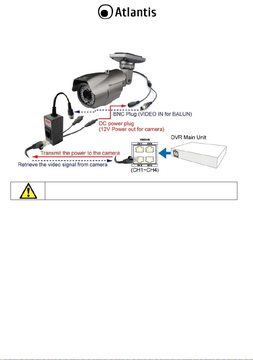
1.7 CONNECT THE CAMERAS to DVR
The specialized video BALUN is used to connect an RJ-45 cable from CH1 – CH4 on the DVR (as shown in
the diagram below). The security camera is connected to the video input (male BNC) and its power plug to
the corresponding socket on the balun.
18
Page 19
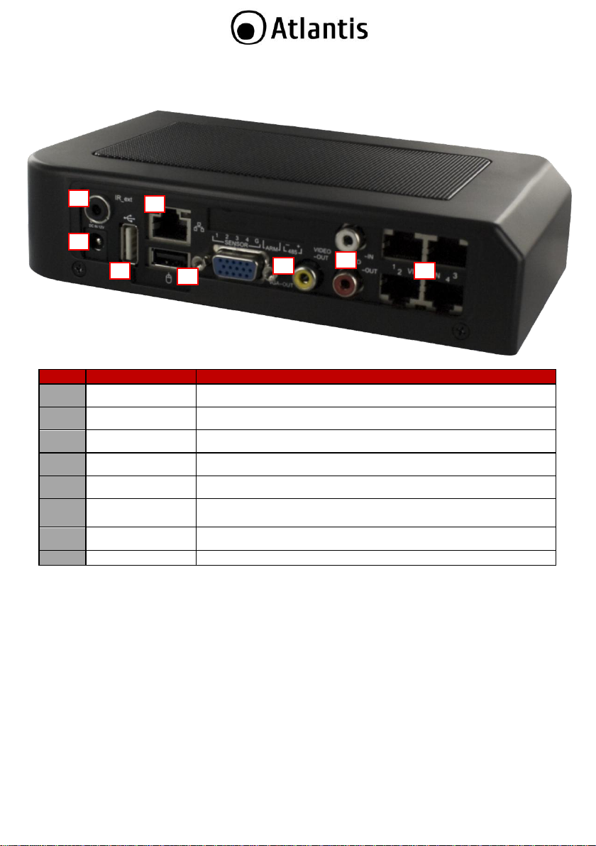
N°
NAME
FUNCTION
1
LAN
RJ45 port for the network cable
2
USB
Memory Stick or External HDD.
3
MOUSE
Mouse port (for USB compatible mouse only)
4
IR
IR extender connector (optional)
5
Audio In/Out
Audio In/Out (RCA).
6
VGA/RCA
Video output port for the security monitor. VGA output (DB-9) port
for the LCD monitor
7
CH1-4
RJ45 connectors for video input: CH1~CH4.
8
DC-IN 12V
DC power port for the power adaptor: DC, 12V@5A.
1 7 2 3 4 5 6
8
1.8 DVR REAR PANEL (A09-TD410)
The rear panel of the DVR contains all of the connectors you will be using.
DVR Cabling procedure:
Connect the 4 video cable (RJ45) connectors
Connect the USB mouse to the USB slot for mouse on the rear panel of the DVR
Connect one end of the network cable (not included) to RJ-45 port on the rear panel of the DVR and
speaker (option)
Connect a VGA cord (not included) from your monitor to the VGA output on the rear panel of your DVR
Plug in power supply to an open outletrts.
19
Page 20

20
Page 21
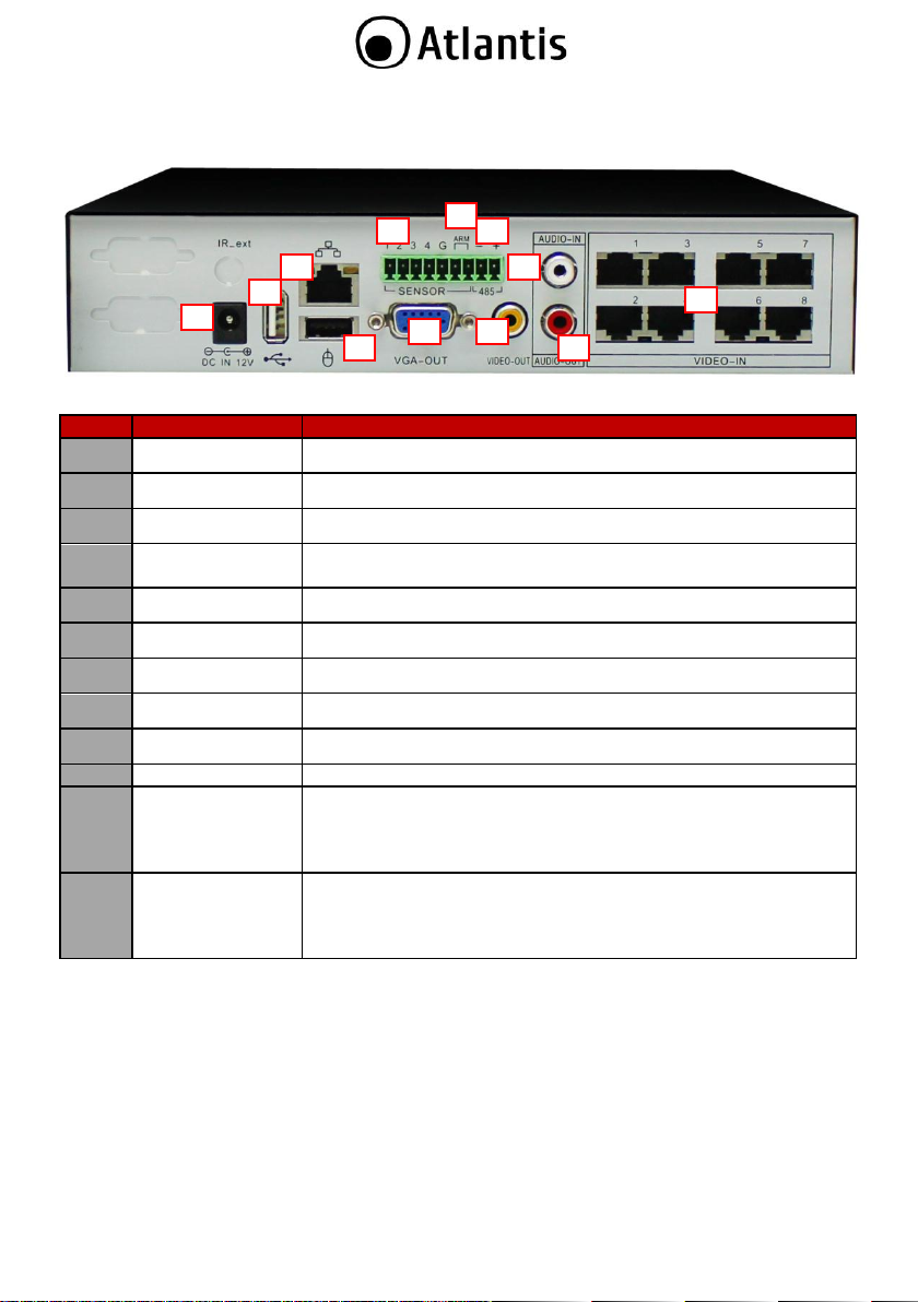
N°
NAME
FUNCTION
1
LAN Ethernet
RJ45 port for the network cable
2
USB Port
Memory Stick or External HDD.
3
Mouse
Mouse port (for USB compatible mouse only)
4
VGA
Video output port for the security monitor. VGA output (DB-9) port
for the LCD monitor
5
Out RCA
Video output port for the security monitor.
6
Audio Out
Audio Out (RCA).
7
Audio In
Audio IN (RCA).
8
CH1-CH8
RJ45 connectors for video input: CH1~CH4.
9
DC-IN 12V
DC power port for the power adaptor: DC, 12V@5A.
10
PTZ(RS485)
RS-485 connector (typically for PTZ cameras and keyboards)
11
Allarm
Connect the alarm indicator to the alarm slots labeled as “ARM” on
the DVR. This supports alarm that can be triggered when an event
has occurred.
Alarm port (Alarm 1+ and Alarm 1-)
12
Sensors
Connect the sensor wires to the sensor slots labeled as “SENSOR”
and numbered 1~4 with a common ground “G” on the DVR. This
device often used with a security camera at the monitoring space.
Sensor ports (marked “1~4”) and a common ground (marked “G”)
1 7 2 3 4 5 6 8 9
10
11
12
1.9 DVR REAR PANEL (A09-TD810)
The rear panel of the DVR contains all of the connectors you will be using.
DVR Cabling procedure:
Connect the 4 video cable (RJ45) connectors
Connect the USB mouse to the USB slot for mouse on the rear panel of the DVR
Connect one end of the network cable (not included) to RJ-45 port on the rear panel of the DVR and
speaker (option)
Connect a VGA cord (not included) from your monitor to the VGA output on the rear panel of your DVR
Plug in power supply to an open outlet
21
Page 22
22
Page 23
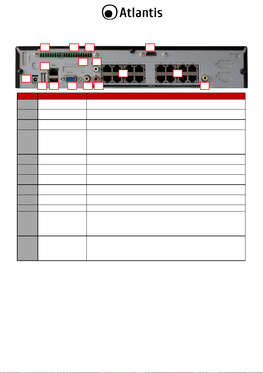
N°
NAME
FUNCTION
1
LAN Ethernet
RJ45 port for the network cable
2
USB Port
Memory Stick or External HDD.
3
Mouse
Mouse port (for USB compatible mouse only)
4
VGA
HDMI (optional)
Video output port for the security monitor. VGA output (DB-9) port
for the LCD monitor
In order to add HDMI feature, please ask the following product code
to your supplier (Codice A09-TD1600-HDMI)
5
Out RCA
Video output port for the security monitor.
6
Audio Out
Audio Out (RCA).
7
Audio In
Audio IN (RCA).
8
CH1-CH16
RJ45 connectors for video input: CH1~CH16.
9
DC-IN 19V
DC power port for the power adaptor: DC, 19V@6.3A.
10
PTZ(RS485)
RS-485 connector (typically for PTZ cameras and keyboards)
11
Allarm
Connect the alarm indicator to the alarm slots labeled as “ARM” on
the DVR. This supports alarm that can be triggered when an event
has occurred.
Alarm port (Alarm 1+ and Alarm 1-)
12
Sensors
Connect the sensor wires to the sensor slots labeled as “SENSOR”
and numbered 1~16 with a common ground “G” on the DVR. This
device often used with a security camera at the monitoring space.
Sensor ports (marked “1~16”) and a common ground (marked “G”)
1 7 2 3 4 5 6 8 9
10
11
12 5 4 8 12
1.10 DVR REAR PANEL (A09-TD1600)
The rear panel of the DVR contains all of the connectors you will be using.
23
Page 24
DVR Cabling procedure:
Connect the 4 video cable (RJ45) connectors
Connect the USB mouse to the USB slot for mouse on the rear panel of the DVR
Connect one end of the network cable (not included) to RJ-45 port on the rear panel of the DVR and
speaker (option)
Connect a VGA cord (not included) from your monitor to the VGA output on the rear panel of your DVR
Plug in power supply to an open outlet
24
Page 25
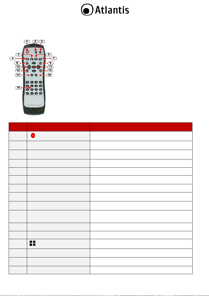
No
Button / Name
Function in DVR Mode
1
REC
Start or stop recording / backup.
2
DVR
Switch to DVR mode
3
PTZ
Switch to PTZ mode
4
REW
Rewind through video
5
STOP
Stop playback or backup
6
II PAUSE
Pause recording of playback
7
FF
Fast forward through video
8
► PLAY
Start video playback
9
MENU
Enter or exit a menu
10
▲(UP) ▼(DOWN)
(LEFT) ►(RIGHT)
Move through lists or change the settings of choices
11
(Enter/Select)
Change and confirm values
12
AUTO
Start automatic screen view rotation
13
MODE
Changes to split-screen mode
14
- ZOOM OUT
(Not available in DVR mode)
15
+ ZOOM IN
(Not available in DVR mode)
16
1,2,---- (Channels)
Selects the channel to view in full screen
1.11 REMOTE CONTROL
The remote control may be used as an alternative to the mouse.
25
Page 26
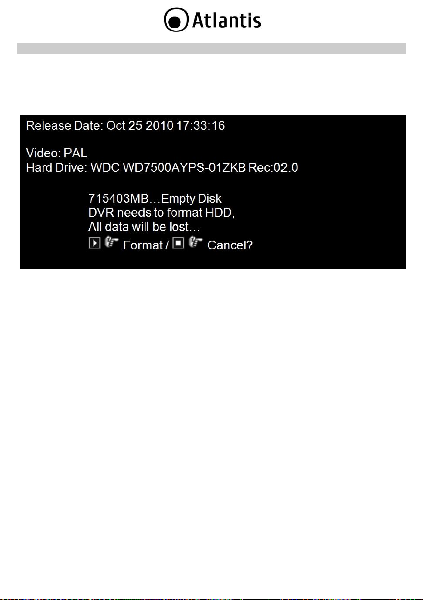
2. STARTING UP THE DVR SYSTEM
2.1. FORMAT THE HARD DRIVE
The DVR is ready for running after all peripherals have been properly installed. Connect the power adaptor
to turn the DVR on. The DVR may take a few second to startup. When the hard drive is detected by the
system, it will ask whether or not you would like to format it. Refer to the conditions stated below to
determine which course of action to take.
Format the hard drive if: It is the initial installation of the hard drive (1st time to install the HDD in
the DVR).
Do not format the hard drive if: The hard drive has already been formatted by the DVR and not
formatted by other devices.
26
Page 27
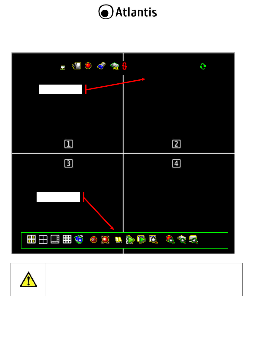
The Drag and Drop Channel Swap enables swap the channel displays using your mouse.
No need to interchange the RJ45 connectors. This function is also applicable for all kinds
of Split View.
1% 2010/06/06 15:37:47
State Bar
Control Bar
2.2. HOME SCREEN
The Home Screen is the starting point for many functions and applications. It allows you to setup, access,
and control the surveillance video data. You may think of this screen as a vantage point to give you instant
access to video information and DVR functions.
27
Page 28
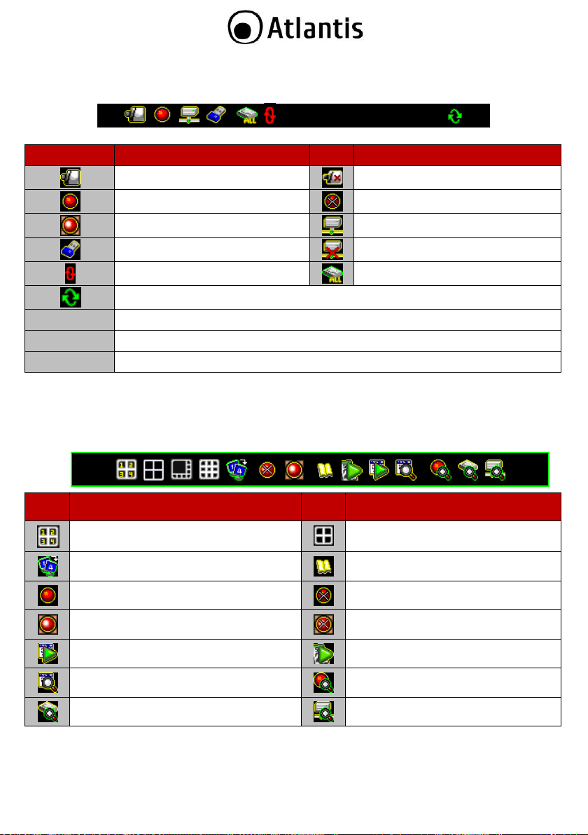
Icon
Function
Icon
Function
Camera is working.
No signal from camera.
Recording.
Recording Stop.
Force Record Start.
Network connected.
USB disk connected.
Network disconnected.
Hard drive overwrite enabled.
Hard drive status.
Channel display rotation enabled.
XX%
Percentage of hard drive already used.
2010/06/03
Current date.
15:37:47
Current time.
Icon
Function
Icon
Function
Load default channel display location.
4-channel split view.
Auto channel rotation.
Enter main menu.
Start recording.
Stop recording.
Start forced recording.
Stop forced recording.
Playback menu.
Calendar Menu.
Event search.
Recording information.
Hard drive information.
Network information.
1% 2010/06/06 15:37:47
State Bar Information
The State Bar displays the status and notification icons of the surveillance system.
Control Bar Information
The Control Bar may be used to access channels and their related applications.
28
Page 29
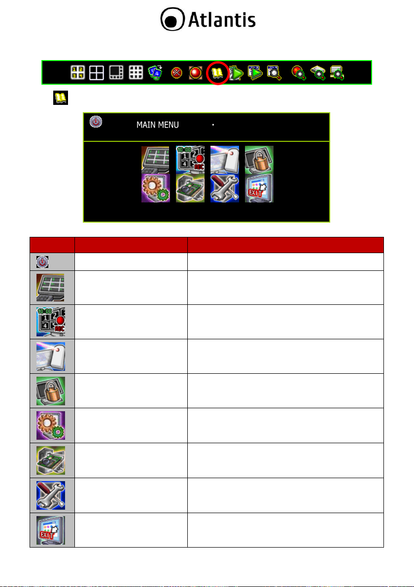
Icon
Name
Function
DVR Power Supply
To reboot or shutdown the DVR system.
Channel Setup
Set the channel display, record, channel name and
video color adjustment.
Record Setup
Set the record schedule, video performance and
quality.
Detector Setup
Set the motion, sensor and alarm mode.
Authentication Setup
Set the login account, password and the
authentication.
System Setup
Set the status icons display, languages, date/time,
rotation time, button beep tone, input device speed,
and other relevant system features.
Hardware Setup
Configures error message checks, hard drive
information, overwrite settings, network settings,
PTZ/Keyboard, Audio and screen settings.
Utility/Tools
These are used to format USB devices, to update
firmware, to export event logs, and to restore
system settings.
Exit Main Menu
Exit the main menu.
Main Menu
Press the icon to enter the “Main Menu”. The default password is 123456.
29
Page 30

CHANNEL SETUP
Channel Number
Basic Setting
Standard Color Adjustment
Special Color Adjustment
Click on the icon to expand the menu and view its contents.
Click on the icon to minimize the menu contents.
Click on the right button of your mouse to go back to the upper menu.
CHANNEL SETUP
Channel Number
Basic Setting
Active Channel
[ ON]
Record Channel
[ ON]
Hidden Channel
[ NO]
Channel Name
[No Definition]
Rotation Time
▐▬▬▬▬▬ [2Sec]
Image Position Adjustment
Standard Color Adjustment
2.3 Channel Setup Click the “Channel Setup” on the Main Menu. The screen will display the menu shown in the following
illustration.
Channel Number
The Channel Number is used to designate to which channel or channels the settings will apply.
Press the icon (for 4Ch) or the icon (for 8Ch). This icon will turn orange and the settings will
be applied to all channels.
Select the icons “ ” ~ “ ” (for 4Ch) or “ ” ~ “ ” (for 8Ch) to individually setup of each
channel. The channel icon will turn green when selected and will turn to white when not selected.
Basic Settings
Active Channel: Activate one channel or all of the channels. Active channels are ready for recording
and are displayed on the screen.
30
Page 31

“ON” – Activates selected channel. The channel number icon turns to orange.
“OFF”- Disables selected channel. The channel number icon turns to gray.
Record Channel:This parameter sets one channel or all of the channels to record videos. An active
channel will be displayed on screen even when it is not recording.
“ON” – recording
“OFF” – not recording
Hidden Channel: Set whether or not to display one or all channels on screen. The channel will
continue to record regardless of it being hidden or not.
“ON” – Hide the channel on screen. The channel square turns to black and channel number icon
turns to white.
“OFF”- Unhide the channel or channel is visible.
Channel Name: Designate a name for each channel. The channel name is limited to 24 characters.
Press the icon [ Default Name] to select a channel name from the list defined by the system:
Room, Hall, Door, Lift, Area, Floor, Entry, and Point.
Press the icon “ ” to switch to big letters.
Press the icon “ ” to enter the channel name. The channel name will appear on the channel
square.
You may also define the name by using buttons on IR remote. Kindly refer to the Hardware
Installation and Operation Manual of this DVR for the diagrams.
Rotation Time: Sets the period (with a range of 2 to 30sec) of full screen display for each channel.
Image Position Adjustment: The steps to adjust the position of display on the monitor are as
follows:
Select the icon “ ” (for 4Ch) or “ ” (for 8Ch) to adjust the display position of all channels in
4/8/16-split view at one time.
OR
Select the icons “ ” ~ “ ” (for 4Ch) or “ ” ~ “ ” (for 8Ch) to individually set the image
position of each channel.
The following figure (for 4Ch) will appear when you enter the “Image Position Adjustment”:
Adjust the image position by mouse left-click follow the direction change of cursor icon up/
down/ right/ left.
Press [ Default] to load or to restore to the default location.
31
Page 32

CHANNEL SETUP
Channel Number
Basic Setting
Standard Color Adjustment
Brightness
◄▬▬▐▬▬► [10]
Contrast
▬▬▐▬▬ [10]
Hue
▬▬▐▬▬ [16]
Saturation
▬▬▐▬▬ [16]
Sharpness
▬▬▐▬▬ [8]
Special Color Adjustment
CHANNEL SETUP
Channel Number
Basic Setting
Standard Color Adjustment
Special Color Adjustment
Activate Special Color
[ Disable]
Start Time
▬▬▐▬▬ [06:00]
End Time
▬▬▐▬▬ [21:00]
Brightness
▬▬▐▬▬ [12]
Contrast
▬▬▐▬▬ [12]
Hue
▬▬▐▬▬ [16]
Saturation
▬▬▐▬▬ [20]
Sharpness
▬▬▐▬▬ [12]
Standard Color Adjustment
Adjusts the video color parameters for each channel or simultaneously for all channels.
Brightness: Default is 10. Press the button “◄ / ►” to adjust the brightness from 1 to 20.
Contrast: Default is 10. Press the button “◄ / ►” to adjust the contrast from 1 to 20.
Hue: Default is 16. Press the button “◄ / ►” to adjust the hue from 1 to 32.
Saturation: Default is 16.. Press the button “◄ / ►” to adjust the saturation from 1 to 32.
Sharpness: Default is 8. Press the button “◄ / ►” to adjust the sharpness from 1 to 16.
Special Color Adjustment
Special Color Adjustment applies to video color parameters and designates the setting for a specified period
for an individual channel or for all channels.
Activate Special Color:
32
Page 33

RECORD SETUP
Auto Record
◄30Sec►
Activate Performance Gains [ Enable ]
Record Schedule
Total Power : 480/480 (Power/Sec)
Auto Settings Adjustment
Channel Recording Setup
Channel Number
Record Resolution [Middle Res (Half D1)]
Video Quality [Standard]
Record Frame Rate
[30]
Record Performance Gains [ YES]
“ Disable” (Default): Disable Special Color Adjustment.
“ Enable”: Enable Special Color Adjustment
Start Time: The start time for the special color setting.
End Time: The end time for the special color setting.
Brightness: Default is 10. Press the button “◄ / ►” to adjust the brightness from 1 to 20.
Contrast: Default is 10. Press the button “◄ / ►” to adjust the contrast from 1 to 20.
Hue: Default is 16. Press the button “◄ / ►” to adjust the hue from 1 to 32.
Saturation: Default is 16.. Press the button “◄ / ►” to adjust the saturation from 1 to 32.
Sharpness: Default is 8. Press the button “◄ / ►” to adjust the sharpness from 1 to 16.
2.4 Record Setup
Click “Record Setup” on the Main Menu.
ù
Auto Record is utilized to set the period (OFF, 10Sec, 20Sec, 30Sec, 40Sec, 50Sec or 60Sec) within
which the DVR will automatically start recording. Default value is “30Sec”. This feature is particularly
useful in automatically re-starting your DVR recording in case of an abnormal shut down. The DVR
will not re-start recording when set this function “OFF”.
Activate Performance Gains: The function enables system auto increase the recording power to the
heavy loading channel from the not triggered or not recording channels. Enable this function makes
“Record Performance Gains” at “Channel Recording Setup” is validated.
33
Page 34

When “Motion Mode” is set for the recording schedule. Remember to complete the
“Motion Setup” at the main menu of “Detector Setup” - otherwise it will not be able to
record during the period set on “Motion Mode”.
When “Sensor Mode” is set for the recording schedule. Remember to complete the
“Sensor Setup” at the main menu of “Detector Setup” - otherwise it will not be able to
record during the period set on “Sensor Mode”.
Press the icon “ ” to set the recording mode globally: the whole week (7 days) and the
whole day (24 hours) are in the same mode throughout.
The following example shows that the entire week (all 7 days) and the whole day (all 24
hours) are set to the “Motion” recording mode.
Select “Motion” recording mode, press the icon “ ” and press “””.
Press the icon “ ” (located after the name of each day) to set every hour of an entire
day to operate in the same mode.
The following example shows that on Sunday, the whole day is set to the “Time”
recording mode.
Select “Time” recording mode, press the icon “ ” and press “””.
Press the icon “ ” to set the same mode for a specified time every day.
The following example shows that from 23:00 to 24:00 (11:00pm to 12:00mn) everyday
there is no recording (set to “None” recording mode).
Select “None” recording mode, press the icon “ ” and press “””.
You can also specifically set the recording mode for a particular time and day.
The following example shows that on Sunday, from 19:00 to 24:00 (7:00pm to
Record Schedule
Record Schedule is a menu charting the recording schedule of a particular channel or all channels for the
whole day (24 hours) and the entire week (7 days).
Default setting is “Time Record”.
Channel Number
Select the icon “ ” (for 4Ch) or “ ” (for 8Ch) to setup for all channels at one time.
Select the icons “ ” ~ “ ” (for 4Ch) or “ ” ~ “ ” (for 8Ch) to individually setup of each
channel.
Recording Mode Select
There are five recording modes:
None: Indicates that the channel is set to not record during this duration
Time: Indicates that the channel is set to continuously record during this duration
Motion: Indicates that the channel is set to motion-triggered recording during this duration
Sensor: Indicates that the channel is set to record when the sensor is triggered during this
duration
Motion+Sensor: Indicates that the channel is set to detect either triggering events caused
by motion or from the sensor
34
Page 35

12:00mn), and on Friday, from 2:00 to 4:00 (2:00am to 4:00am), are set to the “Time”
recording mode.
Select the recording mode first. Move the cursor and click the icon “ ”, “ ”, “ ”, “ ”
or “ ” to change mode on the timetable.
Select “Time” recording mode, move the cursor and click the period of icons “ ”
change to “ ” and press “””.
The Total Power for 4Ch and 8Ch is 240/240 (Power / Sec) in NTSC. For PAL,
the Total Power for 4Ch and 8Ch is 200/200 (Power / Sec).
RECORD SETUP
Auto Record ◄30Sec►
Active Performance Gains [ Enable]
Record Schedule
Total Power: 480/480 (Power / Sec)
Auto Settings Adjustment
Channel Recording Setup
Channel Number
Record Resolution [ Middle Res (Half D1) ]
Video Quality [Standard]
Record Frame Rate [15]
Record Performance Gains [ YES]
Total Power
Total Power: 480/480 (Power / Sec): It shows the number of recording power that has been allocated and
the total number of recording power.
To distribute the recording power into four channels by click the total power (as indicated above).
35
Page 36

RECORD SETUP
Total Power: 480/480 (Power/Sec)
Channel Select ◄ ······ ►
Resolution Quality Framerate
◄Half D1► [Standard] [15]
[ Half D1 ] [Standard]
[15]
[ Half D1 ] [Standard]
[15]
[ Half D1 ] [Standard]
[15]
[ Half D1 ] [Standard]
[15]
[ Half D1 ] [Standard]
Video Resolution, Quality and Frame Rate Setting for each channel
Resolution: Press the button “◄ / ►” to adjust the resolution from CIF, Half D1 and D1 for individual
channel.
Quality: Press the button “◄ / ►” to adjust the resolution from Lowest, Low, Standard, High and
Highest for individual channel.
Frame rate: Press the button “◄ / ►” to adjust the frame rate from 0 to max value for individual
channel. The DVR will not be recording if the frame rate value is 0.
Auto Settings Adjustment
This function can automatically allocate the recording power under the selected record resolution.
When all the channels are set at the same resolution, the “Auto Settings Adjustment” can automatically
allocate the frame rate to every channel. When the setting applies to a specific channel or to specific
channels with a particular resolution, video quality or frame rate the “Auto Settings Adjustment”
feature automatically allocates the remaining frame rate among the other channels.
Channel Recording Setup
The Channel Recording Setup is used to adjust the resolution, quality, frame rate and performance
gains of recording.
Channel Number
Select the icon “ ” (for 4Ch) or “ ” (for 8Ch) to setup all channels at one time.
Select the icons “ ” ~ “ ” (for 4Ch) or “ ” ~ “ ” (for 8Ch) or to individually
setup of each channel.
Recording Resolution: Select the recording resolution for each or all channels as:
D1: 704*480 / 60fps (NTSC); 704*576 / 50fps (PAL)
Half D1: 704*240 / 120fps (NTSC); 704*288 (PAL) (Default)
CIF: 352*240 / 120fps (NTSC); 352*288 (PAL)
Video Quality: Video image quality settings can be Highest, High, Standard, Low, and Lowest.
Default is Standard. Higher video quality provides a much clearer image for playback but can
utilize a much larger hard drive space with a larger file size.
Record Frame Rate: The recording frame rate for each or all channels may be set from 0~30
fps for NTSC or 0~25 fps for PAL. If the frame rate is set to 0, the DVR will not be recording.
36
Page 37

RECORD SETUP
Auto Record [30Sec]
Active Performance Gain [ Enable ]
Record Schedule
Total Frame Rate: 480/480 (Power / Sec)
Auto Settings Adjustment
Channel Recording Setup
Channel Number
Record Resolution [Middle Res (Half D1)]
Video Quality [Standard]
Record Frame Rate [15]
Record Performance Gains [ YES]
Recording Performance Gains: The “Record Performance Gains” enables the system to
automatically increase the system power on the heavy loading channel, taking power from the untriggered, unutilized or non- recording channels. This function can apply for one or all channels.
37
Page 38

DETECTOR SETUP
Channel Number
Alarm Setup
Light Detect Mode [Sensitivity OFF]
Light Detect Alarm Mode [Mute]
Blind Detect Mode [Sensitivity OFF]
Blind Detect Alarm Mode [ Buzzer-Short]
Video Loss Mode [ Disable]
Video Loss Alarm Mode [ Buzzer-Short]
Motion Setup
DETECTOR SETUP
Channel Number
Alarm Setup
Light Detect Mode [Sensitivity OFF]
Light Detect Alarm Mode [Mute]
Blind Detect Mode [Sensitivity OFF]
Blind Detect Alarm Mode [ Buzzer-Short]
Video Loss Mode [ Disable]
Video Loss Alarm Mode [ Buzzer-Short]
Motion Setup
Sensor Setup
2.5 Detector Setup
Click “Detector Setup” on the Main Menu.
Channel Number
Select the icon “ ” (for 4Ch) or “ ” (for 8Ch) to setup for all channels at one time.
Select the icons “ ” ~ “ ” (for 4Ch) or “ ” ~ “ ” (for 8Ch) to individually setup of each
channel.
Alarm Setup
Alarm Setup is accessed to configure the alarm mode of each channel, individually, or for all channels,
simultaneously.
38
Page 39

Light Detect Mode: This mode will be triggered when the video input and when the light from the
environment becomes faint or becomes dark unexpectedly (close to complete darkness) or there is
direct exposure by intense light. This mode is related to the ambient lighting of the DVR. The light
intensity settings will have no effect when using the IR cameras. Choose any of the following settings
to adjust the sensitivity of light detection:
Sensitivity OFF: No sensitivity
Sensitivity Low: Low sensitivity level
Sensitivity Normal: Normal sensitivity level
Sensitivity High: High sensitivity level
Sensitivity Highest: Highest sensitivity level
Light Detect Alarm Mode: Select the alarm mode when the Light Detect Mode is triggered.
Mute: No beep whatever loss of light or not.
Buzzer-Short: Slow beeping sound from buzzer on main board.
Buzzer-Long: Fast beeping sound from buzzer on main board.
Alarm-Short: Short sound coming from the alarm.
Alarm-Long: Prolonged sound coming from the alarm.
Blind Detect Mode: This mode will be triggered when there is no video input (in total darkness)
whether the security camera is purposefully being covered or there is a direct exposure to intense
light. This detects if there is a deliberate attempt to hide the view of the camera. The light intensity
settings will have no effect when using the IR cameras.
Choose any of the following settings to adjust the sensitivity of blind detection:
Sensitivity OFF: No sensitivity
Sensitivity Low: Low sensitivity level
Sensitivity Normal: Normal sensitivity level
Sensitivity High: High sensitivity level
Sensitivity Highest: Highest sensitivity level
Blind Detect Alarm Mode: Select the alarm mode when the Blind Detect Mode is triggered.
Mute: No beep whatever loss of light or not.
Buzzer-Short: Slow beeping sound from buzzer on main board.
Buzzer-Long: Fast beeping sound from buzzer on main board.
Alarm-Short: Short sound coming from the alarm.
Alarm-Long: Prolonged sound coming from the alarm.
Video Loss Mode: The Video Loss Mode is for detecting the loss of the camera video input.
Enable: Activates video loss detection
Disable: Deactivates video loss detection
Video Loss Alarm: Select the alarm mode when the Video Loss Mode is triggered.
Mute: No beep whatever loss of light or not.
Buzzer-Short: Slow beeping sound from buzzer on main board.
Buzzer-Long: Fast beeping sound from buzzer on main board.
Alarm-Short: Short sound coming from the alarm.
Alarm-Long: Prolonged sound coming from the alarm.
39
Page 40

Remember to setup the motion mode period on “Record Schedule” at the main menu of
“Record Setup” after completing “Motion Setup”. Otherwise, the system will be recording
in the default schedule recording mode.
Remember to specify the area you would like monitor using the “Motion Area Setup”
screen. Click on a particular channel you would like to set and then click on Motion Area
Setup to define the particular area you would like to monitor.
DETECTOR SETUP
Channel Number
Alarm Setup
Motion Setup
Record Detection Activate [ Enable]
Motion Mode [Sensitivity Normal]
Record Time [10Sec]
Alarm Mode [Mute]
Alarm Time [10Sec]
Trigger Full Screen [ OFF]
Trigger Type [Initial Trigger]
Motion Area Setup
Sensor Setup
Motion Setup
Motion Setup is accessed to configure the motion mode for the DVR channels.
Record Detection Activate (Motion Setup): This feature activates the motion setup (allowing you
to detect unusual movements) and enables the system to log motion-triggered events even when your
DVR setting is in “Time Recording” mode.
Enable: Activates motion-triggered detection even when DVR is in a different recording
mode. When enabled, a blinking motion icon will be found alongside the Time Recording mode
icon when motion is detected.
Disable: Deactivates motion-triggered detection even when DVR is in a different recording
mode
40
Page 41

1% 2010/06/06 15:37:47
Time Recording
Mode Icon
Blinking Motion Icon
[“Motion Record Detection
Activate” is enabled]
Motion Mode: Choose any of the following settings to adjust the motion sensitivity parameter:
Sensitivity OFF: No sensitivity
Sensitivity Low: Low sensitivity level
Sensitivity Normal: Normal sensitivity level
Sensitivity High: High sensitivity level
Sensitivity Highest: Highest sensitivity level
Record Time: Set the recording time when the Motion Mode is triggered. The recording time as 5sec,
10sec, 15sec, 20sec, 25sec, 30sec, 45sec, 60sec, 90sec, 120sec, 150sec or 180sec.
Alarm Mode: Select the alarm mode when Motion Mode is triggered.
Mute: No beep whatever loss of light or not.
Buzzer-Short: Slow beeping sound from buzzer on main board.
Buzzer-Long: Fast beeping sound from buzzer on main board.
Alarm-Short: Short sound coming from the alarm.
Alarm-Long: Prolonged sound coming from the alarm.
Alarm Time: The Alarm Time is the duration of the beep and may be set to: “Nonstop”(no stop),
5sec, 10sec, 15sec, 20sec, 25sec, 30sec, 35sec, 40sec, 45sec, 50sec, 55sec or 60sec.
41
Page 42

MOTION SETUP
█ █ █ █ █ █ █ █ █ █ █ █ █ █ █ █ █ █ █
█ █ █ █ █ █ █ █ █ █ █ █ █ █ █ █ █ █ █
█ █ █ █ █ █ █ █ █ █ █ █ █ █ █ █ █ █ █
█ █ █ █ █ █ █ █ █ █ █ █ █ █ █ █ █ █ █
█ █ █ █ █ █ █ █ █ █ █ █ █ █ █ █ █ █ █
█ █ █ █ █ █ █ █ █ █ █ █ █ █ █ █ █ █ █
█ █ █ █ █ █ █ █ █ █ █ █ █ █ █ █ █ █ █
█ █ █ █ █ █ █ █ █ █ █ █ █ █ █ █ █ █ █
█ █ █ █ █ █ █ █ █ █ █ █ █ █ █ █ █ █ █
All Select
All Deselect
Trigger Full Screen: Trigger Full Screen is the duration of the of full-screen display when a channel
is triggered.
This may be set to a period between 1 to 30 seconds.
OFF: It will not display on full screen when the channel has been triggered. Also,
Trigger Type: There are two trigger types: Initial Trigger and Continuous Trigger.
Motion Area Setup: The Motion Setup allows the user to block multi areas on screen for every single
the trigger area will turn to a red color.
Initial Trigger: When channel has been triggered, the triggering event will be displayed on full
screen for the duration of the period set in Trigger Full Screen. During that period, this channel
will ignore any other triggering events.
Continuous Trigger: When channel has been triggered, the triggering event will be displayed on
full screen for the duration of the period set in Trigger Full Screen. The channel is, however, still
actively monitoring during that period. Should there be a new triggering event, this channel will
display the more recent event and restart the display period.
channel as motion detection area. Select a channel to set.
All Select: Highlights the entire view displayed on the screen (as seen by the camera)
All Deselect: Removes the selection from the entire view displayed on the screen (as seen
by the camera)
42
Page 43

There will be no response in Motion Mode when the Motion Area Setup has not been
completed.
Remember to set up the sensor mode recording for your desired period on the “Record
Schedule” menu in “Record Setup” after completing “Sensor Setup”. Otherwise, the
system will still be recording in the default recording mode.
MOTION SETUP
□ □ □ □ □ □ □ □ □ □ □ □ □ □ □ □ □ □ □ □
□ □ □ □ □ □ □ □ □ □ □ □ □ □ □ □ □ □ □ □
□ □ □ □ □ □ □ □ □ □ □ □ □ □ □ □ □ □ □ □
□ □ □ □ □ □ □ □ □ □ □ □ □ □ □ □ □ □ □ □
□ □ □ □ □ □ □ □ □ □ □ █ █ █ █ █ █ □ □ □
□ □ □ □ □ □ □ □ □ □ □ █ █ █ █ █ █ □ □ □
□ □ □ □ □ □ □ □ □ □ □ █ █ █ █ █ █ □ □ □
□ □ □ □ □ □ □ □ □ □ □ █ █ █ █ █ █ □ □ □
□ □ □ □ □ □ □ □ □ □ □ □ □ □ □ □ □ □ □ □
DETECTOR SETUP
Channel Number
Alarm Setup
Motion Setup
Sensor Setup
Record Detection Activate [ Enable]
Sensor Mode [ Disable]
Sensor Device Setup
Record Time [15Sec]
Alarm Mode [Mute]
Alarm Time [10Sec]
Trigger Full Screen [ OFF]
Use the mouse to move around and select the area. After positioning, click on the right button of the
mouse to save it.
Sensor Setup
Sensor Setup is accessed to configure the sensor mode for each channel or all channels.
43
Page 44

The sensors need to be properly mapped to a channel and set according to their
operation characteristics (i.e. normally open or normally closed) when using Record
Detection Activate in the Sensor Setup.
1% 2010/06/06 15:37:47
Time Recording
Mode Icon
Blinking Sensor Icon
[“Sensor Record Detection
Activate” is enabled and the
sensor has been triggered]
Record Detection Activate (Sensor Setup): This feature activates the sensor setup (allowing you
to detect unusual movements picked up by the sensor) and enables the system to log sensor-triggered
events even when your DVR setting is in “Time Recording” mode.
Enable: Activates sensor-triggered detection even when DVR is in a different recording mode.
When enabled, a blinking sensor icon will appear beside the Time Recording mode icon once the
sensor is tripped.
Disable: Deactivates sensor-triggered detection even when DVR is in a different recording
mode (i.e. Time Recording Mode)
Sensor Mode: This parameter enables or disables sensor mode detection.
Enable: Activates sensor mode for Sensor Recording Mode
Disable: Deactivates sensor mode for Sensor Recording Mode
Sensor Device Setup: This feature is to easily map a sensor port to a particular channel without
having to remove any wires. Click on a channel you would like to map with a sensor. Select whether
the sensor type is normally open or closed. It depends on the characteristics of the sensor you intend
to use.
44
Page 45

SENSOR DEVICE SETUP
Restore Default Setting
Channel Select
[ ······ ]
Normal – Open: The sensor type is in a normally open state.
Normal – Close: The sensor type is in a normally closed state.
Record Time: Set the recording time when the Motion Mode is triggered. The recording time as 5sec,
10sec, 15sec, 20sec, 25sec, 30sec, 45sec, 60sec, 90sec, 120sec, 150sec or 180sec.
Alarm Mode: Select the alarm mode when Motion Mode is triggered.
Mute: No beep whatever loss of light or not.
Buzzer-Short: Slow beeping sound from buzzer on main board.
Buzzer-Long: Fast beeping sound from buzzer on main board.
Alarm-Short: Short sound coming from the alarm.
Alarm-Long: Prolonged sound coming from the alarm.
Alarm Time: The Alarm Time is the duration of the beep and may be set to: “Nonstop”(no stop),
5sec, 10sec, 15sec, 20sec, 25sec, 30sec, 35sec, 40sec, 45sec, 50sec, 55sec or 60sec.
Trigger Full Screen: Trigger Full Screen is the duration of the of full-screen display when a channel
is triggered.
This may be set to a period between 1 to 30 seconds.
OFF: It will not display on full screen when the channel has been triggered. Also,
the trigger area will turn to a red color.
Trigger Type: There are two trigger types: Initial Trigger and Continuous Trigger.
45
Page 46

AUTHENTICATION SETUP
Account ID
Passwd
admin
******
power
******
police
******
guest
******
[ Option] [ Create] [ Delete]
Account ID: Enter characters as the account ID
Passwd (Password): By entering six numbers as password
AUTHENTICATION SETUP
Account ID
Passwd
Expiration Date
admin
******
Never Expires
power
******
Never Expires
police
******
Never Expires
guest
******
2010/6/12 17:04:08
[ Option] [ Create] [ Delete]
Initial Trigger: When channel has been triggered, the triggering event will be displayed on full
screen for the duration of the period set in Trigger Full Screen. During that period, this channel
will ignore any other triggering events.
Continuous Trigger: When channel has been triggered, the triggering event will be displayed on
full screen for the duration of the period set in Trigger Full Screen. The channel is, however, still
actively monitoring during that period. Should there be a new triggering event, this channel will
display the more recent event and restart the display period.
2.6 Authentication Setup
Authentication Setup manages the authorization for accounts, passwords, and permissions.
Click on the Authentication Setup icon or “Authentication Setup ” on the Main Menu.
Click the following icons for authority management
Click the icons for setting:
: Indicates a disabled account : Indicates an active account
: Permits access to function : Disables access to function
: Creates a new account : Deletes an account
Click “[ Option] for expiration date setup
46
Page 47

Disabling all accounts means that access is available to all users without a password.
Disabling all users to access the specific function means that all users can access only
specific functions.
AUTHENTICATION SETUP
Account ID
Passwd
Video Monitoring
admin
******
power
******
police
******
guest
******
AUTHENTICATION SETUP
Account ID
Passwd
Audio Monitoring
admin
******
power
******
police
******
guest
******
[ Option] [ Create] [ Delete]
Click the icons for setting:
: No expiration date : Sets the expiration date
Click “[ Option] for channel monitoring setup
Click the icons for setting:
(for 4Ch), (for 8Ch): Enables the account to monitor all channels. The icon turns orange when
enabled.
“ ~ ”, “ ~ ” or “ ~ ”: Enables the account to monitor the specific channels. The
icon turns green when enabled. Disabled accounts are indicated by white icons.
Click “[ Option]” for audio monitoring setup
Click the icons for setting:
: Allows the user to monitor audio recording from the channels
: Does not allow the user to monitor audio recording from the channels
47
Page 48

SYSTEM SETUP
Language Selection ◄English►
View Setup
Date/Time Setup
Sequence Setup
Button Beep Setup
Beep of Mouse Buttons [Sound A]
Beep of Keypad [Sound B]
Beep of IR Remote [Sound C]
Input Device Setup
Mouse Moving Speed [Normal]
Mouse Repeat Speed [Normal]
Keypad Repeat Speed [Normal]
IR Repeat Speed [Normal]
Auto Exit Menu [ OFF]
VIEW SETUP
System Display Setup
Main Menu Graphics Mode [ ON]
Channel Dynamic Effects [ ON]
Menu Dynamic Effects [ ON]
Icons Help [ ON]
Error Messages [ OFF ]
State Bar Information
Channel Information
2.7 System Setup
System Setup sets the Language, Viewing, Date/Time, Sequence, Button Beep, Input Device, and other
relevant parameters. Click on the System Setup icon or “System Setup ” on the Main Menu.
Language Selection: Language Selection is used to select the language for the on-screen display (OSD) Menu.
View Setup
View Setup is for choosing to display certain illustrations and DVR information.
Main Menu Graphics Mode: Sets the main menu displayed by graphic icons or text mode.
48
Page 49

Graphics Mode
MAIN MENU
Text Mode
MAIN MENU
Channel Setup
Record Setup
Detector Setup
Authentication Setup
System Setup
Hardware Setup
Utility/Tools
Exit Main Menu
Exit & Save Changes
Exit & Discard Changes
VIEW SETUP
System Display Setup
State Bar Information
All State Bar Information [ ON]
Record Light [ ON]
Network Information [ ON]
Hard Drive Information [ ON]
Date/Time Information [ ON]
Rotate Information [ ON]
Channel Information
Default Location
Icon Help
Channel Dynamic Effect: Enables or disables the channel moving effects during channel dynamic
drag and drop.
Menu Dynamic Effects: This pertains to the setting for the sub-menu to scroll in (when the icon
is clicked) or scroll out (when the icon is clicked). If enabled, the sub-menu would roll out
smoothly and if disabled, the sub-menu would have a more abrupt appearance on the screen.
Icon Help: Enables or disables the help icon text description to appear when the mouse hovers over
the icons.
Error Message: Enables or disables system to show the log when an error occurs.
State Bar Information: Determines how system status information is set and shown.
49
Page 50

Time Set [ 2010/06/14 11:28:22]
Time Ends
Month ◄October►
Week [First Week]
Day [Sunday]
Hour [0]
Time Starts
Month ◄October►
Week [First Week]
Day [Sunday]
Hour [0]
Channel Information: Enable or disable the channel information icons is set and shown on the home
screen.
~ (4Ch) ~ (8Ch) The Channel Number Icon
: Recording Light
: Video Loss (Flashing)
: Record Mode (Not Flashing)
: Detection Mode (Flashing)
Date/Time Setup
Date/Time Setup Menu sets relevant information on date and time.
Date Display Mode: Date Display Mode is used to choose a date format for the state information.
The allowable formats are YYYY/MM/DD, DD/MM/YYYY, and MM/DD/YYYY.
Time Set: “Time Set” is for adjusting the date and time.
Time Zone: “Time Zone” is for adjusting time zone and location.
Daylight Saving Time: “Daylight Saving Time” is for adjusting the DST settings (for countries
where it is applicable).
Activate Daylight Saving
“Activate Daylight Saving” enables or disables the daylight saving mode.
Time Starts: “Time Starts” indicates the start date of daylight saving time. The user can set
the month, week number, day, and hour.
Time Ends: “Time Ends” indicates the end date of daylight saving time. The user can set the month,
week number, day, and hour.
NTP Server: NTP Server allows for the synchronization of the day/ time settings with the NTP server
through internet.
Activate Service:
Enable: Enable Synchronization
Server IP: The IP address of NTP server (Maximum in 24 characters)
Disable: Disable Synchronization
50
Page 51

If your DVR model has a keypad, use / to change the number, / to move
left/right to the character that needs to be changed and to confirm and exit. Please
refer to your Hardware Installation and Operation Manual to locate the said keys.
If all the sequence settings are OFF, the (Auto Rotation) icon will not appear on the
Control Bar.
A quick way to determine if the display is in sequence mode is by checking if the
(Channel Rotation indicator) icon appears on the State bar.
Keypad Beep is available for models equipped with keypad.
Interval (Days): The frequency (number of days) of when the server is synchronized.
Synchronize Now: Start synchronizing with NTP server now
Sequence Setup
The Sequence Setup Menu is for setting the channel rotation sequence period
Auto Sequence: Enables automatic activation of sequence viewing within 10 sec, 20 sec, 30 sec, 40
sec, 50 sec or 60 sec. Default setting is OFF.
Full Screen Sequence: Enables or disables the full screen rotation period.
4 Split Sequence: Enables or disables the 4 split display rotation period.
1+5 Split Sequence: Enables or disables the 1+5 split display rotation period.
1+7 Split Sequence: Enables or disables the 1+7 split display rotation period.
9 Split Sequence: Enables or disables the 9 split display rotation period.
Operating Auto Sequence
Auto Sequence activates the sequence settings within a given time if the Auto Rotation icon has not been
pressed. This is an explanation of setting the display sequence.
If Auto Sequence is ON and all the other sequence settings (i.e. full screen, 4 split, etc.) are OFF, the screen
displays will remain static. The (Auto Rotation) icon will not appear on the Control Bar.
If Auto Sequence and Full Screen Sequence are both ON, the display will enter the single channel view
within the time set on Auto Sequence.
If Auto Sequence is OFF and Full Screen Sequence is ON, the display will enter the single channel view only
when the (Auto Rotation) icon is clicked.
If Auto Sequence and any one of the Split Sequences are both ON, the display will enter the specified view
within the time set for Auto Sequence.
If Auto Sequence is OFF and any one of the Split Sequences is ON, the display will enter the single channel
view within the time set on the Split Sequence.
Button Beep Setup
The Button Beep Setup configures the type of beeping sound for the mouse, keypad, and IR remote
operations. The sound type can be either: [Mute], [Sound A], [Sound B], or [Sound C].
Beep of Mouse Buttons: Mute, Sound A, Sound B, Sound C
Beep of Keypad: Mute, Sound A, Sound B, Sound C
Beep of IR Remote: Mute, Sound A, Sound B, Sound C
51
Page 52

Keypad repeat speed is available for models equipped with keypad.
Input Device Setup
Input Device Setup is used to set the speed of the following input devices: mouse, keypad and IR Remote.
The speeds can be assigned the following settings:
Mouse Moving Speed: Slow, Normal, Fast
Mouse Repeat Speed: OFF, Slow, Normal, Fast
Keypad Repeat Speed: OFF, Slow, Normal, Fast
IR Repeat Speed: OFF, Slow, Normal, Fast
Auto Exit Menu
The Auto Exit Menu configures the menu to automatically revert back to the main display screen after a
specified period. Set Auto Exit Menu to [ OFF] for manual exit. Otherwise, the menu will exit after 10, 20,
30, 40, 50 or 60 seconds, depending on the set time.
52
Page 53

HARDWARE SETUP
Query Error Messages
Hard Drive Setup
Network Setup
Keyboard/PTZ Setup
Screen Setup
NTSC/PAL Auto Detection [ ON]
Video Output Format [NTSC]
Screen Border [ ON]
Main Display Screen [VGA]
VGA Resolution [1024x768]
Video Adjustment
Audio Setup
Audio Record [ ON]
Audio Mute [ OFF]
Input Volume ▐▬▬▬▬▬ [1]
Output Volume ▬▬▬▬▬▐ [16]
QUERY ERROR MESSAGES
[ View Time] [ Clear Message]
2.8 Hardware Setup
Hardware Setup is the menu for configuring hardware parameters including error message, hard drive,
network, keyboard/PTZ, screen display and audio function.
Click on the Hardware Setup icon or “Hardware Setup ” on the Main Menu.
Query Error Message
The Query Error Message window shows the all error messages.
[ View Time]: Sort error messages by time of occurrence.
[ Clear Message]: Clear all error logs.
53
Page 54

If you decide to move or re-assign your DVR to a different system with a different ruling
on how long you can keep your videos, you have to reformat your hard drive to change
the Max. Recording Days.
System is Recording
Hard Disk Format is Prohibited.
HARD DRIVE SETUP
Overwrite Enable [ YES]
Max. Recording Days ▐▬▬▬▬▬ [ None]
First Hard Disk
Model [WDC WD7500AYPS-01ZKB]
HDD Size [715403MB]
Max. Recording Days [ None ]
Record Start Time [2006/06/11 15:26:18]
Record End Time [2010/06/14 13:13:30]
Standard Record Size [2438/715351 MB 35%]
Standard number of event [396/357376 20%]
Format Hard Drive
Hard Drive Setup
The Hard Drive Setup menu displays hard disk information and allows the user to enable the HDD
overwriting.
Overwrite enable
[ YES]: The hard drive automatically writes over the oldest video on the hard drive when it
runs out of space for recording.
[ NO]: Recording will stop when the hard drive is full.
Max. Recording Days: This function enables to specify the days of recording data which is
retained in the hard drive. It will be required to format the hard drive once you change the limited
days. Those expired recording data will be not found during event search. Once you have selected
the number of days, click on “Format Hard Drive”. You can set the maximum recording days as
from 1 to 30 or “None” not to limit.
First Hard Disk
Model: Automatically displays the hard drive model number.
HDD Size: Automatically displays the hard drive size.
Max. Recording Days: Displays the current setting for the maximum number of days recorded
videos are retained.
Record Start Time: Displays the day and time when the hard drive starts storing recorded data
Record End Time: Displays the day and time of the last recording on the hard drive
Standard Record Size: The total hard drive capacity in megabyte (MB) and the ratio of using
Format Hard Drive: You cannot format the hard drive when the system is running in recording
space.
Standard Number of event: Total number of record events / total capacity of events and the
ratio of using space.
mode. When you attempt to do so, the following warning message will appear on the screen.
54
Page 55

NETWORK SETUP
Network Enable [ Enable]
IP Address Setup
IP Type [DHCP]
IP Address [ 0. 0. 0. 0]
Gateway [ 0. 0. 0. 0]
Subnet Mask [ 0. 0. 0. 0]
MAC Address [00:B2:95:DF:96:B7]
PPPoE Account ID [No Definition]
PPPoE Password [No Definition]
Management/Monitoring Setup
Server Setup
NETWORK SETUP
Network Enable [ Enable]
IP Address Setup
IP Type [DHCP]
IP Address [ 0. 0. 0. 0]
Gateway [ 0. 0. 0. 0]
Subnet Mask [ 0. 0. 0. 0]
MAC Address [00:B2:95:DF:96:B7]
PPPoE Account ID [No Definition]
PPPoE Password [No Definition]
Management/Monitoring Setup
Server Setup
Network Setup
Network Setup is for adjusting network configurations.
Network Enable
[ Enable]: Network may be used
[ Disable]: Network may not be used
IP Address Setup: The IP address acts as a locator or an identification number to enable a device on
a TCP/IP network to locate other devices and interact with them. Certain parameters need to be set
through IP Address Setup to ensure proper network communication.
IP Type: There are two options for IP type: Static IP address and Dynamic IP address (DHCP and
PPPoE).
Static IP Address: User must manually define a static IP address. Contact the network
administrator for this information.
DHCP: System gets the IP address from the router or DHCP server. Contact the network
administrator for this information.
PPPoE: The Point-to-Point Protocol over Ethernet (PPPoE) is used mainly with DSL services
where individual users connect to the DSL modem over Ethernet and in plain Metro Ethernet
55
Page 56

MANAGEMENT/MONITORING SETUP
Management Service
Activate Service [ Enable]
Monitoring Service
Activate Service [ Enable]
Port [8000]
Video Transmission Quality [Standard]
Audio Transmission [ ON]
UPNP
Activate Client [ Disable]
Port [8000]
networks. Please input the PPPoE Account ID and Password provided by the ISP.
(Note: Account ID maximum in 24 characters; Password maximum in 16 characters)
GATEWAY: Define gateway IP address. Contact the network administrator for this information.
SUBNET MASK: A sub network, or subnet, is a logically visible, distinctly addressed part of a
single Internet Protocol network. Contact the network administrator for this information.
MAC Address: MAC address is a unique identifier assigned to most network adapters or network
interface cards (NICs) by the manufacturer for identification. It has been set at dedicated address
even reset the DVR.
Management / Monitoring Setup: The Management/Monitoring Setup menu addresses the
management and monitoring service for remote DVR control and viewing from the internet (i.e.
Internet Explorer) browser and PC Viewer.
Management Service
Activate Service: Enables or disables the management service for allowing remote control from
IE or PC Viewer.
Monitoring Service
Activate Service: Enables or disables the monitoring service for allowing remote viewing from IE
or PC Viewer.
Port: The default port number is “8000” for DVR video and audio transmission. The range of port
numbers is from 2048 to 32767. This can also be used as the web port.
Video Transmission Quality: Selects the remote video transmission quality from Lowest, Low,
Standard, High, and Highest.
Audio Transmission: Enables [ ON] or disables [ OFF] audio transmission.
UPNP: UPnP allows devices to automatically establish functional connections with other devices
when connected to a network.
Activate Client: Enables or disables the UPnP connection of the DVR
Port: Specifies the streaming port for UPnP. This is typically an unused port.
Server Setup: Configure the DNS server.
Default DNS Address: The Domain Name System (DNS) translates hostnames to IP addresses
(default setting). If there is no DNS address setting or fail, DVR will go for Default DNS Address.
Custom DNS Address: The Domain Name system (DNS) translate hostnames to IP addresses
(customer setting).
Dynamic DNS: Dynamic DNS is a system that allows the domain name data held in a name
server to be updated in real time. Please refer to the chapter “DynDNS Service Overview”.
Activate Service: Enable the Dynamic DNS service.
56
Page 57

E-MAIL SETUP
Activate Service [ Enable ]
SMTP Server [ No Definition ]
SMTP Port [25]
Sender E-Mail [ No Definition ]
Receiver E-Mail [ No Definition ]
Email Authentication [ NO]
Authen User Name [ No Definition ]
Authen User Password [ No Definition ]
KEYBOARD/PTZ SETUP
Pan/Tilt/Zoom Setup
RS-485
Baudrate [9600]
Databit [8 Bit]
Parity [No Parity]
Stopbit [1 Stopbit]
Keyboard
Keyboard Model [ OFF]
Keyboard ID [1]
Provider: The web site / IP Address of Dynamic DNS provider
Server Name: Define a name of Dynamic DNS (Maximum in 35 characters)
Account: The account name of Dynamic DNS (Maximum in 27 characters)
Password: Password for Dynamic DNS. Please refer to DynDNS Service (Maximum in 27
characters).
E-Mail Setup: Configure the electronic mail server.
Keyboard/PTZ Setup
Configures the communication protocols between the DVR and the PTZ-capable cameras and the keyboard
connected to it.
Pan/Tilt/Zoom Setup
Activate Service: Enable or disable the email feature of the DVR. This must be enabled in order
to receive an email notification.
SMTP Server: Specify the name of the mail server
SMTP Port: Specify the port number used by the mail server. The default value is 25.
Sender E-Mail: Specify the email address of the sender
Receiver E-mail: Specify the email address of the recipient
Email Authentication: Activate or deactivate the email account authentication. This is for
identifying and verifying if the sender has been authorized. This is typically set to [ YES] since
most email server providers require this.
Authen User Name: Specify the user name for email authentication
Authen User Password: Specify the password for email authentication
57
Page 58

Camera ID [ 1]
PAN/TILT/ZOOM SETUP
Channel Number
PTZ Protocol [None]
Camera ID [1]
Camera Reset
Speed Adjustment
Pan Speed ▬▬▬▐▬▬ [4]
Tilt Speed ▬▬▬▐▬▬ [4]
Cruise Speed ▬▐▬▬ [1]
Auto Pan Speed ▬▬▬▐▬▬ [3]
Zoom/Focus/Iris
Cruise Speed ▬▐▬ [1]
Focus Speed ▬▐▬ [1] Iris Speed
▬▐▬ [1] Auto Focus [ Enable]
Auto Iris [ Enable]
The Pan/Tilt/Zoom Setup allows you to modify the PTZ settings for each channel of the DVR. These settings
need to be matched to the camera you intend to connect to your DVR.
Channel Number
The “PAN/TILT/ZOOM SETUP” supports individually setup of each channel.
Select the icons “ ” ~ “ ” (for 4Ch) or “ ” ~ “ ” (for 8Ch) to individually setup of each
channel.
PTZ Protocol: Provides options for the PTZ camera protocol: Pelco P, Pelco D, Teleview Pelco P,
Teleview Pelco D, Merit LILIN (3B), Merit LILIN (7B), HiSharp, Nicecam and Elitar.
Camera ID: Adjusts the identification number based on the local settings of your camera. This
value may be any number from 1 to 255. Use the arrows ( and ) to select.
Speed Adjustment: These pertain to the panning, tilting, and cruising speeds of your camera.
Pan Speed: can be set between 0 to 8.
Tilt Speed: can be set between 0 to 8.
Cruise Speed: can be set between 0 to 3.
Auto Pan Speed: can be set between 0 to 5.
Zoom/Focus/Iris: These pertain to the zoom, focus, and iris adjustment settings of your camera.
Zoom Speed : can be set between 0 to 3.
Focus Speed : can be set between 0 to 3.
Iris Speed : can be set between 0 to 3.
Auto Focus : can be Enabled or Disabled.
Auto Iris : can be Enabled or Disabled.
RS-485: The DVR uses the RS-485 standard for PTZ communication. The following settings must be
configured in parallel with the local settings of the camera for the system to function properly.
Baudrate: Select a baud rate: 1200, 1800, 2400, 4800, 9600, 14400, 19200, 38400, 57600 or
115200.
Databit: Select a data bit communication protocol: 8-bit or 7-bit
58
Page 59

Pan/Tilt/Zoom and RS-485 Settings may vary for each camera. Be sure to match local
camera settings to those you input on the DVR.
Parity: Select a parity configuration: Odd, Even, or No Parity
Stopbit: Select a stop bit configuration: 1 Stopbit or 2 Stopbit
Keyboard
Keyboard Model: Select the keyboard model you are using: OFF (if there is no keyboard),
CK101, CK201, KB-KT301, EL-PT800
Keyboard ID: Adjusts the identification number based on the local settings of your keyboard.
This value may be any number from 1 to 16.
Keyboard Protocol: Provides options for the keyboard communication protocol: Pelco P, Pelco
D, Teleview Pelco P, Teleview Pelco D, Merit LILIN (3B), Merit LILIN (7B), HiSharp, Nicecam and
Elitar. This setting depends on the keyboard model being used.
Screen Setup: Adjusts the video format and resolution of the display device.
Audio Setup: Audio Setup relates to the settings for the audio device that may be connected to your
NTSC/PAL Auto Detection: The system will automatically detect the video format NTSC/PAL
from the video source, i.e. security cameras.
Video Output Format: The selection of video output format NTSC or PAL is available while the
“NTSC/PAL Auto Detection” function is disabled.
Screen Border
[ ON] : To show the border
[ OFF] : Not to show the screen border.
Main Display Screen: Provides options to connect the main display screen to either a BNC or
VGA port (Labeled as “VIDEO-OUT”).
VGA Resolution: Sets the resolution as 640x480, 800x600, 1024x768 or 1280x1024. The
default setting for VGA resolution on the DVR is 800x600. Some monitors that may be connected
to the VGA port may not support this resolution and this may result to unclear images on the
display. You can adjust the setting to a higher value to ensure clarity of the video.
Video Adjustment: Adjusts the position of main display on the monitor when connect the main
display screen to BNC port (Labeled as “VIDEO-OUT”). Adjust the image position by using the
mouse left-click button to follow the direction change of cursor icon up / down / right/ left.
Press [ Default] to load the default location.
DVR.
Audio Record
[ ON] : Enables audio recording
[ OFF] : Disables audio recording
Audio Mute
[ ON] : Mutes the sound
[ OFF] : Allows for sound to be heard
Input Volume: Adjusts the input volume from 1 to 16.
Output Volume: Adjusts the output volume from 1 to 16.
59
Page 60

UTILITY/TOOLS
Format USB Disk
Firmware Update
Environment Setting
Save Settings to USB
Load Settings from USB
Restore Default Setting
FIRMWARE UPDATE
Current Revision: V15.0.0
Current Date/Time: Jun 14 2010 05:22:38
Current Language: International
File Name: FWVX4TWNFWI
File Size: 7196672 Bytes
File Revision: V15.5.3
File Date/Time: Jan 15 2010 16:45:52
File Language: English
File Checksum: 0x02E165B5
Update Process
Firmware update completed
System will restart
2.9 Utility/Tools
These tools help you to format the USB stick drive, to update firmware, to export event logs and to load or
restore the environment configuration.
Click on the Utility/Tools icon or “Utility/Tools ” on the Main Menu.
Format USB Disk: The system supports USB pen drives and USB card readers with the FAT32 device
file format. Please format the drive (using the file format function) if it is not in FAT32 otherwise an
error will occur during backup. The file format function helps you format USB device to improve its
compatibility with the DVR for storing video data into your USB device.
Firmware Update: The firmware is updated by using a USB pen drive that contains the latest
firmware file. Attach the external USB disk into the USB port on DVR front panel. Once the USB
device is connected to the port, the DVR will take a few seconds to search for the firmware. If there is
a mistake or missing file on the drive, it will show: File not found or Disk Error on the bottom line.
Please check USB disk or file. Re-attach disk to the port. Once the firmware has been found, its file
name, revision number, revision date and time, file language and checksum are displayed. Click this
button on begin the upgrade.
When the DVR is updating the firmware, a status bar will appear at the bottom.
After firmware update is completed, Firmware update completed. System will restart is displayed, and
then the system restarts.
60
Page 61

Exit Main Menu
Some configuration has been changed.
Please confirm?
[ Save] [ Discard] [ Cancel]
Exit Main Menu
Discard changes and exit now?
[ YES] [ NO]
Environmental Setting
Save Settings to USB: This tool can help you duplicate the system environment configuration
and store it on the USB device. You can use this to swiftly deploy your other DVR systems which
will be using the same configuration.
Load Settings from USB: This tool can help you load the system environment configuration
from the USB device.
Restore Default Setting: This command resets the system to its default settings.
2.10 Exit Main Menu
The Exit Main Menu window provides options to save or discard changes before exiting.
Click on the icon if you access this from the Main Menu in Graphics Mode. If you have made changes,
you will be asked whether or not you would like to save those changes.
Otherwise, in the regular Main Menu mode, you are presented with the following window:
Exit & Save Changes: All changes are saved before exiting from the menu.
Exit & Discard Changes: All changes are ignored (The changes will not be saved and will take no
effect.) before exiting from the menu. Confirm with “Yes” or go back to the menu by choosing “No”.
61
Page 62

3. NETWORK
There are 3 ways in order to watch the video of DVR using LAN.
Internet Explorer (with Active X).
iPhone/iPad (SecuViewer).
PC VIewer (please check the manual on the CD).
Please check the following image.
62
Page 63

3.1 WEB BROWSER VIEWER (Internet Explorer)
This section introduces the remote viewing and control through Web Browser Viewer. This function is
supported only in the IE browser. You may encounter abnormal operations if you use other browsers.
Install the Active-X directly from the webpage (For initial installation). Refer to the following example
to enter the Web Browser Viewing:
Start up IE Explorer and enter the DVR IP address to IE address bar.
(click on Network Information on the control Bar)
An alert message occurring Install ActiveX control on the tool bar.
Click on this alert message and select Install ActiveX Control.
If the message Your security Settings do not allow web sites to use ActiveX controls
installed on your computer pops up when logging in, please follow following instruction.
Select the IE browser “Tools” on the tool bar and select “Internet Options”
Select Security → Trusted Sites → Sites
63
Page 64

Enter the DVR address into the blanks shown in picture, and click add.
(This address is only for demonstration. Please use the IP address linked to your on-site DVR.)
The newly added website will appear at the trusted web sites list. Press Close to leave the menu.
Go back to the internet browser (IE) window, press refresh button or F5. You will enter the Web
Browser Viewer login page.
Enter the designated user name and password. (Enter the default user name admin and password
123456 if you did not change the DVR Authentication settings.) Then press the “ ” icon to
connect to the DVR from the remote site.
64
Page 65

:Web Browser Viewer Operation
: Search page
: Switching the Channel Displays (or double click the channel to display single channel in full
view).
: Display four channels in full view (or double click the full view display to switch into four
channels display).
65
Page 66

3.2 Install SECVIEWER for iPad® & iPhone® SecuViewer is the free software available for the DVR user to connect to the DVR for remote monitoring
through the iPhone/iPad.
Please search the SecuViewer on iPhone App Store.
Please search the SecuViewer on iPhone App Store. Tap on the icon Free. It will change to the icon
Install. Tap on the Install icon to install SecuViewer.
You can see the SecuViewer (IOS 4.0 is required) icon on the iPhone main screen.
66
Page 67

Connect to the DVR
Stop the DVR connection
Switch the channel button (CH1~CH4
Setup the DVR connection
SecuViewer simple operation guide
Display channel one
Display channel two
Display channel three
Display channel four
SecuViewer Interface Overview.
Connect to the DVR. Select the Setup ( ) icon to setup the DVR connection.
Please setup all information to connect to the DVR:
Network IP Address: Enter the DVR IP Address or
Router WAN IP.
Network Port: Enter the network port (default is
8000).
User Name: Enter the user name (default is admin).
Password: Enter the password (default is 123456).
When you are done with the setup, tap on then Ok
icon.
67
Page 68

3.3 Install SECUVIEWER for Android SecuViewer is the free software available for the DVR user to connect to the DVR for remote monitoring
through the Android.
Please search the SecuViewer on Market and install it.
Check the previuos section 3.2 for more instructions.
3.4 Mobile WebViewer
H.264 DVRs support viewing through via a 3G or WiFi connection. This section illustrates the steps for
accessing the DVR using mobile device with a Symbian™, Android™, BlackBerry™ or Mac™ operating
system.
Follow the instructions for installing the DVR. Assign an IP address for the DVR.
Open the web browser. Type in the IP address or hostname of the DVR followed by an “m” and a “/”.
It would look like the following examples:
Example 1: The DVR’s IP address is 192.168.11.222, please write: http://192.168.11.222/m/
68
Page 69

Example 2: The DVR’s DDNS address is xxx.dvrdns.org and its remote monitoring port is 8000, please
write: http://xxx.dvrdns.org:8000/m/
A window requiring account information (i.e. user name and password) will appear. Enter the
authorized ID and password. Press the “Login” button.
If the DVR does not require authorization, leave the fields blank and press the “Login” button.
The first channel (CH1) of the DVR will appear on the screen of the mobile device. Select the channel
to be viewed, the desired resolution, and the refresh time from the drop-down menus.
Channel Number: CH1~CH4 (4Ch DVR), CH1-CH8 (8Ch DVR), CH1~CH16 (16Ch DVR)
Resolution: QCIF (Quarter CIF), CIF, or H/D1 (Half D1).
Refresh Time: 1sec, 2sec, 5sec, 10sec, or 30sec
RUN: Allows the user to refresh the display on the screen
69
Page 70

The PC Viewer works best with a display resolution of above 800x600. Please set your
PC monitor’s resolution to a value higher than this.
No.
Function
1
Opens the DVR connection window
2
Indicates the name of the DVR connections
3
Selects the language for the PC Viewer
4
Closes the PC Viewer application
1 2 3
4
4. PC VIEWER
PC Viewer will help you review and play back the stored video data on the Windows platform computer.
4.1 Installation and Overview
Please refer to the attached CD. Run “PC Viewer” to playback the DVR video data. Windows OS
platform requires that the application be run as the administrator user.
It is suggested that you install the DirectX software. It provides a smoother display of the PC Viewer
video on the computer.
The PC Viewer supports remote viewing and control for a maximum 4 DVR connections.
Click on the PC desktop icon “ PC Viewer” to execute the PC Viewer on the Windows-based
computer. The primary window for application will appear as follows:
70
Page 71

4.2 Connect PC Client to DVR
This section describes how to manage the DVR connection window.
Click the button to open the DVR connection window. From here, the user can Add, Modify or
Delete a DVR connection.
Press the “Add' button to create a DVR connection.
Type in the DVR name, DVR IP address, port number (Default port number is 8000), account name,
and password.
Once you close the “Add” menu, the DVR list will show the new DVR connections.
71
Page 72

To modify or delete a DVR from the list, click on the DVR name and allow for the blue
highlight to appear. This highlight marks the DVR you have chosen to operate on.
New Connections
Tick on the box beside the DVR name. The check mark indicates that the DVR will be displayed on the
PC Viewer. Click on the “Close” button to close.
4.3 Switching the Channel Displays
The PC Viewer can easily switch viewing between the digital recorders connected to it. As seen from the
main screen, the display is divided into quadrants (four areas). Each quadrant is associated to one DVR.This
section briefly illustrates how to:
switch display on the quadrant from multiple channels (4 or 8) to a single channel
switch display on the quadrant from a single channel to multiple channels (4 or 8)
switch display on the screen from multiple DVRs to one DVR
switch display on the screen from one DVR to a single channel on that DVR
72
Page 73

Display a single channel on one quadrant
Double click on the channel you would like to display on the quadrant that it is in.
The screen will appear as follows:
Display 4/8 channels viewing on one quadrant
Double click on the single channel on the quadrant to view multiple channels.
The screen will appear as follows:
Display a single DVR connection display in full view
Click on the DVR connection button on the right-hand side of the screen to display your selected DVR
in full screen view.
The screen will appear as follows:
73
Page 74

The , , , and icons are for single, 4-channel, 9-channel, and 16-channel
views, respectively.
Display single channel from one DVR in full view
Double click the specific channel you would like to display in full view or click the “ ” icon to switch
the display.
The screen will appear as follows:
Pause Live Viewing
Click on the “ ” icon to pause the current viewing.
Capture Still Image
Click on the icon to capture still image of the view that is currently displayed on the screen.
74
Page 75

A prompt will require you to specify the desired location for the file.
A BMP file is automatically saved into a folder (Viewer) located in the drive you have specified:
Live Backup
Click on the “ ” icon for live backup. This allows you to record the video stream instantly.
75
Page 76

The PTZ button on the PC Viewer only appears for DVRs that have a PTZ camera
connected to it.
Exit application
DVR configuration
PTZ control
Select which channel you want to record. When you stop the recording, a pop-up screen will direct you
to select the drive where you want to store your file. The PVF will be stored in a folder (Viewer) in the
chosen drive.
PTZ Control
This interface allows the user to operate the PTZ camera connected to the DVR via the PC Viewer.
76
Page 77
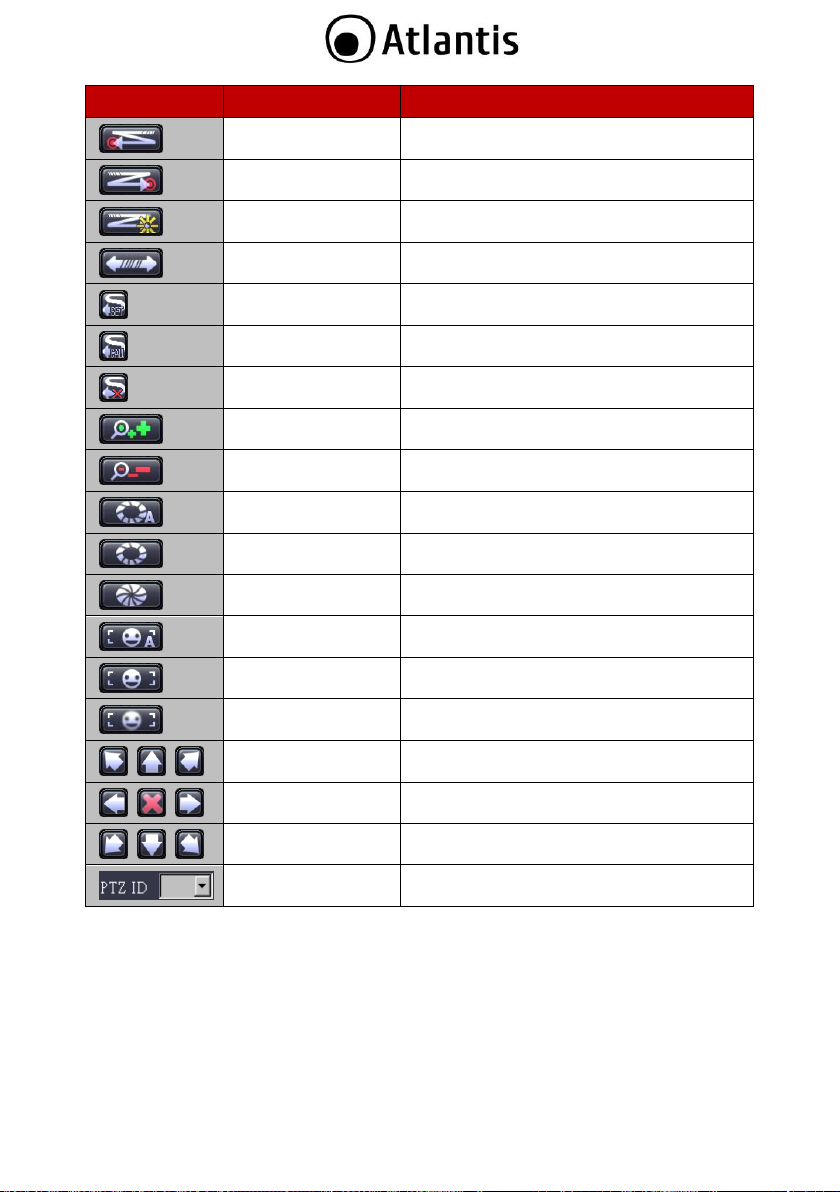
Icon
Name
Function
Left Limit
Set the left limit of auto pan
Right Limit
Set the right limit of auto pan
Patrol
Start / Stop the auto pan mode
Cruise
Start / Stop the cruise mode
Set
Set preset position
Call
Call preset position
Clear
Clear preset position
Zoom In
Tap the button to zoom in
Zoom Out
Tap the button to out
Auto Iris
Set as auto iris
Iris Open
Tap the button to make a selection
Iris Close
Tap the button to cancel a selection
Auto Focus
Set as auto focus
Focus Near
Tap the button to focus near
Focus Far
Tap the button to focus far
Directional Button
Move to top-left / top / top-right
Directional Button
Move to left / stop / right
Directional Button
Move to bottom-left / bottom / bottom-right
PTZ ID
Select the ID of the PTZ camera
77
Page 78

Control bar
Exit application
DVR configuration
Playback
4.4 Remote Playback
Click on the icon to display the remote playback interface on your PC Viewer. A selection window will
allow you to select between Time Search or Event Search.
78
Page 79

No.
Name
Function
1
Fast Backward 2x
Plays backward faster by twice the normal speed
2
Fast Backward 1x
Plays backward faster by 1x the normal speed
3
Playback
Starts the video playback
4
Fast Forward 1x
Plays forward faster by 1x the normal speed
5
Fast Forward 2x
Plays forward faster by twice the normal speed
6
Pause
Pauses the video playback
7
Stop
Stops the video playback
8
Time Bar
Adjust the playback time
9
Video Scroll Bar
Pans through a video as the button is moved
10
Volume
Volume switch
1 2 3 4 5 6 7 8 10
9
Preview of the Control Bar
Playback by Time Search
Time Search allows you to select the start time of the recording you would like to review in playback.
Select the “Begin Date” and “Begin Time”. Press the button “Play” to start video playback.
79
Page 80

While reviewing the video, you can click on the button to go back to the Time Search control
window.
Press the “Backup” button to create a copy of the video. The succeeding menu will require you to set
the following:
Path: Click on the “Browse” button to specify the location where you would like to store the file.
Begin: Select the start date and time for the video you would like to create a copy of.
End: Select the end date and time for the video you would like to create a copy of.
Channel: Select the channel or channels from which the backup video or videos will be taken
from.
Audio: Enables the inclusion of audio into the backup
Size: The file size automatically adjusts according to the duration (start and end time) set by
the user.
Press “Start” to begin the backup process.
80
Page 81

Playback by Event Search
Event Search allows you to specify a time. In the Event Search menu, you will be asked to set the following:
Event Begin Date: Select the start date for the video you would like to play back.
Event Begin Time: Select the start time for the video you would like to play back.
Event End Date: Select the end date for the video you would like to play back.
Event End Time: Select the start time for the video you would like to play back.
Event: Select the type of event you are searching for. The drop-down lists: Hardware, Normal,
Warning, Record, All
Press the button “Search” to start video playback.
You will see the search result table similar to the following figure:
81
Page 82

Double-click on the video you would like to review. While in the playback screen, you may click on the
Press the “Backup” button to create a copy of the video. The succeeding menu will require you to set
Path: Click on the “Browse” button to specify the location where you would like to store the file.
Begin: Select the start date and time for the video you would like to create a copy of.
End: Select the end date and time for the video you would like to create a copy of.
Channel: Select the channel or channels from which the backup video or videos will be taken from.
Audio: Enables the inclusion of audio into the backup
Size: The file size automatically adjusts according to the duration (start and end time) set by the user.
icon to access the Event Search control window.
the following:
Press “Start” to begin the backup process.
82
Page 83

4.5 Remote DVR Configuration
Click the icon to display the remote configuration interface on your PC Viewer.
Log-in to the Remote Configuration Interface
The authentication procedure for remote site access follows the DVR authentication process. Please login by
using the designated user name and password. If you did not change any of these settings on your DVR,
please use the default settings below.
Default User: admin
Default Password: 123456
You can change the DVR configuration after successfully logging in.
The operation method of the remote configuration interface is consistent with the DVR interface. Please
refer to the DVR operation sections on this manual.
PC Viewer Player
The PC Viewer can play stored PVF files with its built-in player.
Plug the USB device into USB port or transfer the file to a local disk on your personal computer from
the USB storage. Click on the “Player” tab on the PC Viewer interface.
83
Page 84

Click on “PlayFile” to locate the file you would like to view. Once the file is found, the PC Viewer Player will
automatically display the stored video.
84
Page 85

5. SUPPORT
For technical questions and support, please contact our help-desk by ticket on http://www.atlantis-
land.com/ita/supporto.php.
For generic informations, please send an e-mail to info@atlantis-land.com.
For presales informations, please send an e-mail to prevendite@atlantis-land.com.
Atlantis SpA
Via S. Antonio, 8/10
20020 Lainate (MI)
Italy
Fax: +39.02.78.62.64.39
Website: http://www.atlantis-land.com
Email: info@atlantis-land.com
85
Page 86

APPENDIX A: Dynamic DNS
Register with DynDNS
There are three suggested providers for DynDNS account: www.no-ip.com, www.changeip.com and
www.dyndns.com In the following example, we will use http://www.dyndns.com as the dynamic DNS
provider.
Create a DynDNS Account
Create a new account by filling out the spaces for Username, Password, and Email. Take note of your
user name and password. Be sure to use a valid email address.
86
Page 87

A verification mail will be sent to your registered email account.
Verify your account within 48 hours of receiving the e-mail.
Login and Host Service
Log-in by entering the Username and Password of your account.
Click on My Service to get a host name
87
Page 88

Double click on Add New Hostname to create a new host address.
Specify the host name for the DVR. You will use this name later to configure the DynDNS settings on
your DVR. Click on Add to Cart.
Press Next to proceed.
88
Page 89

Press Activate Services
Now, the DYNDNS service is completed. Take note of the Username, Password and Hostname.
89
Page 90

AVISO
Hemos hecho todo lo posible para evitar que en el texto, las imágenes, tablas, software y hardware, y la
información presentada en general sea carente de errores. A pesar de ello, no podemos garantizar la
ausencia de estos.
Atlantis Land no se hacen responsable de daños o pérdidas directas o indirectas, incluidos, pero sin
limitación, los daños causados por la imposibilidad su uso, la pérdida de datos o software y/o los daños o
pérdidas causados por el uso o funcionamiento incorrecto del equipo y accesorios. En ningún caso, Atlantis
Land será responsable de las pérdidas financieras como pérdida de beneficios, daños por inactividad, daños
a la reputación, etc.
El contenido de este manual se provee a título informativo y es sujeto a cambios sin previo aviso
(invitándose a los clientes a consultar nuestro sitio Web www.atlantis-land.com para mantenerse
informados de estos) no haciéndose Atlantis Land responsable de cualquier error o inexactitud que pueda
aparecer en esta guía.
Esta publicación no puede ser traducida ni reproducida, ni en todo ni en parte, ni registrada en, o
transmitida por, un sistema de recuperación de información, en ninguna forma ni por ningún medio, sea
mecánico, fotoquímico, electrónico, magnético, electrónico, por fotocopia, o cualquier otro, sin permiso
previo por escrito de Atlantis Land.
Los nombres de los fabricantes, de sus productos, así como de cualquier marca, registradas o no,
mencionadas en este manual, son usados a título de referencia, siendo propiedad exclusiva de sus
respectivos dueños.
Declaración de conformidad CE/EMC
El producto descrito en esta guía ha sido diseñado, producido y aprobado en conformidad con las reglas
EMC, siendo certificado en cumplimento de la normativa.
Si el producto se usara con un ordenador no certificado, el productor no puede garantizar el respeto a los
límites de compatibilidad electromagnética. En la práctica, y en circunstancias particulares, es posible que
dichos límites puedan ser superados si se utilizan dispositivos que no respetan la normativa EMC y que, por
tanto, no han sido certificados. Asimismo, es posible, que de forma puntual ocurran picos de valor que se
encuentran por encima de las tolerancias. En este caso, el usuario es responsable que el dispositivo vuelva
a ser conforme con los límites EMC. El fabricante no puede hacerse responsable en el caso de que el
producto sea utilizado fuera de los límites dictados por la normativa EMC.
Declaración de Conformidad
Este dispositivo ha sido probado, determinándose conforme con la directiva 2004/108/CE y Directive
2006/95/CE.
este aparato
El símbolo del contenedor de basura tachado sobre la etiqueta o envase indica que
este aparato no debe ser eliminado como residuo urbano no seleccionado sino que
debería ser recogido de modo selectivo.
Los residuos de aparatos eléctricos y electrónicos deben ser tratados de modo selectivo, en orden de
asegurar que los materiales peligrosos contenidos en los aparatos no sean quemados causando potenciales
problemas futuros para el medio ambiente y la salud humana. Por otro lado, será posible la reutilización y
reciclaje de algunas partes de los residuos de aparatos eléctricos y electrónicos, contribuyendo a reducir las
cantidades de residuos a eliminar y el agotamiento de los recursos naturales.
Información importante para el correcto procedimiento de reciclaje/tratamiento de
90
Page 91

Como usuario de esto aparato, usted es responsable de la devolución de este residuo de aparato electrónico
en la instalación de recogida oficial establecido por su Municipio. Para más información sobre las
instalaciones de recogida más próximas consulte en sus entidades locales.
Si usted reemplaza un antiguo aparato por un producto nuevo equivalente, el distribuidor deberá
recepcionar el antiguo de forma gratuita y uno por uno siempre
que este aparato sea de tipo equivalente y realice las mismas funciones que el aparato suministrado.
Su papel en la recogida selectiva de los residuos de aparatos eléctricos y electrónicos es esencial para
asegurar que los objetivos de protección del medio ambiente y de la salud humana, en conexión con un
tratamiento y reciclaje responsable, sean logrados.
PD: la información arriba mencionada ha sido redactada en concordancia con el RD 208/2005 de 25 de Febrero, el cual
establece la recogida separada y el diferente tratamiento y eliminación de los residuos de aparatos eléctricos y eléctronicos.
Para información adicional y en más detalle le invitamos a visitor nuestra página web www.atlantis-land.com
91
Page 92

El uso de dispositivos para captar imágenes, vídeo o voz podría estar reglamentado o
incluso prohibido en algunas jurisdicciones. Podría ser necesaria una autorización.
Atlantis SpA no garantiza de ningún modo que el uso de sus productos sea conforme a
las leyes locales y no puede asumir ninguna responsabilidad en caso de usos
inadecuados de los dispositivos.
Es oportuno señalizar claramente la presencia de dispositivos que captan imágenes,
vídeo o voz.
Respetar atentamente las leyes vigentes sobre las modalidades de conservación de los
contenidos de vídeo.
A09-TD410
A09-TD410
A09-TD410Kit
A09-TD410Kit-W
A09-TD810Kit
A09-TD810Kit-W
DVR (A09-TD410/A09-TD810)
4 Balun
Manual completo (italiano e inglés)
Ratón USB
DVR (A09-TD410)
4 cámaras infrarrojo
(A09-TT420-20-X)
4 soportes de montaje
DVR (A09-TD810)
4 cámaras infrarrojo
(A09-TT420-20-X)
4 soportes de montaje
Gracias por elegir un aparato de la familia NetDVR/NetCamera System, la solución más sencilla para la
videovigilancia. Este documento se divide en 2 partes. La primera parte (capítulo 1) es una guía rápida para
poner el sistema en funcionamiento rápidamente. Los capítulos siguientes explican el funcionamiento del
aparato detalladamente.
1. Descripción producida
NetCamera Ethernet System KIT
NetCamera Ethernet System KIT es una solucion completa (DVR y 4 Cameras con Led a rayos infrarrojos)
para enviar videos, hacer video vigilancia remota o para la transmision en tiempo real de
imagenes/ video. El Grabador digital (DVR) respalda 4/8 canales de video (alta compresion de tiempo real
H.264 ) con 1 conector VGA (y Video RCA). El sensor CCD (1/4”) permite trabajar en ambientes de poca luz,
dando imagenes de gran claridad y colores veraces, haciendola asi perfecta para la videovigilancia
(incorpora 28 IR LED para la vigilancia por la noche). NetCamera utiliza comunes cables
Ethernet por la conexion a las camaras (sobre el mismo cable viaja la alimentacion, la senal audio y video) y
tambien permite de migrar en futuro la infraestructura hacia IP, sin ulteriores costes
de cableado, salvaguardando la inversion hecha. Finalmente, tambien es importante resenar que toda la
funcionalidad con la que cuenta la Netcamera Ethernet System puede ser gestionada de
forma intuitiva usando tan solo el navegador, pudiendo acceder a ella desde cualquier sitio de forma remota
sin mas que una conexion a Internet (o intranet) incluso desde dispositivos moviles
3G (iPhone y iPad). NetCamera Ethernet System es la solucion ideal para enviar videos, hacer video
vigilancia remota.
NetDVR
El Grabador digital (NetDVR) respalda 4/8/16 canales de video (alta compresión de tiempo real H.264 ) con
1 conector VGA y Video RCA. NetDVR utiliza comúnes cables Ethernet por la conexión a las cámaras
(sobre el mismo cable viaja la alimentación, la señal audio y vídeo) y tambien permite de migrar en futuro
la infraestructura hacia IP, sin ulteriores costes de cableado, salvaguardando la inversión hecha. Finalmente,
también es importante reseñar que toda la funcionalidad con la que cuenta la NetDVR puede ser
gestionada de forma intuitiva usando tan solo el navegador, pudiendo acceder a ella desde cualquier sitio
de forma remota sin más que una conexión a Internet (o intranet) incluso desde dispositivos móviles 3G
(Android, iPhone y iPad). NetDVR es la solución ideal para enviar videos, hacer video vigilancia remota.
1.1 Requisitos de sistema (opcionales para acceso por WEB con IE)
Antes de instalar el producto comprobar que cumpla los siguientes requisitos:
1.2 CONTENIDO DEL ENVASE
Antes del uso comprobar que la caja contenga los siguientes elementos:
92
Page 93

Mando a distancia infrarrojo (pilas no
incluidas)
Alimentador AC-DC (12V@5A) con cable
de alimentación para alimentar el DVR y
Camaras
CD-rom que contiene el manual (en
italiano e inglés) y el software
Cupón de garantía
4 Balun
Manual completo (italiano
e inglés)
Ratón USB
Mando a distancia
infrarrojo (pilas no
incluidas)
Alimentador AC-DC
(12V@5A) con cable de
alimentación para
alimentar el DVR y
Camaras
CD-rom que contiene el
manual (en italiano e
inglés) y el software
Cupón de garantía
4 Balun
Manual completo (italiano
e inglés)
Ratón USB
Mando a distancia
infrarrojo (pilas no
incluidas)
Alimentador AC-DC
(12V@5A) con cable de
alimentación para
alimentar el DVR y
Camaras
CD-rom que contiene el
manual (en italiano e
inglés) y el software
Cupón de garantía
A09-TD1600
DVR (A09-TD1600)
4 Balun
Manual completo (italiano e inglés)
Ratón USB
Mando a distancia infrarrojo (pilas no incluidas)
Alimentador AC-DC (19V@6.3A) con cable de alimentación para alimentar el DVR y Camaras
CD-rom que contiene el manual (en italiano e inglés) y el software
Cupón de garantía
Si el contenido no corresponde, contactar con el revendedor inmediatamente.
1.3 INSTALACIÓN DEL DISCO EN EL DVR (A09-TD410)
Quitar los 4 tornillos de bloqueo del panel inferior y los 2 del panel posterior.
Retirar la tapa delicadamente.
Destornillar los 3 tornillos que bloquean el soporte para el disco.
Apoyar el disco en el soporte y atornillar los 4 tornillos de bloqueo.
Conectar los cables SATA/ALIMENTACIÓN al disco.
Colocar el soporte y atornillar los 3 tornillos de bloqueo.
Colocar la tapa y atornillar los 4 tornillos de bloqueo del panel inferior y los 2 del panel posterior. Para
más detalles ver la foto adjunta.
93
Page 94
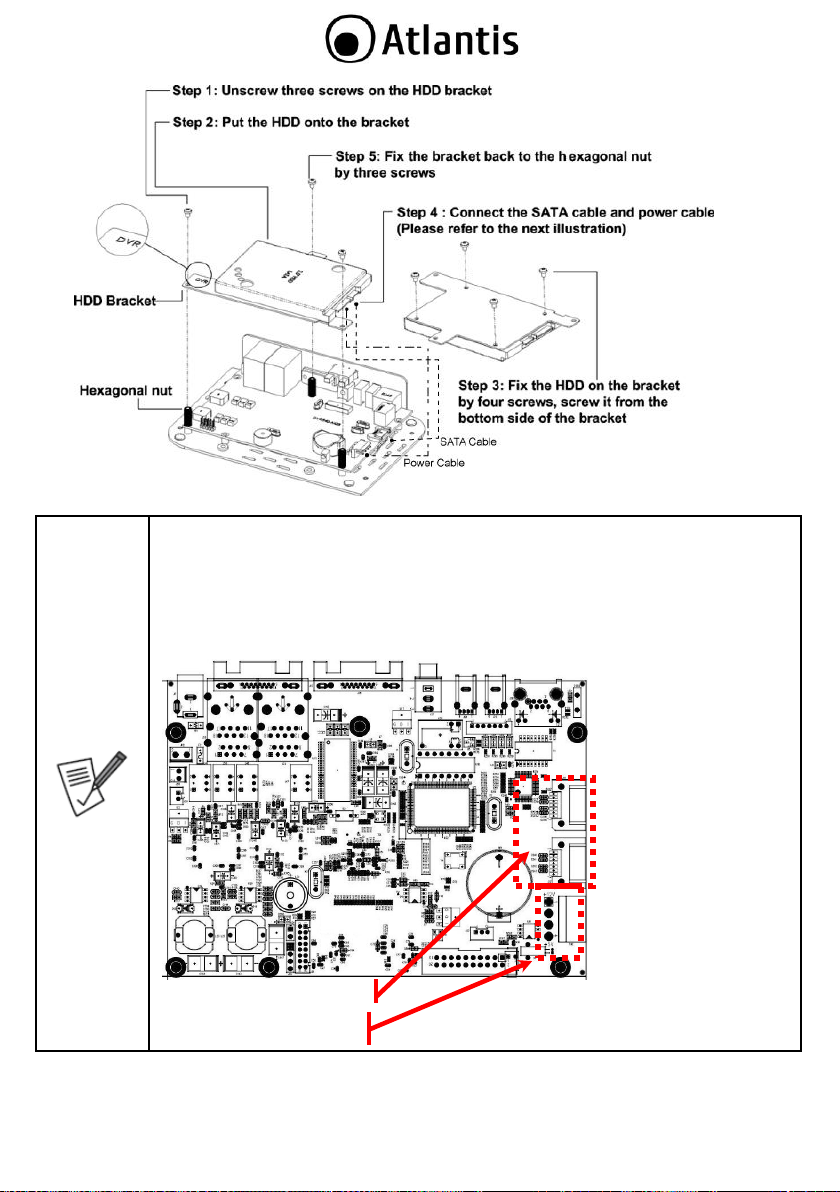
El disco se debe instalar con el sistema apagado y desconectado de la fuente de
alimentación.
En caso contrario, podría no funcionar correctamente. Consultar el apéndice B para
asegurarse de que el disco figure en la lista de compatibilidad.
Antes del cierre, asegurarse de que no queden elementos metálicos en el alojamiento.
En la figura siguiente se muestran los conectores del PCB donde conectar los cables
SATA (datos y potencia).
HDD Data
HDD Power Connector
94
Page 95

1.4 INSTALACIÓN DEL DISCO EN EL DVR (A09-TD810)
Aflojar los tornillos de bloqueo situados a los costados y en la parte posterior.
Retirar la tapa delicadamente, extrayéndola como indica la figura.
Conectar el cable de datos y el cable de alimentación al disco.
95
Page 96

El disco se debe instalar con el sistema apagado y desconectado de la fuente de
alimentación.
En caso contrario, podría no funcionar correctamente. Consultar el apéndice B para
asegurarse de que el disco figure en la lista de compatibilidad
Instalar el disco en el soporte y fijarlo firmemente con los tornillos.
Comprobar que los conectores estén conectados correctamente, cerrar la tapa y atornillar nuevamente
los tornillos.
1.5 MONTAJE DE LA CÁMARA
NetCamera Ethernet System se suministra con un KIT para el montaje de las cámaras en la pared y/o en el
escritorio. Utilizar 3 tornillos/clavos (se suministran 3 tornillos con los soportes de pared) para fijar la base
en una superficie plana (pared o techo). Atornillar la base en la parte posterior/inferior de la cámara. Por
último, colocarla en la posición correcta (apretando el tornillo).
96
Page 97

No colocar la NetCamera en ambientes exteriores o donde quede expuesta a fenómenos
atmosféricos.
Asegurarse de que el pedestal quede firmemente anclado en la pared (para evitar que
NetCamera se caiga).
La óptica no debe quedar expuesta a la irradiación solar directa.
El incumplimiento de las condiciones enunciadas podría implicar daños para el aparato y
podría dejar la garantía sin efecto.
Conectar la salida de vídeo y la entrada de potencia de la cámara al Balun y éste, por medio del cable
Ethernet, al DVR (en una de las 4 entradas CH IN).
1.6 CABLEADO DE LA CÁMARA
El esquema siguiente proporciona instrucciones claras para el cableado de las 4 cámaras infrarrojo
utilizando los Balun suministrados. El cable de conexión entre el Balun y el DVR es un cable de red CAT5
normal de 8 conductores (utilizar una conexión directa, hasta 100m).
97
Page 98

Para conectar las cámaras:
Conectar el cable BNC/Alimentación BALUN a la cámara.
Conectar el cable RC del BALUN a un micrófono (opción).
Conectar al BALUN el extremo de un cable Ethernet (CAT 5E), y conectar el otro
extremo al DVR (CH1,CH2,CH3 o CH4 o CH8).
Repetir el mismo procedimiento con todas las cámaras.
Los cables Ethernet no están incluidos en el envase.
N°
FUNCIÓN
SIGNIFICADO
1
Puerto Ethernet
Utilizar este puerto Ethernet (interfaz RJ45) para conectar el
dispositivo a la LAN.
1.7 CABLEADO DVR(A09-TD410)
En la figura es posible observar el panel posterior del dispositivo.
98
Page 99

2
Puerto USB
Utilizar este puerto USB para conectar un periférico de memorización
externo (disco o tarjeta de memoria) para la copia de seguridad de los
datos o la actualización del firmware. Es posible la
conexión/desconexión en caliente.
3
Puerto USB
Conectar el ratón suministrado.
4
IR Extender
N/A
5
Salida/Entrada
audio
Salida/Entrada audio (interfaz RCA).
6
Salida VGA/RCA
Conectar a una pantalla externa (interfaz VGA). La resolución máxima
posible es 1280x1024 píxeles.
Conectar a una pantalla externa (interfaz RCA)
7
Entrada vídeo
(RJ45)
Utilizar cables Ethernet CAT5 para conectar las cámaras por medio de
los BALUN suministrados.
8
Toma de
alimentación
Conectar la toma de alimentación. Utilizar sólo el alimentador
suministrado. Las características del dispositivo son: DC, 12V@5A.
1
7
2 3 4 5 6 8 9
10
11
12 1 7 2 3 4 5 6 8
9
10
11
12 5 4 8 12
Conectar al DVR (donde se ha puesto el disco) en el siguiente orden:
Los cables CAT5 provenientes de los Balun conectados a las 4 cámaras (Cable Ethernet, referencia
sección 1.6)
el ratón suministrado al DVR
el cable VGA a un monitor
el cable de red para la conexión al switch/router (opción)
altavoz (opción)
cable de alimentación
1.8 CABLEADO DVR (A09-TD810/A09-TD1600)
En la figura es posible observar el panel posterior del dispositivo.
99
Page 100

N°
FUNCIÓN
SIGNIFICADO
1
Puerto Ethernet
Utilizar este puerto Ethernet (interfaz RJ45) para conectar el
dispositivo a la LAN.
2
Puerto USB
Utilizar este puerto USB para conectar un periférico de memorización
externo (disco o tarjeta de memoria) para la copia de seguridad de los
datos o la actualización del firmware. Es posible la
conexión/desconexión en caliente.
3
Puerto USB
Conectar el ratón suministrado.
4
Salida VGA
Conectar a una pantalla externa (interfaz VGA). La resolución máxima
posible es 1280x1024 píxeles.
5
Salida Video
Conectar a una pantalla externa (interfaz RCA)
6
Salida audio
Salida audio (interfaz RCA).
7
Entrada audio
Entrada audio (interfaz RCA).
8
Entrada vídeo
(RJ45)
Utilizar cables Ethernet CAT5 para conectar las cámaras por medio de
los BALUN suministrados.
9
Toma de
alimentación
Conectar la toma de alimentación. Utilizar sólo el alimentador
suministrado. Las características del dispositivo son: DC,
12V@5A/19V@6.3A.
10
PTZ(RS485)
Conectar a una cámaras externa (interfaz RS485)
11
Allarm
Conectar a una sirena externa
12
Sensor
Conectar hasta a 4/16 sensoriales exteriores por el hilo (G es en
común).
Conectar al DVR (donde se ha puesto el disco) en el siguiente orden:
Los cables CAT5 provenientes de los Balun conectados a las 4 cámaras (Cable Ethernet, referencia
sección 1.6)
el ratón suministrado al DVR
el cable VGA a un monitor
el cable de red para la conexión al switch/router (opción)
altavoz (opción)
cable de alimentación
100
 Loading...