

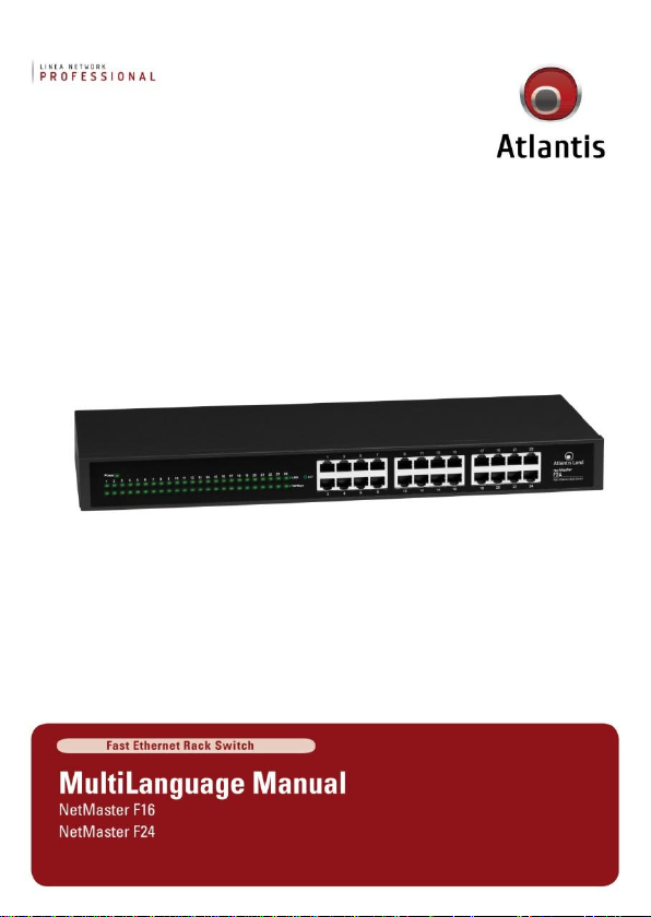
Page 1
Page 2
ITALIANO
Questo prodotto è coperto da garanzia Atlantis della durata di 2 anni. Per maggiori
dettagli in merito o per accedere alla documentazione completa in Italiano fare
riferimento al sito www.atlantis-land.com.
ENGLISH
This product is covered by Atlantis 2 years warranty. For more detailed informations
please refer to the web site www.atlantis-land.com.
For more detailed instructions on configuring and using this device, please refer to
the online manual.
FRANCAIS
Ce produit est couvert par une garantie Atlantis de 2 ans. Pour des informations
plus détaillées, référez-vous svp au site Web www.atlantis-land.com.
DEUTSCH
Dieses Produkt ist durch die Atlantis 2 Jahre Garantie gedeckt. Für weitere
Informationen, beziehen Sie sich bitte auf Web Site www.atlantis-land.com.
ESPAÑOL
Este producto esta cubierto por Atlantis con una garantía de 2 años. Para mayor
información diríjase a nuestro sitio Web www.atlantis-land.com.
Page 3

ITALIANO
1. Panoramica Generale .......................................................................... 9
1.1 Tecnologia Fast Ethernet .............................................................. 9
1.2 Tecnologia Switching ................................................................... 9
2. Caratteristiche ................................................................................... 10
3. Installazione ...................................................................................... 11
3.1 Contenuto della Confezione ......................................................... 11
3.2 Setup 11
3.3 Schema Applicativo ..................................................................... 12
3.4 Installazione su Rack .................................................................. 12
3.5 Pannello Frontale ........................................................................ 13
4. Supporto Offerto ............................................................................... 14
ENGLISH
1. Introduction ...................................................................................... 18
1.1 Fast Ethernet Technology ............................................................ 18
1.2 Switching Technology ................................................................. 18
2. Features ........................................................................................... 19
3. Unpacking and Setup ......................................................................... 21
3.1 Package Contents ....................................................................... 21
3.2 Installation ................................................................................. 21
3.3 Application Scheme .................................................................... 22
3.4 Rack Mounting ........................................................................... 22
3.5 Front Panel ................................................................................ 23
4. Support ............................................................................................ 24
FRANCAIS
1. Introduction ...................................................................................... 27
1.1 Fast Ethernet ............................................................................. 27
1.2 Tecnologia Switching .................................................................. 27
2. Principales caractéristiques ................................................................ 27
3. Installation ........................................................................................ 29
3.1 Contenu de la boîte .................................................................... 29
3.2 Setup 29
3.3 Example de Réseaux ................................................................... 30
3.4 Installation en Rack .................................................................... 30
3
Page 4

3.5 Panneau Avant ........................................................................... 31
4. Support ............................................................................................ 32
APPENDIX
APPENDIX A: Technical Features ......................................................................... 33
A02-F16(24)_MX01 (v1.5 May 2010)
4
Page 5

AVVERTENZE
Abbiamo fatto di tutto al fine di evitare che nel testo, nelle immagini e nelle tabelle
presenti in questo manuale, nel software e nell'hardware fossero presenti degli
errori. Tuttavia, non possiamo garantire che non siano presenti errori e/o omissioni.
Infine, non possiamo essere ritenuti responsabili per qualsiasi perdita, danno o
incomprensione compiuti direttamente o indirettamente, come risulta dall'utilizzo del
manuale, software e/o hardware.
Il contenuto di questo manuale è fornito esclusivamente per uso informale, è
soggetto a cambiamenti senza preavviso (a tal fine si invita a consultare il sito
www.atlantisland.it o www.atlantis-land.com per reperirne gli aggiornamenti) e non
deve essere interpretato come un impegno da parte di Atlantis che non si assume
responsabilità per qualsiasi errore o inesattezza che possa apparire in questo
manuale. Nessuna parte di questa pubblicazione può essere riprodotta o trasmessa
in altra forma o con qualsiasi mezzo, elettronicamente o meccanicamente,
comprese fotocopie, riproduzioni, o registrazioni in un sistema di salvataggio,
oppure tradotti in altra lingua e in altra forma senza un espresso permesso scritto
da parte di Atlantis. Tutti i nomi di produttori e dei prodotti e qualsiasi marchio,
registrato o meno, menzionati in questo manuale sono usati al solo scopo
identificativo e rimangono proprietà esclusiva dei loro rispettivi proprietari.
Restrizioni di responsabilità CE/EMC
Il prodotto descritto in questa guida è stato progettato, prodotto e approvato in
conformità alle regole EMC ed è stato certificato per non avere limitazioni EMC.
Se il prodotto fosse utilizzato con un PC/apparati non certificati, il produttore non
garantisce il rispetto dei limiti EMC. Il prodotto descritto è stato costruito, prodotto
e certificato in modo che i valori misurati rientrino nelle limitazioni EMC. In pratica,
ed in particolari circostanze, potrebbe essere possibile che detti limiti possano
essere superati se utilizzato con apparecchiature non prodotte nel rispetto della
certificazione EMC. Può anche essere possibile, in alcuni casi, che i picchi di valore
siano al di fuori delle tolleranze. In questo caso l‟utilizzatore è responsabile della
“compliance” con i limiti EMC. Il Produttore non è da ritenersi responsabile nel caso
il prodotto sia utilizzato al di fuori delle limitazioni EMC.
CE Mark Warning
In un ambiente domestico il dispositivo può causare interferenze radio, in questo
caso è opportuno prendere le adeguate contromisure.
5
Page 6
Dichiarazione di Conformità
Con la presente dichiaramo che questo apparato (A02-F16 e A02-F24) soddisfa
tutti i requisiti applicabili alla tipologia del prodotto e richiesti dalla
regolamentazione delle telecomunicazioni secondo direttiva 2004/108/CE
(compatibilità elettromagnetica) e 2006/95/CE (sicurezza elettrica) tramite l‟utilizzo
delle norme pubblicate nella gazzetta ufficiale della comunità Europea. La
dichiarazione di conformità nella sua forma completa è disponibile presso il sito
www.atlantis-land.com (alla pagina del prodotto) o può essere richiesta a
info@atlantis-land.com.
riciclaggio/smaltimento di questa apparecchiatura
Importanti informazioni per il corretto
Il simbolo qui sotto indicato, riportato sull'apparecchiatura elettronica da Lei
acquistata e/o sulla sua confezione, indica che questa apparecchiatura elettronica
non potrà essere smaltita come un rifiuto qualunque ma dovrà essere oggetto di
raccolta separata.
Infatti i rifiuti di apparecchiatura elettroniche ed elettroniche devono essere
sottoposti ad uno specifico trattamento, indispensabile per evitare la dispersione
degli inquinanti contenuti all''interno delle apparecchiature stesse, a tutela
dell'ambiente e della salute umana. Inoltre sarà possibile riutilizzare/riciclare parte
dei materiali di cui i rifiuti di apparecchiature elettriche ed elettroniche sono
composti, riducendo così l'utilizzo di risorse naturali nonché la quantità di rifiuti da
smaltire.
Atlantis, in qualità di produttore di questa apparecchiatura, è impegnato nel
finanziamento e nella gestione di attività di trattamento e recupero dei rifiuti di
apparecchiature elettriche ed elettroniche compatibili con l'ambiente e con la salute
umana.
E' Sua responsabilità, come utilizzatore di questa apparecchiatura elettronica,
provvedere al conferimento della stessa al centro di raccolta di rifiuti di
apparecchiature elettriche ed elettroniche predisposto dal Suo Comune. Per
6
Page 7
Tutte le condizioni di utilizzo, avvertenze e clausole
contenute in questo manuale e nella garanzia si intendono
note ed accettate. Si prega di restituire immediatamente
(entro 7 giorni dall‟acquisto) il prodotto qualora queste non
siano accettate.
La marcatura CE e/o il simbolo di attention Mark (
) poste sull‟etichetta di prodotto potrebbero
non rispettare le dimensioni minime stabilite dalla
normativa a causa delle ridotte dimensioni di quest‟ultima.
maggiori informazioni sul centro di raccolta a Lei più vicino, La invitiamo a
contattare i competenti uffici del Suo Comune.
Qualora invece avesse deciso di acquistare una nuova apparecchiata elettronica di
tipo equivalente e destinata a svolgere le stesse funzioni di quella da smaltire, potrà
portare la vecchia apparecchiatura al distributore presso cui acquista la nuova. Il
distributore sarà tenuto ritirare gratuitamente la vecchia apparecchiatura1.
Si tenga presente che l'abbandono ed il deposito incontrollato di rifiuti sono puniti
con sanzione amministrativa pecuniaria da € 103 a € 619, salvo che il fatto
costituisca più grave reato. Se l'abbandono riguarda rifiuti non pericolosi od
ingombranti si applica la sanzione amministrativa pecuniaria da € 25 a € 154.
Il suo contributo nella raccolta differenziata dei rifiuti di apparecchiature elettriche
ed elettroniche è essenziale per il raggiungimento di tutela della salute umana
connessi al corretto smaltimento e recupero delle apparecchiature stesse.
1 Il distributore non sarà tenuto a ritirare l'apparecchiatura elettronica qualora vi sia un rischio di
contaminazione del personale incaricati o qualora risulti evidente che l'apparecchiatura in
questione non contiene i suoi componenti essenziali o contiene rifiuti diversi da apparecchiature
elettriche e/o elettroniche.
NB: le informazioni sopra riportate sono redatte in conformità alla Direttiva 2002/96/CE ed al D.
nonché particolari modalità di trattamento e smaltimento dei rifiuti di apparecchiature elettriche
ed elettroniche (RAEE). Per ulteriori informazioni in materia, la invitiamo a consultare il nostro sito
www.atlantis-land.com
7
Page 8
Atlantis invita a visitare il sito web www.atlantis-land.com
alla relativa pagina di prodotto per reperire manualistica e
contenuti tecnici (aggiornamenti driver e/o funzionalità,
utility, support note) aggiornati.
Il logo WEEE ( ) posto sull‟etichetta di prodotto
potrebbe non rispettare le dimensioni minime stabilite dalla
normativa a causa delle ridotte dimensioni di quest‟ultima.
Per usufruire delle condizioni di garanzia
migliorative associate al prodotto (Fast Swap, On
Site e On Center) è opportuno provvedere alla
registrazione dello stesso sul sito www.atlantisland.com entro e non oltre 15 giorni dalla data di
acquisto. La mancata registrazione entro il termine
di sopra farà si che il prodotto sia coperto
esclusivamente dalla condizioni standard di
garanzia.
8
Page 9

La ringraziamo per aver scelto un apparato Atlantis. Si consiglia la lettura di questo
documento al fine di un corretto utilizzo del prodotto.
1. Panoramica Generale
Questo capitolo descrive le caratteristiche proprie dello Switch e fornisce alcune
informazioni di carattere generale sulla tecnologia di switch Ethernet/Fast Ethernet.
1.1 Tecnologia Fast Ethernet
Il continuo aumento di importanza della LAN e l‟incremento della complessità delle
applicazioni che girano sui normali PC ha portato alla necessità di avere strutture
che fornissero delle performance sempre crescenti. Un notevole numero di
tecnologie diverse per LAN ad alta velocità ha visto la luce proprio per rispondere a
queste esigenze. La soluzione che si è imposta (la 100BASE-T) risponde a queste
rinnovate esigenze pur avendo un approccio non distruttivo con l‟installato.
Nelle specifiche IEEE 802.3 LAN sono contenute tutte le caratteristiche del 100Mbs
Fast Ethernet. Questa è un‟estensione del precedente standard a 10Mbs cui
aggiunge la capacità di trasmissione dieci volte maggiore, pur mantenendo il
protocollo CSMA/CD. Questo consente agli apparati conformi alla Fast Ethernet di
essere utilizzati anche in modalità Ethernet, consentendo un riutilizzo di apparati e
una migrazione graduale alla nuova tecnologia.
1.2 Tecnologia Switching
Lo switching è una strada che rende possibile da un lato l‟aumento della capacità
(numero di utenti collegati) di una rete e dall‟altra la diminuzione del carico
suddividendo la LAN in diversi segmenti. Solo i segmenti opportuni sono interessati
al contrario dell‟hub che replica il traffico su tutti i segmenti.
Lo switch attua una sorta di bridge selettivo tra segmenti individuali. Lo switch
infatti, senza interferire con altri segmenti, automaticamente instrada il traffico da
un segmento ad un altro. In questa maniera la capacità della LAN cresce
notevolmente, pur non dovendone cambiare l‟hardware presente.
La tecnologia Switching LAN è un deciso miglioramento rispetto alla precedente
generazione dei network bridges caratterizzati da un‟alta latenza. Questo problema
può essere risolto anche facendo uso di Router che segmentano la LAN ma il costo
di questa tecnologia notevolmente superiore unito alla necessità di un continuo
controllo rende questo approccio quasi impraticabile. Oggi lo switch rappresenta la
soluzione ideale per risolvere i problemi di congestione nella maggior parte delle
LAN.
9
Page 10

2. Caratteristiche
Lo Switch 16(24) porte 10/100 Mbps Fast Ethernet è stato disegnato per essere
facilmente installato ed offrire alte performance in un ambiente dove il traffico della
rete ed il numero di utenti sono in continuo aumento. Lo Switch è espandibile
collegandolo ad altri in cascata tramite una qualsiasi porta (consente il
trasferimento di 200Mbps). Grazie a questa caratteristica potrete pensare ad
ulteriori espansioni graduali della Lan riutilizzando al massimo gli investimenti fatti.
Lo Switch combina un‟allocazione dinamica della memoria e assieme alla tecnologia
di switching store-and-forwarding assicura (controllando il flusso di dati tra il
trasmittente ed il ricevente) un miglioramento delle prestazioni (diminuendo il
numero di pacchetti persi). Vediamo le caratteristiche chiave dello Switch:
16(24) porte 10/100 Base Ethernet con connettore RJ45
Supporta autonegoziazione su ogni porta
Auto MDI/MDI-X per ogni porta
Wire speed in recezione e trasmissione
Supporta Store-and-Forward switching method
Supporta sino ad 8K indirizzi MAC
Broadcast storm protection
Supporta 1,25Mb (2,5Mb nel A02-F24) RAM per buffering dei dati
Esaustivo front-panel con LED per la diagnostica
Supporta controllo di flusso (IEEE 802.3x ) in full-duplex
Supporta Back pressure in modalità half-duplex
Fornito di staffe per il montaggi su 19” standard rack
10
Page 11

3. Installazione
Questo capitolo fornisce informazioni per l‟installazione e la configurazione dello
Switch. Per evitare possibili cause di danneggiamento è opportuno leggere
attentamente l‟intero paragrafo prima di partire.
3.1 Contenuto della Confezione
Una volta aperta la confezione in cartone dovrebbero essere presenti:
16/24 porte 10/100Mbps Fast Ethernet Switch
Cavo di alimentazione
Supporti in gomma per il montaggio desktop
Kit di installazione per strutture rack 19”
Guida Utente (Italiano, Inglese e Francese)
Qualora mancasse uno qualsiasi di questi componenti è opportuno rivolgersi
immediatamente al rivenditore.
3.2 Setup
La fase di setup dello Switch prevede i seguenti steps:
La presa elettrica deve essere entro 1.82 metri dall‟apparecchio.
Assicurarsi che la presa del cavo di alimentazione sia collegata
propriamente al connettore AC posto sul pannello posteriore
dell‟apparecchio.
Accertarsi che sia posto in un ambiente con un‟adeguata ventilazione,
non esposto a raggi solari, in un ambiente privo di vibrazioni e in
assenza di forti campi elettromagnetici (tipicamente creati da motori
elettrici).
Controllare inoltre le condizioni di temperatura ed umidità (facendo
riferimento alla tabella Caratteristiche Fisiche ed Ambientali).
11
Page 12

3.3 Schema Applicativo
3.4 Installazione su Rack
Lo Switch Ethernet può essere montato in un EIA di dimensioni standard, 19-inch
rack, cui può essere fissato grazie alle staffe fornite. E‟ necessario anzitutto
collegare le braccia (una per lato) allo Switch con le apposite viti.
A questo punto utilizzare le ulteriori viti fornite per fissare le braccia alla struttura
metallica e fissare così saldamente lo Switch.
12
Page 13

LED
SIGNIFICATO
Power
Se acceso indica una corretta alimentazione.
Link/Activity
Se Acceso indica il Link attivo, se lampeggiante indica
trasmissione o ricezione dati.
100 Mbps
Se acceso indica un Link funzionante a 100Mbps, se
lampeggia indica trasferimento di dati sulla porta. Se
spento (ed il corrispondente Link è acceso) indica una
velocità di 10Mbps.
3.5 Pannello Frontale
Nel panello frontale dello Switch sono presenti 16(24) porte 10/100 Fast Ethernet e
tutta una serie di led per una diagnostica immediata. Gli indicatori presenti nel
pannello frontale dello switch sono:
13
Page 14

Tutte le porte sono con autopolarità, pertanto funzioneranno
(aggiustando la polarità) indipendentemente dal cavo utilizzato
(sia questo dritto o incrociato). Potrete collegare ogni porte
indipendentemente dal cavo sia ad una scheda di rete che ad
un hub/switch.
4. Supporto Offerto
Per qualunque altro problema o dubbio sul funzionamento del prodotto, è possibile
contattare il servizio di assistenza tecnica Atlantis tramite l‟apertura di un ticket on-
line sul portale http://www.atlantis-land.com/ita/supporto.php.
Nel caso non fosse possibile l‟accesso al portale di supporto, è altresì possibile
richiedere assistenza telefonica al numero 02/ 78.62.64.37 (consultare il sito per
verificare gli orari in cui il servizio viene erogato).
Per esporre eventuali richieste di supporto prevendita o richieste di contatto , si
invita ad utilizzare gli indirizzi mail info@atlantis-land.com oppure
prevendite@atlantis-land.com.
Atlantis SpA
Via S. Antonio, 8/10
20020 Lainate (MI)
Fax: +39.02.78.62.64.39
Website: http://www.atlantis-land.com
Email: info@atlantis-land.com
14
Page 15

Copyright Statement
No part of this publication may be reproduced, stored in a retrieval system, or
transmitted in any form or by any means, whether electronic, mechanical,
photocopying, recording or otherwise without the prior writing of the publisher.
Windows™ 98SE/2000/ME/XP/VISTA are trademarks of Microsoft® Corp. Pentium is
trademark of Intel. All copyright reserved.
The Atlantis logo is a registered trademark of Atlantis. All other names mentioned
mat be trademarks or registered trademarks of their respective owners. Subject to
change without notice. No liability for technical errors and/or omissions.
Regulatory Information/disclaimers
Installation and use of this Wireless LAN device must be in strict accordance with
the instructions included in the user documentation provided with the product. Any
changes or modifications made to this device that are not expressly approved by
the manufacturer may void the user‟s authority to operate the equipment. The
Manufacturer is not responsible for any radio or television interference caused by
unauthorized modification of this device, of the substitution or attachment.
Manufacturer and its authorized resellers or distributors will assume no liability for
any damage or violation of government regulations arising from failing to comply
with these guidelines.
CE Mark Warning
In a domestic environment, this product may cause radio interference, in which
case the user may be required to take adequate measures.
CE/EMC Restriction of Liability
The product described in this handbook was designed, produced and approved
according to the EMC-regulations and is certified to be within EMC limitations.
If the product is used in an uncertified PC, the manufacturer undertakes no
warranty in respect to the EMC limits. The described product in this handbook was
constructed, produced and certified so that the measured values are within EMC
limitations. In practice and under special circumstances, it may be possible, that
the product may be outside of the given limits if it is used in a PC that is not
produced under EMC certification. It is also possible in certain cases and under
special circumstances, which the given EMC peak values will become out of
tolerance. In these cases, the user himself is responsible for compliance with the
EMC limits.
15
Page 16

Declaration of Conformity
Hereby We declare that this product (A02-F16 and A02-F24) is in compliance to all
relevant essential requirements of the Electromagnetic Compatibility Directive
(2004/108/CE) and Safety (2006/95/CE). CE Declaration is available on the web site
www.atlantis-land.com.
procedures of this equipment
The crossed-out wheeled bin symbol printed on the unit label or unit packaging
indicates that this equipment must not be disposed of as unsorted municipal waste
but it should be collected separately.
The waste of electric and electronic equipment must be treated separately, in order
to ensure that hazardous materials contained inside the equipment are not buried
thereby providing potential future problems for the environment and human health.
Moreover, it will be possible to reuse and recycle some parts of the waste of electric
and electronic equipment, contributing to reduce the quantities of waste to be
disposed of and the depletion of natural resources.
As user of this equipment, you are responsible to return this waste of electronic
equipment to an authorised collection facility set up by your Municipality. More
detailed information on your nearest collection centre can be obtained from your
Municipality or from other competent local entities.
If you are replacing the old equipment with a new equivalent product, the
distributor must take-back the old equipment free of charge on a one-to one basis
as long as the equipment is of equivalent type and fulfilled the same functions as
the supplied equipment.
Your rôle in participating to the separate collection of waste of electric and
electronic equipment is essential to ensure that environmental protection and
human health objectives connected to a responsible treatment and recycling
activities are achieved.
PS.: The above mentioned information are reported herewith in compliance with Directive
2002/96/CE, which requires a separate collection system and specific treatment and disposal
procedures for the waste of electric and electronic equipments (WEEE). For further and more
detailed information, we invite you to visit our website at www.atlantis-land.com
Important information for the correct recycle/treatment
16
Page 17

CE Logo with attention Mark ( ) aren‟t fully
compliant with minimum dimensions requirement to
European Directive due to limited sticker area.
WEEE BIN Logo ( ) isn‟t fully compliant with
minimum dimensions requirement to European Directive
due to limited sticker area.
Atlantis suggest to vistit the web site www.atlantis-
land.com in order to retrieve update manual, techsheet
and driver.
Before starting, take a few minutes to read this manual.
Read all of instructions and save this manual for later
reference.
17
Page 18

Congratulations on your purchase of the 16-port 10/100Mbps Auto-negotiation Fast
Ethernet Switch. This device integrates 100Mbps Fast Ethernet and 10Mbps
Ethernet network capabilities in a highly flexible package.
1. Introduction
This chapter describes the features of the Switch and some background information
about Ethernet/Fast Ethernet switching technology.
1.1 Fast Ethernet Technology
The growing importance of LANs and the increasing complexity of desktop
computing applications are fueling the need for high performance networks. A
number of high-speed LAN technologies have been proposed to provide greater
bandwidth and improve client/server response times. Among them, 100BASE-T
(Fast Ethernet) provides a non-disruptive, smooth evolution from the current
10BASE-T technology. The non-disruptive and smooth evolution nature, and the
dominating potential market base, virtually guarantee cost effective and high
performance Fast Ethernet solutions in the years to come.
100Mbps Fast Ethernet is a new standard specified by the IEEE 802.3 LAN
committee. It is an extension of the 10Mbps Ethernet standard with the ability to
transmit and receive data at 100Mbps, while maintaining the CSMA/CD Ethernet
protocol. Since the 100Mbps Fast Ethernet is compatible with all other 10Mbps
Ethernet environments, it provides a straightforward upgrade and takes advantage
of the existing investment in hardware, software, and personnel training.
1.2 Switching Technology
Another key development pushing the limits of Ethernet technology is in the field of
switching technology. A switch bridges Ethernet packets at the MAC address level of
the Ethernet protocol transmitting among connected Ethernet or fast Ethernet LAN
segments.
Switching is a cost-effective way of increasing the total network capacity available
to users on a local area network. A switch increases capacity and decreases
network loading by making it possible for a local area network to be divided into
different segments which don‟t compete with each other for network transmission
capacity, giving a decreased load on each.
The switch acts as a high-speed selective bridge between the individual segments.
Traffic that needs to go from one segment to another is automatically forwarded by
the switch, without interfering with any other segments. This allows the total
network capacity to be multiplied, while still maintaining the same network cabling
and adapter cards.
18
Page 19

Switching LAN technology is a marked improvement over the previous generation of
network bridges, which were characterized by higher latencies. Routers have also
been used to segment local area networks, but the cost of a router and the setup
and maintenance required make routers relatively impractical. Today‟s switches are
an ideal solution to most kinds of local area network congestion problems.
2. Features
The Switch were designed for easy installation and high performance in an
environment where traffic on the network and the number of user increase
continuously.
The Switch with its rack size is specifically designed for middle to large workgroups.
The Switch provides immediate access to a rapidly growing network through a wide
range of user-reliable functions.
The Switch is ideal for deployment with multiple high-speed servers for shared
bandwidth 10Mbps or 100Mbps workgroups. With the highest bandwidth 200Mbps
(100Mbps full-duplex mode), any port can provide workstations with a congestionfree data pipe for simultaneous access to the server.
The Switch is expandable by cascading two or more switches together. As all ports
support 200Mbps, the Switch can be cascaded from any port and to any number of
switches.
The Switch is a perfect choice for site planning to upgrade to Fast Ethernet in the
future. Ethernet workgroups can connect to the Switch now, and change adapters
and hubs anytime later without needing to change the Switch or reconfigure the
network.
The Switch combine dynamic memory allocation with store-and-forward switching
to ensure that the buffer is effectively allocated for each port, while controlling the
data flow between the transmit and receive nodes to guarantee against all possible
packet loss.
The Switch is an unmanaged 10/100 Fast Ethernet Switch that offers solutions in
accelerating small Ethernet workgroup bandwidth. Other key features are:
16-port 10/100BASE Ethernet Switch with RJ-45 connectors
Support Auto-negotiation for speed and duplex modes for each port
Supports Auto-MDI/MDI-X for each port
Wire speed reception and transmission
Store-and-Forward switching method
19
Page 20

Integrated address Look-Up Engine, supports 8K absolute MAC
addresses
Supports 1.25Mbits (2,5Mbit for A02-F24) RAM for data buffering
Front-panel diagnostic LEDs
IEEE 802.3x flow control for full-duplex
Back pressure flow control for half-duplex
Standard 19” Rack-mountable size
20
Page 21

3. Unpacking and Setup
This chapter provides unpacking and setup information for the Switch.
3.1 Package Contents
Unpack the package and check all the items carefully. If any item contained is
damaged or missing, please contact your local dealer as soon as possible. Also,
keep the box and packing materials in case you need to ship the unit in the future.
The package should contain the following items:
One NetMaster F16/24 Switch
One power cord
Rubber footpads for Desk-mount
Rack-mount kit for installing the switch in a 19-inch rack
One Quick Start Guide (English, Italian and French)
3.2 Installation
The site where you install the Switch stack may greatly affect its performance.
When installing, consider the following pointers:
Install the Switch in a fairly cool and dry place. See Specifications for
the acceptable temperature and humidity operating ranges.
Install the Switch in a site free from strong electromagnetic field
generators (such as motors), vibration, dust, and direct exposure to
sunlight.
Leave at least 10cm of space at the front and rear of the hub for
ventilation.
Install the Switch on a sturdy, level surface that can support its weight,
or in an EIA standard-size equipment rack.
(For information on rack installation, see the next section Rack
Mounting).
When installing the Switch on a level surface, attach the rubber feet to
the bottom of each device. The rubber feet cushion the hub and
protect the hub case from scratching.
21
Page 22

3.3 Application Scheme
3.4 Rack Mounting
The switch can be mounted in an EIA standard-size, 19-inch rack, which can be
placed in a wiring closet with other equipment. Attach the mounting brackets at
the switch‟s front panel (one on each side), and secure them with the provided
screws.
Then, use screws provided with the equipment rack to mount each switch in the
rack.
22
Page 23

LED
MEANING
Power
This indicator lights green when the switch is receiving
power, otherwise, it is off.
Link/Activity
This indicator light green when the port is connected
to a Fast Ethernet or Ethernet station, if the indicator
blinking green will be transmission or received data .
100 Mbps
This LED indicator light green when the port is
connected to a 100Mbps Fast Ethernet station.
Otherwise, the LED is off when the port is connected
to 10Mbps Ethernet station.
3.5 Front Panel
The figure below shows the front panels of the switch. Refer to the detailed
information about each of the switch‟s LED indicators.
23
Page 24

These ports supports automatic MDI/MDIX crossover detection
function gives true „plug and play‟ capability without the need
of confusing crossover cables or crossover ports.
With the Auto-MDI function, you just need to plug-in the
network cable to the hub directly and no need to care if the
end node is NIC (Network Interface Card) or switches and
hubs.
4. Support
For technical questions and support, please contact our help-desk by ticket on
http://www.atlantis-land.com/ita/supporto.php.
For generic informations, please send an e-mail to info@atlantis-land.com.
For presales informations, please send an e-mail to prevendite@atlantis-land.com.
Atlantis
Via S. Antonio, 8/10
20020 Lainate (MI)
Fax: +39.02.78.62.64.39
Website: http://www.atlantis-land.com
Email: info@atlantis-land.com
24
Page 25

Copyright
Copyright. 2002 est la propriété de cette société. Tout droits réservés. Sont
interdites, la reproduction, la transmission, la transcription, la mémorisation dans un
système de sauvegarde où la traduction dans une autre langue ou en langage
informatique quels qu‟ils soient, de la présente publication, sous quelque forme que
ce soit ou quelque en soit le moyen, électronique, mécanique, magnétique, optique,
chimique, manuel ou de tout autre genre, sans avoir obtenu préalablement
l‟autorisation de notre entreprise.
Non-responsabilité
La présente entreprise n‟admet ni requêtes ni de garantie, explicites ou implicites,
au sujet du contenu et de manière spécifique exclue la possibilité de garantie,
communicabilité ou adaptabilité pour des finalités particulières. Le logiciel décrit
dans le présent manuel est vendu ou concédé en licence “tel quel”. Si les
programmes devaient présenter des problèmes après l‟achat, l‟acquéreur (et non
pas la présente entreprise, son distributeur ou concessionnaire) est tenu de
prendre en charge tous les coûts de manutention ainsi que les coûts dus à des
dommages accidentels ou des conséquences dérivants d‟un défaut du logiciel. La
présente entreprise se réserve en outre le droit de revoir le contenu de cette
publication et d‟y apporter des modifications de temps en temps, sans obligation
d‟informer les utilisateurs de ces changements. Nous avons fait tout notre possible
afin d‟éviter la présence d‟erreurs dans le texte, les images, les tableaux présents
dans ce manuel et dans le Cd-Rom. Cependant, nous ne pouvons pas garantir
l‟absence totale d‟erreurs et/ou d‟omissions, nous vous remercions donc de nous les
signaler et vous prions de nous en excuser. Enfin, nous ne pouvons être tenus pour
responsables dans quelque perte que ce soit, dommage ou incompréhension à la
suite directe ou indirecte de l‟utilisation de notre manuel, le logiciel Cd -Rom et/ou
disque dur.
Toutes les marques ou noms de produits mentionnés dans le présent manuel sont
des marques commerciales et/ou brevetées par leurs propriétaires respectifs.
Déclaration de Conformité
Nous déclarons que ce produit est conforme aux exigences de protection de la
Directive (2004/108/CE) du conseil de l‟UE (sur le rapprochement des lois des Etas
membres en matière de compatibilité électromagnétique) et aussi à la Directive
(2006/95/CE). Il est possible de télécharger sur le site web (www.atlantis-land.com)
le document complet.
25
Page 26

Marquage CE
Cet appareil peut causer des interférences radio, dans ce cas nous vous invitons à
prendre les contre-mesures appropriées.
équipement
Information importante sur le recyclage et le traitement de cet
Le symbole représentant une poubelle sur roues barrée d'une croix, qui est imprimé
sur l'étiquette ou l'emballage du produit, indique que cet équipement ne doit pas
être éliminé avec les déchets municipaux non triés mais doit faire l'objet d'une
collecte sélective.
Les déchets d'équipements électriques et électroniques doivent être traités
séparément afin d'éviter que les matières dangereuses contenues dans ces
équipements ne soient enterrées, ce qui pourrait occasionner des risques futurs
pour l'environnement et la santé humaine. De plus, certains éléments des déchets
d'équipements électriques et électroniques pourront être réutilisés et recyclés, ce
qui contribuera à réduire les quantités de déchets à éliminer et à limiter
l'épuisement des ressources naturelles.
En tant qu'utilisateur de cet équipement, vous êtes chargé de rapporter ce déchet
d'équipement électronique à un centre de collecte autorisé par votre commune.
Vous pouvez obtenir, auprès de votre commune ou du groupement auquel elle
appartient, de plus amples informations sur votre centre de collecte le plus proche.
Si vous achetez un équipement électrique ou électronique, le distributeur reprendra
gratuitement l'équipement usagé que vous lui cèderez, dans la limite de la quantité
et du type d'équipement vendu.
Votre participation à la collecte sélective des déchets d'équipements électriques et
électroniques est essentielle pour garantir que les objectifs de protection de
l'environnement et de la santé humaine seront atteints.
PS: Les informations susmentionnées sont fournies ici en conformité avec la Directive 2002/96/CE
et le Décret n° 2005-829 du 20 juillet 2005 relatif à la composition des équipements électriques et
électroniques et à l'élimination des déchets issus de ces équipements qui prévoient des
procédures de collecte sélective et de traitement et d'élimination spécifiques aux déchets
d'équipements électriques et électroniques. Pour de plus amples informations, nous vous invitonsà
consulter notre site Internet à l'adresse suivante www.atlantis-land.com.
26
Page 27

Ce guide permet de configurer le Switch 16(24) ports Fast Ethernet.
1. Introduction
Ce chapitre décrit les caractéristiques du Switch et fournit des informations
générales sur la technologie de switch Ethernet/Fast Ethernet.
1.1 Fast Ethernet
La norme IEEE 802.3 fixe les caractéristiques du Fast Ethernet 100 Mb/s, il s‟agit
d‟une extension du standard précédent Ethernet 10 Mb/s qui implémente une
capacité de transmission dix fois plus importante, tout en maintenant le protocole
CSMA/CD. Cela permet aux appareils Fast Ethernet d‟être utilisable en mode
Ethernet, permettant donc une utilisation des appareils existants et une évolution
graduelle vers la nouvelle technologie.
1.2 Tecnologia Switching
Le switching est une solution qui permet d‟une part l‟augmentation des capacités
(nombre d‟utilisateurs connectés) d‟un réseau et d‟autre part la diminution de la
charge en divisant le LAN en plusieurs segments. Seuls les segments appropriés
sont utilisés au contraire du hub qui répète le trafic sur tous les segments.
Le switch réalise une sorte de pont sélectif entre les segments individuels. Le switch
en effet, sans créer d‟interférence avec les autres segments, dirige le trafic
automatiquement d‟un segment à l‟autre. La technologie Switching LAN est une
amélioration notable par rapport à la génération précédente de réseaux bridges
caractérisés par une plus grande lenteur. Ce problème peut aussi être résolu en
utilisant des Routeurs qui segmentent le LAN mais le coût de ces technologies est
nettement supérieur et la nécessité d‟un contrôle constant rend cette solution quasiimpossible. Aujourd‟hui le switch représente la solution idéale pour résoudre les
problèmes de congestion dans la plupart des LAN.
2. Principales caractéristiques
Le Switch Desktop 16(24) ports Fast Ethernet 10/100 Mb/s a été concu pour être
facilement installé et offrir de hautes performances dans un environnement où le
trafic réseau et le nombre d‟utilisateurs sont en constante augmentation. Le Switch
peut être étendu en le reliant en cascade à travers n‟importe quel port (transfert
jusqu‟à 200 Mb/s). Grâce à cette caractéristique vous pourrez songer à une
extension graduelle de votre Lan en réutilisant au maximum les investissements
effectués. Le Switch combine une allocation dynamique de la mémoire et en
27
Page 28

combinaison avec la technologie de switching store-and-forward assure (en
contrôlant le flux de données entre l‟émetteur et le receveur) une amélioration des
prestations (en diminuant le nombre de paquets perdus). Voyons à présent, les
caractéristiques principales du Switch :
16/24 Ports réseaux Fast Ethernet 10/100 Mbps
Commutation MDI/MDIX pour chaque port
Modes full et half-duplex pour chaque port
Mode de transfert: Wire speed reception et transmission
Look-Up Engine avec 8K d‟adresses MAC
Mémoire tampon 1,25Mbit (2,5 Mbit pour A02-F24) RAM
LEDs individuelles d'activité pour chaque port
Broadcast Storm (protection)
Contrôle de flux (IEEE 802.3x) [full-duplex]
Contrôle de flux Back pressure [half-duplex]
Apprentissage Automatique des addresses MAC
Alimentation intérieure
Boîtier montable en rack 19" (kit de montage compris)
28
Page 29

3. Installation
Ce chapitre fournit des informations pour l‟installation et la configuration du Switch.
Pour éviter les problèmes, nous vous recommandons de lire avec attention ce
chapitre avant de commencer.
3.1 Contenu de la boîte
A l‟ouverture de la boîte, vérifiez son contenu:
Switch Desktop Fast Ethernet 16(24) ports
4 pieds adhésifs
Câble d‟alimentation
Kit de montage Rack
3.2 Setup
Déterminez l‟emplacement du commutateur. Vous avez besoin d‟une surface plane
et horizontale, par exemple sur un bureau.
Vérifiez que l‟emplacement choisi:
Ne se trouve pas en plein soleil ni près d‟un radiateur ou d‟une bouche
de chauffage
N‟est pas encombré (vous devez laisser au moins 12 cm dégagés de
tous les côtés)
Doit être bien ventilé (en particulier si vous installez le commutateur
dans une armoire)
Vous avez également besoin d‟un câble Ethernet de Catégorie 5 muni de
connecteurs RJ-45 pour chacun des périphériques que vous voulez
connecter au commutateur.
29
Page 30

3.3 Example de Réseaux
3.4 Installation en Rack
Le Switch peut être monté dans une baie 19″ et fixé grâce aux rails fournis, selon
schémas suivants :
30
Page 31

LED
SIGNIFICATION
Power
Indique une alimentation correcte
Link/Activity
Allumé le lien est actif
Clignotante pour la transmission ou
réception des données.
100 Mbps
Allumée la connexion est à 100Mb/s
Eteint la connexion est à 10Mbs ou le lien
n‟est pas actif.
Ces ports sont Auto-MDI, ils peuvent donc fonctionner en
mode MDI-II ou MDI-X, ceci facilite le type de connexion et
permet l‟utilisation de câbles droits ou croisés.
3.5 Panneau Avant
31
Page 32

4. Support
Pour tous problèmes ou renseignements vous pouvez contacter le service
d‟assistence web d‟Atlantis http://www.atlantis-land.com/ita/supporto.php.
Pour avoir des info vous pouvez contacter info@atlantis-land.com ou
prevendite@atlantis-land.com.
Atlantis
Via S. Antonio, 8/10
20020 Lainate (MI)
Fax: +39.02.78.62.64.39
Website: http://www.atlantis-land.com
Email: info@atlantis-land.com
32
Page 33

Standards and technical features
Standard
IEEE 802.3 10BASE-T Ethernet
IEEE 802.3u 100BASE-TX Fast Ethernet
Network Media
10Base-T: UTP category 3, 4, 5 cable
(maximum 100m) EIA/TIA- 568 100
STP (maximum 100m)
100Base-TX: UTP category 5, 5e
cable (maximum 100m) EIA/TIA568 100 STP (maximum 100m)
Protocol
CSMA/CD
Topology
Star
Ports
16/24 10/100 Mbps Auto-Negotiation RJ-45 ports
Network Data Transfer Rate
Ethernet: 10 Mbps (Half-Duplex)
20 Mbps (Full-Duplex)
Fast Ethernet: 100 Mbps (Half-
Duplex) / 200 Mbps (Full-Duplex)
Filtering Address Table
8K entries per device
RAM Buffer Size
1.25 Mbit per device (A02-F16)
2.5 Mbit per device (A02-F24)
Packet Filtering / Forwarding
Rate:
10Mbps Ethernet: 14,880/pps
100Mbps Fast Ethernet: 148,800/pps
MAC Address Learning:
Automatic update
Diagnostic LEDs
Power, Link/ACT, 100Mbps
AC Input
100 to 240 VAC, 50 or 60 Hz internal universal
power supply
Power Consumption
6.4 Watt (Maximum)
Package Contents
• 1 x NetMaster F16/24
• 1 x One power cord
• 4 x Rubber footpads for Desk-mount
• 1 x Rack-mount kit for installing the switch in
a 19-inch rack
• 1 x One Quick Start Guide (English, French
and Italian)
• 1 x WEEE Disclaimer
• 1 x Warranty Card
Physical Specifications
Dimensions
440mm x 140mm x 44mm
APPENDIX A: Technical Features
33
Page 34

Operative Temperature
0° to 32°C
Storage Temperature
-10° to 70°C
Operative Humidity
10-90% non-condensing
Storage Humidity
5-95% non-condensing
Mac OS X is a trademark of Apple Inc.
All rights registered
Microsoft and Windows are registered trademarks of Microsoft Corporation
All trade names and marks are registered trademarks of respective companies
Specifications are subjected to change without prior notice. No liability for technical
errors and/or omissions
Performance and Throughput are influenced by many factors (interference, noise,
environment
34
Page 35

Atlantis SpA
Via S. Antonio, 8/10
20020 Lainate (MI)
info@atlantis-land.com
 Loading...