

Atlantis NetFly UP WN, NetFly UP1 WN, NetFly UP4 WN, NetFly PCI WN, NetFly PCI1 WN Multilanguage Manual
...Page 1
Page 2

ITALIANO
Questo prodotto è coperto da garanzia Atlantis della durata di 2 anni. Per magg iori
dettagli in merito o per accedere alla documentazione c ompleta in Italiano fare
riferimen to al sito www.atlantis-land.com.
ENGLISH
This product is covered by Atlantis 2 years warranty. For more detailed informations
please refer to the web site www.atlantis-land.com.
For more detailed instructions on configuring and using th is device, please refer to the
online manual.
FRANCAIS
Ce produit est couvert par un e garantie Atlantis de 2 ans. Pour des informa tions plus
détaillées, référez-vous svp au site Web www.atlantis-land.com.
DEUTSCH
Dieses Produkt ist durch die Atlantis 2 Jahre Garantie ged eckt. Für weitere
Informationen, beziehen Sie sich bitte auf Web Site www.atlantis-land.com.
ESPAÑOL
Este produc to esta cubierto por Atlantis con una garantía de 2 años. Para mayor
informac ión diríjase a nuestro sitio Web www. atlantis-land.com.
Page 3

ITALIANO
1. PANORAMICA DI PRODOTTO ............................................................................11
1.1 Come funziona la scheda di rete Wireless ....................................................11
1.2 Requisiti di sistema....................................................................................13
2. CONTENUTO DELLA CONFEZIONE .....................................................................13
3. INSTALLAZIONE S OFTWARE .............................................................................14
3.1 Installazione dei driver/utility .....................................................................14
3.2 Rimozione dei dr iver/utility.........................................................................15
4. INSTALLAZIONE H ARD WARE .............................................................................15
4.1 Installazione modelli PCI ............................................................................15
4.2 Installazione modelli USB ...........................................................................15
4.3 Verifica d ell’installazione ............................................................................16
5. RaUI FOR WINDOWS ........................................................................................18
5.1 Site Indagine ............................................................................................19
5.2 Link Informazione .....................................................................................20
5.3 Profilo ..............................................................................................22
5.4 Advanced ..............................................................................................27
5.5 Circa ..............................................................................................28
6. SUPPORTO OFFER TO ........................................................................................29
APPENDICE A: Disabilitare Zero Configuration ........................................................30
APPENDICE B: WPS (Wi-Fi Protected Setup) ...........................................................31
APPENDICE C: AP Mode ........................................................................................33
APPENDICE D: Connessione usando il Clien t di Windows .........................................36
APPENDICE E: Configurazione indirizzo IP in DHCP Client ........................................39
APPENDICE F: Risoluzione dei problemi..................................................................41
ENGLISH
1. PRODUCT OVERVIEW .......................................................................................49
1.1 How the Adapter works .............................................................................50
1.2 System Requirements ................................................................................51
2. PACKAGE CONTENTS ........................................................................................51
3. SOFTWARE INSTALLATION ...............................................................................52
3.1 Utility and Driver Installation ......................................................................52
3.2 Uninstallation ...........................................................................................53
4. HARD WARE INSTALLATION ..............................................................................53
4.1 Hardware Installation for PCI Card .............................................................53
4.2 Hard ware Installation for USB Adap ater ......................................................54
4.3 Using the Configu ration Utility ....................................................................55
5. RaUI CONFIGURATION UTILITY ........................................................................56
5.1 Profile .............................................................................................56
5.1.1 Configuring WEP security ..................................................................59
3
Page 4

5.1.2 Configuring WPA-PSK / WPA2-PSK security .........................................60
5.1.3 Configuring WPA / WPA2 security .....................................................60
5.2 Network ............................................................................................61
5.3 Advanced ............................................................................................62
5.4 Statistics .............................................................................................62
5.5 WMM ............................................................................................63
5.6 WPS ..............................................................................................65
5.6.1 WPS (PBC Mode) Configur ation ..........................................................65
5.7 CCX .............................................................................................66
5.8 Radio On/Off.............................................................................................66
5.9 About ..............................................................................................67
5.10 Help ..............................................................................................67
6. Support............................................................................................................68
APPENDIX A: AP Mode ..........................................................................................69
APPENDIX B: Connect to a network using Windows client ........................................72
APPENDIX C: IP Address in DHCP Client Mode ........................................................74
APPENDIX D: Troubleshooting ...............................................................................76
FRANCAIS
1. ADAPTATEUR WIRELESS ...................................................................................84
1.1 Modes de Fonctionnement .........................................................................84
1.2 Besoin système .........................................................................................86
2. Contenu de l’emballage .....................................................................................87
3. INSTALLATION SOFTWARE ...............................................................................87
3.1 Installation Sous Windows .........................................................................87
3.2 Supprimer les dr ivers et l’utilitaire...............................................................87
4. INSTALLATION HARDWARE ..............................................................................88
4.2 Installation physique pour la carte PCI ........................................................88
4.2 Connecter l’adap tateu r USB ........................................................................89
4.3 Logiciel de con figuration ............................................................................89
5. RaUI LOGICIEL DE CONFIGURATION POUR WINDOWS ......................................90
5.1 Profile .............................................................................................90
5.2 Network .............................................................................................95
5.3 Advanced .............................................................................................96
5.4 Statistics ..............................................................................................96
5.5 WMM ..............................................................................................98
5.6 WPS .......................................................................................99
5.7 CCX ........................................................................................... 100
5.8 Radio On/Off........................................................................................... 100
5.9 About ............................................................................................ 100
5.10 HELP ............................................................................................ 100
6. Support.......................................................................................................... 101
4
Page 5

APPENDICE A: Conf iguration de l’adresse IP avec un serveur DHCP dan s le r éseau 102
APPENDICE B: Configuration de la connession sans fils en utilisant l’utilitaire de
Windows ............................................................................................................ 104
APPENDICE C: AP Mode ...................................................................................... 105
APPENDICE D: Résolution de problèmes............................................................... 107
ESPANOL
1. Llave inalámbrica USB/PCI............................................................................... 112
1.1 Requisitos del sistema ............................................................................. 112
1.2 Contenidos de la caja .............................................................................. 113
2. Instalación del Software .................................................................................. 113
3. Utilidad de la Red Inalámbrica ......................................................................... 115
3.1 Introducción ........................................................................................... 115
3.2 Utilizar la aplicación de configuración ........................................................ 116
3.2.1 Perfiles........................................................................................... 116
3.2.2 Estado de la Conexión – Link Status ................................................. 118
3.2.3 Sondeo Ambiental – Site Survey ...................................................... 119
3.2.4 Statistics - E stadísticas .................................................................... 122
3.2.5 Advanced – Configuración Avanzada ................................................ 124
3.2.6 QoS – Calidad del Servicio. .............................................................. 126
3.2.7 About – Acerca de. ......................................................................... 126
3.3 AP Mode – Modalidad Punto de Acceso (solo en Windows XP) .................... 128
4. Uninstallation - Desinstalación ......................................................................... 130
5. Problemas Comunes y Soluciones .................................................................... 131
Deshabilitar el gestor de c onexiones de red inalámbricas de Wind ows XP .... 131
Preguntas Frecuentes .............................................................................. 132
6. Soporte Técnico.............................................................................................. 133
APPENDIX
APPENDIX A: Country Channel List ...................................................................... 134
APPENDIX B: Technical Specifications .................................................................. 137
A02-WC-W(300)N( v1.25)_MX01 (v1.25 Jan 2012)
5
Page 6

AVVERTENZE
Abbiamo fatto di tutto al fine di evitare che nel testo, nelle immagini e n elle tabelle
presenti in questo manu ale, nel software e n ell'hardware fosser o presenti degli errori.
Tuttavia, non possiamo garantire che non siano presenti errori e/o o missioni. Infine,
non possiamo essere ritenuti responsabili per qualsiasi perdita, dann o o
incomprensione compiuti direttamente o indirettamente, c ome risulta dall'utilizzo del
manuale, software e/o hardware.
Il contenuto di questo manuale è fornito esclusivamente per u so informa le, è soggetto
a cambiamenti senza preavviso (a tal fine si invita a consultare il sito
www.atlantisland.it o www.atlantis-land.com per reperirne gli aggiornamenti) e non
deve essere interpretato come un impegno da parte di Atlantis che non si assume
responsabilità per qu alsiasi errore o inesattezza ch e possa apparire in questo
manuale. N essuna p arte di questa pubblicazione può essere riprodotta o trasmessa in
altra forma o con qualsiasi mezzo, elettronicamente o meccanicamen te, comprese
fotocopie, riproduzioni, o registrazioni in un sistema di salvataggio, oppure tradotti in
altra lingua e in altra forma sen za un espresso permesso scritto d a parte di Atlantis.
Tutti i nomi di produ ttori e dei prodotti e qualsiasi marchio, registrato o meno,
menzionati in questo manuale sono usati al solo scopo identificativo e rimangono
proprietà esclusiva dei loro rispettivi proprietari.
Restrizioni di responsabilità CE/E MC
Il prodotto descritto in questa guida è stato progettato, prodotto e approvato in
conformità alle regole EM C ed è stato certificato per non avere limitazioni EMC.
Se il prodotto fosse utilizzato con un PC/apparati non certificati, il produttore non
garantisce il rispetto dei limiti EMC. Il prodotto descritto è stato costru ito, prodotto e
certificato in mod o che i valori misurati rientrino nelle limitazioni EMC. In pratica, ed in
particolari circostanze, p otrebbe essere possibile che detti limiti p ossano essere
superati se utilizzato con apparecchiature non pr odotte nel rispetto d ella certificazione
EMC. Può anche e ssere possibile, in alcuni c asi, che i p icchi di valore siano al di fuori
delle tolleranze. In qu esto caso l’utilizzatore è responsabile della “ compliance” con i
limiti EMC. Il Produttore non è da ritenersi responsabile nel caso il prodotto sia
utilizzato al di fuori delle limitazioni EMC.
CE Mark Warning
In un ambiente domestico il dispositivo può causare interferenze radio, in qu esto caso
è opportuno prendere le ad eguate con tromisure.
Dichiarazione di Conformità
Questo dispositivo è stato testato ed è risultato conforme alla direttiva 1999/5/CE del
parlamento Europ eo e della Commissione Europea, a proposito di apparecchiature
radio e periferich e per telecomunicazioni e loro mutuo riconoscimento. Dopo
6
Page 7

Luogo
Banda di Frequ enze(MHz)
Potenza (EIR P)
Chiuso (senza
restrizioni)
2400-2483,5
100mW(20dBm)
Aperto
2400-2454
2454-2483,5
100mW(20dBm)
10mW(10dBm)
l’installazione, la periferica è stata tro vata conforme ai segu enti stand ard: EN
300.328(radio), EN 301 489-1, EN 301 489-17(compatibilità elettromagnetica) ed EN
60950(sicurezza). Questa apparecchiatura pu ò pertanto essere u tili zzata in tutti i paesi
della Comunità Economica Europea ed in tutti i paesi d ove viene applicata la Direttiva
1999/5/CE, senza restrizioni eccezion fatta per:
Francia(FR):
(potenza e frequenza) in base alla tabella allegata. Per informazioni ulteriori consultare
www.art-telecom.fr.
Se l’uso di qu esta apparecc hiatura in ambien ti domestichi genera interferenze, è
obbligo dell’utente p orre rimedio a tale situazione.
Italia(IT):
requisiti sull’Assegna zione delle Frequenze. L’utilizzo d i questa apparecchiatura al di
fuori di amb ienti in cui opera il proprietario, richiede un’autorizzazione generale. Per
ulteriori informazion i si prega di consultare:
Lussemburgo:
l’autorizzazione.
Norvegia (NO):
raggio nei pressi di Ny Alesund.
Russia (CCP):
Se si utilizza all’aperto tale dispositivo, la potenza in u sci ta è li mitata
Questa periferica è conforme con l’Interfaccia Radio Nazionale e rispetta i
www.comunicazioni.it.
Se utilizzato per servizi network o privati è da richiedere
apparecchiatura da non utilizzare in un aresa geografica di 20 km di
solo per uso interno.
Dichiarazione di Conformità Sintetica
Con la presente dich iariamo che questo apparato è conforme ai requisiti essenziali ed
alle altre disposizioni per tinenti stabilite dalla direttive 1999/5/CE . La dichiarazione di
conformità nella sua forma completa è disponibile presso il sito www.atlantis-land.com
(alla pag ina del prod otto) o può essere rich iesta a info@atlantis-land.com.
7
Page 8

di questa apparecchiatura
Importanti informazio ni per il corretto riciclaggio/smaltimento
Il simbolo qu i sotto indicato, riportato sull'apparecchiatura elettronica da Lei acquistata
e/o sulla sua confezione, indica che questa apparecchiatura elettronica non potrà
essere smaltita c ome un rifiuto qualunque ma dovrà essere oggetto d i r accolta
separata.
Infatti i rifiuti di apparecchiatura elettroniche ed elettroniche devono essere sottoposti
ad uno specifico trattamento, indispensabile p er evitare la disper sione degli inquinanti
contenuti all''interno delle apparecchiature stesse, a tutela dell'amb iente e della salute
umana. Inoltre sarà possibile riutilizzare/riciclare parte d ei materiali di cui i rifiuti di
apparecchiature elettriche ed elettronich e sono composti, riducendo così l'utilizzo di
risorse naturali nonché la quantità di rifiuti da smaltire.
Atlantis, in qualità di produttore di questa apparecchiatura, è impegn ato nel
finanziamento e nella gestione di attività di trattamento e recupero dei rifiuti di
apparecchiature elettriche ed elettroniche compatibili con l'ambiente e con la salute
umana.
E' Sua responsabilità, come utilizzatore di questa apparecch iatura elettronica,
provvedere al confer imen to della stessa al centro di raccolta di rifiuti di
apparecchiature elettriche ed elettroniche predisposto dal Suo Comune. Per maggiori
informazioni sul cen tro di raccolta a Lei più vicino, La invitiamo a contattare i
competenti uffici del Suo Comun e.
Qualora invece avesse deciso di acquistare una nuova apparecchiata elettronica di tipo
equivalente e destinata a svolgere le stesse funzioni di qu ella da smaltire, potrà
portare la vecchia apparecchiatura al distributore presso cui acquista la nuova. Il
distributore sarà tenuto ritirare gratuitamente la vecch ia apparecchiatura1.
Si tenga presente ch e l'abbandono ed il dep osito incontrollato di rifiuti sono puniti con
sanzione amministrativa pecuniaria da € 103 a € 619, salvo che il fatto c ostitu isca più
grave reato. Se l'abbandono riguarda rifiuti non pericolosi od ingombranti si applica la
sanzione amministrativa pecuniaria da € 25 a € 154.
Il suo contributo nella raccolta differenziata dei rifiuti di apparecchiature elettriche ed
elettroniche è essenziale per il raggiungimento di tutela della salute umana c onnessi al
corretto smaltimento e recupero delle appar ecchiature stesse.
8
Page 9
La m arcatura CE con il simbolo d i attention Mark (
) poste sull’etiche tta di prodotto p otrebbero
non rispettare le dimen sioni minime stabilite dalla normativa a
causa delle ridotte dimen sioni di que st’ultima.
Il logo WEEE ( ) posto sull’etichetta di prodotto
potrebbe non rispettare le dimensioni minime stabilite dalla
normativa a causa d elle ridotte dime nsioni di qu est’ultima.
Tutte le condizioni di utilizzo e clausole contenu te in questo
manuale e nella garanzia si intendono note ed accettate. Si
prega di restituire immediatamente (entro 7 giorni
dall’acqu isto) il prodotto qualora que ste non sian o accettate.
1 Il distributore non sarà tenuto a ri tirare l'apparecchiatura elettro nica qualor a vi sia un rischio di
contami nazione d el person ale incaricati o qualora risulti evid ente che l'apparecchiatura in qu estione
non contiene i suoi comp onenti essenziali o con tiene rifiuti diversi da app arecchia ture el ettriche e/o
elettroniche.
NB: l e informazioni sopra riport ate sono red atte i n conformità alla Direttiva 2002/96 /CE ed al D. Lg s.
particolari mo dalit à di trattamento e smaltimento dei rifiuti di apparecchi atur e elettri che ed
elettroniche (RAEE). Per ulteriori informazioni in materi a, la inviti amo a con sult are il nostr o sito
www. atlan tis-land.com
AVVERTENZE
Utilizzare e sclusivamen te l’antenna fornita a corredo. Antenn e d iverse e/o con
guadagn o differente potrebbero violare le normative vigenti. Atlantis si intende
sollevata da ogni responsabilità in caso di utilizzo d i accessori (antenne e/o
alimentatori) non c ontenuti nel l’imballo.
Lasciare almen o 30cm di d istan za tr a l’an tenna del dispo sitivo e l’utilizzatore.
9
Page 10
Atlantis invita a visitare il sito web www.atlantis-land.com alla
relativa pagina di pr odotto per r eperire manualistica e
contenuti tecn ici (aggiornamenti driver e/o funzionalità, utility,
support note) aggiornati.
Per usufruire delle condizioni di garanzia migliorative
associate al prodotto (F ast Swap, On Site e On Center)
è opportuno provvedere alla regist razione dello stesso
sul sito www.atlantis-land.com entro e non oltre 15
giorni dalla data di acquisto. La mancata registrazione
entro il termine di sopra farà si che il prodotto sia
coperto esclusivamente dalla condizioni standard di
garanzia.
10
Page 11

La ringrazia mo per aver scelto l’ad att atore N etFl y Wir eless, la via più semplice per il
Wireless networking. Questo manuale contiene informazioni dettag liate in merito
all’insta llazione e all’utilizzo del prodotto, lo utilizzi come riferimento per qualsia si
problema o informa zione.
1. PANORAMICA DI PRODOTTO
La ringraziamo per a ver scelto un prodotto della serie NetFly.
Questo dispositivo grazie al pieno supp orto dello delle più recenti specifiche IEEE
802.11n e grazie alla tecnologia radio MIMO (Multiple Input Multiple Output,
prersente nel solo modello a 300Mbps), è in grad o di offirire prestazioni sen za
precedenti, con un importante incremento sia in termini di velocità che di copertu ra
rispetto agli standard precedenti. Il supporto dei sietemi Windows® VISTA/XP/2000/7,
Linux e MAc OS X(solo per i modelli USB) rend e questi adattatori estremamente
versatili.
Inoltre, grazie all’integra zione delle specifche WPS, la messa in sicurezza della rete
wireless non è mai stata cosi facile; basterà la pressione di un bottone per d ire addio a
tentativi di accesso non autorizzati.
Queste caratteristiche, unite alla piena compatibilità con gli standard precedenti,
permettono finalmente di unire la velocità di una rete cablata alla mobilità di una
wireless LAN.
L’adattatore inoltre (su determinati sistemi Wind ows) supporta una modalità Access
Point che permette al PC con la scheda Wireless USB di fun zionare come un vero e
proprio Access Point (disponibile solo nei sistemi Windows 7/Vist a ed XP). In
questo modo è possibile costruire una vera è propria rete wireless a costi contenuti.
Compatibile con una vasta gamma di apparati HDTV Samsung (LED/LCD/Plasma e
lettori Blu-Ray), NetFly UP4 WN permetterà al vostro televisore Samsung di
comunicare col PC/Router/server DLNA grazie ad un link wireless. Questo renderà
possibile visualizzare Youtub e, utilizzare i widgets installati o riprodurre i contenu ti
multimediali memorizzati nel server D LNA.
1.1 Come funziona la scheda di rete Wireless
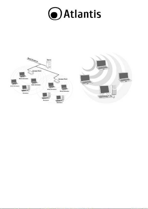
A differenza delle reti LAN le reti Wireless hanno due d ifferen ti modalità di
funzionamento: infrastructure ed ad-hoc. Nella configur azione Infrastructure una
rete WLAN e una rete WAN comunicano tra loro tramite un ac cess point. In una rete
ad-hoc i client wireless comunicano tra loro direttamente. La scelta tra le due
configura zioni è quindi dettata dalla necessità o meno di mettere in comunicazione una
rete wireless con una cab lata.
11
Page 12
Se i computer collegati alla rete wireless devono accedere a risorse o periferiche
condivise sulla rete cablata sarà necessario utilizzare la modalità Infrastructure . L’
Access Point trasmetterà le informazioni ai client wireless che potranno muoversi
all’interno di un determinato ragg io di azione. L’impiego contemporane o di più Acce ss
Point permetterà di estend ere l’area d i copertura del segnale. I clien t wireless
stabiliranno automaticamente il link con il dispositivo che fornisce il seg nale migliore
grazie alla fun zionalità roaming .
Modalità Infrastructure Modalità Ad-Hoc
Se la rete wireless ha dimension i relativamente ridotte e se le risorse condivise sono
dislocate sui personal computer che n e fanno parte, è possibile utilizzare la modalità
Ad-hoc. Questa modalità per mette di collegar e i client wireless tra loro direttamente
senza la necessità di un access p oint. La comunicazione tra i client è limitata
direttamente dalla distan za e dalle interferenze che intercorrono tra loro.
L’adattatore inoltre (su determinati sistemi Wind ows) supporta una modalità Access
Point che permette al PC con la scheda Wireless USB di fun zionare come un vero e
proprio Access Point (disponibile solo nei sistemi Windows 7/Vist a ed XP). In
questo modo è possibile costruire una vera è propria rete wireless a costi contenuti.
12
Page 13
Il throughput dell’adatta tore Wireless USB è limitato a soli
6Mbps se l’adattatore è c ollegato ad uno slot USB V1.1.
Il prodotto, nella release di driver V 2.1.2.0(USB) o V2.4.1.1
(PCI), è stato testato con kernel 2.6.29(PCI) e 2.6.31(USB).
Atlantis non gar antisce che il d ispositivo funzioni su
distribu zioni/kernel diver se da quelle elencate né, dato il
vasto numero di combinazioni, potrà offrire supporto. Si
invita a tal fine a reper ire gli ultimi driver direttamente sul sito
del produttore del chipset (www.ralink.com.tw).
Il prodotto, nella r elease di driver V 2.0.0.0, è stato testato
con sistemi Mac OS X 10.3/10.4/10.5/10.6. Per ogni
problematica si invita preventivamente a reperire gli ultimi
driver direttamente sul sito del produttore del chipset
(www.ralink.com.tw) ed eventualmente a contattarlo
direttamente.
1.2 Requisiti di sistema
Prima di proced ere c on l’installazione d el pr odotto verificar e di disp orre dei seguenti
requisiti:
PC con un o slot USB V2.0/1.1* libero (A02-UP1-WN, A02-UP-W300N, A02-UP4-
W300N)
PC con un o slot PCI 32bit libero (A02-PCI-WN, A02-PCI1-W300N)
Processore Intel® Pentium®III 600Mhz o compatibile con 512 MB RAM
Sistema operativo Windows 2000/XP/Vista/7, Linux e Mac OS X (solo USB)
45MB di spazio libero su disco
Lettore CD-Rom
2. CONTENUTO DELLA CONFEZIONE
Prima de ll’utilizzo, verificare che la scatola contenga i segu enti elementi:
NetFly USB Wireless Adap ter o NetFly PCI Wireless Card
Cavo di raccordo USB (nei soli modelli A02-UP-W300N o A02-UP4-W300N)
1 o 2 Antenne 2 dBi (A02-PCI-WN o A02-PCI1-W300N) e Low profile Bracket
Una guid a rapida mu ltilingua (Italian o, Inglese e Francese)
13
Page 14
In caso di installazione manuale dei driver /utility, fare
riferimen to alla cartella CDRom:\USB\<OS>, dove <OS>
rappresenta la versione di sistema operativo utilizzato. Nel
caso del modello PCI CDRom:\PCI\<O S>.
Questo manuale presuppon e che si utilizzi l’utility integra ta
per la configur azione dell’adattatore (spuntare dur ante
l’installazione la voce Install driver e RaLink WLAN Utili ty
nel caso d i Vista/7 oppure Ralink Configuration Tool nel
caso di Windows XP). Ladd ove si preferisca utilizzare il client
incluso (per i soli sistemi XP/Vista/7) spun tare Install Driver
Only nel caso di Vista/7 o Microsoft Z ero Configuration
Tool nel caso d i Windows XP e fare poi r iferimento
all’App endic e D.
Un Cd-Rom c ontenente utility e manuale dell’utente (Italiano, Inglese e
Francese)
Coupon di Garanzia e WEEE
Nel caso in cu i il contenu to non sia quello sovradescritto, contattare il proprio
rivenditore immediatamen te.
3. INSTALLAZIONE SOFTWARE
Questa sezione descrive la pro cedur a di installazione d ei d river e utility.
3.1 Installazione dei driver/utility
Inserire il CD-R om contenut o nella confezione e attendere l’avvio dell’interfaccia di
navigazione.
Cliccare A02-UP4-W300N o A02-UP-W300N o A02-UP1-WN o A02-PCI-
WN/A02-PCI1-W300N per accedere alla pagina relativa al prodotto.
Selezionare Utility e seguire le istruzioni visualizzate a schermo per completare
l’installazione.
Al termine dell’installazione, collegare il dispositivo al PC come da p aragrafo 4. Il
sistema rileverà ed installerà in maniera automatica il prodotto.
14
Page 15

Laddove il CDRom non dovesse avviarsi automaticamente è
possibile laciare il file di avvio localizzato in
CDRom:\start.htm.
3.2 Rimozione dei driver/utility
Per disinstallare l’adattatore W ireless effettuare la seguente p rocedura:
Chiudere eventuali applicazioni attive
Cliccare sull’ic ona Risorse del Computer ed andare in Pannello di controllo.
Cliccare sull’icona Installazioni Applicazioni (Programmi e Funzionalità),
evidenziare Ralink Wireless L AN Card e cliccar e su Aggiungi/Rimuovi
(Disinstalla), confermare poi la procedura di disinstallazione (alternativamen te
in Programmi->Ralink Wireless-> Uninstall RT -7x).
Al termine della procedura potrebbe essere chiesto un riavvio del PC.
A questo punto, una volta spento il PC, è possibile rimuovere la
scheda/adattatore.
4. INSTALLAZIONE HARDWARE
4.1 Installazione modelli PCI
Lo schema segu ente fornisce alcune informazioni di carattere generico in merito
all’insta llazione del prodotto. Per maggiori informazioni fare riferimento al manua le
della ma inboard.
Spegner e il PC e rimuovere la copertur a esterna. Localizzare uno slot PCI libero.
Posizionare N etFly PCI sullo slot PCI precedentemente localizzato e premere per
inserirlo.
Dopo aver blocca to correttamen te la scheda PCI c on l’apposita vite, r ichiudere la
copertura esterna del PC.
Connettere l’antenn a esterna.
Accendere il PC.
Terminato il reboot il Sistema Operativo troverà ed installerà la nu ova scheda.
4.2 Installazione modelli USB
Terminata l’installazione dei driver/utility e collegato l’adattatore ad un a porta USB il
Sistema Operativo provvederà ad installare i driver della nuova periferica.
15
Page 16
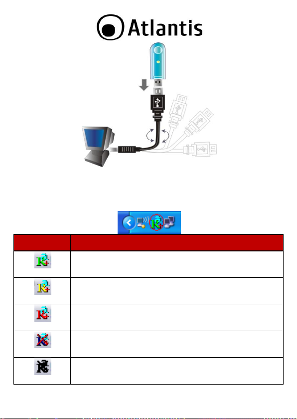
INDICAT ORE
SIGNIFICATO
Segnale ottimo
Segnale medio
Segnale basso
Non conn esso e/o errore di conn essione
Dispositivo non rilevato o non presente
4.3 Verifica dell’i nstall azione
Una volta termin ata l’installazion e, l’icona rappr esen tata in figura verrà visua lizzata
nella taskbar.
16
Page 17
Per disabilitare l’utility Zero Configuration di Windows XP,
fare riferimento all’appendice A.
In Wind ows XP. Per utilizzare l’utilit y Zero Configuration di
Microsoft per la configurazione Wireless cliccare sulla voce
Use Zero Co nfiguration as Configuration Utility. Una
volta in questa modalità è possibile tornare ad utilizzare
l’utility semplicemente cliccand o sulla voce Use RaConfig as
Configuratio n Utili ty.
Andando sull’icona, nella taskbar, e premendo il tasto destro del mouse verrà
mostrato un menu c ontenente 4 scelte:
Launch Config Utilities
Switch to STA + AP mode
Switch to AP mode
Exit
17
Page 18
Su sistemi opera tivi Windows VIST A l’interfaccia gr afica
potrebbe subire alcune variazioni.
5. RaUI FOR WINDOWS
RaUI è l’utility grafica per la ge stione e con figurazione del dispositivo.
L’Utility di configurazione include i seguenti tabs: Site Indagine, Link
Informazioni, Profilo, Advanced, Circa (tasto aiuto e chiusura).
Tramite la stessa sarà possibile configurare tutti i parametri necessari al corretto
funzionamento del p rodotto, attivare funzionalità avanzate quali il supporto WPS e
WMM e visualizzare informazioni sulle reti sen za fili rilevate dal dispositivo.
Al suo avvio, in maniera automatica, verrà effettuata una scansione delle frequenze al
fine di rilevare le reti wireless attive; il dispositivo si connetterà in maniera automatica
all’Access Point con segnale m igliore oppure all’Access Point segnalato nel pr ofilo di
accesso (se preconfigurato). Nel caso in cui tutte le reti r ilevate fossero protette e non
vi sia alcun profilo di connessione p reimpostato, il d ispositivo rimarrà in uno stato di
stand-b y in attesa della selezione manuale della rete d a parte dell’utent e.
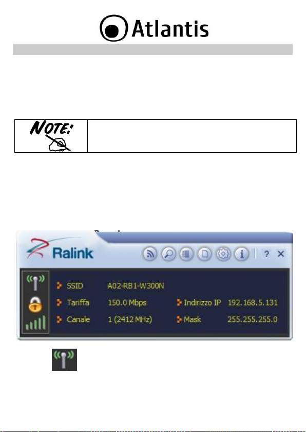
Per visualizzare i dati relativi alla connessione, cliccare sul pulsante presente nella
parte inferiore destra della sch ermata.
All'avvio dell'utility verrà visualizzata la shcermata di sotto.
Cliccare su per spegnere il modulo Radio.
18
Page 19
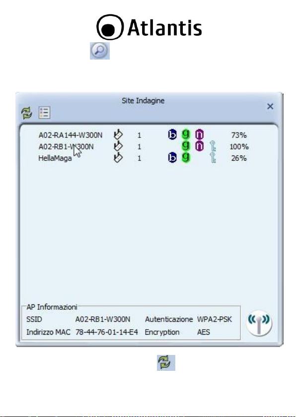
5.1 Site Indagine ( )
In questa schermata è possibile visualizzare le reti disponibili e visualizzarne i
parametri di base, come la p otenza del segnale, la sicurezza adottata dalla rete, il
canale d i connessione e l’SSID.
Tramite la pressione del tasto Rescan ( ), sarà possibile effettuare una
scansione delle frequ enze al fine di rilevare reti wireless attive.
19
Page 20
Dopo aver selezionato una rete dalla finestra, la pressione del tasto Aggiungi al
Profilo ( ) permette la creazione d i un nuovo profilo con i dati della rete
selezionata (nel caso in cui la rete sia protetta, verrà richiesto di digitare la password
per l’acc esso). Il profilo va poi attivato tramite la pressione d el tasto Active ( ).
Dopo aver selezionato un a rete dalla finestra, tramite la pressione del tasto Connect (
) permette la connessione alla rete selezionata (nel caso in cui la rete sia
protetta, p otrebbe essere necessaria la creazione di un nuovo profilo al file di
impostare i dati per l’accesso).
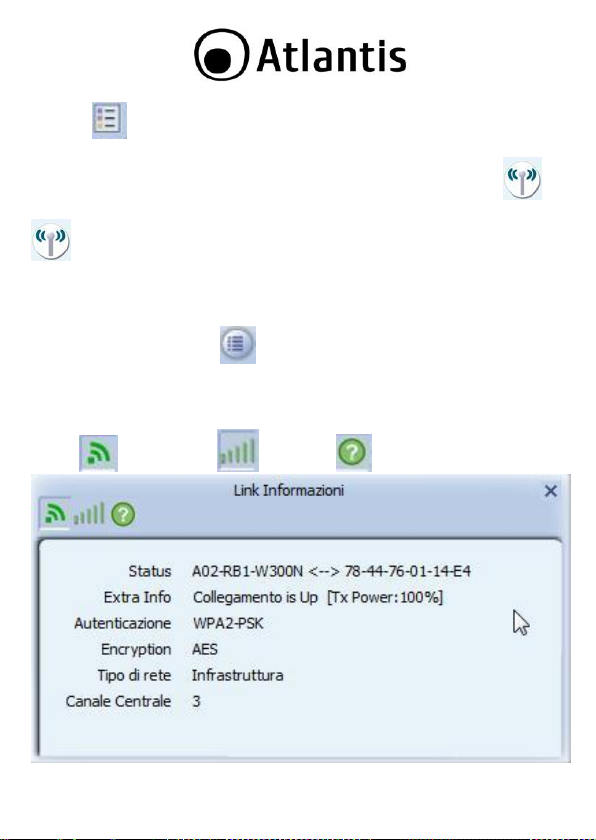
5.2 Link Informazione ( )
In questa schermata sarà possibile visualizzare le informazioni relative ad ogni profilo
di connessione.
Sono disponibili 3 schermate diverse, per accedere cliccare sull'icona relativa (Link
Status ( ), Throughpu t ( ), Statistics( )).
20
Page 21
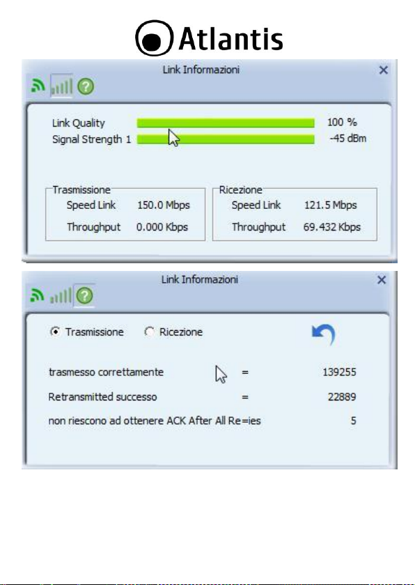
Transmit Statistics (selezionare il tab Trasmissio ne):
Frames Transmitted Successfully: Numer o di fra mes trasmessi con succ esso.
Frames Transmitted Successfully After Retry: Numer o di frames tr asmessi
con successodopo almeno un rinvio.
21
Page 22
Frames Fail To Receive ACK After All Retries: Numero di frame s trasmessi
senza successo.
Receive Statistics (selezionare il tab Ricezione):
Frames Received Successfully: Numero di frames ricevuti con successo.
Frames Received With CRC Error: Numero di frames ricevuti con errori d i
CRC.
Frames Dropped Due To Out-of-Resource: Frames tagliati per mancanza d i
risorse allocabili.
Duplicate Frames Received: Numero di frame duplicati.
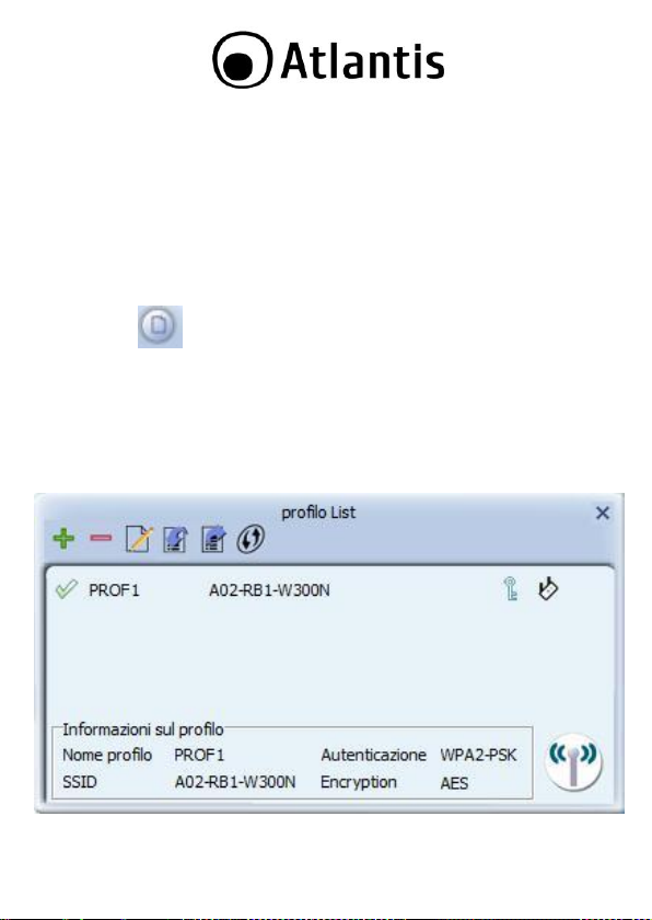
5.3 Profilo ( )
In questa schermata sarà possibile visualizzare le informazioni relative ad ogni profilo
di connessione, aggiungere nu ovi profili (si rimanda alla sezione B) o modificare quelli
esistenti.
Selezionando uno dei profili presenti nella Profile List, sarà possibile visualizzare le
informazioni relative alle impostazioni del profilo stesso.
In questa schermata sarà an che possibile visualizzare i pr ofili WPS (par. 5.6) esportati
decidere quale profilo di connessione attivare tra quelli esistenti.
22
Page 23
Tramite la pressione dei pulsanti Aggiungi ( ) ed Modifica ( ) sarà
possibilie creare dei nu ovi profili di connessione oppure modificare un profilo già
esistente.
Selezionando un profilo di connessione esistente, sarà p ossibile rimuoverlo tramite la
pressione del pulsante Elimina ( ).
Selezionando un profilo di connessione, sarà possibile u tilizzarlo per la conn essione
corrente tramite la pressione del pulsante Activate ( ).
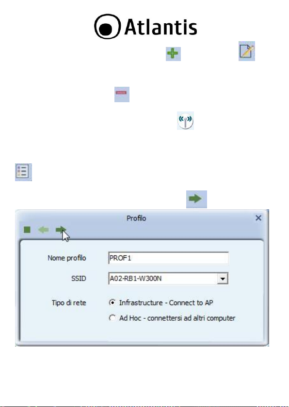
Per creare un nuovo profilo si hanno 2 strade diverse:
Creazio ne Profilo A:
Accedere a Site Indagine, selezionare l'SSID e cliccare sull'icona Aggiungi Profilo (
).
Si aprirà una nu ova finestra in cui inserire il Nome Profilo (nel caso in cu i la rete non
abbia protezione null'altro è richiesto). Cliccare sull'icona per proseguire.
Verrà mostrata una nuova finestra con la tipologia di cifratura rilevata (n on modificare
salvo in cui il dispositivo non riesca ad effettuare il c ollegamento), c liccare sull'icona
23
Page 24
per proseguire. Inserire adesso la password di cifratura della rete e cliccare
nuovamente sull'icona per terminare la crezione del profilo.
Non resta ad esso che attivare il profilo app ena creato. Cliccare sull'icona e poi,
dopo aver selezionato il profilo appena creato, cliccare su .
Dopo qualche secondo la scheda dovrebbe connettersi all'AP. E' possibile a questo
punto leggere maggiori dettagli circa il link e lo stato della scheda di rete wireless
(SSID, Velocità, Canale, IP, SubnetMask)
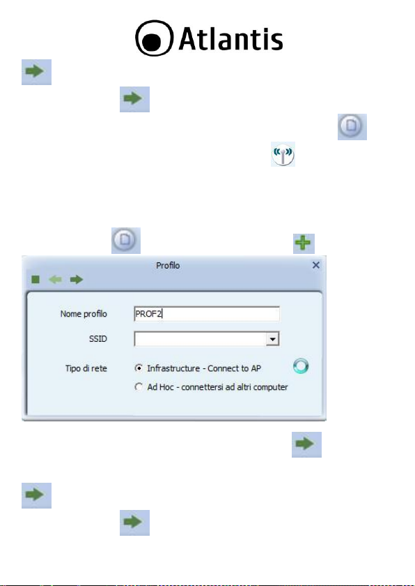
Creazio ne Profilo B:
Accedere a Profilo ( ), cliccare sul pulsanti Aggiungi ( ).
Si aprirà un a nuova finestra in cui inserire il Nome Profilo, e poi cliccare sulla combo
BOX SSID per visualizzare gli SSID rilevati. Cliccare sull'icona per proseguire.
Verrà mostrata una nuova finestra con la tipologia di cifratura rilevata (n on modificare
salvo in cui il dispositivo non riesca ad effettuare il c ollegamento), c liccare sull'icona
per proseguire. Inserire adesso la password di cifratura della rete e cliccare
nuovamente sull'icona per terminare la crezione del profilo.
24
Page 25
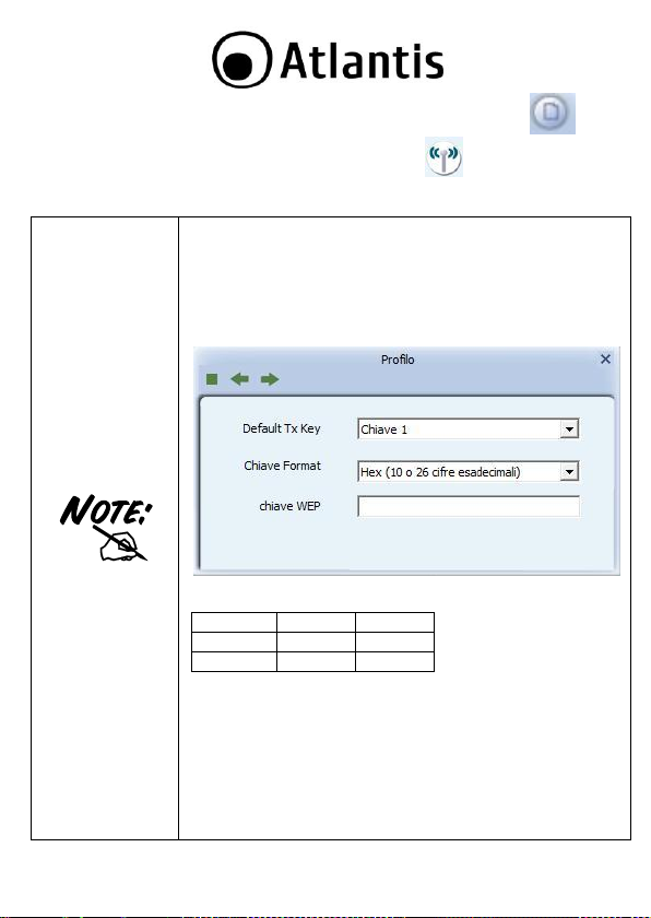
Configurazione WEP: Sceg liere Autenticazione=Shared ed
Encryption=WEP.
Sono disponibili 4 chiavi. Selezionare prima, dalla combo BOX
Default TX Key, il numero identificativo della chiave.
Introdurr e a questo punto la chiave associata. Ripetere
l’operazione per le 4 chi avi. E’ p ossibile immettere anche una
sola chiave WE P.
E’ po ssibile scegliere la lunghezza in b it [64,128] della ch iave e
la tipologia[ASCII, HEX], nella combo BOX Chiave Format.
ASCII
HEX
64 bit
5*X
10*Y
128 bit
13*X
26*Y
X=[(0~9, A~Z, a~z Alphanumeric]
Y=[0~9, A~F Hexadecimal]
Ad esempio una chiave WEP da 128 bit in ASCII potrebbe
essere “atlantisland1”. [una stringa composta da 13
caratteri].
Una chiave HE X da 128 bit p otrebbe essere u sa stringa di 26
caratteri [0,1,2,3,4,5,6,7,8,9,A,B,C,D,E,F].
Il WEP viene oggi considerata non come assolutamente
sicura e pert anto laddo ve possi bile si consiglia l’uso d el
Non resta ad esso che attivare il profilo app ena creato. Cliccare sull'icona e poi,
dopo aver selezionato il profilo appena creato, cliccare su .
25
Page 26
WPA.
Configurazione WPA/WPA2 -PSK: Scegliere
Autenticazione=WPA-PSK o W PA2-PSK ed
Encryption=T KIP o AES.
Inserire la chiave precondivisa da utilizzare tra AP e client nel
campo WPA PreShared Key.
Si consiglia di utilizzare sempre la modaità di sicurezza WPA2PSK(AES ), in quanto l’utilizzo degli algoritmi WEP e W PAPSK/WPA2-PSK(TKIP), basati su algoritmo RC4 e n on
sottoposti all’accelerazione AES, p otrebbero indurre importanti
degradazioni in termini prestazionali.
Configurazione WPA/W PA2.
Per utilizzare questo tipo di sicurezza, è r ichiesta la presenza
di un server R ADIUS per l’autenticazione d ei clien t.
Per informazioni aggiuntive su questa configurazione,
consultare la sezione di Help.
E' infine p ossibile, cliccand o rispettivamente sui bottoni , importare o
esportare profili.
Un click sul bottone permette di aggiungere un profilo WPS (l'AP deve
supportare tale caratteristica).
26
Page 27
La selezione errata d ella regione (nel campo Select Your
Country Domain) potrebbe portare ad un utilizzo di frequenze
vietate. E’ necessario scegliere la regione corretta. Consultare
la tabella ripielogativa contenuta all’Appendice A. Per l’I talia
scegliere 1 (Canali 1-13).
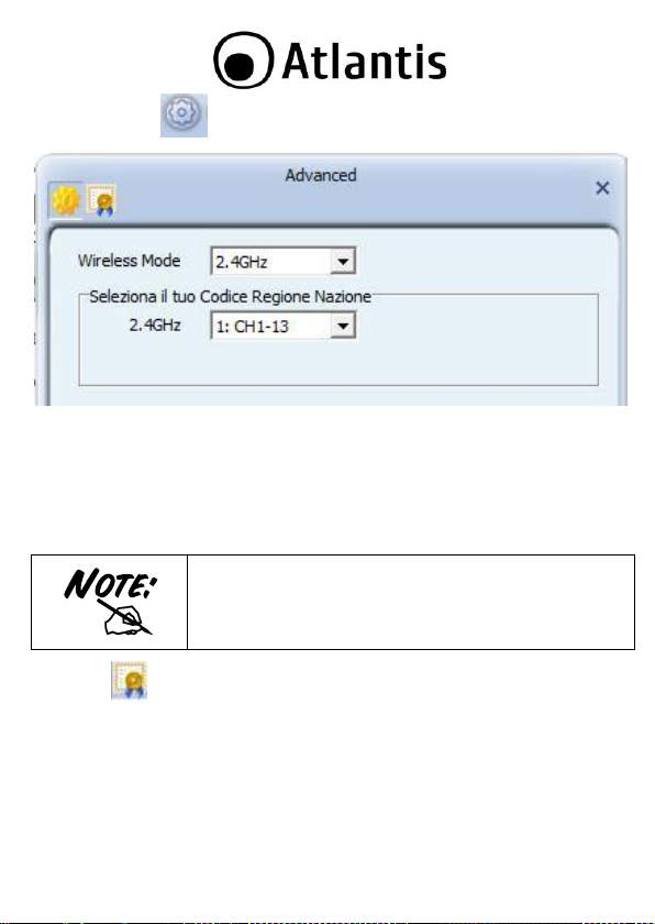
5.4 Advanced( )
Wireless mo de: S elezionare la frequenza utilizzata (nel caso di apparati b/g/n è
fissa sui 2.4Ghz)
Select Your Country Region Code: E’ possibile sceg liere la r egion e in cui il
dispositivo wireless verrà utilizzato. Questo, au tomaticamente, regolerà
l’appara to nel rispetto delle regole vigenti. La selezione errata della regione
(nel campo Country Domain) potrebbe portare ad un utilizzo di frequenze
vietate. E’ nec essario scegliere la reg ione c orretta.
Apply: Per rendere attivi I cambiamenti.
Cliccare su per provvedere all'installazione di un cer tificato.
27
Page 28
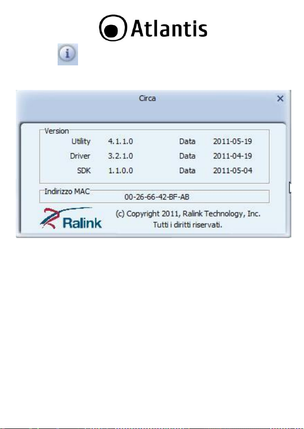
5.5 Circa ( )
In questa schermata sarà possibile visualizzare d ettaglio circa la versione di
driver/utility/SDK installata e l'indirizzo MAC della scheda.
28
Page 29

6. SUPPORTO OFFERTO
Per qualunque altro problema o dubbio sul fun zionamento del prodotto, è possibile
contattare il servizio di assistenza tecnica Atlantis tramite l’apertura di un ticket online sul portale http://www.atlantis-land.com/ita/supporto.php.
Nel caso n on fosse possibile l’accesso al portale di supporto, è altresì possibile
richiedere assistenza telefonica al nu mero 02/ 78.62.64.37 (consultare il sito per
verificare gli orari in cui il servizio viene erogato).
Per esporre eventuali richieste d i supporto prevendita o rich ieste di conta tto , si invita
ad utilizzare gli indirizzi mail info@atlantis-land.com oppure prevendite@atlantis-
land.com.
Atlantis SpA
Via S. Antonio, 8/10
20020 L ainate (MI)
Fax: +39.02.78.62.64.39
Website: http://www.atlantis-land.c om
Email: info@atlantis-land.com
29
Page 30
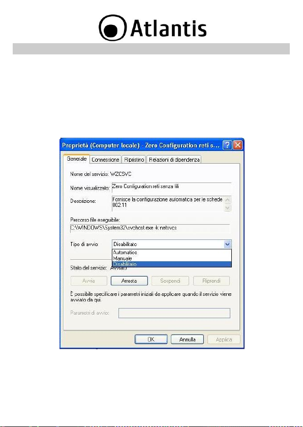
APPENDICE A: Disabilitare Zero Configuration
Di seguito è indicato come disabilitare il servizio Zero Configuration di Windows XP, al
fine di p oter controllare il disp ositivo tramite l’ut ility fornita a corredo:
Cliccare su Start e poi su Pannello di Controllo
Selezionare da l menu di sinistra la voce Visualizzazione classica
Cliccare su Strumenti di amministrazione
Cliccare su Servizi
Selezionare il servizio Zero Configuratio n e cliccare su Proprietà
Cliccare sul pu lsante Arresta p er terminare temporaneamente il servizio
Impostare il campo Tipo di Avvio su Disabilitato come da figura
30
Page 31

Senza WPS
Con WPS
(PIN mode)
Con WPS
(PCB mode)
Accensione dell’Acc es
Point
Accensione de ll’Acces
Point
Accensione dell’Acc es
Point
Accesso all’Access Point
Attivazione del client
Attivazione del client
Configurazione dell’SSID
Generazione in maniera
automa tica dell’SSID e
broadcasting della stessa.
Generazione in maniera
automa tica dell’SSID e
broadcasting della
stessa.
Attivazione della
sicurezza
Accesso al Registar
presen te sull’Access Poin t
Pressione del bottone
sull’Access Poin t e sul
client
Impostazione della
parola di accesso (WPA)
o delle chiavi di accesso
(WEP)
Insierimento del PIN
relativo al client da
aggiungere.
Attivazione del client
Avvio della
APPENDICE B: WPS (Wi-Fi Protected Setup)
WPS (Wi-Fi Protected Setup) è un insieme di specifiche mirate a facilitare
notevolmente le operazioni di aggiunta di dispositivi alla propria r ete wireless e la
messa in sicurezza della stessa con la sola pressione di un pulsante oppure tramite
l’immissione di un c odice PIN.
I dispositivi conformi alle specifiche WPS sono quind i in grado, in maniera molto
semplice, di rilevare le reti con tale supporto, acquisirne le impostazioni basilari(quali
SSID e canale) e negoziare in maniera del tutto automatica un profilo di sicurezza
utiizzand o i più avanzati a lgoritmi di crittografia come WPA e WPA2.
Nella configurazione PIN, un codice PIN univoco viene assegnato ad ogni dispositivo
che deve far p arte della rete; un adesivo o un etichetta posta sulla p arte p oster iore d el
client iden tificheranno tale codice in caso di PIN statico, o in alternativa questo verrà
generato in maniera dinamica e visualizzato tramite utility.
Questo codice viene utilizzato per assicurar e l’iden tificazione un ivoca della periferica e
per evitare in trusioni all’interno della rete da parte d i periferiche esterne. Gli uten ti, per
poter agg iunger e il di spositivo alla rete, dovranno in serire all’intern o del Registar
(presente a ll’interno dell’Acce ss Point), il c odic e PIN identificativo della periferica da
connettere.
Nella c onfigurazione PCB, l’utente sarà in g rad o di aggiungere p erifer iche e mettere in
sicurezza la propria rete tramite la semplice pressione di un pulsante (fisico sug li
Access Point e virtuale sui dispositivi client).
Di segu ito una tabella riassuntiva sui vantaggi del supporto WPS e sulle modalità di
configura zione:
31
Page 32

sincronizzazione tra AP e
client
Selezione della rete a cui
connettersi
Inserimento della chiave
di sicurezza per la
connessione del client
32
Page 33

La selezione errata d ella regione (nel campo Select Your
Country Domain) potrebbe portare ad un utilizzo di frequenze
vietate. E’ necessario scegliere la regione corretta. Consultare
la tabella ripielogativa contenuta all’Appendice A. Per l’I talia
scegliere 1 (Canali 1-13).
Il rang e di frequen ze radio usate dalle app arecchiature
Wireless IEEE 802.11g/b è suddiviso in “can ali”. I l numer o di
canali disponibili d ipend e dall’ area geografica di
appartenenza. E’ p ossibile selezionare canali differenti in
modo da eliminare eventuali interferenze con gli Access Point
vicini. L’interfer enza si verifica quand o due o più canali si
sovrappongono degradando le prestazioni, questa
sovrapp osizione è chiamata “O verlap”.
E’ consigliabile mantene re una distan za di 5 canali tra due
APPENDICE C: AP Mode
In questa modalità è possibile trasformare la scheda in un vero e proprio AP. Per
tornare alla modalità client, selezionare la voce Passa alla modalità AP e cliccarci
sopra.
L’Utility di configur azione, in m odalità Access Ponit, include 6 tabs: Config AP,
Advanced, Access Control List, Associated List, About.
Config AP ( )
In questa sezione è possibile configurare tutti i parametri tipici di un Access Point quali
SSSID (per nasconderlo spuntare la voce Hide SSID), Select Country Region
(frequen za di lavoro), il Canale, l'utilizzo dei 40Mhz (spuntare la voce Allow BW
40Mhz) ed infine l'autenticazione.
33
Page 34

utilizzati (es. AP1 p osizionato sul canale 1, AP2 p osizionato sul
canale 6).
Da questo si evince che soltanto 3 Access Point possono
essere usati in caso di sovrapposizioni spaziali(copertura) e
temporali(funzionan o allo stesso tempo).
Access
Policy
Allow All (Consenti
tutto)
Reject All (Rifiuta
tutto)
Disable (Disattiva)
Default
Access
Access
Reject
Access
Effetto
Tutti vengono abilitati
all’acce sso a meno di
quei MAC Add ress
presen ti nell’ Access
List.
Nessuno viene abilitato
all’acce sso a men o di
quei M AC Address
presen ti nell’ Access
List.
Tutti vengono
abilitati all’accesso.
Advanced ( )
In questa sezione è possibile configurare il T x Power/Idel Time/Beacon Interval
e la funzionalità Client Isolation (spuntare la voce No forwarding dei pacchetti tra
client wireless).
Access Control List ( )
In questa sezione è possibile configurare l’Access Point in modo d a fornire l’accesso
solo dopo aver controllato il MAC address del client wireless.
Associ ate List ( )
Vengono mostrate le informazioni (M AC Address, AID e Power Saving Mode) delle
stazioni loggate all’AP.
Circa ( )
In questa schermata sarà possibile visualizzare d ettaglio circa la versione di
driver/utility/SDK installata e l'indirizzo MAC della scheda.
34
Page 35

35
Page 36

Nel caso in cu i non sia possibile visualizzare la lista di reti
senza fili d isponibili, si prega di verificare la corretta
installazione dei driver del client USB.
APPENDICE D: Connessione usando il Client di Windows
In Windows XP/Vista e 7 è incluso un client che permette la gestione di un adattatore
wireless al pari delle Utility.
In Windows XP/Vista e 7 è incluso un client che permette la gestione di un adattatore
wireless al pari delle Utility.
Windows 7
Cliccare sull’icona di rete posiziona ta sulla System Tra y (vedi immagine) e
selezionare l’opzion e Centro connessioni di rete e condivi sione oppure
cliccare su Start -> Pannello di Controllo -> Centro connessio ni di rete
e condivisione.
Selezionare l’opzione Connessione a una rete dal menu di sinistra per
visualizzare la lista di reti wireless disponibili.
Selezionare l’SSID della r ete desiderata e premere sul pulsante Connetti per
avviare la procedura di connessione.
Al termine de lla procedura di c onnessione, un messagg io conferm erà l’avvenuta
connessione d el client USB all’AP.
36
Page 37

Nel caso in cu i non sia possibile visualizzare la lista di reti
senza fili d isponibili, si prega di verificare la corretta
installazione dei driver del client USB.
Windows VISTA
Cliccare sull’icona di rete posizionata sulla S ystem Tray (vedi imm agine) e
selezionare l’opzion e Centro connessioni di rete e condivi sione oppure
cliccare su Start -> Pannello di Controllo -> Centro connessioni di rete
e condivisione.
Selezionare l’opzione Connessione a una rete dal menu di sinistra per
visualizzare la lista di reti wireless disponibili.
Selezionare l’SSID della r ete desiderata e premere sul pulsante Connetti per
avviare la procedura di connessione.
Al termine de lla procedura di c onnessione, un messagg io conferm erà l’avvenuta
connessione d el client USB all’AP.
37
Page 38

Di seguito è indicato come disabilitare il servizio Zero
Configuration di Windows XP, al fine di poter controllare il
dispositivo tramite l’utility fornita a c orredo:
Cliccare su Start e poi su Pannello di Controllo
Selezionare dal menu di sinistra la voce
Visualizzazione classica
Cliccare su Strumenti di amministrazione
Cliccare su Servizi
Selezionare il servizio Zero Configuration e cliccare
su Proprietà
Cliccare sul pulsante Arresta per terminare
temporaneamente il servizio
Impostare il campo Ti po di Avvio su Disabilitato c ome da
figura
Windows XP
Fare d oppio click sull’icona d i rete posizionata sulla S ystem Tra y (vedi
immagine).
Selezionare l’SSID della r ete desiderata e premere sul pulsante Connetti per
avviare la procedura di connessione.
Al termine de lla procedura di c onnessione, un messagg io conferm erà l’avvenuta
connessione d el client USB all’AP.
38
Page 39

APPENDICE E: Configurazione indirizzo IP in DHCP Client
Questo capitolo fornisce alcune indicazioni su come impostare l’indir izzo IP alla scheda
Wireless usata in modalità DHCP client.
Configurazione del PC in Windows 2000
Andare su Start/Settings/Control Panel. Cliccare due volte su Network
and Dial-up Connectio ns.
Cliccare due volte su Local Area Connection.
In Local Area Connection Status/Wireless cliccare Properties.
Selezionare Internet Protocol (TC P/IP) e cliccare su Properties.
Selezionare l’opzione Obtain an IP address auto matically e
successivamen te Obtain DNS server address automatically.
Premere su OK per terminare la configu razione.
Configurazione del PC in Windows XP
Andare su Start e poi Panello di Controllo. Cliccare due volte su
Connessione di rete (se non fosse presente cliccare prima su: Passa alla
Visualizzazione Cl assica).
Cliccare due volte su Connessione alla rete locale (LAN)/Wireless.
Nel TAB generale cliccare Proprietà.
Selezionare Protocollo Internet (TCP/IP) e cliccare su Proprietà.
Selezionare l’opzione Ottieni automaticamente un indirizzo IP e
successivamen te Ottieni indirizzi server DNS auto maticamente.
Premere su O K per terminare la configurazione.
Configurazione del PC in Windows Vista
Andare su Start poi Pannello di Controllo (cliccare sulla voce
Visualizzazione classi ca) e qui cliccare due volte sull’icona Centro
Connessione di rete e Condivisione, poi cliccar e su Gestisci connessione
di rete.
Cliccare 2 volte sull’icona Local Area Connection/Wireless e cliccare su
Proprietà poi cliccare su Continua (p er continuare è nece ssaria l’utorizzazione
dell’utente).
Selezionare Protocollo Internet Versione 4 Protocol (TCP/IPv4) e
cliccare su Proprietà.
39
Page 40

Selezionare l’opzione Ottieni automaticamente un indiriz zo IP e
successivamen te Ottieni indirizzi server DNS auto maticamente.
Premere su O K per terminare la configurazione.
Configurazione del PC in Windows 7
Andare su Start poi Pannello di Controllo (cliccare sulla voce Icone Piccole
o Grandi) e qui cliccare due volte sull’ic ona Centro Connessio ne di rete e
Condivisione, poi cliccare su Modifica Impostazione Scheda.
Cliccare 2 volte sull’icona Local Area Connection/Wireless e cliccare su
Proprietà poi cliccare su Continua (per continuare è necessaria l’utorizzazione
dell’utente).
Selezionare Protocollo Internet Versione 4 Protocol (TCP/IPv4) e
cliccare su Proprietà.
Selezionare l’opzione Ottieni automaticamente un indirizzo IP e
successivamen te Ottieni indirizzi server DNS auto maticamente.
Premere su O K per terminare la configurazione.
40
Page 41

PROBLEMATICA
SOLUZIONE
Il personal computer
non rileva la periferica.
Accertarsi che la scheda n on sia fisicamente
danneggiata.
Accertarsi che la scheda sia c orrettamente
inserita nello slot PCI/USB.
Provare uno slot PCI/USB differente.
Accertarsi di aver installato correttamente
le utility di gestione.
Non è possibile
accedere a nessuna
risorsa Wireless
Assicurarsi che il PC sia acceso
Assicurarsi che siano disponibili reti wireless
a distanza di rilevamento.
Assicurarsi che le imp ostazioni d i rete
wireless siano corrette. Verificare con
l’ammin istratore di rete SSID, canale
utilizzato, ecc.
DOMANDA
RISPOSTA
Come posso disabilit are
il gestore delle
connessioni Wireless di
Window s XP
In Windows XP è raccomandato utilizzare il software
di gestione delle connessioni senza fili fornito a
corredo del prodotto. Una volta conc lusa
l’installazione del dri ver seguire i seguenti passi per
disabilitare il gestore delle reti wireless integrato in
Windows XP
Aprire il Pannello di controllo e cliccare
su Connessioni di rete.
Cliccare con il ta sto destro sull’ icona
Connessione di rete senza fili relativa
all’adattatore di r ete wireless, e selezionare
Proprietà.
Selezionare il tab Reti senza fili, e
deselezionare la voce Usa Windows per
APPENDICE F: Risoluzione dei problemi
Questo capitolo fornisce alcune soluzioni in merito ai problemi nei quali si potrebbe
incorrere durante l’installazione e l’u tilizzo del pr odotto. Leggere le seguenti
indicazioni per r isolvere eventuali prob lemi.
41
Page 42

configurare le impostazioni della rete
senza fili, cliccare q uind i su O K.
Posso avviare u n’
applicazione da un
computer remoto
presente s ulla rete
wireless?
Questo dipende direttamente dall’applicazione
stessa, se è stata progettata per lavorare in rete
(non fa differenza che sia wireless o cablata) non ci
sarà alcun problema.
Posso giocare in rete
con gli altri computer
presenti sulla WLAN?
Si, se il gioco è dotato di funzionalità multiplayer in
rete.
Cos’è lo Spread
Spectrum?
La trasmissione Spread Spectrum si basa sulla
dispersione dell’informazione su una banda mo lto
più amp ia di quella necessaria alla modulazione del
segnale disponibile. Il vantaggio che si ottiene da
questa tecnica di modulazione è infatt i una bassa
sensibilità ai disturb i radioelettrici anche per
trasmissioni a potenza limitata. Questa caratteristica
è ovviamente preziosa quando si devono
trasmettere dei dati.
Cosa sono DSSS e
FHHS?
DSSS (Direct-Sequence Spread -Spectru m): E' una
particolare tecnologia di trasmissione per la banda
larga che consente d i trasmettere ogni bit in
maniera ridond ante. E' adatta in particolare per la
trasmissione e la ricezione di segnali deboli.
FHHS (Frequency Hopping Spread Spectrum): è una
tecnologia che permette la cond ivisione tra più
utenti di uno stesso insieme di frequenze. Per
evitare interferen ze tra p erifer iche dello stesso tipo
le frequenze d i trasmissione cambiano sin o a 1.600
volte ogn i secondo.
Le informazioni inviate
via wireless posso no
essere i ntercettate?
La scheda offre funzionalità di crittografia avanzate
quali WPA e WPA2 e WEP fino a 128 bit; ciò
provvede a rendere sicure le trasmissioni dati
wireless. Il supporto per autenticazione tramite
server R ADIUS permette inoltre di garantire un
ulteriore livello di sicurezza alla rete wireless.
42
Page 43

Cosa è il WEP?
WEP è la sigla di Wired Equivalent Privacy, un
protocollo di sicurezza per le reti locali senza fili
(WLAN) definito dallo standard 802.11b.
Cosa è il WPA/W PA2?
WPA è la sigla di Wi-Fi Protected Access, un
protocollo di sicurezza per reti wireless basato su
protocollo crittografico RC4.
Introdotto con lo standard IEEE 802.11g, prevede
una gestione dinamica della chiave di autenticazione
al fine di eliminare i punti deboli dell’algoritmo WEP.
La succe ssiva introduzione de ll’acce lerazione in AES
ha inoltre permesso di ottenere importanti
miglioramenti sia in termini prestazionali che di
sicurezza.
Cosa è il Roaming?
Il Roaming è la capacità di un utente che possiede
un computer p ortatile di comunicare senza
interruzioni mentre si m uove liberamente all’interno
di una rete wireless la cui estensione è stata
incrementata grazie all’u tilizzo di più access point.
Cosa è la banda ISM?
Questa frequenza è stata messa a disposizione d alla
FCC, su rich iesta d elle aziende ch e intendevano
sviluppare soluzioni wireless per l'uso civile
quotidiano ed è generalmente contraddistinta dalla
sigla ISM band (Industrial, Scientific and Medical).
In questa frequenza operano solo dispositivi
industriali, scientifici e medici a basse potenze.
Cosa è lo st andard IEEE
802.11g ?
Lo standard 802.11g opera alla frequenza di 2,4 GHz
e quindi è pienamente compatibile con la più diffusa
versione b. Il vantaggio è che consente una velocità
di trasferimento di 54 Mbps, cinque volte superiore
allo stand ard 802.11b.
Cosa si i ntende per
802.11n draft?
Un draft è una b ozza di insieme di specifiche
sottoposte ad approvazione al fine di divenire
standard.
Al momento della stesura del presente manuale, il
futuro standard IEEE 802.11n è giunto alla seconda
43
Page 44

release di questa bozza (dr aft 2.0).
44
Page 45

Copyright Statement
No part of this publication may be reproduced, stored in a retrieval system, or
transmitted in any form or by any means, whether electronic, mechanical,
photocopying, recording or otherwise without the prior writing of the publisher.
Windows™ 98SE/2000/ME/XP/VISTA are trademarks of Microsoft® Corp. Pentium is
trademark of Intel. All c opyrigh t reserved.
The Atlantis logo is a registered trademark of Atlantis. All other names mentioned mat
be trademar ks or registered trademar ks of their respective owners. Sub ject to change
without notice. No liability for technical err ors and /or omission s.
Wireless LAN, Health and Authorization for use
Radio frequency electromagnetic en ergy is emitted from Wireless LAN d evices. The
energy levels of these emissions h owever are far much less than the electromagnetic
energy emissions from wireless devices like for example mobile phones. Wireless LAN
devices are safe for use frequency safety standards and recommenda tions. The use of
Wireless LAN devices may be restricted in some situations or environments for
example:
On board of airplanes, or
In an explosive environment, or
In case the interference risk to other devices or services is perceived or
In case the policy regarding the u se of Wireless LAN devices in specific organizations
or environments (e.g. airports, hospitals, chemical/oil/gas industrial plan ts, private
buildings etc.) is not clear, please ask for authorization to use these devices prior to
operating the equipment.
Regulatory Information/disclaimers
Installation and use of this Wireless LAN device must be in strict acc ord ance with the
instructions included in the u ser d ocumentation provided with the product. Any
changes or modifications made to this device tha t are not expressly approved by the
manufac turer ma y void the user’s a uthority to oper ate the equipmen t. The
Manufacturer is not responsible for any radio or television interference cau sed by
unauthorized modification of this device, of the substitution or attachment.
Manufacturer and its authorized resellers or distribu tors will assume no liability for any
damage or violation of government regulations arising from failing to comply with
these guidelines.
CE Mark Warning
In a domestic environment, this pr oduct may cause rad io interference, in which c ase
the user may be requ ired to take adequate measures.
identified as harmful
45
Page 46

Location
Frequency Band (MH z)
Power (EIRP)
Indoor (no restriction)
2400-2483,5
100mW(20dBm)
Outdoor
2400-2454
2454-2483,5
100mW(20dBm)
10mW(10dBm)
CE in which C ountries where the product may be used freely:
German y, UK, Italy, Spa in, Belgium, Netherland s, Portugal, Greece, Ireland, Denmark,
Luxemb ourg, Austria, Finland, S weden, Norway and Iceland.
France: except the channel 10 through 13, law pr ohibits the u se of other channels.
CE/EMC Restriction of Liability
The p roduct described in this handbook was d esigned, produced and approved
according to the EM C-regulations and is certified to be within EMC limitation s.
If the product is used in an uncertified PC, the manufacturer undertakes no warranty
in respect to the EMC limits. The described product in this handbook was constructed,
produced and certified so that the measured values are within EMC limitations. In
practice and under special circumstances, it may b e possible, that the product may be
outside of the given limits if it is used in a PC that is not produced under EMC
certification. It is also possible in certain cases and under special circu mstances,
which the given EMC peak values will bec ome out of tolerance. In these c ases, the
user himself is responsible for compliance with the EM C limits.
Declaration of Conformity
This equipment has been tested and found to comply with Directive 1999/5/CE of the
European Parliament and of the Council on radio equipment and telecommunications
terminal equipment and the mutual recogn ition of their conformity. After assessment,
the equipment has been found to comply with the following standard s: EN 300.328
(radio), E N 301 489-1, EN 301 489-17 (electromagnetic comp atibility) and EN 60950
(safety). This equipment may be used in all European Union contries and in all
countries applying Directive 1999/5/CE, without restriction, with the exception of the
following countries:
France (FR):
the frequency bans listed on the chart. For more info, consult the website
telecom.fr.
When this equipment is used outdoors, output power is limited to within
www.art-
Italy(IT):
Luxembourg:
Norway (NO):
of 20 km from the center of Ny Alesund.
For more info, c onsult the website
General authorization requie for network and service supply.
This subsection d oes not apply for geograph ical area within a radius
www.comunicazioni.it
46
Page 47

Russia (CCP):
Declaration of Conformity
Hereby We declare that this product is in compliance with the essential requirements
and other relevant pr ovision s of Directive “Electr omagnetic Compa tibility” and
1999/5/CE within CE Marking Requirememnt.
CE Declaration is available on the web site www.atlantis-land.c om.
only for indoor application.
procedures o f this equipment
The crossed-out wheeled b in symbol printed on the unit label or unit packaging
indicates that this equipment must not be disposed of as unsorted municipal waste but
it should be collected separately.
The waste of electric and electronic equipmen t must be treated separately, in order to
ensure that hazardous materials c ontained inside the equipmen t are n ot buried
thereby providing p otential future problems for the environment and human health.
Moreover, it will b e possible to reuse and recycle some parts of the waste of electric
and electronic equipment, contributing to reduce the quantities of waste to be
disposed of and the depletion of natural resources.
As user of this equipment, you are responsible to return this waste of electronic
equipment to an authorised collection facility set up by your Municipality. More
detailed information on your nearest collection centre can be obtained from your
Municipality or from other competent local entities.
If you are rep lacing the old equipment with a new equivalent product, the distributor
must take-back the old equipment free of ch arge on a one- to one basis as long as the
equipment is of equivalent typ e and fu lfilled the same functions as the supplied
equipment.
Your rôle in participating to the separate c ollec tion of waste of electric and electronic
equipment is essential to ensure that environmental protection and human health
objectives connected to a responsible treatment and recycling activities are achieved.
PS.: Th e abov e mentioned info rm ation a re rep ort ed h erewi th in compli ance with Dir ective
2002/96/CE , which requires a separate coll ectio n system and specific treatmen t and disposal
Important information for the co rrect recycle/treatment
47
Page 48

CE Logo with attention M ark ( ) aren’t fu lly
compliant with minimum dimensions requirement to
European Directive due to limited sticker area.
WEEE BIN Log o ( ) isn’t fu lly compliant with
minimum dimension s requirement to European Directive
due to limited sticker area.
Atlantis suggest to vistit the web site www.atlan tis-
land.com in order to retrieve update manual, techsheet
and driver.
Before starting, take a few minutes to read this manual.
Read all of instructions and save this manu al for later
reference.
procedures for the w aste of electri c and electronic equipments ( WEEE). For further and more
detail ed info rm ation, we invite you to vi sit our w ebsite at www. atl antis-land.com
48
Page 49

Thank you for purchasing the Wireless USB Adapter that provides the easiest way to
wireless networking. This User Manual contains detailed instructions in the operation
of this product. Please keep this manual for future reference.
1. PRODUCT OVERVIEW
Thank you for purchasing the NetFly that provides the easiest way to wireless
networking.
The N etFly (hereafter called the Adap ter) is a high-efficiency wireless LAN
Card/Adapter for wireless networking at h ome, in office or in public places. With the
Adapter, you can roam between conference room and office without being
disconnected the LAN cables; in addition, sharing files and pr inters can be easy tasks.
The NetFly is available to Microsoft Windows operating systems (Windows®
XP/2000/VISTA/7, Linux and Mac OS X(only for USB Adapter)) and can be integrated
into networking with either Ad-hoc mode (computer-to-compu ter, without an Access
Point), Infrastruc ture mode (computer-to-acce ss point, an Access Point is requ ired) or
Access Point Mode.
The device offers quick and easy access among wired network and wireless network.
The NetFly also supports WPA/WPA2 security, it increases the level of data protection
and access control for W ireless LAN.
MIMO radio technology (available only on 300Mbps devices) and multiple Antennas
provide extend ed coverage and low throughput fluctuations.
Last but not least WPS and WMM supports offers an high throughput for HD Video
Streaming and an easy way to make sure you wireless network.
Access Point Mode: PC with Wireless USB/PCI Adapter/Card work as an Access
Point. You can save m oney and make a little network using Your PC+Adapter as an
Access Point. This features is available only on selected SO (XP/Vista/7).
The NetFly AP4 WN is a wireless USB 2.0 adapter that p rovides instant access to data
like news, weather, sports and stock information on your Samsung HDTV screen. It
also supports Blu-ray Live with Netflix, Pandora and PC streaming of pictures and
videos.
49
Page 50

1.1 How the Adapter works
Ad-hoc Mode: An Ad-hoc network is a local ar ea network or other small network,
especially one with wireless or temporary plug -in connections, in wh ich some of the
network devices are part of the n etwork only for the duration of a communications
session. Users in the network can share files, prin t to a shared pr inter, and access the
Internet with a shared modem. In this kind of network, new devices can be quickly
added; however, users can only communicate with other wireless LAN computers that
are in this wireless LAN workgroup, and are within range.
Infrastructure Networking Mode: The difference between Infrastruc ture network
and Ad-h oc network is that the former one includes an Access Point. In an
Infrastructure n etwork, the Access Point can manage the bandwidth to maximize
50
Page 51

The throughput is limited to 6Mbps if the wireless N Mini
USB adapter is plugg ed on an USB rev1.1 slot.
bandwidth utilization. Additionally, the Access Point enables users on a wireless LAN to
access an existing wired network, allowing wireless users to take advantage of the
wired networks resources, such as Internet, email, file transfer, and printer sharing.
The scale and range of the Infrastructure networking are larger and wider than that of
the Ad-hoc networking.
Access Point Mode: PC with Wireless USB/PCI Adapter/Card work as an Access
Point. You can save m oney and make a little network using Your PC+Adapter as an
Access Point. This features is available only on selected SO (XP/Vista/7).
1.2 System Requirements
Before installing the Adap ter, your PC should meet the following:
PC with availab le USB V2.0/1.1* slot (A02-UP1- WN, A02-UP-W300N, A02-UP4-
W300N)
PC with availab le PCI 32bit slot (A02-PCI-WN/A02-PCI1-W300N)
Intel® Pentium®III 600Mhz or comp atible processor with 512 MB RAM
Windows® 2000/XP/Vista/7, Mac OS X(only USB) and Linux operating system
Minimum 45 Mbytes free disk space for installing the driver and utilities
CD-Rom drive
*When plug the device in the USB 1.1/1.0 port, the real throughpu t will b e up to
6Mbps only wh en running 11Mbps or higher speed.
2. PACKAGE CONTENTS
Open the box of the NetFly Wireless Adapter/Card and carefully unpack it. The box
should contain the following items:
One NetFly USB Wireless Adap ter or NetFly PCI Wireless Card
USB Cab le (only for A02-UP-W300N, A02-UP4-W300N)
1/2 2 dBi Antennas (A02-PCI-WN or A02-PCI1-W300N)and Low Profile Adapter
Bracket
51
Page 52

If you need to install the driver/utility manually, refer each
Windows OS to the following CD-Rom directory path: CD-
ROm:\USB\< OS> or CD-ROm:\PCI\< OS>
Windows XP/Vista/7 have its own Wireless Utility; you can
either u se the utility of Windows XP/7/Vista or the provided
utility. In this case during installation please select Install
Driver Only (for 7/Vi sta) or Microsoft Zero
Coniguration Tool (for XP).
One MultiLanguage Quick Start Guide (Eng lish, French and Italian)
CD-Rom with Utility, Driver and Manual (English, French and Italian)
1 x Warranty Card and 1 x WEEE Card
If any item is found missing or damag ed, please con tact your local reseller for
replacement.
3. SOFTWARE INSTALLATION
This section will lead you to install the driver and utility of the Wireless LAN
Adapter/Card.
3.1 Utility and Driver Installation
Insert the CD-ROM and the Auto-run program will appear (a lternatively, op en a
file browser and double click on the start.htm file located in the CD directory).
Click on A02-UP4-W300N icon (or A02-UP-W300N or A02-UP1-WN or
A02-PCI-WN /A02-PCI1-W300N) to select NetFly USB/Card Home Page.
Select Utility and the install wizard will begin installing the software. Follow
the install wizard instructions to complete the in stallation (select Install Driver
and RaLink WLAN Utility (for Vista/7) or Rali nk Configuration Tool (for
XP)).
Follow the Install Shield Wizard Instructions. Click Next to continue and finish
it.
Please plug Wireless USB Adapter into US B Slot or PCI Card ( shut down before the
computer the PC) into PCI Slot (check the next section), it will be recognized and auto
installed.
The installation progr am will help you to setup the Wireless LAN utility.
52
Page 53

Make sure that there is a well environment that there is no
much intrusion to have a b etter connection.
3.2 Uninstallation
To uninstall the Wireless USB/PCI Adapter/Adapter, go to the Control Panel of your
system.
Open the Add/Remove Programs.
Select the Ralink Wireless Lan Card in the Add/Remove Programs and
then click on the Remove.
Click on Remove ALL [or Overwrite the older version install without
remove].
Then chose Yes, I want to restart my co mputer and c lick Finish.
Now You can remove the Adapter/Card.
4. HARDWARE INSTALLATION
4.1 Hardware Installation for PCI Card
The setup of the Wireless LAN Card can be performed using the following steps:
Shut down the computer, unplugs its power cord, and remove the chassis cover.
Insert the contact edge of the NetFly card in to the connector of any available
PCI Bus Master expansion slot. Press the card firmly into the conn ector such that
the card’s con tacts are fully seated in the c onnector.
Install th e bracket screw and secure the card to the compu ter chassis.
Visually inspect the PCI Adap ter and make sure that it is fully plugged in to the
PCI slot.
Cover the compute r’s cha ssis.
Switch compu ter power on.
The OS will start an automatic h ardware discovery procedure in order to find and
install the best driver available for the device.
53
Page 54

4.2 Hardware Installation for USB Adapater
Please plug the Wireless adapter (only when requested from OS) to a free USB slot on
the PC.
54
Page 55

ICON
SIGNAL QUALITY
Excellent
Good Weak
Not connected yet
Device n ot recognized
In wind ows XP, it provides wireless configuration utility
named windows zero configuration which provides basic
configura tion function for WirlessUSB Adapter. Currently,
Ralink’s utility provides WPA-PSK supplicant’s functionality. If
user requ ired WPA function.
Please select WZC as main utility. To make it easier for
user to select the correc t utility. RaConfig will let user
make the selection when it first ran after XP boot. Click the
4.3 Using the Configuration Utility
When the Wireless LAN Adapter was installed, you will see the icon on the Windows
task bar. The user can configure the wireless settings using the Wireless Adapter
Configuration Utility. Double-click the utility icon that appears in the taskbar
When You click on this icon in the Windows ta sk bar You can see 4 differen t links:
Launch Config Utilities
Switch to AP mode
Open Diagno stic T esting Mode
Exit
55
Page 56

icon of will bring up the selection window and let user
make the selection. When coexisting with WZC, RaConfig
only provides monitoring func tion, such as link status, site
surveying, statistic counters and advance feature status
5. RaUI CONFIGURATION UTILITY
Double-click the Wireless LAN icon (or righ t-click and then select Launch Config
Utilities) to launch the Configuration Utility. With the Wireless Adapter utility, users
can configure all the function s pr ovided b y the Wireless Monitor Utility. Double-click
the utility icon that appear s in the taskbar.
The Wireless Monitor Utility includes 10 tabs: Profile, Network, Advanced,
Statistics, WMM, WPS, CCX, Radio On/Off, About and Help.
5.1 Profile
Profile can book keeping your favorite wireless setting among your home, office, and
other pub lic h otspot. You may save multiple profiles, and activate the correct one at
your preferenc e.
56
Page 57

When u se site survey to make the connection, none of profiles
will have the c onnection status icon.
Click Add button in order to make a new profile, and click Delete button, after
choose a profiule, in order to erase an existing profile.
Click E dit button to change the selected Profile or click Activate button, after choose
a profile, in ord er to use selected profile for current connection.
If you need to add a n ew connection profile by pressing Add button, the following
screen will be show:
Profile Name:
SSID:
Power Save Mode:
Awake Mode) or Power Saving Mode.
Name of profile, p reset to PROF* (* indicate 1, 2, 3,).
AP or Ad-hoc name.
Select power saving mode between CAM (Constant
57
Page 58

Network Type:
Infrastructure.
RTS Threshold:
Click on Authentication and Security tab in order to configure wirless security.
Fragment Threshold:
Choose network type between Adhoc or
Set value by scrolling bar.
Set value b y scrolling bar.
58
Page 59

How to configure WEP security:
If you select 64bit in Hex format, you must type 10 values in
the following rang e (0~F, hexadecimal), or 64bit in ASCII
format, you must type 5 valu es in the following range (0~9,
A~Z and a~z Alphanumeric).
If you select 128bit in Hex format, you must type 26 values
(0~F, hexadecimal), or 128bit in ASCII format, you must type
13 values in the following range (0~9, A~Z and a~z
Alphanu meric).
ASCII
HEX
64 bit
5*X
10*Y
128 bit
13*X
26*Y
X=[(0~9, A~Z, a~z Alphanumeric]
Y=[0~9, A~F Hexadecimal]
Be sure that the USB Adapter and the wireless station (AP)
were set in the same key.
WEP is not completely secure. If possible please use WPA-PSK.
5.1.1 Configuring WEP security
Authentication Type:
Encryption Type:
WEP Key ( 1-4):
data encr yption.
Hexadecimal/ ASCII:
Press Show Password to view keys in clear mode.
Select Open or Shared authentication.
Select WEP.
Inser t WEP keys to use and select wh ich one to use for
Select input format for the key.
59
Page 60

Atlantis suggest to use WPA2-PSK with AES. WEP or WPA/WPA2-PSK
with TKIP can introduce degradations of wireless performanc e.
5.1.2 Configuring WPA-PSK / W PA2-PSK security
Authentication Type:
Encryption Type:
WPA Pre-shared Key:
client (8-32 ch aracters).
802.1x Setting:
RADIUS server.
Press Show Password to view pre-shared key in clear mode.
5.1.3 Configuring WPA / W PA2 s ecurity
To use this type of security, RADIUS server is needed.
For additional information about this configuration, please see section Help.
Select WPA-PSK or WPA2-PSK.
Select encryption type b etween T KIP or AES.
Insert pre-shared key to use between AP and
Select this option if is needed make authentication by
60
Page 61

If selected AP supports WEP or WPA/WPA2 You have to chose
Authentication and Security tab in order to connect to the
wireless network.
5.2 Network
Under the Network page, system will display the information of surrounding APs from
last sc an result. List inf orma tion’s include SSID, Signal, Chann el, Encr yption algorithm,
and Network type as picture shown.
Rescan: Issue an rescan command to wireless NIC to update information on
surround ing wireless network.
Connect: Command to connect to the selected n etwork.
Add to Profile: select an AP profile, click Add to Profile. It will bring up profile page
and save user’s setting to a new profile.
61
Page 62

5.3 Advanced
Wireless Mode: Select wireless mode (2.4Ghz)
Country Region Code: eight countries to choose. Country chan nel list.
Select the country where you are using this Wireless Device, users are
responsible for ensuring that the chann el set configuration is in compliance
with the regulatory standards of these countries. Please chek on the
Appendix A fore more information.
Enable TX Burst: Ralink's pr oprietary frame burst mode.
Enable TCP Windows Size: Optimise the TCP window size to allow for
greater throughput.
Fast Roaming at: enables fast roaming, which is set by the transmit
Click Apply in order to use these new settings.
power.
5.4 Statistics
Statistics page displays the detail counter information based on 802.11 MIB counters.
This p age translates tha t MIB counters into a format easier for user to understand.
The picture shows the detail pag e layout.
62
Page 63

Frames Transmitted Successfully: Frames successfully sent.
Frames Transmitted Successfully Without Retry: Frames successfully
sent without any retry.
Frames Transmitted Successfully After Retry: Frames successfully
sent with one or more reties.
Frames Fail To R eceive ACK After All Retries: Frames failed transmit
after hitting retry limit.
RTS Frames Successfully Receive CTS: Successfully receive CTS after
sending RTS frame.
RTS Frames Fail To Receive CTS: Failed to receive CTS after sending
RTS.
Frames Received Successfully: Frames received successfully.
Frames Received With CRC Error: Frames received with CRC error.
Frames Dropped Due To Out-of-Reso urce: Frames dropped due to
resource issue.
Duplicate Frames Received: Duplicate received frames.
Reset counters to zero.
5.5 WMM
This screen allow to enable WMM func tionalities. Press
function.
WMM
button to enable this
63
Page 64

WMM - Power Save Enable: Enable this function and select power
saving mode. Please select which ACs you want to enable. Then click
Apply button. The setting of enabling WMM – Power Save is successfully.
Direct Link Setup: Th is function will be ready for fu ture release of driver.
Check on the OnLine help d esk in ordere to obtain more information.
64
Page 65

Before starting procedure, be sure that:
There isn’t an y AP in W PS mod e active.
Access Point that are in WPS mode have finished its
5.6 WPS
WPS is a set of specifications (supported by 802.11n draft) that will help you to
configure your network easily.
It exists 2 ways to use WPS: PBC (Push Button Configuration) mode and PIN mode.
WPS AP List: Show a list of APs with WPS supp ort.
WPS Profile List: Show a list of WPS profile pre-configured by user.
Config Mode: Choose config mode b etween E nrollee or Registar.
Rescan: Make a new scan of frequencies to search APs with WPS support.
Information: Show information about WPS AP selected.
Renew: Make a new PIN code for this de vice.
Detail: Show information about WPS Profile selected.
Connect: Make a connection with WPS profile selected.
Disconnect: Disconnect WPS profile.
Export Profil e: E xport WPS profile selected to Profile.
Delete: Delete WPS profile selected.
5.6.1 WPS ( PBC Mode) Configuration
Following, is possible to find a procedure to configure a wireless secure c onnection b y
WPS (PCB Mode):
65
Page 66

scan for devices.
Set
Enrollee
Click on PBC button to start sincronization process between AP and client.
Press PCB button on AP.
For more informations:
http://www.wi-fi.org/files/kc_80_20070104_Introducing_Wi-Fi_Protected_Setup.pdf
http://www.wi-fi.org/files/wp_18_20070108_Wi-Fi_Protected_Setup_WP_FINAL.pdf
mode in Config Mode.
5.7 CCX
In order to obtain m ore info about CCX (Cisco Compatible eXten sions) please check
OnLine Help.
5.8 Radio On/Off
It can enable or disable RF modu le.
66
Page 67

5.9 About
The About section shows the Driver Version, Firmware Version, MAC Address, IP
Configuration and the Utility version.
Please see this screen before download driver upgrade from www.atlantis-land.com
5.10 Help
Click here in order to watch OnLine Help.
67
Page 68

6. Support
For technical questions and support, please contact our help-desk by ticket on
http://www.atlantis-land.com/ita/supporto.php.
For generic informations, please send an e-mail to info@atlantis-land.com.
For presales informations, please send an e-mail to prevendite@atlantis-land.com.
Atlantis SpA
Via S. Antonio, 8/10
20020 L ainate (MI)
Fax: +39.02.78.62.64.39
Website: http://www.atlantis-land.c om
Email: info@atlantis-land.com
68
Page 69

APPENDIX A: AP Mode
Double-click the Wireless LAN icon (or right-clic k and then select Launch Config
Utilities) tand chose Switch t o AP mode. With the Wireless USB Adapter utility, users
can configure all the function s pr ovided b y the Wireless Monitor Utility. Double-click
the utility icon that appear s in the taskbar.
The Wireless Monitor Utility includes six tabs: Config, Access Control List, Mac
Table, Event Log, Statistics and About.
Config
This page can setting and display Soft AP detail information.
Definition of each field:
Wireless Mode: Select wireless mode(2.4 Ghz).
SSID: AP name of user type. User also can select [Use Mac Address] to
display it. System default is SoftAP-XX.
Country Region Code: eight countries to choose. Country channel list.
Select the country where you are u sing this Wireless Device, users are
69
Page 70

The rang e of radio frequencies used by IEEE 802.11g wireless devices is
called a “chann el”. Ch anne ls available depend on your g eogr aphical area.
You may have a choice of channels (for your region) so you sh ould use a
different channel than an adjacent AP (access point) to reduce
interference. In terference occurs when radio signals from different access
points overlap causing interference and degrading performance.
Adjacent channels partially overlap however. To avoid interference due to
overlap, your AP should be on a chann el at least five channels a way from
a channel that an adjacent AP is u sing. For example, if your region has 11
channels and an adjacent AP is using channel 1, then you need to select a
channel between 6 or 11.
Access
Policy
Allow All
Reject All
Disable
Default
Access
Access
Reject
Access
Result
Access Control function
doesn’t allow s client s
whose MAC addresses
in the list will be ab le to
connect to this Access
Point.
Access Control func tion
allows clients whose
MAC addresses in the
list will be able to
connect to this Access
Point.
Access Point doesn’t
check MAC
addresses
responsible for ensuring that the chann el set configuration is in compliance
with the regulatory standards of these countries. Please chek on the
Appendix A fore more information.
Beacon (ms): The time between two beacons. System default is 100 ms.
TX Power: Manually force the AP transmits power. System default is
100%.
No forwarding among wireless clients: No beacon among wireless
client, clien ts can’t share information each other. System default is no
forwarding.
Hide SSID: Don’t display AP name. System def ault n o hide.
Allow BW 40Mhz: In order to use 40Mhz channel.
Click Apply in order to save all settings.
For more info please click on helb button.
Access Control
AP conn ected or can’t connect with Mac address that u ser setting.
Mac Table
This screen displays the station detail information of current connection.
70
Page 71

Detail information:
MAC Address: The stati on’s Mac address of current connection.
AID: Raise value by curren t connection.
Power Saving Mode: The station of current connect whether it have to support.
Event Log
Record S oft AP all event time and message.
Event Time (yy/mm /dd-hh:mm:ss): Record event time.
Message: All event message.
Statistics
Please check 5.4.
About
Please check 5.9.
71
Page 72

If any wireless network is available, p lease check that the
USB/PCI wireless client is correctly installed on your PC.
If any wireless network is available, p lease check that the
USB/PCI wireless client is correctly installed on your PC.
APPENDIX B: Connect to a network using Windows client
MS Wind ows XP and Wind ows VISTA/7 can manage the USB/PCI client with its
embedded utility for wireless networks; Windows 2000 and MAC OS X requires an
external management utlity (provided on the CD) to set and manage the USB/PCI
wireless client.
Windows 7
You can access the Connect to a network dialog box from man y locations in
Windows 7, including the following:
By clicking Start, and then Control Panel (select Large/Small Icon) then
click on Network and Sharing Center icon. Click on Connect to a Netwok.
From the Manage wireless connections (in the Wireless) select the
wireless network SSID and click Connect.
Windows VISTA
You can access the Connect to a network dialog box from man y locations in
Windows Vista, including the following:
By clicking Start, and then Co nnect to from the Windows Vista desktop
From the Manage wireless connections dialog box
From the Connect/Disconnect context menu option of a wireless network
adapter in the Network Connections folder.
Select Wireless (on the combo box) in the filed Show, select the wireless
network SSID and click C onnect.
Windows XP
Double click on Wireless network icon on the system tray ( see p icture).
72
Page 73

If any wireless network is available, p lease check that the
USB/PCI wireless client is correctly installed on your PC.
Select th e wireless network SSID and click Connect.
73
Page 74

APPENDIX C: IP Address in DHCP Client Mode
Configuring PC (Windows 2000)
Go to Start / Settings / Control Panel. In the Control Panel, double-click on
Network and Dial -up Connections.
Double-click LAN Area Connection/Wireless.
In the LAN Area Co nnection/Wireless Status window, click Properties.
Select Internet Protocol (TCP/IP) and click Properties.
Select the O btain an IP address automatically and the Obtain DNS
server address automatically rad io buttons.
Click OK to finish the configuration.
Configuring PC (WindowsXP)
Go to Start / Control Panel (in Classic View). In the Control Panel, double-
click on Network C onnections.
Double-click Local Area Connectio n/Wi reless.
In the LAN Area Co nnection/Wireless Status window, click Properties.
Select Internet Protocol (TCP/IP) and click Properti es.
Select the O btain an IP address automatically and the Obtain DNS
server address automatically rad io buttons.
Click OK to finish the configuration.
Configuring PC (Windows Vista)
Go to Start / Control Panel (in Classic View). In the Control Panel, double-
click on Network and Sharing Center icon.
Click Manage Network connections then double-click Local Area
Connection/Wireless and click Properties.
Click Continue (Windows needs your permission to continue).
Select Internet Protocol Version 4 (TCP/IP) and click Properties.
Select the O btain an IP address automatically and the Obtain DNS
server address automatically radio buttons.
Click OK to finish the configuration
74
Page 75

Configuring PC (Windows 7)
Go to Start / Control Panel (select Large/Small Icon). In the Control
Panel, double-click on N etwo rk and Sharing Center icon.
Click Change Adapter Settings then double-click Local Area
Connection/Wireless and click Properties.
Click Continue (Windows needs your permission to continue).
Select Internet Protocol Version 4 (TCP/IP) and click Properties.
Select the O btain an IP address automatically and the Obtain DNS
server address automatically radio buttons.
Click OK to finish the configuration
75
Page 76

QUESTION
SOLUTION
My computer cannot
find the Adapter
Make sure the Adapter has no physical
damage.
Make sure the Adapter is proper ly in serted
into USB slot.
Try the Adap ter in other USB slots.
Try another Adapter in that particular USB
slot.
Cannot access any
network resources from
the co mputer. Make
sure that the notebook
PC is powered on
Make sure that the notebook PC is p owered
on.
Make sure that the Adapter is configured
with the same SSID and security options as
the other computers in the infrastructure
configura tion.
Disable “Window s XP
Wireless Z ero
Configuratio n
In Windows XP, it is recommended that you use the
WLAN 802.11n Utility. Right after the installation,
before opening the Utility, please follow the steps
below to disable the Windows XP Zero
Configuration:
Go to Control Panel and double click
Network Connections.
Right-click Wireless Network
Connection of WLAN 802.11n Wireless
LAN, and select Properties.
Select Wireless Netw orks tab, and
uncheck the check box of Use Windows
to configure my wireless network
settings, and then click OK.
Can I run an
application from a
remote computer over
the wireless network?
This will depend on whether or not th e application is
designed to be used over a network. Consult the
applica tion’s user guide to determine if it supports
operation over a network.
Can I play computer
games with other
Yes, as long as the game supp orts multiple players
over a LAN (local area network).
APPENDIX D: Troubleshooting
This ch apter provides solutions to problems that may occur during th e in stallation and
operation of the WLAN 802.11n USB Adapter. Read the descriptions below to solve
your problems.
76
Page 77

members of the
wireless network?
Refer to the g ame’ s user guide for more
information.
What is Spread
Spectrum?
Spread Spectrum technology is a wideband radio
frequency technique developed by the military for
use in r eliable, secure, mission-critical
communications systems. It is designed to trade off
bandwidth efficiency for reliab ility, integrity, and
security. In other word s, more bandwidth is
consumed than in the case of narrowband
transmission, but the trade-off produces a signal
that is, in effect, louder and thus easier to detect,
provided that the receiver knows the parameters of
the spread-spectrum signal being broadcast. If a
receiver is not tuned to the right frequency, a
spread-spectrum signal looks like background noise.
There are two main alternatives, Direct Sequence
Spread Spectrum (DSSS) and Frequency Hopping
Spread Spectrum (FHSS).
What is DSSS? What is
FHSS? And what are
their differences?
Frequency-Hopping Spread-Spectrum (FHSS) uses a
narrowband carrier that changes frequency in a
pattern that is known to both transmitter and
receiver. Properly synchr onized, the net effect is to
maintain a single logical channel. To an unintended
receiver, FHSS appears to b e short-duration impu lse
noise. Direct-Sequence Spread-Spectrum (DSSS)
generates a redundan t bit pattern for each bit to be
transmitted. This bit pattern is called a chip (or
chipping code). The long er the chip, the greater the
probability that the original data can be recovered.
Even if one or more bits in the chip are damaged
during transmission, statistical techniques
embedded in the r adio can recover the original data
without the need for retransmission. To an
unintended receiver, DSSS appears as low p ower
wideband noise and is rejected (ignored) by most
narrowb and receivers.
Would the informatio n
be intercepted while
WLAN features two-fold protection in security. On
the hard ware side, as with Direct S equence Spread
77
Page 78

transmitting on air?
Spectrum techn ology, it has the inh erent security
feature of scramb ling. On the software side, WLAN
offers the encryption function (WEP) to enhance
security and access control.
What is WE P?
WEP is Wired Equivalent Privacy, a data privacy
mechanism based on a 64-bit or 128-bit shared key
algorithm, as describ ed in the IEEE 802. 11 stand ard.
What is infrastructure
mode?
When a wireless network is set to infrastructure
mode, the wireless networ k is configured to
communicate with a wired network through a
wireless access point.
What is roaming?
Roaming is the ability of a portable compu ter u ser to
communicate continuously while moving freely
throughout an area greater than that covered by a
single access point. Before u sing the roaming
function, the workstation must make sure that it is
the same ch annel number with the access point of
dedicated coverage area.
What is ISM band?
The FCC and their counterparts outside of the U.S.
have set aside bandwidth for unlicensed use in the
ISM (Industrial, Scientific and Medical) band.
Spectrum in the vicinity of 2.4 GH z, in particular, is
being made available worldwide. This presents a
truly revolutionary opportunity to place convenient
high-speed wireless capab ilities in the hands of
users around the globe.
What is the IEEE
802.11g standard?
Approved in June, 2003 as an IEEE standard for
wireless local area networks (WLANs), 802.11g
offers wireless transmission over relatively short
distances at up to 54 megab its per second (Mbps)
compared with the 11 megabits per sec ond of the
802.11b (Wi-Fi) standard. Like 802.11b, 802.11g
operates in the 2.4 GHz range and is thus
compatible with it.
What is the IEEE
802.11n standard?
Is an IEEE standard for wireless local area networks
(WLANs), 802.11n offer s wireless transmission over
relatively short distances at up to 600 megabits
(more bandwith 40Mhz instead of 20Mhz and more
flux) per second (Mbps) compared with the 54/11
78
Page 79

megabits per second of the 802.11g/b (Wi-Fi)
standard. Like 802.11b/g, 802.11n operates in the
2.4 GHz range and is thu s comp atible with it.
79
Page 80

Copyright
Copyrigh t. 2002 est la propriété de cette société. Tout d roits réservés. Son t interdites,
la reproduction, la transmission, la transcription, la mémorisation dan s un système de
sauvegarde où la traduction dans une autre langue ou en langage informatique quels
qu’ils soient, de la pr ésente publication, sous quelque forme que ce soit ou quelque en
soit le moyen, électronique, mécanique, magnétique, optiqu e, chimique, manuel ou de
tout autre genre, sans avoir obtenu préalablemen t l’au torisation de notre entreprise.
Non-responsabilité
La présen te entreprise n’ admet ni requêtes n i de garantie, explicites ou implicites, au
sujet du contenu et de manière spécifiqu e exclue la p ossibilité de garantie,
communicabilité ou ad aptabilité pour des finalités particulières. Le logiciel décrit dan s
le présent manuel est vendu ou c onc édé en licence “tel quel”. Si les programmes
devaient présenter des problèmes apr ès l’achat, l’acquéreur (et n on pas la pr ésen te
entreprise, son distributeur ou c oncessionnaire) est tenu de prendre en charge tous les
coûts de manutention ainsi que les coûts dus à des dommage s accidentels ou des
conséqu ences dérivants d’un d éfaut d u log iciel. La présente entreprise se réserve en
outre le dr oit d e revoir le con tenu de cette pub lication et d’y apporter des
modifications de temps en temps, sans obligation d’informer les utilisateur s de ces
change ment s. Nous avon s fait tou t n otre possible afin d’é viter la pr ésence d’erreurs
dans le texte, les images, les tableaux pr ésents dans ce manu el et dans le Cd -Rom.
Cependant, nou s ne pouvons pas garan tir l’absence tota le d’erreurs e t/ou d’omission s,
nous vous remercions donc de nous les signaler et vous prion s de nous en excuser.
Enfin, nous ne pouvons être tenus pour responsables dan s quelque perte que ce soit,
dommage ou incompréhension à la suite directe ou indirecte de l’u tilisation de notre
manuel, le logiciel Cd-Rom et/ou disque dur.
Toutes les marques ou noms de produits mentionnés dans le présent manuel sont des
marques commerciales et/ou brevetées par leur s propriétaires respectifs.
Marquage CE
Cet appareil peut causer des interférences radio, dans ce cas nous vous invitons à
prendre les contre-mesures appropriées.
ATTENTION
Laisser au moins 30 cm de distance en tre les antennes du dispositif et les utilisateurs.
Domaine de régulation
Chaque pays utilise des bande s de fréquences fixées par cet organ isme, l’utilisateur
final doit d onc s’assurer du bon réglage de son AP sur un canal autorisé dans son
pays.
80
Page 81

Site
Plage de fréquences
(MHz)
Puissance (EIRP)
Intérieur (aucune
restriction)
2400-2483,5
100mW(20dBm)
Extérieur
2400-2454
2454-2483,5
100mW(20dBm)
10mW(10dBm)
Déclaration de Co nformité
Cet appareil a été testé et est conforme à la Directive 1999/5/CE du Parlement
européen et du Conseil concernant les équipements hertziens et les équipements de
terminau x de télécommunications et la reconnaissance mutuelle de leur conformité.
Après évaluation du matériel, celui-ci est conforme aux normes suivantes : EN 300.328
(radio), EN 301 489-1, EN 301 489-17(compatibilité électromagnétique), EN 60950-1
(sécurité) et EN50385. Ce matériel peut être utilisé dasn tous les pays de l’Union
Européenne et dan s tous les pays appliquant la Directive 1999/5/CE, sans limitations,
à l’excep tion d es pa ys su ivants :
France :
En cas d’utilisation de ce matériel en e xtérieur, la puissan ce d e sortie e st l imitée dan s
les plages de fréquences ci-dessous. Pour de plus amples informations, c onsultez le
site de l’ART : www.art-telecom.fr
Italie :
Cet appareil est conforme à l’interface radio nationale et aux exigences de la table
d’alloca tion d es fréquences. L’utili sation de ce produ it sans f il en dehors du cadre de la
propriété de l’acquér eur néce ssite une autorisation génér ale. Pour da plus amples
informations, consultez le site www.comunicazioni.it
Luxembourg:
Norvège (NO):
Russie (CCP):
Il faut demander une autorisation pour l’insta llation de ce t appareil.
il est interdit d’u tiliser cet appareil (20Km) proche d e Ny Alesund
Utiliser seu lemen t à l’ Intérieur.
81
Page 82

Déclaration de Co nformité
Nous déclarons que cet appareil a été testé et est conforme à la Directive 99/5/CE du
Parlement européen et du Conseil concernan t les équipemen ts hertziens et les
équipements de terminau x de télécommunications et la reconnaissanc e mutuelle de
leur conformité. Il est possible de télécharger sur le site web (www.atlantis-land.com)
le document complet.
équipement
Information importante sur le recyclage et le traitement de cet
Le symbole représentant une poubelle sur roues barrée d'une croix, qui est imprimé
sur l'étiquette ou l'emballage du produit, indique qu e cet équipemen t n e doit pas être
éliminé avec les déchets municipaux n on triés mais doit faire l'objet d'une collecte
sélective.
Les déchets d'équipements élec triques et électroniques doivent être traités
séparément afin d'éviter que les matières dangereuses contenues dans ces
équipements ne soien t enterrées, ce qui pourrait occasionner d es risques futurs pour
l'environnemen t et la santé huma ine. De plus, certains éléments des déchets
d'équipements électriques et électroniques pourront être réutilisés et recyclés, ce qui
contribuera à réduire les quantités de déchets à éliminer et à limiter l'épuisement des
ressources naturelles.
En tant qu'utilisateur de cet équipement, vous êtes chargé de rapp orter ce déchet
d'équipement électronique à un centre de collecte autorisé par votre commune. Vous
pouvez obtenir, auprès de votre commune ou du groupement auquel elle app artient,
de plus amples informations sur votre centre de collec te le plus proche.
Si vous achetez un équipemen t électrique ou électronique, le distributeur reprendra
gratuitement l'équipement usagé que vous lui cèderez, d ans la limite de la quantité et
du type d'équipemen t vendu.
Votre participation à la collecte sélective des déchets d'équipements électriques et
électroniques est essentielle pour g arantir que les objectifs de p rotection de
l'environnemen t et d e la santé humaine seront atteints.
PS: L es inform ations susmentionnées sont fo urni es ici en conformité avec la Dir ectiv e 2002/96/C E et
le Décret n° 2005-82 9 du 20 juillet 2005 relatif à la composition des équipement s électriq ues et
électroniqu es et à l'élimin ation des déchets issus de ces équipements qui pr évoient des procédures
de collecte sélec tive et de tr aitement et d'élimin ation spécifiqu es aux déchets d'équipem ents
82
Page 83

électriques et électroniques. Pour de plus amples inform ations, nou s vous in vitonsà consulter notre
site In ternet à l'adr esse suivante www. atlanti s-l and. com.
83
Page 84

Félicitations pour avoir choisit c eproduit. Ce manuel a été rédigé pour une utilisation
avancée de l’ Adap tateur Wirele ss USB, le terme Adaptateur sera utilisé dan s ce
manuel p our désigner cet appareil.
1. ADAPTATEUR WIRELESS
L’adaptateur Wir ele ss NetFly USB/PCI est un adaptateur réseau Sans fil u tilisable à la
maison, au bureau ou dans des lieux publics. Ce produit gère la vitesse de transfert
jusqu’à 300Mbps (150Mbps p our A02-UP1-WN/A02-PCI-WN) et peut auto-négocier les
vitesses de 54, 48, 36, 24, 18, 12, 9, 6 Mbp s (IEEE 802.11g) ou 11, 5.5, 2, 1 Mbps
(IEEE802.11b).
Avec la technologie Packet-Overdrive™ et M IMO (seulement dans le modele A02-UPW300N ou A02-UP4-W30N) le dispositif p erme ts d’envoyer sur le réseau sans fil au ssi
du video HD.
Avec ces fonctions intégrées, le produit vous donne la flexibilité nécessaire pour
configurer le dispositif de manière à répondre au x besoins de votre environnement.
Les chipsets supportent le Wi-Fi Protected Access (WPA/WPA2) et le nouveau standard
de sécurité IEEE802.11i en h ardware, a insi que le moteur d’en cryptage ha ute vitesse
sans dégradation des performances.
Les fonctions de sécurité avancée vous protègen t des attaques de hacker.
Il est comp atible avec les systèmes Windows® XP/2000/7, Linux et MAC OS
X(seulement USB) et fonctionne en mode Ad-Hoc (d’un ordin ateur à un au tre) ou en
mode Infrastructure (d’u n ordinateur à un p oint d’accè s). L’adapta teur e s t au ssi
capable de fonctionner c omm e Point d’Accès.
Compatible avec beaucoup de téléviseurs Samsung, NetFly UP4 WN permettra à votre
téléviseur Samsung de communiquer avec votre ordinateur /Serveur DLNA/Rou teur
grâce à une liaison sans fil. Vous pourrez ainsi surfer sur les widgets embarqués p our
consulter la météo, les actualités, etc.
1.1 Modes de Fonctionnement
A la différence des réseaux filaires (LAN), les réseaux Sans fil (WLAN) peuvent
fonctionn er selon deu x modes différents: infrastructure ou ad-hoc.
En mode Infrastruc ture un réseau WLAN et un réseau WAN communiquent entre eux
à travers un point d’accès. En mode ad-hoc les clients Sans fil communiquen t en tre
eux directement. Le choix entre ces deux configurations est donc guidé par la
nécessité ou pas de mettre en communication un réseau sans fil avec un réseau câblé.
Si les ordinateurs connec tés au réseau wireless d oivent accéder à des ressources ou
des périphériques partagés sur un réseau câblé, il faudra utiliser le mode infrastructure
(Figure 2-1). L’Acc ess Point t ransmettra les informa tions aux clien ts sans fil qui
pourron t se déplacer dans la zone de couverture. L’usage de plu sieurs Acce ss Point
84
Page 85

permet d’étendre cette zone. Les clients sans fil établissen t automa tiquem ent la
connexion avec le d ispositif qui fournit le meilleur signal grâce à la fonction de
roaming.
Infrastructure
Si le réseau sans fil est de dimension plus rédu ite et que les ressources partagées sont
localisées sur des ord inateurs qui en font par tie, il devient possible d’utiliser le mode
ad-hoc (Figure 2-2). Ce mode permet de connecter les clients sans fil entre eux
directement sans avoir beso in d’un point d’accès. La qualité d e la com munication entre
clients est limitée par la distance et les interférenc es potentielles.
85
Page 86

Le produit (a vec la V 2.1.2.0 pour USB ou V2.2.0.0 pour
PCI) n’a été testé que sur les kernel 2.6.29(PCI) et
2.6.31(USB) et avec les distributions citées. Atlantis ne
garantit pa s le f onctionnemen t sur d ’autres
distribution/kernel et ne p ourra donc pas offrir de supp ort.
L’adaptateur est au ssi capabl e de foncti onner, dans Windows (sur 7/Vista et XP),
Ad Hoc
comme Point d’Accès.
1.2 Besoin système
Avant de commencer l’installation vérifiez si vou s disposez d es suivants requis:
PC desktop avec un slot USB V2.0/1.1* libre (A02-UP-W300N, A02-UP4-W300N
et A02-UP1-WN)
PC desktop avec un slot PCI 32 bit libre (A02-PCI-WN/A02-PCI1-W300N)
Processeur Intel® Pentium® III 600Mhz ou c ompatible et 512 M O de mémoire
vive ou plus
Système Windows® 2000/XP/Vista/7, MAC OS X(USB) ou Linux
45MB d’e space libre sur disque
Lecteur CD-Rom
86
Page 87

En cas de problemes avec le CD tapez CDRom:\Start.htm.
A ce stade il est possible de choisir la page du produit et
lancer l’installation software.
2. Contenu de l’emballage
Une fois ouvert, vous devriez trouver les éléments suivants:
Adaptateur Wireless NetFly USB ou PCI
1/2 2 dBi Antennes (seulement pour A02-PCI-WN ou A02-PCI1-W300N) et LOW
Profile Bracket
Cable USB (seulement pour A02-UP-W300N et A02-UP4-W300N)
Guide d'installation rapide (en Français, Anglais, et Italien)
CD-Rom avec manuels(en Français, Ang lais, e t Italien), pilotes et logiciels
Garantie et WE EE
Si vous consta tez qu’un de ce s composants manq ue, merci de vou s adre ssez à votre
revendeu r.
3. INSTALLATION SOFTWARE
3.1 Installation Sous Windows
Allumez l’ordinateur. Introdu isez le cd du logiciel dans le lecteur Cd-rom. Une
nouvelle fenêtre apparaîtra, il faut choisir la pag e du produit (A02-UP4-
W300N ou A02-UP1-WN ou A02-UP-W300N ou A02-PCI–WN/A02PCI1-W 300N) et enfin cliquer sur Utilitaires p our exécuter l’in stallation du
logiciel.
Cliquez sur Oui pour continuer, après Choisir Install driver and Ralink
WLAN Utility (pour 7/Vista) ou Ralink Configuration To ol (pour XP) et
après cliquer sur Suivant.
Suivez maintenant la pr océdure d’installation jusqu’à la fin (puis redémarrez
l’ordinateur).
A ce stade connec ter l’adaptateur (voir l a section 4) pour terminer l’installa tion.
3.2 Supprimer les drivers et l’utilitaire
Pour supprimer complètement pilotes et utilitaire, lancez le programme de
désinstallation :
87
Page 88

Cliquez sur Démarrer, ch oisissez Paramètres, puis cliquez sur Panneau de
configuration.
Dans le Panneau de configuration, cliquez deux fois sur Ajout/Suppression
de programmes.
Dans la fenêtre Ajout/Suppressio n de programmes qui s'affiche, sélectionnez
Ralink Wireless L an Card.
Cliquez sur le b outon Modifier/Supprimer.
Sélectionnez l'option Remove all et cliquez sur Suivant (Next)
Vous serez alors invité à confirmer que vous souhaitez désinstaller la carte
entièrement, cliquez sur Oui. Le pr ogramme d'installation supprimera les
pilotes de la carte. Cela peut prendre quelques minutes. Choisir Yes, I want
to restart my computer now.
A ce stade il e st possible de débrancher la carte de l’ordinateur.
4. INSTALLATION HARDWARE
Avant de connecter le produit au PC (avec le cable USB ou dans le slot PCI), il est
imperatif d’installer le logiciel d e configuration (voir la section 3 dans ce manuel).
4.2 Installation physique pour la carte PCI
Eteignez l’ rdinateur et coupez le courant en en levant le câble d’ alimen tation.
Ouvrez l’ordinateur.
Dévissez la pr otection d’un d es slots PCI libr es.
Insérez délicatement la c arte PCI dans l’emplacement prévu à cet effet. Ne
forcez pas pour ne r isquer p as de l’endommager.
Après avoir correctement installé la carte PCI (s’a ssurer que la car te soit bien
insérée d ans le slo t PCI), remettez la vis p our sécuriser l’installation.
Replacez le cap ot de votre ordinateur et rebranchez le courant.
88
Page 89

INDICAT EUR
SIGNIFICATION
L’adaptateur est re lié à un réseau Sans-Fil et le signal est fort
L’adaptateur est re lié à un réseau Sans-Fil et le signale est bon
L’adaptateur est relié à un réseau San s-Fil mais le signal
est faible
L’adaptateur n'est pas relié à un réseau Sans-Fil mais la carte est
correctement installée
L’adaptateur n' est pas re lié à un réseau Sans-Fil et la carte peut
ne pas être correctement installé
4.2 Connecter l’adaptateur USB
4.3 Logiciel de configuration
Lors de l’installation logic ielle, en plus de s pilotes, une app lication perm ettant de
configurer rapidemen t la connexion a été in stallée.
Double c lique z sur l’icône LAN Wireless ( ) ou clic droit puis
sélectionnez Launch Co nfig Utility pour lancer l’u tilitaire de configuration.
89
Page 90

Pour l’ac tivation du con troleur de Windows XP ch oisir Use
Zero C onfiguration as Configuration Utility. Pour
reutiliser le logiciel de Ralink choisir Use R aConfig as
Configuratio n Utili ty.
Clic droit sur ( ) puis sélectionnez en tre :
Launch Config Utility
Switch to AP mode
Open Diagnostic Testing Mode
Exit
5. RaUI LOGICIEL DE CONFIGURATION POUR WINDOWS
Double c lique z sur l’icône LAN Wireless (ou clic dr oit puis sélect ionne z L aunch
Configuratio n Utili ty pour lancer l’utilitaire d e conf iguration.
Avec cet utilitaire, vous pouvez configurer toutes les fonctions de votre Adaptateur
USB grâce aux 10 sous menus: Profile, Network, Advanced, Statistics, WMM,
WPS, CC X, Radio On/Off, About, Help.
5.1 Profile
Afin de créer des pr ofils contenant toutes les informations de réglages. Vous pouvez
supprimer un p rofil avec la touche Delete. Pour activer/changer un profil, choisissez le
dans le champ Nom du Profil puis cliquez sur Activate/Edit.
Pour créer un nouveau profil il est possible d'opérer en 2 modalités différentes:
90
Page 91

Cliquer sur Network ch oisir un un réseau sans fil (avant cliquer sur Rescan) et
après cliquers sur Add to Profile (il faut mettre la clé si la sécurité est active).
Cliquer sur Profile puis sur Add et tapez: Nom du Profil puis il fau t ch oisir entre
les SSID et puis la sécurité.
Afin de créer des profils contenant toutes les informations de réglages. Vous pouvez
supprimer un profil avec la touche Delete. Pour activer/changer un profil, choisissez le
dans le champ Nom du Profil puis cliquez sur Activate/Edit.
Créer des profils
Cliquer sur Add, puis sur le tab Configuration:
Profile Name: p our créer et gérer vos profils (la maison, le bureau ou
d’autre s).
SSID: Le SSID per met d’identifier le Réseau Wireless (WLAN), i l faut d onc
que tous les appareils soient réglés avec le même SSID pou r accéde r à ce
réseau.
91
Page 92

PSM: Choisir entre CAM ou PSM.
Network Type: Pour vous connecter à un Point d’Accès, utilisez le m ode
Infrastructure. Pour vous connecter uniquement à un autre appareil,
utilisez le mode Ad-Hoc.
RTS Threshold: RTS (Request To Send) threshold. Pour éviter les
collisions entre les stations (0 à 2347).
Fragment Threshold: La fragmentation des paquets (256 à 2346)
permet lorsque le lien est médiocre d’améliorer les temps d’attente que
Cliquer sur Authentication and Security pour pour protéger les commun ications
Wireless d’écoute indésirable. Ces fonctions sont utilisées pour pr otéger les
commun ications Wireless d’écoute indésirable et le c ryptage perm et d’interdire l’accès
au réseau WLAN.
sont les réexpéditions de paquets perdus.
92
Page 93

Autentication and Security:
WPA-PSK/WPA2-PSK: Le WPA-PSK (Wi-Fi Protected Access pre-shared
key) est une version simplifiée du WPA qui ne supporte pas la norme
802.1x et qui nécessite un serveur RADIUS pour les contrôles
d’authentification. Entrez une Phrase Clé qui d oit être la même d ans tous
les appareils connec tés au réseau WLAN.
WPA/WPA2: Un serveur RADIUS permet d’authe ntifier un client en lui
retournant une clé permettant de se connecter au réseau wireless, le tout
en utilisant les protocoles dynamiques TKIP, AES, ou WEP.
LEAP: Entrez le 2 Phrases Clés.
Open System: l’exp éditeu r et le destinat aire ne partagen t pas d e clés
secrètes pour la communication. Les 2 parties créent elles-mêmes un jeu
de clé et demand ent à l’autre d e les acc epter. Le s clés sont rég énér ées
93
Page 94

Longueur (Key Lenght), Format (Key Format) et Type
de clé WEP (Wep Key):
Si vous sélectionnez 64 bits
en format Hexadéc imal, vous devez choisir 10
caractères dans la plage (0~9, A~F)
en format ASCII format, vous devez choisir 5 caractères
dans la plage (0~9, A~Z et a~ z)
Si vous sélectionnez 128 bits
en format Hexadéc imal, vous devez choisir 26
caractères dans la plage (0~9, A~F)
en format ASCII format, vous devez choisir 13
caractères dans la plage (0~9, A~Z et a~z)
Vérifiez que l’adapta teur USB et le s autres app areils Wireless
partagen t bien la même clé.
ASCII
HEX
64 bit
5*X
10*Y
128 bit
13*X
26*Y
X=[(0~9, A~Z, a~z Alphanumeric]
Y=[0~9, A~F Hexadecimal]
Aujourd'hui le WEP n'est p lus considéré comme étant très securisé, il
est plutot con seillé d ’utiliser le WPA.
Le cr yptage WEP n'a pas été défin i en même temps que les standard s
802.11. Ce qu i veut dire qu'il y a plusieurs méthodes d'encryption WE P.
De plus, le WEP n'e st pas c omplètemen t sécur isé, l'adresse MAC n’est
pas cryptée et des hackers peuvent l’utiliser pour pénetrer dans un
réseau par « spoofing » ou « faking ».
chaque fois que la connexion est établie. A ce stade il faut cliquer sur le
WEP ou 802.11x s etting.
Shared Key: avec la mê me clé WE P entre les stations, el les s’authen tifient
par l’éch ange de paqu ets encryptés reconnus par l’ensemble des station s
Attenti on, p our choisir un mode d’ Authen tification, il faut d’abord s’assurer
que les différentes stations du réseau implémentent bien le mode désiré. A
ce stade il faut cliquer sur le WEP ou 802.11x setting.
94
Page 95

5.2 Network
Pour voir, sélectionner et se connecte r à l’un des réseau x Sans-Fils disponibles dans
l’environnemen t de travail.
Cliquer sur ReScan :affiche les réseaux Sans-Fils visibles depuis l’Adaptateur.
Sélectionnez le réseau désiré puis cliquez sur le bouton Connect pour établir une
connexion. Cliquez sur le bouton ReScan pour exécuter une n ouvelle recherche des
réseaux disponibles.
Add to Profil e: pour cré er et g érer vos pr ofils (la maison, le bureau ou d ’autres). En
double cliqu ant sur le profil créé, toutes les option s spécifiées dans le profil comme le
SSID, le canal et la clé WEP/WPA/WPA2 seront utilisées.
95
Page 96

Pour r égler sur le pays ou l’appare il est utilisé. L’Organ isme de
Régulation a attribué à chaque pays une bande de fréquence
utilisable, l’utilisateur est responsable du bon respect de ces
règles.
En France choisir 3 (chenau x 10-13).
L’utilisateur final d oit donc s’assurer du b on réglage de son AP
sur un canal autorisé dan s son pays.
5.3 Advanced
Wireless mode: Pour sélectionner le type de bande utilisée (2.4Ghz)
TX Burst: Pour activer la modalité TXBurst (Ralink).
Fast Roaming at: Pour activer le Fast Roaming.
Select Your Country Region Code: En France choisir 3 (chenaux 10-
13).
Apply: Cliquer pour confirmer.
5.4 Statistics
Cette section vous indiqu e en temp s réel, les paquets reçus et envoyés de votre
adaptateur USB.
96
Page 97

97
Page 98

5.5 WMM
Il est possible d’activer la fonction WMM (Wi-Fi Multi-M edia) pour acheminer les
informations issues des applications en fonction de leur pr iorité. Selectionner WMM
Enable et cliquer sur Apply.
WMM - Power Save Enable: Selectionner WMM Power Save Enable
et après choisir entre les 4 choix.
Direct Link Setup: Avec cette fonction 2 ou plus Adaptateur peuvent
envoyer directement entre eux les information et offrir une vitesse plus
elevée. Selectionner Direct Li nk Setup Enable et après tap er les MAC,
puis cliquer sur Apply. Il faut faire la même procédure sur l’autre
adaptateur après a voir verifié que LE Point d’ac cès est capable de gerer le
DLS.
98
Page 99

5.6 WPS
Voir l’He lp Online en Anglais p our plus d’info sur cette fonc tion (Cisco Compatible
eXtensions).
http://www.wi-fi.org/files/kc_80_20070104_Introducing_Wi-Fi_Protected_Setup.pdf
http://www.wi-fi.org/files/wp_18_20070108_Wi-Fi_Protected_Setup_WP_FINAL.pdf
99
Page 100

5.7 CCX
Voir l’He lp Online en Anglais p our plus d’info sur cette fonc tion (Cisco Compatible
eXtensions).
5.8 Radio On/Off
Pour activer/ d ésactiver la section sans fil.
5.9 About
Cette fonction vous permet de voir la version du dr iver et du Firmware, l’adr esse MAC
et la version d e l’utilitaire d e configura tion.
5.10 HELP
Pour lire l’Help Onlide en Anglais.
100
 Loading...