

Page 1

Page 2

ITALIANO
Questo prodotto è coperto da garanzia Atlantis della durata di 2 anni. Per maggiori
dettagli in merito o per accedere alla documentazione completa in Italiano fare
riferimento al sito www.atlantis-land.com.
ENGLISH
This product is covered by Atlantis 2 years warranty. For more detailed informations
please refer to the web site www.atlantis-land.com.
For more detailed instructions on configuring and using this device, please refer to
the online manual.
FRANCAIS
Ce produit est couvert par une garantie Atlantis de 2 ans. Pour des informations
plus détaillées, référez-vous svp au site Web www.atlantis-land.com.
DEUTSCH
Dieses Produkt ist durch die Atlantis 2 Jahre Garantie gedeckt. Für weitere
Informationen, beziehen Sie sich bitte auf Web Site www.atlantis-land.com.
ESPAÑOL
Este producto esta cubierto por Atlantis con una garantía de 2 años. Para mayor
información diríjase a nuestro sitio Web www.atlantis-land.com.
2
Page 3

INDEX
1. Product Overview ............................................................................. 10
1.1 System Requirements ................................................................ 11
1.2 Package contents ....................................................................... 11
1.3 Front LEDs ................................................................................ 11
1.4 Rear panel and ports .................................................................. 12
1.5 Cabling ...................................................................... 13
1.6 Factory Default Settings ............................................................. 13
1.7 TCP/IP Configuration.................................................................. 14
Windows 2000................................................................................. 14
Windows XP ....................................................... 15
Windows VISTA ............................................................................... 15
Configuring PC (Windows 7) ........................................................... 15
2. Configuring NetFly AP4 ..................................................................... 16
2.1 Browser configuration ................................................................ 16
2.2 Switching between Operating Modes ........................................... 17
3. WEB Configuration ............................................................................ 19
3.1 System ....................................................................... 19
3.1.1 Status ......................................................................... 20
3.1.2 Schedule ..................................................................... 21
3.1.3 Event Log ................................................................... 22
3.1.4 Monitor ....................................................................... 23
3.1.4.1 Switching between Operating Modes ............................ 25
3.1.4.2 Access Point Operating Mode ....................................... 26
3.1.4.2.1 Status ......................................................................... 27
3.1.4.2.2 Basic ........................................................................... 28
3.1.4.2.3 Advanced .................................................................... 30
3.1.4.2.4 Wireless Security Mode ................................................ 32
3.1.4.2.4.1 Security Disabled ......................................................... 32
3.1.4.2.4.2 WEP (Wired Equivalent Privacy) ................................... 34
3.1.4.2.4.3 WPA (Wi-Fi Protected Access) / Pre-shared Key ............. 37
3.1.4.2.4.4 WPA RADIUS (802.1x) ................................................. 39
3.1.4.2.5 Filter ........................................................................... 41
3.1.4.2.6 Client List .................................................................... 42
3.1.4.2.7 VLAN .......................................................................... 43
3
Page 4

3.1.4.2.8 WMM (Wireless Multimedia) ......................................... 43
3.1.4.3 Client Bridge Operating Mode ....................................... 44
3.1.4.3.1 Status ......................................................................... 45
3.1.4.3.2 Basic ........................................................................... 45
3.1.4.3.3 Advanced .................................................................... 47
3.1.4.3.4 AP Profile .................................................................... 48
3.1.4.3.4.1 Manage AP Profile ....................................................... 48
3.1.4.3.5 WMM (Wireless Multimedia) ......................................... 49
3.1.4.4 WDS Operating Mode .................................................. 50
3.1.4.4.1 Status ......................................................................... 51
3.1.4.4.2 Basic ........................................................................... 51
3.1.4.4.3 Advanced .................................................................... 54
3.1.4.4.4 WMM (Wireless Multimedia) ......................................... 55
3.1.4.5 Repeater Operating Mode ............................................ 57
3.1.4.5.1 Status ......................................................................... 58
3.1.4.5.2 Basic ........................................................................... 58
3.1.4.5.3 Advanced .................................................................... 61
3.1.4.5.4 Wireless Security Mode ................................................ 63
3.1.4.5.4.1 Security Disabled ......................................................... 63
3.1.4.5.4.2 WEP (Wired Equivalent Privacy) ................................... 64
3.1.4.5.4.3 WPA (Wi-Fi Protected Access) / Pre-shared Key ............. 66
3.1.4.5.5 Filter ........................................................................... 68
3.1.4.5.6 Client List .................................................................... 69
3.1.4.5.7 WMM (Wireless Multimedia) ......................................... 69
3.2 Network ...................................................................... 70
3.2.1 Status ......................................................................... 70
3.2.2 LAN / DHCP Client, Server ............................................ 70
3.3 Management ............................................................... 72
3.3.1 Admin ......................................................................... 72
3.3.2 SNMP .......................................................................... 73
3.3.3 Firmware Upgrade ....................................................... 74
3.3.4 Restore to Factory Default ........................................... 75
3.3.5 Backup Settings ........................................................... 76
3.3.6 Restore Settings .......................................................... 76
3.3.7 Reset .......................................................................... 76
3.4 Tools .......................................................................... 77
4
Page 5

3.4.1 Time Setting ............................................................... 77
3.4.2 Diagnosis .................................................................... 78
4. Support ............................................................................................ 79
APPENDIX
APPENDIX A: Troubleshooting ............................................................... 80
A.1 Using LEDs to diagnose problems ............................................... 80
A.1.1 Power LED ............................................................................. 80
A.1.2 LAN LED ................................................................................. 80
A.2 WEB Configurator ...................................................................... 80
A.4 Login Username e Password ....................................................... 81
A.5 LAN Interface ............................................................................ 81
A.6 Frequently Asked Question ......................................................... 82
APPENDIX B: Country Channel List ........................................................ 85
APPENDIX C: Technical Features ........................................................... 86
A02-AP4-WN(v1.0)_ME01 (July 2010)
5
Page 6

Copyright Statement
No part of this publication may be reproduced, stored in a retrieval system, or
transmitted in any form or by any means, whether electronic, mechanical,
photocopying, recording or otherwise without the prior writing of the publisher.
Windows™ 98SE/2000/ME/XP/VISTA are trademarks of Microsoft® Corp. Pentium is
trademark of Intel. All copyright reserved.
The Atlantis logo is a registered trademark of Atlantis. All other names mentioned
mat be trademarks or registered trademarks of their respective owners. Subject to
change without notice. No liability for technical errors and/or omissions.
Wireless LAN, Health and Authorization for use
Radio frequency electromagnetic energy is emitted from Wireless LAN devices. The
energy levels of these emissions however are far much less than the
electromagnetic energy emissions from wireless devices like for example mobile
phones. Wireless LAN devices are safe for use frequency safety standards and
recommendations. The use of Wireless LAN devices may be restricted in some
situations or environments for example:
On board of airplanes, or
In an explosive environment, or
In case the interference risk to other devices or services is perceived or
In case the policy regarding the use of Wireless LAN devices in specific
organizations or environments (e.g. airports, hospitals, chemical/oil/gas industrial
plants, private buildings etc.) is not clear, please ask for authorization to use these
devices prior to operating the equipment.
Regulatory Information/disclaimers
Installation and use of this Wireless LAN device must be in strict accordance with
the instructions included in the user documentation provided with the product. Any
changes or modifications made to this device that are not expressly approved by the
manufacturer may void the user‟s authority to operate the equipment. The
Manufacturer is not responsible for any radio or television interference caused by
unauthorized modification of this device, of the substitution or attachment.
Manufacturer and its authorized resellers or distributors will assume no liability for
any damage or violation of government regulations arising from failing to comply
with these guidelines.
CE Mark Warning
In a domestic environment, this product may cause radio interference, in which case
the user may be required to take adequate measures.
identified as harmful
6
Page 7

Location
Frequency Band (MHz)
Power (EIRP)
Indoor (no restriction)
2400-2483,5
100mW(20dBm)
Outdoor
2400-2454
2454-2483,5
100mW(20dBm)
10mW(10dBm)
CE in which Countries where the product may be used freely:
Germany, UK, Italy, Spain, Belgium, Netherlands, Portugal, Gr eece, Ireland,
Denmark, Luxembourg, Austria, Finland, Sweden, Norway and Iceland.
France: except the channel 10 through 13, law prohibits the use of other channels.
CE/EMC Restriction of Liability
The product described in this handbook was designed, produced and approved
according to the EMC-regulations and is certified to be within EMC limitations.
If the product is used in an uncertified PC, the manufacturer undertakes no
warranty in respect to the EMC limits. The described product in this handbook was
constructed, produced and certified so that the measured values are within EMC
limitations. In practice and under special circumstances, it may be possible, that
the product may be outside of the given limits if it is used in a PC that is not
produced under EMC certification. It is also possible in certain cases and under
special circumstances, which the given EMC peak values will become out of
tolerance. In these cases, the user himself is responsible for compliance with the
EMC limits.
Declaration of Conformity
This equipment has been tested and found to comply with Directive 1999/5/CE of
the European Parliament and of the Council on radio equipment and
telecommunications terminal equipment and the mutual recognition of their
conformity. After assessment, the equipment has been found to comply with the
following standards: EN 300.328 (radio), EN 301 489-1, EN 301 489-17
(electromagnetic compatibility) and EN 60950 (safety). This equipment may be used
in all European Union contries and in all countries applying Directive 1999/5/CE,
without restriction, with the exception of the following countries:
France (FR):
within the frequency bans listed on the chart. For more info, consult the website
www.art-telecom.fr.
When this equipment is used outdoors, output power is limited to
Italy(IT):
Luxembourg:
For more info, consult the website
General authorization requie for network and service supply.
www.comunicazioni.it
7
Page 8

Norway (NO):
of 20 km from the center of Ny Alesund.
Russia (CCP):
Declaration of Conformity
Hereby We declare that this product is in compliance with the essential
requirements and other relevant provisions of Directive “Electromagnetic
Compatibility” and 1999/5/CE within CE Marking Requirememnt.
CE Declaration is available on the web site www.atlantis-land.com.
procedures of this equipment
The crossed-out wheeled bin symbol printed on the unit label or unit packaging
indicates that this equipment must not be disposed of as unsorted municipal waste
but it should be collected separately.
The waste of electric and electronic equipment must be treated separately, in order
to ensure that hazardous materials contained inside the equipment are not buried
thereby providing potential future problems for the environment and human health.
Moreover, it will be possible to reuse and recycle some parts of the waste of electric
and electronic equipment, contributing to reduce the quantities of waste to be
disposed of and the depletion of natural resources.
As user of this equipment, you are responsible to return this waste of electronic
equipment to an authorised collection facility set up by your Municipality. More
detailed information on your nearest collection centre can be obtained from your
Municipality or from other competent local entities.
If you are replacing the old equipment with a new equivalent product, the
distributor must take-back the old equipment free of charge on a one-to one basis
as long as the equipment is of equivalent type and fulfilled the same functions as
the supplied equipment.
Your rôle in participating to the separate collection of waste of electric and
electronic equipment is essential to ensure that environmental protection and
This subsection does not apply for geographical area within a radius
only for indoor application.
Important information for the correct recycle/treatment
8
Page 9
CE Logo with attention Mark ( ) aren‟t fully
compliant with minimum dimensions requirement to
European Directive due to limited sticker area.
WEEE BIN Logo ( ) isn‟t fully compliant with
minimum dimensions requirement to European Directive
due to limited sticker area.
Atlantis suggest to vistit the web site www.atlantis-
land.com in order to retrieve update manual, techsheet
and driver.
Before starting, take a few minutes to read this manual.
Read all of instructions and save this manual for later
reference.
human health objectives connected to a responsible treatment and recycling
activities are achieved.
PS.: The above mentioned information are reported herewith in compliance with Directive
2002/96/CE, which requires a separate collection system and specific treatment and disposal
procedures for the waste of electric and electronic equipments (WEEE). For further and more
detailed information, we invite you to visit our website at www.atlantis-land.com
9
Page 10

Thank You for choosing an Atlantis Product. For more detailed instructions on
configuring and using the NetFly AP4, please refer to the online manual into CD.
1. Product Overview
IEEE 802.11n Wireless
Thanks to its embedded Access Point, based on the most recently 802.11n
specifications, is possible to create high performance WLANs with extended
coverage. NetFly AP4 is designed to operate in every working environment
(domestic or SoHo).
No more dead zones and high speed (up to 6 times than traditional IEEE802.11b/g
networks) are the most impressive characteristics of this innovative wireless
technology, that ensure excellent throughtput performances merging with total
freedom of mobility.
The chipsets fully support Wi-Fi Protected Access (WPA/WPA2) and the IEEE802.1x
(Supplicant function in CB mode) security standards in hardware and high-speed
encryption engines with no performance degradation.
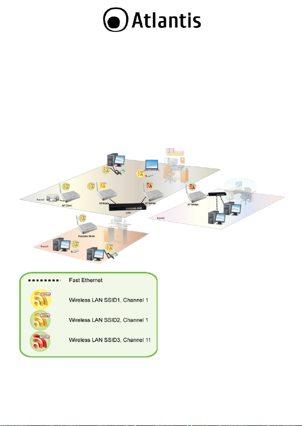
Multi-Function Access Point
The WDS (up to 4 AP) feature makes the device an ideal solution for quickly
creating and extending a wireless local area network (WLAN) in offices or other
workplaces. A pair of Wireless Multi-Function APs operating under Bridge mode to
act as the bridge that connect two Ethernet networks or Ethernet enabled clients
together.
Repeater Mode is able to extend the effective range and coverage of the wireless
network.
Last but not least the AP will be a Wireless Ethernet Adapter transforms any
Ethernet-enabled (Console, Pinter, DLNA player, TV, NAS) devices to have the
wireless function.
When Router function is enabled, it is possible to add between the 2 interfaces,
Wireless and Ethernet, different services (NAT, firewall and QoS).
Virtual AP
The device supports up to 4 SSIDs (client isolation) with VLAN tag that allows
NetFly to perform as multiple virtual access points.
Wall Plug mount and compact size for an easy installation.
10
Page 11

LED
MEANING
PWR
Lit Blue when power is plugged in and the system is
ready.
1.1 System Requirements
Before installing Router, your PC should meet the following:
TCP/IP protocol must be installed on each PC
Web browser, such as Microsoft Internet Explorer 5.0 or later, Netscape
Navigator 6.0 or later
1.2 Package contents
Unpack the package and check all the items carefully. Also, keep the box and
packing materials in case you need to ship the unit in the future. The package
should contain the following items:
NetFly AP4
Power Adapter AC-DC (12V, 1A)
UTP cat. 5 cable (RJ-45 connector), 2 dBi Antenna
Quick Start Guide (English, Italian and French)
Cd-Rom contained manual
Warranty Card & WEEE Disclaimer
If any item contained is damaged or missing, please contact your local
dealer as soon as possible.
1.3 Front LEDs
11
Page 12
LAN
Lit when connected to Ethernet device (Blue for
10/100Mbps)
Blinking when data transmit/received.
WLAN
Flashes when sending/receiving data. Lit blue when the
wireless connection is established
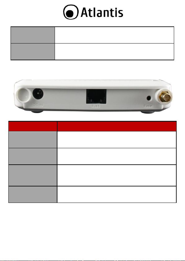
PORT
MEANING
DC-IN
Connect the supplied power adapter to this jack.
RJ45(LAN)
Connect an UTP Ethernet cable to one of the four LAN
ports when connecting to a PC or an office/home network
of 10Mbps or 100Mbps.
Reset
After the device has turned on, press it to reset (10
seconds or above) the device will be restored to factory
default settings (this is used when you can not login to
the router, e.g. forgot the password)
R-SMA
Connect the supplied Antenna here.
1.4 Rear panel and ports
12
Page 13
1.5 Cabling
First you must connect the product to the RJ45 ports the PCs of your Lan or others
Switch. In the end connect the DC Adapter to the socket then to the NetFly AP4.
Once you‟ve done all the connections the product will carry on immediately a
autotest (120 seconds). With the power source on, once the device is connected,
the Power, LAN and WLAN port LEDs will light up indicating a normal status.
If the LAN Port‟s Link indicator does not light up then check the RJ-45 cable if it is
firmly feed to the RJ45 port, while the LAN is link up to the Switch/Hub, the LAN
port‟s LED will light up.
The control LEDs of the device are clearly visible and the status of the network link
can be seen instantly.
1.6 Factory Default Settings
The Wireless Multi-Function Access Point can be configured with your Web browser.
The product provides a very easy and user-friendly interface for configuration.
13
Page 14

When NetFly AP4 works as Access Point/Bridge the IP
192.168.1.1.
This section describes the configuration required by LAN-attached PCs that
communicate with the Wireless Multi-Function Access Point, either to configure the
device or for network access. These PCs must have an Ethernet interface (or
wireless adapter) installed properly, be connected to the Wireless Multi-Function
Access Point either directly or through an external repeater hub or by wireless, and
have TCP/IP installed and configured with a fixed IP address that must be in the
same subnet of the Wireless Multi-Function Access Point. The default IP address of
the Wireless Multi-Function Access Point is 192.168.1.2 and subnet mask is
255.255.255.0. For example, when the default network address of the default IP
address of the AP is 192.168.1.1, then the manager PC should be set at 192.168.1.x
(where x is a number between 5 and 254), and the default subnet mask is
255.255.255.0.
Please follow the steps below for PC‟s network environment installation. First of all,
please check your PC‟s network components. The TCP/IP protocol stack and
Ethernet network adapter must be installed. If not, please refer to MS Windows
related manuals.
Before you configure this Wireless Multi-Function Access Point, you need to know
the following default settings:
Username:admin
Password: atlantis
IP LAN address: (192.168.1.2), Subnet Mask (255.255.255.0)
DHCP Server: disable
Mode: Client Bridge
1.7 TCP/IP Configuration
Windows 2000
Go to Start / Settings / Control Panel. In the Control Panel, double-click
on Network and Dial-up Connections.
Double-click LAN Area Connection.
In the LAN Area Connection Status window, click Properties.
Select Internet Protocol (TCP/IP) and click Properties.
Select Use the Following IP Address (EG IP=192.168.1.5 and subnet
Mask=255.255.255.0).
Click OK to finish the configuration.
14
Page 15

Windows XP
Go to Start / Control Panel (in Classic View). In the Control Panel,
double-click on Network Connections.
Double-click LAN Area Connection.
In the LAN Area Connection Status window, click Properties.
Select Internet Protocol (TCP/IP) and click Properties.
Select Use the Following IP Address (EG IP=192.168.1.5 and subnet
Mask=255.255.255.0).
Click OK to finish the configuration.
Windows VISTA
Go to Start -> Control Panel (in Classic View). In the Control Panel,
double-click on Network and Sharing Center icon.
Click Manage Network connections then double-click Local Area
Connection and click Properties.
Click Continue (Windows needs your permission to continue).
Select Internet Protocol (TCP/IP) and click Properties.
Select Use the Following IP Address (EG IP=192.168.1.5 and subnet
Mask=255.255.255.0).
Click OK to finish the configuration.
Configuring PC (Windows 7)
Go to Start / Control Panel (select Large/Small Icon). In the Control
Panel, double-click on Network and Sharing Center icon.
Click Change Adapter Settings then double-click Local Area Connection
(or Wireless) and click Properties.
Click Continue (Windows needs your permission to continue).
Select Internet Protocol (TCP/IP) and click Properties.
Select Use the Following IP Address (EG IP=192.168.1.5 and subnet
Mask=255.255.255.0).
Click OK to finish the configuration.
15
Page 16
2. Configuring NetFly AP4
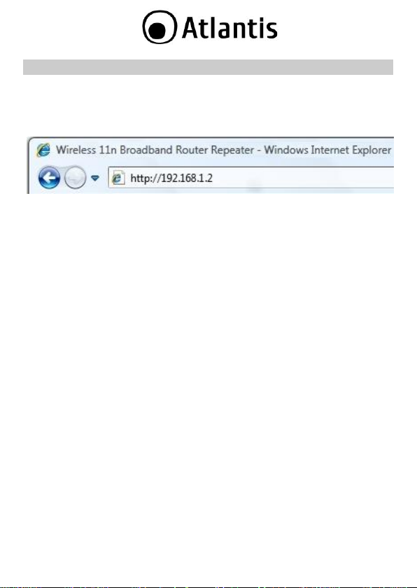
2.1 Browser configuration
Open the web browser, enter the local port IP address of this NetFly AP4, which
default at 192.168.1.2, and click Go to get the login page.
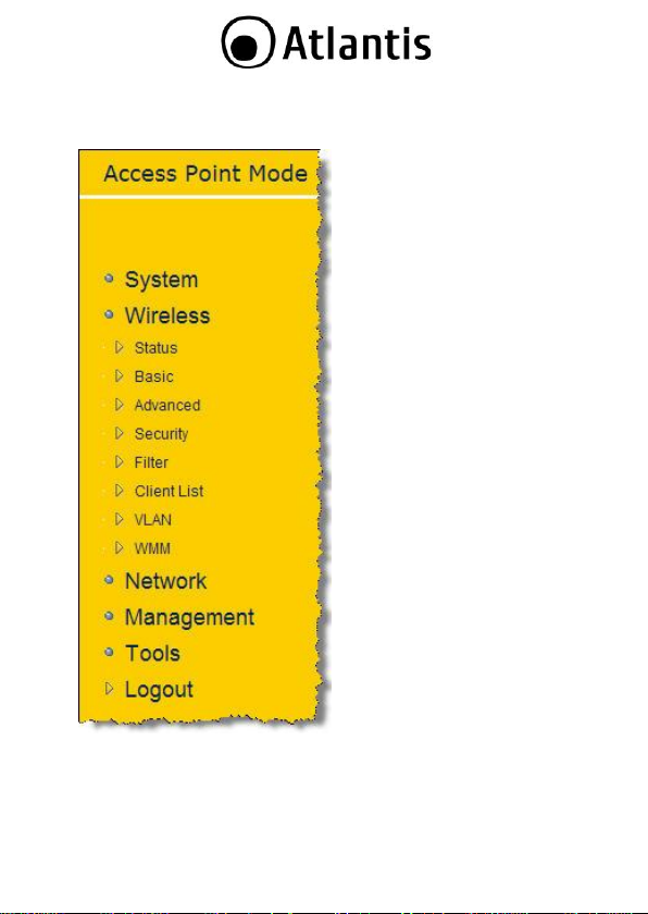
The default username is admin, password atlantis and click OK to continue. At
the configuration homepage, the left navigation pane where bookmarks are
provided links you directly to the desired setup page, including:
System
Wireless
Network
Management
Tools
Logout
Click on the desired item to expand the page with all settings in the main
navigation panel.
16
Page 17
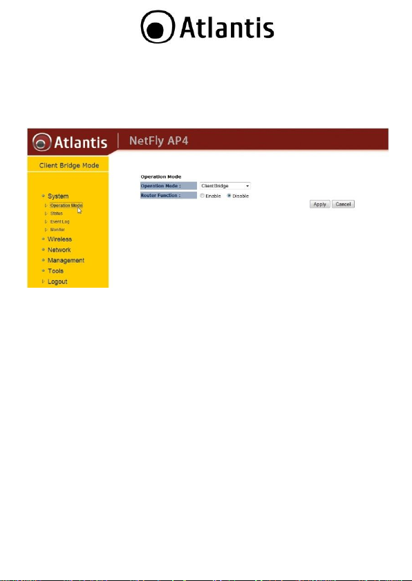
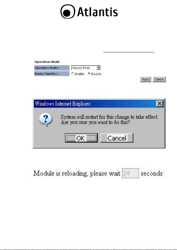
2.2 Switching between Operating Modes
Click on the System link on the navigation drop-down menu. You will then see five
options: Operation Mode, Status, Schedule, Event Log, and Monitor. Click on
Operation Mode. A dialog box will appear to notify you that the system will
restart in order for the change to take effect. Click on the OK button to continue.
Client Wireless (Operation Mode=Client Bridge, Router Function=disable):
transforms any Ethernet-enabled (Console, Pinter, DLNA player, TV, NAS)
devices to have the wireless function.
Client Wireless Router (Operation Mode=Client Bridge, Router
Function=disable): In order to configure NetFly AP4 as a Router, select Access
Client Bridge with Router function from the Operating Mode drop-down list.
Access Point (Operation Mode=Access Point, Router Function=disable): In
order to configure NetFly AP4 as an Access Point, select Access Point from the
Operating Mode drop-down list. IP is 192.168.1.1
Router (Operation Mode=Access Point, Router Function=enable): In order to
configure NetFly AP4 as a Router, select Access Point with Router function
from the Operating Mode drop-down list. IP is 192.168.1.1
WDS Bridge (Operation Mode=WDS Bridge): The WDS (up to 4 AP) feature
makes the device an ideal solution for quickly creating and extending a
wireless local area network (WLAN) in offices or other workplaces. A pair of
Wireless Multi-Function APs operating under Bridge mode to act as the bridge
that connect two Ethernet networks or Ethernet enabled clients together. IP
is 192.168.1.1
Universal Repeater (Operation Mode=Repeater):NetFly AP4 is able to
extend the effective range and coverage of the wireless network.
17
Page 18

A dialog box will appear to notify you that the system will restart in order for the
change to take effect. Click on the OK button to continue
For more detailed instructions on configuring and using the NetFly AP4, please refer
to the online manual into CD.
18
Page 19
3. WEB Configuration
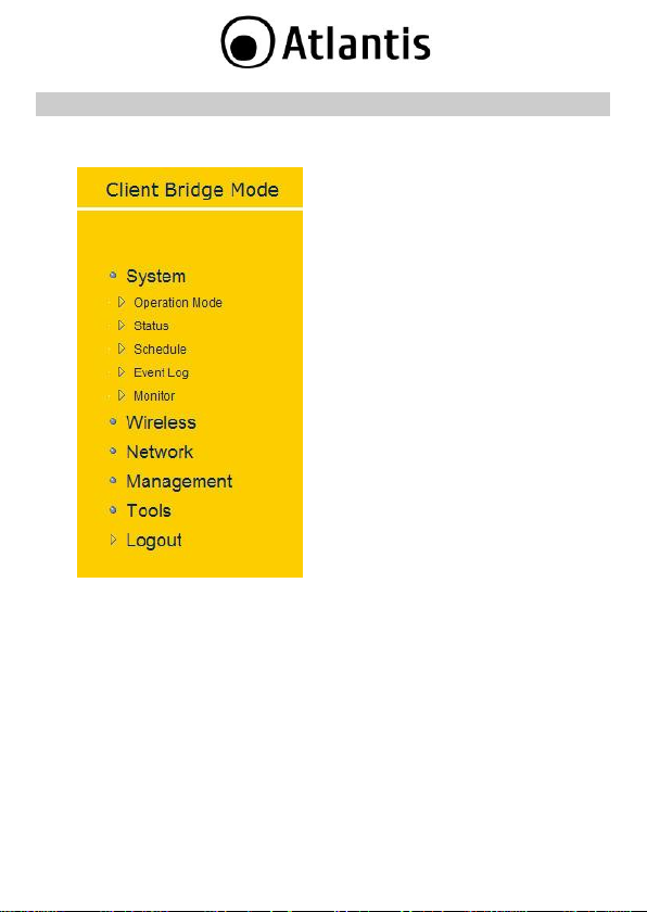
3.1 System
the navigation drop-down menu. You will
then see five options: Operation Mode,
Status, Schedule, Event Log, and Monitor.
Each option is described in detail below.
Click on the System link on
19
Page 20
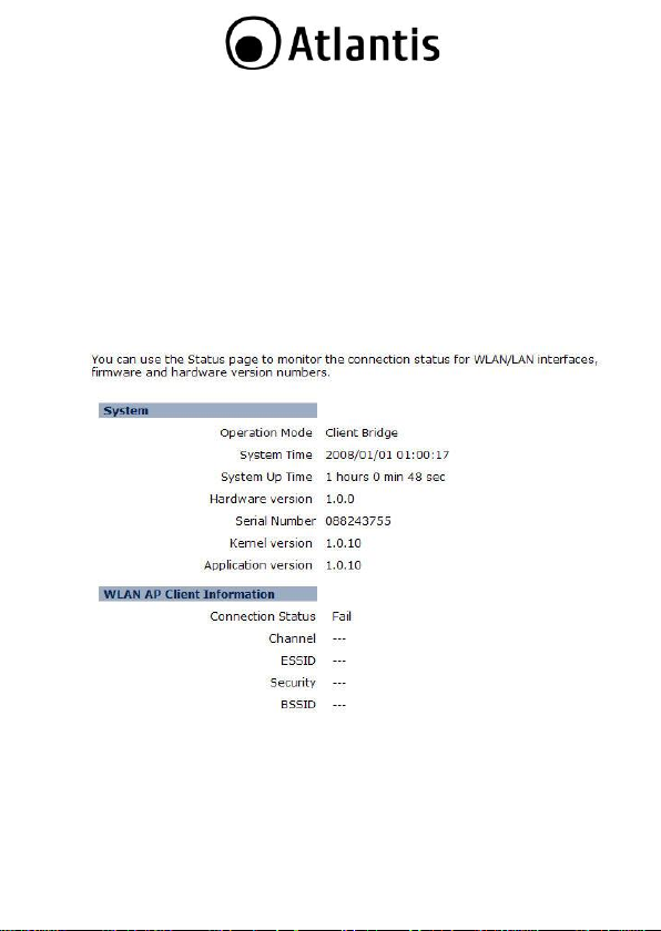
3.1.1 Status
Click on the Status link under the System drop-down menu. The status
page displays a summary of current system settings. Information such
as operating mode, system up time, firmware version, serial number,
kernel version and application version are displayed in the „System‟
section. LAN IP address, subnet mask, and MAC address are displayed in
the „LAN‟ section. In the „WLAN‟ section, the frequency, channel is
displayed. Since this device supports multiple-SSIDs, the details of each
SSID, such as ESSID and its security settings are displayed in the
„SSID_#‟ section.
20
Page 21
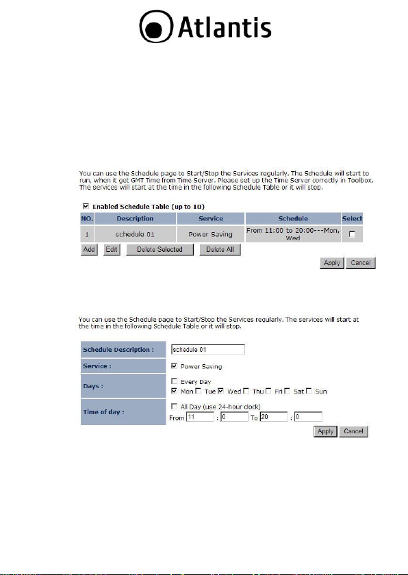
3.1.2 Schedule
Click on the Schedule link in the navigation menu. Prior to setting
schedule, time zone must be set in the Tools menu. Schedules can be
created to specify the occasions to enforce the rules.
For example, if you want enable power saving on Mon-Fri from 3pm to
8pm, you could create a schedule selecting Mon, Tue, Wed, Thu, and Fri
and enter a Start Time of 3pm and End Time of 8pm.
Click on the Add button to add a new schedule. .
Schedule Description: Specify a name for the schedule.
Service: Select a service.
Days: Select the days at which you would like the schedule to be
effective.
Time of Day: Place a check in the All Day box if you would like the
schedule to be active for 24 hours. If you do not use the 24 hours
option, you may specify a start time and end time.
Click on the Apply button to add this schedule into the list.
21
Page 22
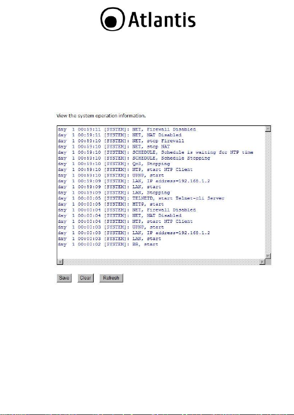
3.1.3 Event Log
Click on the Event Log link on the navigation menu. The device
automatically records important events in its internal memory. Order
records will be over-written by the latest ones when it is out of internal
memory.
Save: Click on the Save button to save the log into a text file on your
computer.
Clear: Click on the Clear button to clear the log on the screen.
Refresh: Click on the Refresh button to refresh the log.
22
Page 23
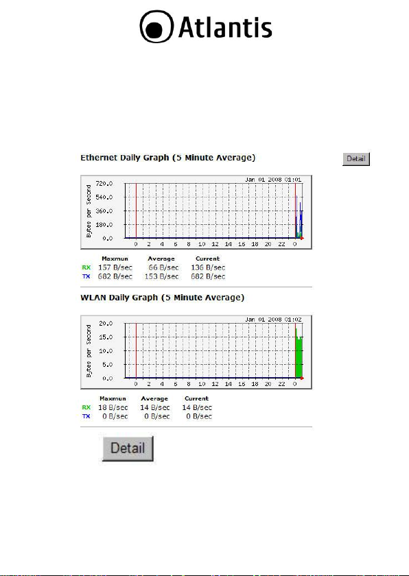
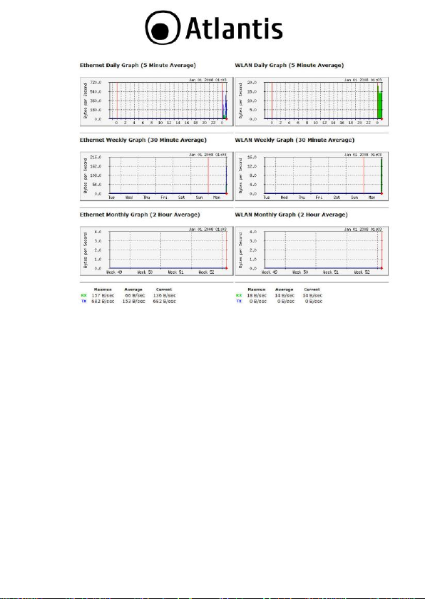
3.1.4 Monitor
Click on the Monitor link in the navigation drop-down menu. This page
displays the transmitted and received packet statistics of the wired (LAN
& WAN) and wireless interface. You may change the auto-refresh time
by selecting the number of seconds from the drop-down list.
Click to view the history records.
23
Page 24
24
Page 25
3.1.4.1 Switching between Operating Modes
Each of the operating modes offers different features. In order to switch
the operating mode, select it from the System >> Operation Mode
A dialog box will appear to notify you that the system will restart in
order for the change to take effect. Click on the OK button to continue.
Please wait while the device counts down and restarts into the new
operating mode.
Each of the operating modes is described in detail in this chapter. Refer
to the following sections for each operating mode:
o 3.2.4.2 Access Point Operating Mode
o 3.2.4.3 Client Bridge Operating Mode
o 3.2.4.4 WDS Bridge Operating Mode
o 3.2.4.5 Repeater Operating Mode
25
Page 26
3.1.4.2 Access Point Operating Mode
In order to configure the
device as an Access Point, select
Access Point from the Operating
Mode drop-down list.
A dialog box will appear to
notify you that the system will restart
in order for the change to take effect.
Click on the OK button to continue.
Please wait while the
device counts down and restarts into
the new operating mode.
Once the device has
restarted into Access Point mode, you
will see a new drop-down menu with
nine options which are: Status, Basic,
Advanced, Security, Filter, WPS,
Client List, VLAN, and WMM. Each of
the options is described in detail
below.
26
Page 27
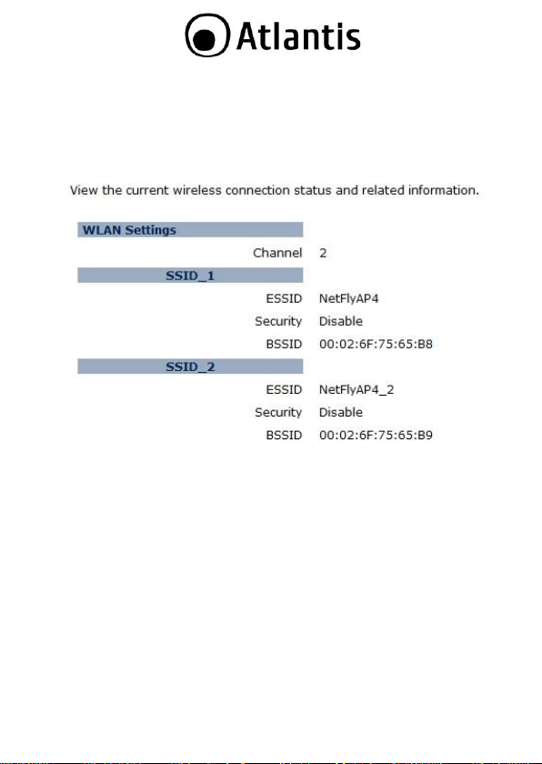
3.1.4.2.1 Status
Click on the Status link under the Wireless drop-down menu. This
page will display the current wireless settings such as SSID, Channel ,
Security and BSSID (MAC address)
27
Page 28

3.1.4.2.2 Basic
Click on the Basic link under the Wireless drop-down menu. This page
will display the current wireless settings such as SSID, Channel, Security
and BSSID (MAC address).
Radio: Choose to Enable or Disable the wireless radio.
Mode: This drop-down list is fixed to AP as this is the Access Point
operating mode.
Band: Select the IEEE 802.11 mode from the drop-down list. For
example, if you are sure that the wireless network will be using only
IEEE 802.11g clients, then it is recommended to select 802.11g only
instead of 2.4 GHz B+G which will reduce the performance of the
wireless network. You may also select 802.11B+G+N. If all of the
wireless devices you want to connect with this router can connect in the
same transmission mode, you can improve performance slightly by
choosing the appropriate "Only" mode. If you have some devices that
use a different transmission mode, choose the appropriate "Mixed"
mode.
ESSID#: This device allows up for four SSIDs, select the SSID# that
you would like to configure from the drop-down list.
28
Page 29

ESSID: The SSID is a unique named shared amongst all the points of
the wireless network. The SSID must be identical on all points of the
wireless network and cannot exceed 32 characters.
Auto Channel: The device can automatically select the clearest channel
in the environment. If auto channel is disabled, then you must select a
channel from the drop-down list.
Channel: Select a channel from the drop-down list. The channels
available are based on the country‟s regulation. A wireless network uses
specific channels in the wireless spectrum to handle communication
between clients. Some channels in your area may have interference
from other electronic devices. Choose the clearest channel to help
optimize the performance and coverage of your wireless network.
Click on the Apply button to save the changes.
29
Page 30

3.1.4.2.3 Advanced
Click on Advanced link under the Wireless drop-down menu. This
page allows you to configure the fragmentation threshold, RTS
threshold, beacon period, transmit power, DTIM Period, etc.
Fragment Threshold: Packets over the specified size will be
fragmented in order to improve performance on noisy networks. Specify
a value between 256 and 2346. The default value is 2346.
RTS Threshold: Packets over the specified size will use the RTS/CTS
mechanism to maintain performance in noisy networks and preventing
hidden nodes from degrading the performance. Specify a value between
0 and 2347. The default value is 2347.
Beacon Period: Beacons are packets sent by a wireless Access Point to
synchronize wireless devices. Specify a Beacon Period value between 20
and 1024. The default value is set to 100 milliseconds.
DTIM Period: A DTIM is a countdown informing clients of the next
window for listening to broadcast and multicast messages. When the
wireless Access Point has buffered broadcast or multicast m essages for
associated clients, it sends the next DTIM with a DTIM Period value.
30
Page 31

Wireless clients detect the beacons and awaken to receive the broadcast
and multicast messages. The default value is 1. Valid settings are
between 1 and 10.
Data Rate: You may select a data rate from the drop-down list,
however, it is recommended to select auto. This is also known as autofallback.
N Data Rate: You may select a data rate for 802.11n from the drop-
down list, however, it is recommended to select auto. This is also
known as auto-fallback.
Channel Bandwidth: You may select a channel bandwidth in order to
improve the efficiency of the network, however, it is recommended to
select Auto 20/40MHz. This is also known as auto-fallback.
Preamble Type: Select a short or long preamble. For optimum
performance it is recommended to also configure the client device as the
same preamble type.
CTS Protection: CTS (Clear to Send) can be always enabled, auto, or
disabled. By enabled CTS, the Access Point and clients will wait for a
„clear‟ signal before transmitting. It is recommended to select auto.
Tx Power: You may control the transmit output power of the device by
selecting a value from the drop-down list. This feature can be helpful in
restricting the coverage area of the wireless network.
Click on the Apply button to save the changes.
31
Page 32

3.1.4.2.4 Wireless Security Mode
Click on the Security link under the Wireless drop-down menu. To
protect your privacy this mode supports several types of wireless
security: WEP WPA, WPA2, and 802.1x RADIUS. WEP is the original
wireless encryption standard. WPA provides a higher level of security.
The following section describes the security configuration in detail.
3.1.4.2.4.1 Security Disabled
Click on the Security link under the Wireless drop-down menu.
ESSID Selection: As this device supports multiple SSIDs, it is possible
to configure a different security mode for each SSID (profile). Select an
SSID from the drop-down list.
Broadcast SSID: Select Enable or Disable from the drop-down list.
This is the SSID broadcast feature. When this option is set to Enable,
your wireless network name is broadcasted of your signal coverage. If
encryption is set to NONE, users will be able to access the AP without
authentication. When this is disabled, you must enter the Wireless
Network Name (SSID) on the client manually to connect to the network.
WMM: Choose to Enable or Disable WMM. This is the Quality of
Service (QoS) feature for prioritizing voice and video applications. This
option can be further configured in WMM under the Wireless dropdown menu.
Encryption: Select Disable from the drop-down list.
Enable 802.1x Authentication: Place a check in this box if you would
like to use RADIUS authentication. This option works with a RADIUS
Server to authenticate wireless clients. Wireless clients should have
32
Page 33

established the necessary credentials before attempting to authenticate
to the Server through this Gateway. Furthermore, it may be necessary to
configure the RADIUS Server to allow this Gateway to authenticate
users. You will then be required to specify the RADIUS Server‟s IP
address, port, and password.
Click on the Apply button to save the changes.
33
Page 34

Click on the Security link under the Wireless drop-down menu.
WEP is an acronym for Wired Equivalent Privacy, and is a security
protocol that provides the same level of security for wireless networks as
for a wired network.
WEP is less secure as compares to WPA encryption. To gain access to a
WEP network, you must know the key. The key is a string of characters
that you use for password. When using WEP, you must determine the
level of encryption.
The type of encryption determines the key length. 128-bit encryption
requires a longer key than 64-bit encryption. Keys are defined by
entering in a string in HEX (hexadecimal - using characters 0-9, A-F) or
ASCII (American Standard Code for Information Interchange alphanumeric characters) format. ASCII format is provided so you can
enter a string that is easier to remember. The ASCII string is converted
to HEX for use over the network. Four keys can be defined so that you
can change keys easily. A default key is automatically generated when
WEP is enabled.
3.1.4.2.4.2 WEP (Wired
Equivalent Privacy)
ESSID Selection: As this device supports multiple SSIDs, it is possible
to configure a different security mode for each SSID (profile). Select an
SSID from the drop-down list.
34
Page 35

Broadcast SSID: Select Enable or Disable from the drop-down list.
This is the SSID broadcast feature. When this option is set to Enable,
your wireless network name is broadcast to anyone within the range of
your signal. If you're not using encryption then they could connect to
your network. When this is disabled, you must enter the Wireless
Network Name (SSID) on the client manually to connect to the network.
WMM: Choose to Enable or Disable WMM. This is the Quality of
Service (QoS) feature for prioritizing voice and video applications. This
option can be further configured in WMM under the Wireless dropdown menu.
Encryption: Select WEP from the drop-down list.
Authentication Type: Select Open System, Shared Key, or auto.
Authentication method from the drop-down list. An open system allows
any client to authenticate as long as it conforms to any MAC address
filter policies that may have been set. All authentication packets are
transmitted without encryption. Shared Key sends an unencrypted
challenge text string to any device attempting to communicate with the
AP. The device requesting authentication encrypts the challenge text
and sends it back to the access point. If the challenge text is encrypted
correctly, the access point allows the requesting device to authenticate.
It is recommended to select Auto if you are not sure which
authentication type is used.
Key Length: Select a 64-bit or 128-bit WEP key length from the
drop-down list.
Key Type: Select a key type from the drop-down list. 128-bit encryption
requires a longer key than 64-bit encryption. Keys are defined by
entering in a string in HEX (hexadecimal - using characters 0-9, A-F) or
ASCII (American Standard Code for Information Interchange alphanumeric characters) format. ASCII format is provided so you can
enter a string that is easier to remember.
Default Key: You may choose one of your 4 different WEP keys from
below.
Encryption Key 1-4: You may enter four different WEP keys.
Enable 802.1x Authentication: Place a check in this box if you would
like to use RADIUS authentication. This option works with a RADIUS
Server to authenticate wireless clients. Wireless clients should have
established the necessary credentials before attempting to authenticate
to the Server through this Gateway. Furthermore, it may be necessary to
configure the RADIUS Server to allow this Gateway to authenticate
users. You will then be required to specify the RADIUS Server‟s IP
address, port, and password.
35
Page 36

Click on the Apply button to save the changes.
36
Page 37

3.1.4.2.4.3 WPA (Wi-Fi
Protected Access) /
Pre-shared Key
Click on the Security link under the Wireless drop-down menu.
WPA (Wi-Fi Protected Access) is designed to improve upon the security
features of WEP (Wired Equivalent Privacy). The technology is designed
to work with existing Wi-Fi products that have been enabled with WEP.
WPA provides improved data encryption through the Temporal Integrity
Protocol (TKIP), which scrambles the keys using a hashing algorithm
and by adding an integrity checking feature which makes sure that keys
haven‟t been tampered with.
ESSID Selection: As this device supports multiple SSIDs, it is possible
to configure a different security mode for each SSID (profile). Select an
SSID from the drop-down list.
Broadcast SSID: Select Enable or Disable from the drop-down list.
This is the SSID broadcast feature. When this option is set to Enable,
your wireless network name is broadcast to anyone within the range of
your signal. If you're not using encryption then they could connect to
your network. When this is disabled, you must enter the Wireless
Network Name (SSID) on the client manually to connect to the network.
WMM: Choose to Enable or Disable WMM. This is the Quality of
Service (QoS) feature for prioritizing voice and video applications. This
option can be further configured in WMM under the Wireless dropdown menu.
Encryption: Select WPA pre-shared key from the drop-down list.
WPA Type: Select TKIP, AES, or WPA2 Mixed. The encryption algorithm
used to secure the data communication. TKIP (Temporal Key Integrity
Protocol) provides per-packet key generation and is based on WEP. AES
(Advanced Encryption Standard) is a very secure block based encryption.
Note that, if the bridge uses the AES option, the bridge can associate
with the access point only if the access point is also set to use only AES.
37
Page 38

Pre-shared Key Type:: The Key Type can be passphrase or Hex
format.
Pre-Shared Key: The key is entered as a pass-phrase of up to 63
alphanumeric characters in ASCII (American Standard Code for
Information Interchange) format at both ends of the wireless
connection. It cannot be shorter than eight characters, although for
proper security it needs to be of ample length and should not be a
commonly known phrase. This phrase is used to generate session keys
that are unique for each wireless client.
Click on the Apply button to save the changes.
38
Page 39

3.1.4.2.4.4 WPA RADIUS
(802.1x)
Click on the Security link under the Wireless drop-down menu.
WPA encryption. WPA (Wi-Fi Protected Access) was designed to improve
upon the security features of WEP (Wired Equivalent Privacy). The
technology is designed to work with existing Wi-Fi products that have
been enabled with WEP. WPA provides improved data encryption
through the Temporal Integrity Protocol (TKIP), which scrambles the
keys using a hashing algorithm and by adding an integrity checking
feature which makes sure that keys haven‟t been tampered with.
This option works with a RADIUS Server to authenticate wireless clients.
Wireless clients should have established the necessary credentials before
attempting to authenticate to the Server through this Gateway.
Furthermore, it may be necessary to configure the RADIUS Server to
allow this Gateway to authenticate users.
ESSID Selection: As this device supports multiple SSIDs, it is possible
to configure a different security mode for each SSID (profile). Select an
SSID from the drop-down list.
Broadcast SSID: Select Enable or Disable from the drop-down list.
This is the SSID broadcast feature. When this option is set to Enable,
your wireless network name is broadcast to anyone within the range of
your signal. If you're not using encryption then they could connect to
your network. When this is disabled, you must enter the Wireless
Network Name (SSID) on the client manually to connect to the network.
WMM: Choose to Enable or Disable WMM. This is the Quality of
Service (QoS) feature for prioritizing voice and video applications. This
option can be further configured in WMM under the Wireless dropdown menu.
Encryption: Select WPA RADIUS from the drop-down list.
39
Page 40

WPA Type: Select TKIP, AES, or WPA2 Mixed. The encryption algorithm
used to secure the data communication. TKIP (Temporal Key Integrity
Protocol) provides per-packet key generation and is based on WEP. AES
(Advanced Encryption Standard) is a very secure block based encryption.
Note that, if the bridge uses the AES option, the bridge can associate
with the access point only if the access point is also set to use only AES.
RADIUS Server IP Address: Specify the IP address of the RADIUS
server.
RADIUS Server Port: Specify the port number of the RADIUS server,
the default port is 1812.
RADIUS Server Password: Specify the pass-phrase that is matched
on the RADIUS Server.
Click on the Apply button to save the changes.
40
Page 41

3.1.4.2.5 Filter
You will be able to block out connections from unauthorized MAC
Address by setting filter policy.
Check on the Enable Wireless MAC Filtering
Type in Description as a note for your own reference
Enter the MAC address that you allow for accessing to your device
Press Add to apply the policy
Click Apply for the setting to take effect
41
Page 42

3.1.4.2.6 Client List
Click on the Client List link under the Wireless drop-down menu. This
page displays the list of Clients that are associated to the Access Point.
The MAC address and signal strength for each client is displayed. Click
on the Refresh button to refresh the client list
42
Page 43

3.1.4.2.7 VLAN
Click on the VLAN link under the Wireless drop-down menu. A VLAN
(Virtual LAN) is a group of hosts with a common set of requirements
that communicate as if they were attached to the same wire, regardless
of their physical location.
Virtual LAN: Choose to Enable or Disable the VLAN features.
SSID1 Tag: Specify the VLAN tag.
Click on the Apply button to save the changes.
3.1.4.2.8 WMM (Wireless Multimedia)
Click on the WMM link under the Wireless drop-down menu. WMM is
Quality of Service (QoS) for wireless and ensures that voice and video
applications get priority in order to run smoothly.
Specify the priority and then click on the Apply button.
43
Page 44

3.1.4.3 Client Bridge Operating Mode
In order to configure the device as an Access Point, select Client
Bridge from the Operating Mode drop-down list.
A dialog box will appear to notify you that the system will restart in
order for the change to take effect. Click on the OK button to continue.
Please wait while the device counts down and restarts into the new
operating mode.
Once the device has restarted into Client Bridge mode, you will see a
new drop-down menu with fice options which are: Status, Basic,
Advanced, AP Profile, and WMM. Each of the options is described in
detail below.
44
Page 45

3.1.4.3.1 Status
Click on the Status link under the Wireless drop-down menu. This
page will display the current wireless settings such as SSID, Channel ,
Security and BSSID (MAC address)
3.1.4.3.2 Basic
Click on the Basic link under the Wireless drop-down menu. This page
will display the current wireless settings such as SSID, Channel, Security
and BSSID (MAC address).
Radio: Choose to Enable or Disable the wireless radio.
Mode: This drop-down list is fixed to Client as this is the Client Bridge
operating mode.
45
Page 46

Band: Select the IEEE 802.11 mode from the drop-down list. For
example, if you are sure that the wireless network will be using only
IEEE 802.11g clients, then it is recommended to select 802.11g only
instead of 2.4 GHz B+G which will reduce the performance of the
wireless network. You may also select 802.11B+G+N. If all of the
wireless devices you want to connect with this router can connect in the
same transmission mode, you can improve performance slightly by
choosing the appropriate "Only" mode. If you have some devices that
use a different transmission mode, choose the appropriate "Mixed"
mode.
Site Survey: Click on the Site Survey button to view a list of Access
Points in the area. The Site Survey page displays information about
devices within the 802.11b/g/n frequency. Information such as channel,
SSID, BSSID, encryption, authentication, signal strength, and operating
mode are displayed. Select the desired device and then click on the Add
to AP Profile button.
SSID: The SSID is a unique named shared amongst all the points of the
wireless network. The SSID must be identical on all points of the
wireless network and cannot exceed 32 characters.
Status: Displays the current status of the device.
Channel: The channels available are based on the country‟s regulation.
A wireless network uses specific channels in the wireless spectrum to
handle communication between clients. Some channels in your area may
have interference from other electronic devices.
Click on the Apply button to save the changes.
46
Page 47

3.1.4.3.3 Advanced
Click on Advanced link under the Wireless drop-down menu. This
page allows you to configure the fragmentation threshold, RTS
threshold, beacon period, transmit power, DTIM Period, etc.
Fragment Threshold: Packets over the specified size will be
fragmented in order to improve performance on noisy networks. Specify
a value between 256 and 2346. The default value is 2346.
RTS Threshold: Packets over the specified size will use the RTS/CTS
mechanism to maintain performance in noisy networks and preventing
hidden nodes from degrading the performance. Specify a value between
0 and 2347. The default value is 2347.
Beacon Period: Beacons are packets sent by a wireless Access Point to
synchronize wireless devices. Specify a Beacon Period value between 20
and 1024. The default value is set to 100 milliseconds.
DTIM Period: A DTIM is a countdown informing clients of the next
window for listening to broadcast and multicast messages. When the
wireless Access Point has buffered broadcast or multicast messages for
associated clients, it sends the next DTIM with a DTIM Period value.
Wireless clients detect the beacons and awaken to receive the broadcast
and multicast messages. The default value is 1. Valid settings are
between 1 and 10.
Data Rate: You may select a data rate from the drop-down list,
however, it is recommended to select auto. This is also known as autofallback.
47
Page 48

N Data Rate: You may select a data rate for 802.11n from the drop-
down list, however, it is recommended to select auto. This is also
known as auto-fallback.
Preamble Type: Select a short or long preamble. For optimum
performance it is recommended to also configure the client device as the
same preamble type.
Click on the Apply button to save the changes.
Click on the AP Profile link under the Wireless drop-down menu.
This page allows you to configure the profile of the Client Bridge
including Security Setting exactly the same as the Access Point.
3.1.4.3.4 AP Profile
3.1.4.3.4.1 Manage AP Profile
1. Press Add/Edit to add/modify the SSID(s) of your device.
2. Setting Encryption type from Encryption dropdown list. (See
3.2.4.2.4.2 to 3.2.4.2.4.4)
3. Press Save to save your setting.
4. Check one of the SSID in the table to Move Up or Move Down
the display order
48
Page 49

5. Delete Selected to delete the SSID on check.
6. Delete All to delete all SSID from the table
7. Connect to configure your device using the SSID on check
3.1.4.3.5 WMM (Wireless Multimedia)
Click on the WMM link under the Wireless drop-down menu. WMM is
Quality of Service (QoS) for wireless and ensures that voice and video
applications get priority in order to run smoothly.
Specify the priority and then click on the Apply button.
49
Page 50

3.1.4.4 WDS Operating Mode
In order to configure the device as an Access Point, select WDS from
the Operating Mode drop-down list.
A dialog box will appear to notify you that the system will restart in
order for the change to take effect. Click on the OK button to continue.
Please wait while the device counts down and restarts into the new
operating mode.
Once the device has restarted into WDS mode, you will see a new drop-
down menu with four options which are: Status, Basic, Advanced, and
WMM. Each of the options is described in detail below.
50
Page 51

3.1.4.4.1 Status
Click on the Status link under the Wireless drop-down menu. This
page will display the current wireless settings such as SSID, Channel ,
Security and BSSID (MAC address)
3.1.4.4.2 Basic
Click on the Basic link under the Wireless drop-down menu. This page
will display the current wireless settings such as SSID, Channel, Security
and BSSID (MAC address).
51
Page 52

Radio: Choose to Enable or Disable the wireless radio.
Mode: This drop-down list is fixed to WDS as this is the Wireless
Distribution operating mode.
Band: Select the IEEE 802.11 mode from the drop-down list. For
example, if you are sure that the wireless network will be using only
IEEE 802.11g clients, then it is recommended to select 802.11g only
instead of 2.4 GHz B+G which will reduce the performance of the
wireless network. You may also select 802.11B+G+N. If all of the
wireless devices you want to connect with this router can connect in the
same transmission mode, you can improve performance slightly by
choosing the appropriate "Only" mode. If you have some devices that
use a different transmission mode, choose the appropriate "Mixed"
mode.
Channel: Select a channel from the drop-down list. The channels
available are based on the country‟s regulation. A wireless network uses
specific channels in the wireless spectrum to handle communication
between clients. Some channels in your area may have interference
from other electronic devices. Choose the clearest channel to help
optimize the performance and coverage of your wireless network.
52
Page 53

MAC Address #: Specify the MAC address (BSSID) of up to four
devices within the WDS.
Set Security: Setting data encryption type. (See 3.2.4.2.4.2 to
3.2.4.2.4.4)
Click on the Apply button to save the changes.
53
Page 54

3.1.4.4.3 Advanced
Click on Advanced link under the Wireless drop-down menu. This
page allows you to configure the fragmentation threshold, RTS
threshold, beacon period, transmit power, DTIM Period, etc.
Fragment Threshold: Packets over the specified size will be
fragmented in order to improve performance on noisy networks. Specify
a value between 256 and 2346. The default value is 2346.
RTS Threshold: Packets over the specified size will use the RTS/CTS
mechanism to maintain performance in noisy networks and preventing
hidden nodes from degrading the performance. Specify a value between
0 and 2347. The default value is 2347.
Beacon Interval: Beacons are packets sent by a wireless Access Point
to synchronize wireless devices. Specify a Beacon Period value between
20 and 1024. The default value is set to 100 milliseconds.
DTIM Period: A DTIM is a countdown informing clients of the next
window for listening to broadcast and multicast messages. When the
wireless Access Point has buffered broadcast or multicast messages for
associated clients, it sends the next DTIM with a DTIM Period value.
Wireless clients detect the beacons and awaken to receive the broadcast
and multicast messages. The default value is 1. Valid settings are
between 1 and 10.
54
Page 55

Data Rate: You may select a data rate from the drop-down list,
however, it is recommended to select auto. This is also known as autofallback.
N Data Rate: You may select a data rate for 802.11n from the drop-
down list, however, it is recommended to select auto. This is also
known as auto-fallback.
Channel Bandwidth: You may select a channel bandwidth in order to
improve the efficiency of the network, however, it is recommended to
select Auto 20/40MHz. This is also known as auto-fallback.
Preamble Type: Select a short or long preamble. For optimum
performance it is recommended to also configure the client device as the
same preamble type.
CTS Protection: CTS (Clear to Send) can be always enabled, auto, or
disabled. By enabled CTS, the Access Point and clients will wait for a
„clear‟ signal before transmitting. It is recommended to select auto.
Tx Power: You may control the transmit output power of the device by
selecting a value from the drop-down list. This feature can be helpful in
restricting the coverage area of the wireless network.
Click on the Apply button to save the changes.
Click on the WMM link under the Wireless drop-down menu. WMM is
Quality of Service (QoS) for wireless and ensures that voice and video
applications get priority in order to run smoothly.
Specify the priority and then click on the Apply button.
3.1.4.4.4 WMM (Wireless Multimedia)
55
Page 56

56
Page 57

3.1.4.5 Repeater Operating Mode
In order to
configure the device as an
Access Point, select
Repeater from the
Operating Mode dropdown list.
A dialog box
will appear to notify you
that the system will restart
in order for the change to
take effect. Click on the
OK button to continue.
Please wait
while the device counts
down and restarts into the
new operating mode.
Once the
device has restarted into
Repeater mode, you will
see a new drop-down
menu with eight options
which are: Status, Basic,
Advanced, Security, Filter,
WPS, Client List, and
WMM. Each of the options
is described in detail
below.
57
Page 58

3.1.4.5.1 Status
Click on the Status link under the Wireless drop-down menu. This
page will display the current wireless settings such as SSID, Channel ,
Security and BSSID (MAC address)
3.1.4.5.2 Basic
Click on the Basic link under the Wireless drop-down menu. This page
will display the current wireless settings such as SSID, Channel, Security
and BSSID (MAC address).
Radio: Choose to Enable or Disable the wireless radio.
Mode: This drop-down list is fixed to WDS as this is the Wireless
Distribution operating mode.
Band: Select the IEEE 802.11 mode from the drop-down list. For
example, if you are sure that the wireless network will be using only
IEEE 802.11g clients, then it is recommended to select 802.11g only
instead of 2.4 GHz B+G which will reduce the performance of the
wireless network. You may also select 802.11B+G+N. If all of the
wireless devices you want to connect with this router can connect in the
same transmission mode, you can improve performance slightly by
choosing the appropriate "Only" mode. If you have some devices that
use a different transmission mode, choose the appropriate "Mixed"
58
Page 59

mode.
ESSID#: This device allows up for four SSIDs, select the SSID# that
you would like to configure from the drop-down list.
ESSID: The SSID is a unique named shared amongst all the points of
the wireless network. The SSID must be identical on all points of the
wireless network and cannot exceed 32 characters.
Channel: Select the channel as you wish to use for your device
Click on the Apply button to save the changes.
59
Page 60

Site Survey: Click on the Site Survey button to view a list of Access
Points in the area. The Site Survey page displays information about
devices within the 802.11b/g/n frequency. Information such as channel,
SSID, BSSID, encryption, authentication, signal strength, and operating
mode are displayed. Select the desired device and then click on the
Connect button.
SSID: The SSID is a unique named shared amongst all the points of the
wireless network. The SSID must be identical on all points of the
wireless network and cannot exceed 32 characters.
Status: Displays the current status of the device.
Channel: The channels available are based on the country‟s regulation.
A wireless network uses specific channels in the wireless spectrum to
handle communication between clients. Some channels in your area may
have interference from other electronic devices.
Click on the Apply button to save the changes.
60
Page 61

Click on Advanced link under the Wireless drop-down menu. This
page allows you to configure the fragmentation threshold, RTS
threshold, beacon period, transmit power, DTIM Period, etc.
3.1.4.5.3 Advanced
Fragment Threshold: Packets over the specified size will be
fragmented in order to improve performance on noisy networks. Specify
a value between 256 and 2346. The default value is 2346.
RTS Threshold: Packets over the specified size will use the RTS/CTS
mechanism to maintain performance in noisy networks and preventing
hidden nodes from degrading the performance. Specify a value between
0 and 2347. The default value is 2346.
Beacon Interval: Beacons are packets sent by a wireless Access Point
to synchronize wireless devices. Specify a Beacon Period value between
20 and 1000. The default value is set to 100 milliseconds.
DITM Period: A DTIM is a countdown informing clients of the next
window for listening to broadcast and multicast messages. When the
wireless Access Point has buffered broadcast or multicast messages for
associated clients, it sends the next DTIM with a DTIM Period value.
Wireless clients detect the beacons and awaken to receive the broadcast
61
Page 62

and multicast messages. The default value is 1. Valid settings are
between 1 and 10.
Data Rate: You may select a data rate from the drop-down list,
however, it is recommended to select auto. This is also known as autofallback.
N Data Rate: You may select a data rate for 802.11n from the drop-
down list, however, it is recommended to select auto. This is also
known as auto-fallback.
Channel Bandwidth: You may select a channel bandwidth in order to
improve the efficiency of the network, however, it is recommended to
select Auto 20/40MHz. This is also known as auto-fallback.
Preamble Type: Select a short or long preamble. For optimum
performance it is recommended to also configure the client device as the
same preamble type.
CTS Protection: CTS (Clear to Send) can be always enabled, auto, or
disabled. By enabled CTS, the Access Point and clients will will wait for a
„clear‟ signal before transmitting. It is recommended to select auto.
Tx Power: You may control the transmit output power of the device by
selecting a value from the drop-down list. This feature can be helpful in
restricting the coverage area of the wireless network.
Click on the Apply button to save the changes.
62
Page 63

3.1.4.5.4 Wireless Security Mode
Click on the Security link under the Wireless drop-down menu. To
protect your privacy this mode supports several types of wireless
security: WEP WPA, WPA2, and 802.1x RADIUS. WEP is the original
wireless encryption standard. WPA provides a higher level of security.
The following section describes the security configuration in detail.
3.1.4.5.4.1 Security Disabled
Click on the Security link under the Wireless drop-down menu.
ESSID Selection: As this device supports multiple SSIDs, it is possible
to configure a different security mode for each SSID (profile). Select an
SSID from the drop-down list.
Broadcast SSID: Select Enable or Disable from the drop-down list.
This is the SSID broadcast feature. When this option is set to Enable,
your wireless network name is broadcast to anyone within the range of
your signal. If you're not using encryption then they could connect to
your network. When this is disabled, you must enter the Wireless
Network Name (SSID) on the client manually to connect to the network.
WMM: Choose to Enable or Disable WMM. This is the Quality of
Service (QoS) feature for prioritizing voice and video applications. This
option can be further configured in WMM under the Wireless dropdown menu.
Encryption: Select Disable from the drop-down list.
Click on the Apply button to save the changes.
63
Page 64

Click on the Security link under the Wireless drop-down menu.
WEP is an acronym for Wired Equivalent Privacy, and is a security
protocol that provides the same level of security for wireless networks as
for a wired network.
WEP is less secure as compares to WPA encryption. To gain access to a
WEP network, you must know the key. The key is a string of characters
that you use for password. When using WEP, you must determine the
level of encryption.
The type of encryption determines the key length. 128-bit encryption
requires a longer key than 64-bit encryption. Keys are defined by
entering in a string in HEX (hexadecimal - using characters 0-9, A-F) or
ASCII (American Standard Code for Information Interchange alphanumeric characters) format. ASCII format is provided so you can
enter a string that is easier to remember. The ASCII string is converted
to HEX for use over the network. Four keys can be defined so that you
can change keys easily. A default key is automatically generated when
WEP is enabled.
3.1.4.5.4.2 WEP (Wired
Equivalent Privacy)
ESSID Selection: As this device supports multiple SSIDs, it is possible
to configure a different security mode for each SSID (profile). Select an
SSID from the drop-down list.
Broadcast SSID: Select Enable or Disable from the drop-down list.
This is the SSID broadcast feature. When this option is set to Enable,
64
Page 65

your wireless network name is broadcast to anyone within the range of
your signal. If you're not using encryption then they could connect to
your network. When this is disabled, you must enter the Wireless
Network Name (SSID) on the client manually to connect to the network.
WMM: Choose to Enable or Disable WMM. This is the Quality of
Service (QoS) feature for prioritizing voice and video applications. This
option can be further configured in WMM under the Wireless dropdown menu.
Encryption: Select WEP from the drop-down list.
Authentication Type: Select Open System, Shared Key, or auto.
Authentication method from the drop-down list. An open system allows
any client to authenticate as long as it conforms to any MAC address
filter policies that may have been set. All authentication packets are
transmitted without encryption. Shared Key sends an unencrypted
challenge text string to any device attempting to communicate with the
AP. The device requesting authentication encrypts the challenge text
and sends it back to the access point. If the challenge text is encrypted
correctly, the access point allows the requesting device to authenticate.
It is recommended to select Auto if you are not sure which
authentication type is used.
Key Length: Select a 64-bit or 128-bit WEP key length from the
drop-down list.
Key Type: Select a key type from the drop-down list. 128-bit encryption
requires a longer key than 64-bit encryption. Keys are defined by
entering in a string in HEX (hexadecimal - using characters 0-9, A-F) or
ASCII (American Standard Code for Information Interchange alphanumeric characters) format. ASCII format is provided so you can
enter a string that is easier to remember.
Default Key: You may choose one of your 4 different WEP keys from
below.
Encryption Key 1-4: You may enter four different WEP keys.
Enable 802.1x Authentication: Place a check in this box if you would
like to use RADIUS authentication. This option works with a RADIUS
Server to authenticate wireless clients. Wireless clients should have
established the necessary credentials before attempting to authenticate
to the Server through this Gateway. Furthermore, it may be necessary to
configure the RADIUS Server to allow this Gateway to authenticate
users. You will then be required to specify the RADIUS Server‟s IP
address, port, and password.
Click on the Apply button to save the changes.
65
Page 66

3.1.4.5.4.3 WPA (Wi-Fi
Protected Access) /
Pre-shared Key
Click on the Security link under the Wireless drop-down menu.
WPA (Wi-Fi Protected Access) is designed to improve upon the security
features of WEP (Wired Equivalent Privacy). The technology is designed
to work with existing Wi-Fi products that have been enabled with WEP.
WPA provides improved data encryption through the Temporal Integrity
Protocol (TKIP), which scrambles the keys using a hashing algorithm
and by adding an integrity checking feature which makes sure that keys
haven‟t been tampered with.
ESSID Selection: As this device supports multiple SSIDs, it is possible
to configure a different security mode for each SSID (profile). Select an
SSID from the drop-down list.
Broadcast SSID: Select Enable or Disable from the drop-down list.
This is the SSID broadcast feature. When this option is set to Enable,
your wireless network name is broadcast to anyone within the range of
your signal. If you're not using encryption then they could connect to
your network. When this is disabled, you must enter the Wireless
Network Name (SSID) on the client manually to connect to the network.
WMM: Choose to Enable or Disable WMM. This is the Quality of
Service (QoS) feature for prioritizing voice and video applications. This
option can be further configured in WMM under the Wireless dropdown menu.
Encryption: Select WPA pre-shared key from the drop-down list.
WPA Type: Select TKIP, AES, or WPA2 Mixed. The encryption algorithm
used to secure the data communication. TKIP (Temporal Key Integrity
Protocol) provides per-packet key generation and is based on WEP. AES
(Advanced Encryption Standard) is a very secure block based encryption.
Note that, if the bridge uses the AES option, the bridge can associate
with the access point only if the access point is also set to use only AES.
66
Page 67

Pre-shared Key Type:: The Key Type can be passphrase or Hex
format.
Pre-Shared Key: The key is entered as a pass-phrase of up to 63
alphanumeric characters in ASCII (American Standard Code for
Information Interchange) format at both ends of the wireless
connection. It cannot be shorter than eight characters, although for
proper security it needs to be of ample length and should not be a
commonly known phrase. This phrase is used to generate session keys
that are unique for each wireless client.
Click on the Apply button to save the changes.
67
Page 68

3.1.4.5.5 Filter
You will be able to block out connections from unauthorized MAC
Address by setting filter policy.
Check on the Enable Wireless MAC Filtering
Type in Description as a note for your own reference
Enter the MAC address that you allow for accessing to your device
Press Add to apply the policy
Click Apply for the setting to take effect
68
Page 69

3.1.4.5.6 Client List
Click on the Client List link under the Wireless drop-down menu. This
page displays the list of Clients that are associated to the device.
The MAC address and signal strength for each client is displayed. Click
on the Refresh button to refresh the client list
3.1.4.5.7 WMM (Wireless Multimedia)
Click on the WMM link under the Wireless drop-down menu. WMM is
Quality of Service (QoS) for wireless and ensures that voice and video
applications get priority in order to run smoothly.
Specify the priority and then click on the Apply button.
69
Page 70

3.2 Network
Click on the Network link on the navigation drop-down menu. You will
then see three options: Status, LAN, and WAN. Each option is described
in detail below.
3.2.1 Status
Click on the Status link on the Network navigation drop-down menu.
This page will display the current LAN settings such as IP address,
subnet mask, and MAC address.
3.2.2 LAN / DHCP Client, Server
Click on the LAN link on the Network navigation drop-down menu.
This page will allow you to configure the device as a static or dynamic IP
address, along with DHCP server settings.
Bridge Type: Select Static IP or Dynamic IP from the drop-down
list. If you select Static IP, you will be required to specify an IP address
70
Page 71

and subnet mask. If Dynamic IP is selected, then the IP address is
received automatically from the external DHCP server.
IP Address: Specify an IP address.
IP Subnet Mask: Specify a subnet mask for the IP address.
802.1d Spanning Tree: Select Enable or Disable from the drop-
down list. Enabling spanning tree will avoid redundant data loops.
DHCP Server: Select Enable or Disable from the drop-down list. If
this is enabled, you will be required to specify the lease time, start and
end IP address range, and domain name. If DHCP server is disabled,
then all the clients connected to this device will need to acquire an IP
address from the DHCP server behind this device.
Lease Time: Select a lease time from the drop-down list.
Start IP: Specify the starting IP address for the DHCP server to assign
IP addresses.
End IP: Specify the last IP address for the DHCP server to end
assigning IP addresses.
Domain Name: Specify a domain name.
Click on the Apply button to save the changes.
71
Page 72

3.3 Management
Click on the Management link on the navigation drop-down menu. You
will then see four options: Admin, SNMP, Firmware, and Configure. Each
option is described in detail below.
3.3.1 Admin
Click on the Admin link on the Management navigation drop-down
menu. This page allows you to configure a new password to login to the
device. It is recommended to change the default password for security
reasons.
Old Password: Specify the old password of the device.
New Password: Specify a new password.
Repeat New Password: Re-type the new password.
Click on the Apply button to save the changes.
72
Page 73

3.3.2 SNMP
Click on the SNMP link on the Management navigation drop-down
menu. This option allows you to assign the contact details, location,
community name and trap settings for SNMP. This is a networking
management protocol used to monitor network-attached devices. SNMP
allows messages (called protocol data units) to be sent to various parts
of a network. Upon receiving these messages, SNMP-compatible devices
(called agents) return data stored in their Management Information
Bases. .
SNMP Active: Choose to enable or disable the SNMP feature.
SNMP Version: You may select a specific version or select All from the
drop-down list.
Read Community Name: Specify the password for access the SNMP
community for read only access.
Set Community Name: Specify the password for access to the SNMP
community with read/write access.
System Location: Specify the location of the device.
System Contact: Specify the contact details of the device.
Send SNMP Trap: Specify the IP address of the computer that will
receive the SNMP traps.
73
Page 74

Trap Active: Choose to enable or disable the SNMP trapping feature.
.
Trap Manager IP: Specify the password for the SNMP trap community.
Click on the Apply button to save the changes.
3.3.3 Firmware Upgrade
Click on the Firmware link in the navigation menu. This page allows
you to upgrade the firmware of the device in order to improve the
functionality and performance.
Ensure that you have downloaded the appropriate firmware from the
vendor‟s website. Connect the device to your PC using an Ethernet
cable, as the firmware cannot be upgraded using the wireless interface.
Click on the Browse button to select the firmware and then click on the
Apply button.
74
Page 75

3.3.4 Restore to Factory Default
Click on the Configure link in the navigation menu
Click on the Reset button to reset the device to the factory default
settings.
Once the dialog box appears, click on the OK button to confirm the
action.
Note: The current settings will be lost.
Click on the OK button to continue. You will then see the Rebooting
page.
Please wait while the system is rebooting.
Note: Do no un-plug the device during this process as this may cause
permanent damage.
75
Page 76

3.3.5 Backup Settings
Click on the Configure link in the navigation menu
Click on the Save button you will be provided with download link
Click on download link to save file to your local disk.
3.3.6 Restore Settings
Click on the Configure link in the navigation menu
Click on the Browse button to select the file that has been backed up
and then click on the Upload button.
3.3.7 Reset
Press Apply to reset your device.
76
Page 77

3.4 Tools
Click on the Tools link on the navigation drop-down menu. You will then
see four options: Time zone, power saving, diagnosis, and reset. Each
option is described in detail below.
3.4.1 Time Setting
Click on the Time Setting link in the navigation menu. This feature
allows you to configure, update, and maintain the correct time on the
device‟s internal system clock as well as configure the time zone. The
date and time of the device can be configured manually or by
synchronizing with a time server.
Note: If the device losses power for any reason, it will not be able to
keep its clock running, and will not display the correct time once the
device has been restarted. Therefore, you must re-enter the correct date
and time.
Time Zone: Select your time zone from the drop-down list.
NTP Time Server: Specify the NTP server‟s IP address to synchronize
the device‟s clock to a Network Time Server over the Internet.
Daylight Saving: Place a check in this box to enable daylight savings
time. And select the date/time from the drop-down list.
Click on the Apply button to save the changes.
77
Page 78

3.4.2 Diagnosis
Click on the Diagnosis link in the navigation menu. This page allows to
Ping a device to check if it is active.
Address to Ping: Specify the IP address to ping and then click on the
Start button. The result will then display in the field below.
78
Page 79

4. Support
For technical questions and support, please contact our help-desk by ticket on
http://www.atlantis-land.com/ita/supporto.php.
For generic informations, please send an e-mail to info@atlantis-land.com.
For presales informations, please send an e-mail to prevendite@atlantis-land.com.
Atlantis SpA
Via S. Antonio, 8/10
20020 Lainate (MI)
Fax: +39.02.78.62.64.39
Website: http://www.atlantis-land.com
Email: info@atlantis-land.com
79
Page 80

Steps
Corrective Action
1
Make sure that the NetFlu AP4 WN is connected to an appropriate
power source.
2
Verify that AC Adapter is well connected.
4
If the error persists, you may have a hardware problem. In this
case, you should contact your vendor.
Steps
Corrective Action
1
Check the Ethernet cable connections between the device and the
computer or hub.
2
Check for faulty Ethernet cables.
3
Make sure your computer‟s Ethernet card is working properly.
4
If these steps fail to correct the problem, contact your local
distributor for assistance.
Steps
Corrective Action
1
Make sure you are using the correct IP address of the device.
Check the IP address of the NetFly AP4 WN.
2
Make sure that there is not an console session running.
3
Check that you have enabled web service access. If you have
configured a secured client IP address, your computer‟s IP
address must match it. Refer to the chapter on remote
APPENDIX A: Troubleshooting
This chapter covers potential problems and the corresponding remedies.
A.1 Using LEDs to diagnose problems
The LEDs are useful aides for finding possible problem causes.
A.1.1 Power LED
The PWR LED on the front panel does not light up.
A.1.2 LAN LED
The LAN LED on the front panel does not light up.
A.2 WEB Configurator
I cannot access the web configurator.
80
Page 81

management for details.
6
If you changed the NetFly LAN IP address, then enter the new
one as the URL.
Steps
Corrective Action
1
Make sure you are using Internet Explorer 5.0 and later versions.
2
Delete the temporary web files and log in again.
In Internet Explorer, click Tools, Internet Options and then click the
Delete Files ... button.
When a Delete Files window displays, select Delete all offline
content and click OK. (Steps may vary depending on the version of
your Internet browser.)
Steps
Corrective Action
1
If you have changed the password and have now forgotten it, you
will need to upload the default configuration file. This will erase all
custom configurations and restore all of the factory defaults
including the password.
2
Press the RESET button for 10 seconds, and then release it.
3
The default username is “admin”. The default password is
“atlantis”. The Password and Username fields are case-sensitive.
Make sure that you enter the correct password and username
using the proper casing.
4
It is highly recommended to change the default username and
password. Make sure you store the username and password in a
save place.
Steps
Corrective Action
1
Check the Ethernet LEDs on the front panel. A LAN LED should be
on if the port is connected to a computer or hub. If the 10M/100M
LEDs on the front panel are both off, refer to Section A.1.2.
2
These PCs must have an Ethernet interface (or wireless adapter)
installed properly, be connected to the Wireless Multi-Function
Access Point either directly or through an external repeater hub or
The web configurator does not display properly.
A.4 Login Username e Password
I forgot my login username and/or password.
A.5 LAN Interface
I cannot access the NetFly from the LAN or ping any computer on the LAN.
81
Page 82

by wireless, and have TCP/IP installed and configured with a fixed
IP address that must be in the same subnet of the Wireless MultiFunction Access Point. The default IP address of the Wireless MultiFunction Access Point is 192.168.1.2 and subnet mask is
255.255.255.0. For example, when the default network address of
the default IP address of the AP is 192.168.1.1, then the manager
PC should be set at 192.168.1.x (where x is a number between 5
and 254), and the default subnet mask is 255.255.255.0.
Question
Can I run an application from a remote computer over the
wireless network?
Answer
This will depend on whether or not the application is designed to
be used over a network. Consult the application‟s user guide to
determine if it supports operation over a network.
Question
Can I play computer games with other members of the wireless
network?
Answer
Yes, as long as the game supports multiple players over a LAN
(local area network).
Refer to the game‟s user guide for more information.
Question
What is Spread Spectrum?
Answer
Spread Spectrum technology is a wideband radio frequency
technique developed by the military for use in reliable, secure,
mission-critical communications systems. It is designed to trade
off bandwidth efficiency for reliability, integrity, and security. In
other words, more bandwidth is consumed than in the case of
narrowband transmission, but the trade-off produces a signal that
is, in effect, louder and thus easier to detect, provided that the
receiver knows the parameters of the spread-spectrum signal
being broadcast. If a receiver is not tuned to the right frequency,
a spread-spectrum signal looks like background noise. There are
two main alternatives, Direct Sequence Spread Spectrum (DSSS)
and Frequency Hopping Spread Spectrum (FHSS).
Question
What is DSSS? What is FHSS? And what are their differences?
Answer
Frequency-Hopping Spread-Spectrum (FHSS) uses a narrowband
carrier that changes frequency in a pattern that is known to both
transmitter and receiver. Properly synchronized, the net effect is
A.6 Frequently Asked Question
82
Page 83

to maintain a single logical channel. To an unintended receiver,
FHSS appears to be short-duration impulse noise. Direct-Sequence
Spread-Spectrum (DSSS) generates a redundant bit pattern for
each bit to be transmitted. This bit pattern is called a chip (or
chipping code). The longer the chip, the greater the probability
that the original data can be recovered. Even if one or more bits in
the chip are damaged during transmission, statistical techniques
embedded in the radio can recover the original data without the
need for retransmission. To an unintended receiver, DSSS appears
as low power wideband noise and is rejected (ignored) by most
narrowband receivers.
Question
Would the information be intercepted while transmitting on air?
Answer
WLAN features two-fold protection in security. On the hardware
side, as with Direct Sequence Spread Spectrum technology, it has
the inherent security feature of scrambling. On the software side,
WLAN offers the encryption function (WEP) to enhance security
and access control.
Question
What is WEP?
Answer
WEP is Wired Equivalent Privacy, a data privacy mechanism based
on a 64-bit or 128-bit shared key algorithm, as described in the
IEEE 802.11 standard.
Question
What is infrastructure mode?
Answer
When a wireless network is set to infrastructure mode, the
wireless network is configured to communicate with a wired
network through a wireless access point.
Question
What is roaming?
Answer
Roaming is the ability of a portable computer user to communicate
continuously while moving freely throughout an area greater than
that covered by a single access point. Before using the roaming
function, the workstation must make sure that it is the same
channel number with the access point of dedicated coverage area.
Question
What is ISM band?
Answer
The FCC and their counterparts outside of the U.S. have set aside
bandwidth for unlicensed use in the ISM (Industrial, Scientific and
Medical) band. Spectrum in the vicinity of 2.4 GHz, in particular,
83
Page 84

is being made available worldwide. This presents a truly
revolutionary opportunity to place convenient high-speed wireless
capabilities in the hands of users around the globe.
Question
What is the IEEE 802.11g standard?
Answer
Approved in June, 2003 as an IEEE standard for wireless local
area networks (WLANs), 802.11g offers wireless transmission over
relatively short distances at up to 54 megabits per second (Mbps)
compared with the 11 megabits per second of the 802.11b (Wi-Fi)
standard. Like 802.11b, 802.11g operates in the 2.4 GHz range
and is thus compatible with it.
84
Page 85

Country Name
Classification
Range
Argentina, Bahrain, Brazil, Canada, Chile,
Croatia, Ecuador, Hong Kong, Malaysia,
Mexico, Panama , Peru, Philippines, Puerto
Rico, Romania, Saudi Arabia, Taiwan, United
States of America, Uruguay, Venezuela,
Yugoslavia
0
CH1~11
Australia, Austria, Belarus, Belgium,
Bolivia, Bulgaria, China, Colombia, Costa
Rica, Cyprus, Czech Republic, Denmark,
Egypt, Estonia, Finland, France,
Germany, Greece, Hungary, Iceland,
India, Indonesia, Ireland, Israel, Italy,
Japan3, Jordan, Kuwait, Latvia, Lebanon,
Latvia, Lebanon, Liechtenstein, Lithuania,
Luxembourg, Macedonia, Morocco,
Netherlands, New Zealand, Nigeria,
Norway, Paraguay, Poland, Portugal,
Russia, Singapore, Slovakia, Slovenia,
South Africa, South Korea, Spain,
Sweden, Switzerland, Thailand, Turkey,
United Arab Emirates, United Kingdom
1
CH1~13
France2 3 CH10~13
Japan 5 CH1~14
Japan2 4 CH14~14
APPENDIX B: Country Channel List
For some European Country, it may have its own domain; users are responsible for
ensuring that the channel set configuration is in compliance with the regulatory
standards of these countries.
85
Page 86

Technical Specs
Product Code
A02-AP4-WN
Standards
IEEE 802.11b/g/n
Chipset
RaLink® RT3050 (MIPS 24KEc 320MHz with 32KB Icache/16KB D cache)
Memory
32MB/4MB Flash
Interface
1 x Fast Ethernet (LAN)
LED
3 (LAN, WLAN, Power)
WPS/Reset
ND/Yes
Antenna
1x 2 dBi R-SMA external Antenna
Virtual AP
VLAN tagging (802.1q in AP mode)
Client Isolation
Multiple SSID
Multiple SSID
Up to 4 SSID (each SSID uses different
encryption key)
Multiple SSIDs allow users to access different
networks through a single access point (all, only
LAN, only WAN)
WDS
With WDS (Wireless Distribution System) mode, user
can use wireless media to communicate two or more
LANs through the AP with WDS mode, all of the LAN
will be combined in the WDS group.
The WDS feature (up to 4 AP) makes the device an
ideal solution for quickly creating and extending a
wireless local area network (WLAN) in offices or other
workplaces, or even at hotspots.
Advanced Features
DHCP Server/Client
WMM
IGMP, UPnP
Dynamic DNS (Router mode)
Operation Mode
Wireless Client Mode (WDS Bridge Mode)
Wireless Client Mode (WAN=WLAN)
Wireless Router Mode (WAN=ETH)
Acces Point
WDS+AP
WDS Bridge
Universal Repeater
APPENDIX C: Technical Features
86
Page 87

Firewall & Security
(Router Mode)
NAT
SOHO Firewall Security with NAT Technology and
Packet Filtering
SPI, DoS, URL and Application Filter
QoS (Router Mode)
Bandwith Allocation
Priority Queue
Frequency Band
2412 ~ 2472MHz
Radio Technology
IEEE 802.11g/n: Orthogonal Frequency Division
Multiplexing (OFDM)
IEEE 802.11b: Direct Sequence Spread Spectrum
(DSSS)
Modulations Scheme
OFDM: BPSK, QPSK, 16-QAM, 64-QAM
DBPSK, DQPSK, CCK
Media Access Protocol
CSMA/CA with ACK
Transmission Rate
Up to 150Mbps (auto-sense with auto fallback)
Wireless Security
64/128-bit WEP, WPA-PSK, WPA2-PSK
WPA Enterprise (WPA-EAP using TKIP)
802.1x Authenticator
802.1x Supplicant- MD5/TTLS (CB & CR mode)
Hide SSID in beacons
MAC Filter(AP mode)
WLAN L2 isolation(AP mode)
Wireless STA (Client) connected list
(Idle/Connection Time, Pkt statistics)
Transmitting Power
IEEE802.11n/g:
(17dBm@6~9 Mbps / MCS0
17dBm@12~18 Mbps / MCS2
15dBm@24~36 Mbps / MCS4
14dBm@48~54 Mbps / MCS6)
IEEE802.11b: 17.5dBm@1, 11Mbps
Receiver Sensitivity
IEEE802.11n:
( MCS0 @ -79dBm, MCS7 @ -61dBm)
IEEE802.11g:
(6Mbps@ -90dBm, 54Mbps@ -70dBm)
IEEE802.11b:
(1Mbps@ -87dBm, 11Mbps@ -87dBm)
Number of Operational
Channel
Europe (13)
Range Coverage
Indoor: up to 120 meters
Outdoor: up to 350 meters
87
Page 88

Management
Configuration: Web-based configuration
(HTTP)/Telnet
Firmware Upgrade: Upgrade firmware via web-
browser (Keep latest setting when f/w update)
System monitoring: Status, Statistics and Event
Log
SNMP: V1, V2c
MIB: MIB I, MIB II (RFC1213) and Private MIB
Bandwidth Measurement
IP range and bandwidth management
Backup & Restore: Settings through Web
Certifications
CE (Europe)
Dimensions (mm)/
Weight
125mm x 98mm x 25mm (without Antenna and plug)
/ 130g
Temperature Range
Operation: 0°C ~ 32°C
Storage: -10°C ~ 60°C
Humidity
10% ~ 75% (non Condensing)
System Requirements
TCP/IP protocol must be installed on each PC
Web browser, such as Microsoft Internet
Explorer 5.0 or later, Netscape Navigator 6.0 or
later
Package Contents
NetFly AP4 WN
Power Adapter AC-DC (12V, 1A)
UTP cat. 5 cable (RJ-45 connector), 2 dBi
Antenna
Quick Start Guide (English, Italian and French)
Cd-Rom contained manual
Warranty Card & WEEE Disclaimer
Mac OS X is a trademark of Apple Inc.
All rights registered
Microsoft and Windows are registered trademarks of Microsoft Corporation
All trade names and marks are registered trademarks of respective companies
Specifications are subjected to change without prior notice. No liability for technical
errors and/or omissions
Performance and Throughput are influenced by many factors (interference, noise,
environments)
88
Page 89

89
Page 90

Atlantis SpA
Via S. Antonio, 8/10
20020 Lainate (MI)
info@atlantis-land.com
 Loading...