

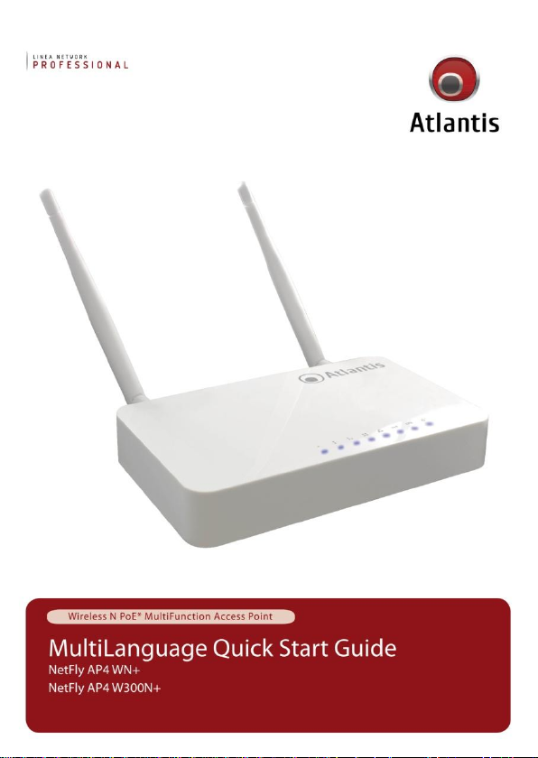
Page 1
Page 2
ITALIANO
Questo prodotto è coperto da garanzia Atlantis della durata di 2 anni. Per maggiori
dettagli in merito o per accedere alla documentazione completa in Italiano fare
riferimento al sito www.atlantis-land.com.
ENGLISH
This product is covered by Atlantis 2 years warranty. For more detailed informations
please refer to the web site www.atlantis-land.com.
For more detailed instructions on configuring and using this device, please refer to
the online manual.
FRANCAIS
Ce produit est couvert par une garantie Atlantis de 2 ans. Pour des informations
plus détaillées, référez-vous svp au site Web www.atlantis-land.com.
DEUTSCH
Dieses Produkt ist durch die Atlantis 2 Jahre Garantie gedeckt. Für weitere
Informationen, beziehen Sie sich bitte auf Web Site www.atlantis-land.com.
ESPAÑOL
Este producto esta cubierto por Atlantis con una garantía de 2 años. Para mayor
información diríjase a nuestro sitio Web www.atlantis-land.com.
2
Page 3

ITALIANO
1. PANORAMICA DI PRODOTTO ............................................................ 10
1.1 Requisiti di sistema .................................................................... 11
1.2 CONTENUTO DELLA CONFEZIONE .............................................. 11
1.3 I LED frontali ............................................................................. 11
1.4 Le porte posteriori ..................................................................... 12
1.5 Cablaggio .................................................................................. 12
1.6 Settaggi di Default ..................................................................... 13
1.7 Configurazione TCP/IP ............................................................... 14
Configurazione del client per Windows XP ......................................... 14
Configurazione del PC in Windows 7 ................................................. 14
Configurazione del PC in Windows Vista ............................................ 14
Configurazione del PC in Windows 2000 ........................................... 15
Configurazione del PC in Windows XP .............................................. 15
Configurazione del PC in MAC OS .................................................... 16
2. Configurazione del NetFly AP4 ........................................................... 16
2.1 Configurazione Tramite WEB ...................................................... 16
2.2 Modalità Operativa ..................................................................... 17
3. Risoluzione dei problemi .................................................................... 19
A.1 Utilizzare i LED per la diagnosi dei problemi ................................. 19
A.1.1 LED Power ..................................................................... 19
A.1.2 LED LAN ......................................................................... 19
A.3 Interfaccia LAN .......................................................................... 19
A.4 Reset ................................................................................. 20
A.5 Interfaccia WLAN ....................................................................... 20
4. SUPPORTO OFFERTO ........................................................................ 21
ENGLISH
1. Product Overview ............................................................................. 26
1.1 System Requirements ................................................................ 27
1.2 Package contents ....................................................................... 27
1.3 Front LEDs ................................................................................ 27
1.4 Rear panel and ports .................................................................. 28
1.5 Cabling ............................................................................... 29
1.6 Factory Default Settings ............................................................. 29
1.7 TCP/IP Configuration.................................................................. 30
Configuring PC (Windows 2000) ...................................................... 30
3
Page 4

Configuring PC (WindowsXP) .......................................................... 31
Configuring PC (Windows Vista) ..................................................... 31
Configuring PC (Windows 7) ........................................................... 31
2. Configuring NetFly AP4 ..................................................................... 32
2.1 Browser configuration ................................................................ 32
2.2 Switching between Operating Modes ........................................... 33
3. Support ............................................................................................ 34
FRANCAIS
1. Introduction Sur Le Produit ............................................................... 38
1.1 Besoin système .......................................................................... 39
1.2 Contenu de la boîte .................................................................... 39
1.3 Face avant ................................................................................ 39
1.4 Face arrière ............................................................................... 40
1.5 Câblage ............................................................................... 40
1.6 Configuration initiale .................................................................. 41
1.7 Configuration du TCP/IP ............................................................. 42
Configuration sous Windows 2000 .................................................. 42
Configuration sous Windows XP...................................................... 42
Configuration sous Windows Vista .................................................. 42
Configuration sous Windows 7 ....................................................... 43
2. Configuration du NetFly AP4 .............................................................. 44
2.1 Configuration avec le Browser .................................................... 44
2.2 Modalité Operative ..................................................................... 45
3. Support ............................................................................................ 46
APPENDIX
APPENDIX A: Technical Features ........................................................... 47
A02-AP4-W(300)N+(v1.0)_GX01 (December 2011)
4
Page 5

AVVERTENZE
Abbiamo fatto di tutto al fine di evitare che nel testo, nelle immagini e nelle tabelle
presenti in questo manuale, nel software e nell'hardware fossero presenti degli
errori. Tuttavia, non possiamo garantire che non siano presenti errori e/o omissioni.
Infine, non possiamo essere ritenuti responsabili per qualsiasi perdita, danno o
incomprensione compiuti direttamente o indirettamente, come risulta dall'utilizzo del
manuale, software e/o hardware.
Il contenuto di questo manuale è fornito esclusivamente per uso informale, è
soggetto a cambiamenti senza preavviso (a tal fine si invita a consultare il sito
www.atlantisland.it o www.atlantis-land.com per reperirne gli aggiornamenti) e non
deve essere interpretato come un impegno da parte di Atlantis che non si assume
responsabilità per qualsiasi errore o inesattezza che possa apparire in questo
manuale. Nessuna parte di questa pubblicazione può essere riprodotta o trasmessa
in altra forma o con qualsiasi mezzo, elettronicamente o meccanicamente, comprese
fotocopie, riproduzioni, o registrazioni in un sistema di salvataggio, oppure tradotti
in altra lingua e in altra forma senza un espresso permesso scritto da parte di
Atlantis. Tutti i nomi di produttori e dei prodotti e qualsiasi marchio, registrato o
meno, menzionati in questo manuale sono usati al solo scopo identificativo e
rimangono proprietà esclusiva dei loro rispettivi proprietari.
Restrizioni di responsabilità CE/EMC
Il prodotto descritto in questa guida è stato progettato, prodotto e approvato in
conformità alle regole EMC ed è stato certificato per non avere limitazioni EMC.
Se il prodotto fosse utilizzato con un PC/apparati non certificati, il produttore non
garantisce il rispetto dei limiti EMC. Il prodotto descritto è stato costruito, prodotto e
certificato in modo che i valori misurati rientrino nelle limitazioni EMC. In pratica, ed
in particolari circostanze, potrebbe essere possibile che detti limiti possano essere
superati se utilizzato con apparecchiature non prodotte nel rispetto della
certificazione EMC. Può anche essere possibile, in alcuni casi, che i picchi di valore
siano al di fuori delle tolleranze. In questo caso l’utilizzatore è responsabile della
“compliance” con i limiti EMC. Il Produttore non è da ritenersi responsabile nel caso
il prodotto sia utilizzato al di fuori delle limitazioni EMC.
CE Mark Warning
In un ambiente domestico il dispositivo può causare interferenze radio, in questo
caso è opportuno prendere le adeguate contromisure.
Dichiarazione di Conformità
Questo dispositivo è stato testato ed è risultato conforme alla direttiva 1999/5/CE
del parlamento Europeo e della Commissione Europea, a proposito di
apparecchiature radio e periferiche per telecomunicazioni e loro mutuo
5
Page 6
Luogo
Banda di Frequenze(MHz)
Potenza (EIRP)
Chiuso (senza
restrizioni)
2400-2483,5
100mW(20dBm)
Aperto
2400-2454
2454-2483,5
100mW(20dBm)
10mW(10dBm)
riconoscimento. Dopo l’installazione, la periferica è stata trovata conforme ai
seguenti standard: EN 300.328(radio), EN 301 489-1, EN 301 489-17(compatibilità
elettromagnetica) ed EN 60950(sicurezza). Questa apparecchiatura può pertanto
essere utilizzata in tutti i paesi della Comunità Economica Europea ed in tutti i paesi
dove viene applicata la Direttiva 1999/5/CE, senza restrizioni eccezion fatta per:
Francia(FR):
(potenza e frequenza) in base alla tabella allegata. Per informazioni ulteriori
consultare
Se l’uso di questa apparecchiatura in ambienti domestichi genera interferenze, è
obbligo dell’utente porre rimedio a tale situazione.
Italia(IT):
i requisiti sull’Assegnazione delle Frequenze. L’utilizzo di questa apparecchiatura al
di fuori di ambienti in cui opera il proprietario, richiede un’autorizzazione generale.
Per ulteriori informazioni si prega di consultare:
Lussemburgo:
l’autorizzazione.
Norvegia (NO):
di raggio nei pressi di Ny Alesund.
Russia (CCP):
Se si utilizza all’aperto tale dispositivo, la potenza in uscita è limitata
www.art-telecom.fr.
Questa periferica è conforme con l’Interfaccia Radio Nazionale e rispetta
www.comunicazioni.it.
Se utilizzato per servizi network o privati è da richiedere
apparecchiatura da non utilizzare in un aresa geografica di 20 km
solo per uso interno.
Dichiarazione di Conformità Sintetica
Con la presente dichiariamo che questo apparato è conforme ai requisiti essenziali
ed alle altre disposizioni pertinenti stabilite dalla direttive 1999/5/CE. La
dichiarazione di conformità nella sua forma completa è disponibile presso il sito
www.atlantis-land.com (alla pagina del prodotto) o può essere richiesta a
info@atlantis-land.com.
6
Page 7

riciclaggio/smaltimento di questa apparecchiatura
Importanti informazioni per il corretto
Il simbolo qui sotto indicato, riportato sull'apparecchiatura elettronica da Lei
acquistata e/o sulla sua confezione, indica che questa apparecchiatura elettronica
non potrà essere smaltita come un rifiuto qualunque ma dovrà essere oggetto di
raccolta separata.
Infatti i rifiuti di apparecchiatura elettroniche ed elettroniche devono essere
sottoposti ad uno specifico trattamento, indispensabile per evitare la dispersione
degli inquinanti contenuti all''interno delle apparecchiature stesse, a tutela
dell'ambiente e della salute umana. Inoltre sarà possibile riutilizzare/riciclare parte
dei materiali di cui i rifiuti di apparecchiature elettriche ed elettroniche sono
composti, riducendo così l'utilizzo di risorse naturali nonché la quantità di rifiuti da
smaltire.
Atlantis, in qualità di produttore di questa apparecchiatura, è impegnato nel
finanziamento e nella gestione di attività di trattamento e recupero dei rifiuti di
apparecchiature elettriche ed elettroniche compatibili con l'ambiente e con la salute
umana.
E' Sua responsabilità, come utilizzatore di questa apparecchiatura elettronica,
provvedere al conferimento della stessa al centro di raccolta di rifiuti di
apparecchiature elettriche ed elettroniche predisposto dal Suo Comune. Per
maggiori informazioni sul centro di raccolta a Lei più vicino, La invitiamo a
contattare i competenti uffici del Suo Comune.
Qualora invece avesse deciso di acquistare una nuova apparecchiata elettronica di
tipo equivalente e destinata a svolgere le stesse funzioni di quella da smaltire, potrà
portare la vecchia apparecchiatura al distributore presso cui acquista la nuova. Il
distributore sarà tenuto ritirare gratuitamente la vecchia apparecchiatura1.
Si tenga presente che l'abbandono ed il deposito incontrollato di rifiuti sono puniti
con sanzione amministrativa pecuniaria da € 103 a € 619, salvo che il fatto
costituisca più grave reato. Se l'abbandono riguarda rifiuti non pericolosi od
ingombranti si applica la sanzione amministrativa pecuniaria da € 25 a € 154.
Il suo contributo nella raccolta differenziata dei rifiuti di apparecchiature elettriche
ed elettroniche è essenziale per il raggiungimento di tutela della salute umana
connessi al corretto smaltimento e recupero delle apparecchiature stesse.
7
Page 8
Tutte le condizioni di utilizzo, avvertenze e clausole
contenute in questo manuale e nella garanzia si intendono
note ed accettate. Si prega di restituire immediatamente
(entro 7 giorni dall’acquisto) il prodotto qualora queste non
siano accettate.
1 Il distributore non sarà tenuto a ritirare l'apparecchiatura elettronica qualora vi sia un rischio di
contaminazione del personale incaricati o qualora risulti evidente che l'apparecchiatura in
questione non contiene i suoi componenti essenziali o contiene rifiuti diversi da apparecchiature
elettriche e/o elettroniche.
NB: le informazioni sopra riportate sono redatte in conformità alla Direttiva 2002/96/CE ed al D.
nonché particolari modalità di trattamento e smaltimento dei rifiuti di apparecchiature elettriche ed
elettroniche (RAEE). Per ulteriori informazioni in materia, la invitiamo a consultare il nostro sito
www.atlantis-land.com
AVVERTENZE
Utilizzare esclusivamente l’antenna fornita a corredo. Antenne diverse e/o con
guadagno differente potrebbero violare le normative vigenti. Atlantis si intende
sollevata da ogni responsabilità in caso di utilizzo di accessori (antenne e/o
alimentatori) non contenuti nell’imballo.
Lasciare almeno 30cm di distanza tra l’antenna del dispositivo e l’utilizzatore.
Non usare il dispositivo in un luogo in cui ci siano condizioni di alte
temperatura ed umidità, il dispositivo potrebbe funzionare in maniera
impropria e danneggiarsi.
Non usare la stessa presa di corrente per connettere altri apparecchi al di fuori
del dispositivo in oggetto
Non aprire mai il case del dispositivo né cercare di ripararlo da soli.
Se il dispositivo dovesse essere troppo caldo, spegnerlo immediatamente e
rivolgersi a personale qualificato.
Non appoggiare il dispositivo su superfici plastiche o in legno che potrebbero
non favorire lo smaltimento termico.
Mettere il dispositivo su una superficie piana e stabile
Usare esclusivamente l’alimentatore fornito nella confezione, l’uso di altri
alimentatori farà automaticamente decadere la garanzia.
Non effettuare upgrade del firmare utilizzando apparati/client wireless ma
solo wired. Questo potrebbe danneggiare il dispositivo ed invalidare la
garanzia.
8
Page 9
La marcatura CE con il simbolo di attention Mark (
) poste sull’etichetta di prodotto potrebbero
non rispettare le dimensioni minime stabilite dalla
normativa a causa delle ridotte dimensioni di quest’ultima.
Atlantis invita a visitare il sito web www.atlantis-land.com
alla relativa pagina di prodotto per reperire manualistica e
contenuti tecnici (aggiornamenti driver e/o funzionalità,
utility, support note) aggiornati.
Il logo WEEE ( ) posto sull’etichetta di prodotto
potrebbe non rispettare le dimensioni minime stabilite dalla
normativa a causa delle ridotte dimensioni di quest’ultima.
Si ricorda che tale dispositivo non è adatto a gestire
abbonamenti non FLAT o a consumo. Atlantis non
potrà essere ritenuta responsabile per qualsiasi
problematica derivante dall’utilizzo di abbonamenti a
consumo (non FLAT) o da una errata configurazione
dell’apparato. In caso di dubbio contattare
preventivamente l’assistenza tecnica.
Per usufruire delle condizioni di garanzia
migliorative associate al prodotto (Fast Swap, On
Site e On Center) è opportuno provvedere alla
registrazione dello stesso sul sito www.atlantisland.com entro e non oltre 15 giorni dalla data di
acquisto. La mancata registrazione entro il termine
di sopra farà si che il prodotto sia coperto
esclusivamente dalla condizioni standard di
garanzia.
9
Page 10

La ringraziamo per aver scelto un apparato della famiglia NetFly, la via più semplice
per il Wireless networking. Questo documento è inteso come una guida rapida,
pertanto per ulteriori dettagli sulla configurazione fare riferimento al manuale esteso
contenuto nel CD.
1. PANORAMICA DI PRODOTTO
Standard IEEE 802.11n
NetFly AP4 WN+ (o NetFly AP4 W300N+) è un Access Point multifunzione, con 5
porte LAN, in standard N progettato per soddisfare ogni esigenza sia in ambito
domestico, che nella piccola e media azienda.
Il supporto del recente standard N a 150Mbps (300Mbps) permette di ottenere un
throughput ed una copertura decisamente superiori rispetto ad una rete in standard
g. Il dispositivo garantisce inoltre il pieno supporto hardware, senza nessuna
degradazione di performance, degli standard di sicurezza più recenti, come il Wi-Fi
Protected Access (WPA/WPA2).
La rete wireless sarà finalmente scattante ed a prova di hacker.
Access Point Multi-Funzione
La funzionalità WDS, utilizzando i più evoluti sistemi di sicurezza, permette,
connettendo sino a 4 Access Point, di estendere la copertura wireless anche in zone
remote.
La modalità Repeater, ideale in ambito domestico, permette di rilanciare il segnale
wireless di un altro apparato ampliandone così la copertura.
La modalità Router (opzionale) permette di aggiungere tra le 2 interfacce
(Wireless/Ethernet o LAN/WAN) i servizi NAT e di analisi del traffico quali Firewall e
QoS.
Access point multipli virtuali
Il supporto Multi-SSID e client isolation permettono di creare sino a 3 Access Point
virtuali con permessi di accesso diversificati.
Le dimensione compatte, il supporto al Passive PoE e la possibilità del montaggio a
muro, rendendo il dispositivo di facile collocazione.
10
Page 11
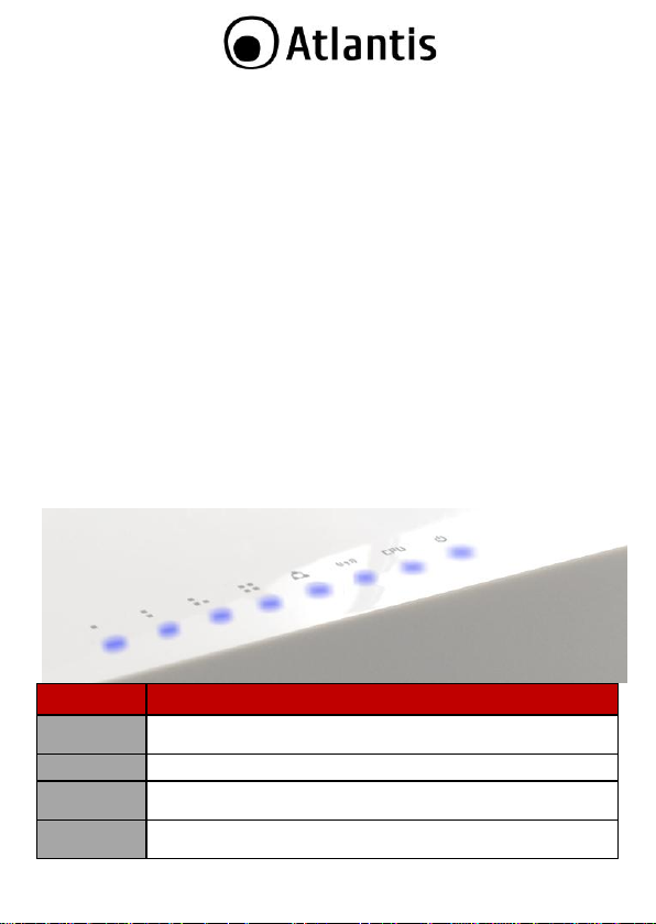
LED
SIGNIFICATO
PWR
Acceso blu durante il corretto funzionamento.
Lampeggiante durante la fase di reset.
CPU
Lampeggiante durante il corretto funzionamento.
WLAN
Accesso blu in caso di connessione attiva.
Lampeggiante in caso di trasmissione/ricezione dati.
WAN
Accesso blu in caso di connessione attiva.
Lampeggiante in caso di trasmissione/ricezione dati.
1.1 Requisiti di sistema
Prima di procedere con l’installazione del prodotto verificare di disporre dei seguenti
requisiti:
Protocollo TCP/IP installato in ogni PC
Un browser WEB quali Internet Explorer 5.0 o superiore, Netscape Navigator
6.0 o superiore
1.2 CONTENUTO DELLA CONFEZIONE
Prima dell’utilizzo, verificare che la scatola contenga i seguenti elementi:
NetFly AP4 WN+ p NetFly AP4 W300N+
Alimentatore AC-DC (5V@1A)
Cavo di rete CAT-5 e un’antenna da 4 dBi (2 antenne per il NetFly AP4W+)
Una guida rapida multilingua (Italiano, Inglese e Francese)
Cd-Rom contenente manualistica multilingua (Italiano, Inglese)
Coupon di Garanzia e WEEE
Nel caso in cui il contenuto non sia quello sovradescritto, contattare il
proprio rivenditore immediatamente.
1.3 I LED frontali
11
Page 12
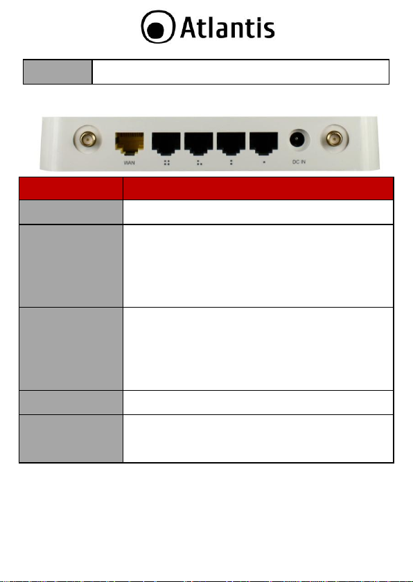
LAN (1-4)
Acceso blu in caso di collegamento a 100 Mbps.
Lampeggiante in caso di trasmissione/ricezione dati.
PORTA
SIGNIFICATO
R-SMA
Avvitare delicatamente l’antenna (o le antenne nel
modello NetFly AP4W300N+) fornita a corredo.
DC-IN
Connettere l’alimentatore a questo jack. L’alimentatore ha
i seguenti valori di targa: AC-DC (5V@1A). Connettere
prima l’alimentatore alla rete elettrica e dopo qualche
secondo al dispositivo.
Il dispositivo, tramite il codice A02-Adapter3, può
essere alimentato in modalità Passive PoE (utilizzare le
porte WAN o LAN1).
WAN
Connettere con un cavo UTP. Il dispositivo di default ha 5
porte configurate tutte come LAN (Operation
Mode=Bridge).
Nel caso in cui funzioni in modalità Gateway questa porta
è configurata come WAN.
Nel caso in cui funzioni in modalità Wireless ISP questa
porta è configurata come LAN.
RJ45(LAN)
Connettere con un cavo UTP. Il dispositivo di default ha 5
porte configurate tutte come LAN.
RESET (Parte
inferiore)
Dopo che il dispositivo è acceso, premere per 6 secondi o
più: (sino a che tutti i LED LAN inizino a lampeggiare) per
effettuare un ritorno alle condizioni di default (utilizzare,
per esempio, in caso si perdesse la password).
1.4 Le porte posteriori
1.5 Cablaggio
Anzitutto collegare una qualsiasi delle porte RJ45 alla Lan e collegare l’alimentatore
alla presa elettrica, poi dopo qualche secondo all’Access Point. Una volta effettuati
tutti i collegamenti il prodotto effettuerà una diagnostica la cui durata è di circa 2
minuti. Terminata questa fase il Led POWER sarà acceso blu fisso, il LED CUP
12
Page 13
lampeggiante ed il i Led LAN/WLAN saranno accesi (a seconda dei collegamenti
fatti) o lampeggianti.
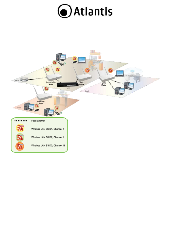
In figura un esempio di installazione tipica in cui l’apparato viene utilizzato
mostrando tutta la sua duttilità (come AP, in Multi SSID, come repeater ed in
modalità WDS).
1.6 Settaggi di Default
Prima di iniziare la configurazione dell’Atlantis Wireless Multi-Function Access Point è
necessario conoscere quali siano i settaggi di default. Lasciando questi settaggi e
impostando sui PC un idirizzo IP statico privato (come da istruzioni seguenti) è
possibile utilizzare l’Atlantis Wireless Multi-Function Access Point in pochissimo
tempo. L’indirizzo IP, normalmente appartenente ad una classe privata, deve stare
nella classe 192.168.1.x con Subnet 255.255.255.0. Anzitutto è necessario
preparare i PC inserendovi (qualora non vi fosse già) la scheda di rete / Adattatore
Wireless. E’ necessario poi installare il protocollo TCP/IP. Qualora il TCP/IP non
fosse correttamente configurato, seguire gli steps successivi. Per una
13
Page 14
Il Supporto al Passive PoE prevede l'utilizzo del
codice A02-Adapter03.
configurazione più dettagliata fare riferimento al manuale presente sul CD. Le
configurazioni di Default dell’Atlantis Wireless Multi-Function Access Point sono:
Username:admin
Password: atlantis
Indirizzo IP LAN: (192.168.1.252), Subnet Mask (255.255.255.0)
DHCP Server: abilitato (192.168.1.50 - 192.168.1.99)
Wireless SSID: A02-AP4-W300N+ or A02-AP4-WN+
Canale: Automatico
Wireless Security: WPA2-PSK (AES/CCMP), Password: NetFlyAP4
Modalità di funzionamento: Bridge (Access Point con 5 porte LAN)
1.7 Configurazione TCP/IP
Configurazione del client per Windows XP
Configurazione del PC in Windows 7 Andare su Start poi Pannello di Controllo (cliccare sulla voce Icone
Piccole o Grandi) e qui cliccare due volte sull’icona Centro Connessione
di rete e Condivisione, poi cliccare su Modifica Impostazione Scheda.
Cliccare 2 volte sull’icona Local Area Connection/Wireless e cliccare su
Proprietà poi cliccare su Continua (per continuare è necessaria
l’utorizzazione dell’utente).
Selezionare Protocollo Internet Versione 4 Protocol (TCP/IPv4) e
cliccare su Proprietà.
Selezionare l’opzione Ottieni automaticamente un indirizzo IP e
successivamente Ottieni indirizzi server DNS automaticamente.
Premere su OK per terminare la configurazione.
Configurazione del PC in Windows Vista Andare su Start poi Pannello di Controllo (cliccare sulla voce
Visualizzazione classica) e qui cliccare due volte sull’icona Centro
Connessione di rete e Condivisione, poi cliccare su Gestisci
connessione di rete.
14
Page 15

Cliccare 2 volte sull’icona Local Area Connection/Wireless e cliccare su
Proprietà poi cliccare su Continua (per continuare è necessaria
l’utorizzazione dell’utente).
Selezionare Protocollo Internet Versione 4 Protocol (TCP/IPv4) e
cliccare su Proprietà.
Selezionare l’opzione Ottieni automaticamente un indirizzo IP e
successivamente Ottieni indirizzi server DNS automaticamente.
Premere su OK per terminare la configurazione.
Configurazione del PC in Windows 2000 Andare su Start/Settings/Control Panel. Cliccare due volte su Network
and Dial-up Connections.
Cliccare due volte su Local Area Connection.
In Local Area Connection Status/Wireless cliccare Properties.
Selezionare Internet Protocol (TCP/IP) e cliccare su Properties.
Selezionare l’opzione Obtain an IP address automatically e
successivamente Obtain DNS server address automatically.
Premere su OK per terminare la configurazione.
Configurazione del PC in Windows XP Andare su Start e poi Panello di Controllo. Cliccare due volte su
Connessione di rete (se non fosse presente cliccare prima su: Passa alla
Visualizzazione Classica).
Cliccare due volte su Connessione alla rete locale (LAN)/Wireless.
Nel TAB generale cliccare Proprietà.
Selezionare Protocollo Internet (TCP/IP) e cliccare su Proprietà.
Selezionare l’opzione Ottieni automaticamente un indirizzo IP e
successivamente Ottieni indirizzi server DNS automaticamente.
Premere su OK per terminare la configurazione.
15
Page 16

Configurazione del PC in MAC OS
Cliccare sull’icona Mela nell’angolo in alto a sinistra dello schermo e
selezionare: Control Panel/TCP/IP. Apparirà la finestra relativa al TCP/IP
come mostrata in figura.
Scegliere Ethernet in Connect Via.
Scegliere Using DHCP Server in Configure.
Lasciare vuoto il campo DHCP Client ID.
2. Configurazione del NetFly AP4
2.1 Configurazione Tramite WEB
Accedere col browser web al seguente indirizzo IP che di default è:
192.168.1.252. Premere il tasto invio.
Utilizzare admin (come nome utente) e atlantis (come password). Premere OK
per continuare.
Apparirà a questo punto il Menù Principale, nella cui parte superiore è possibile
leggere la modalità in cui sta funzionando il NetFly AP4. I menù disponibili sono:
NetFly AP4 Series
System
Wireless
TCP/IP
Firewall
Management
Cliccando sulla sezione desiderata, nello spazio della homepage appariranno tutti i
settaggi relativi alla configurazione della sezione scelta, oppure si apriranno tutta
una serie di sottosezioni tra cui scegliere prima di avere accesso alle configurazione
vere e proprie.
16
Page 17

2.2 Modalità Operativa
L’access Point parte di default in modalità Bridge.
Cliccare in NetFly AP4 Series->Operation Mode per cambiare la modalità
operativa:
Gateway: In questa modalità il NetFly diventa un vero e proprio router la cui
WAN è la connessione Ethernet (configurata di default in client DHCP) il cui
indirizzo IP è condiviso sulle 4 porte LAN e la WLAN (il NAT è attivo).
L’indirizzo IP di default è 192.168.1.252 con DHCP attivo
sull’interfaccia LAN/Wireless (è possibile accedere dalle sole interfacce
LAN/WLAN).
Bridge (configurazione di default): E’ possible utilizzare il NetFly come un
vero e proprio Access Point con 5 porte LAN. L’indirizzo IP di default è
192.168.1.252 (è possibile accedere tanto dall’interfaccia ETH che WLAN).
Il server DHCP è abilitato.
Wireless ISP: E’ possible utilizzare il NetFly come un Router la cui WAN è la
sezione Wireless che va collegata ad un apposito Access Point. Alle 5 porte,
tutte configurate come LAN, del dispositivo possono essere collegati diversi
apparecchi (la WLAN, tramite NAT, è condivisa da tutti i dispositivi collegati a
queste 5 porte fisiche). L’indirizzo IP di default è 192.168.1.252 con
17
Page 18

Modalità
Indirizzo IP
Accesso
DHCP
Access Point (Bridge)
192.168.1.252
ETH (5 ports)
WLAN
Abilitato
(192.168.1.50-
192.168.1.99)
Gateway
192.168.1.252
ETH (4 ports)
WLAN
Abilitato
(192.168.1.50-
192.168.1.99)
Wireless ISP
192.168.1.252
ETH (5 ports)
Abilitato
(192.168.1.50-
192.168.1.99)
DHCP attivo sull’interfaccia LAN (è possibile accedere dalla sola
interfaccia ETH).
In figura un riassunto delle varie modalità disponibili, Indirizzo IP utilizzato e le
interfacce da cui è possibile avere accesso alla configurazione web del NetFly.
Per maggiori dettagli si faccia riferimento al manuale completo presente su CD.
18
Page 19

Steps
Azione Correttiva
1
Accertarsi che l’alimentatore sia connesso al NetFly AP4 e alla rete
elettrica. Utilizzare unicamente l’alimentatore fornito a corredo
(5V@1A, AC-DC).
2
Verificare che l’alimentatore sia connesso a una presa elettrica attiva
e in grado di fornire la tensione necessaria al funzionamento del
prodotto.
3
Accertarsi che il Plug dell’alimentatore sia correttamente inserito.
4
Se il problema persiste contattare l’assistenza tecnica Atlantis.
Steps
Azione Correttiva
1
Verificare la connessione del cavo di rete tra l’Access Point e il PC o
lo Switch di rete.
2
Verificare che il cavo sia funzionante.
3
Verificare che la scheda di rete del PC funzioni correttamente.
4
Se il problema persiste contattare l’assistenza tecnica Atlantis.
Steps
Azione correttiva
1
Accertarsi di utilizzare Internet Explorer 5 o una versione successiva.
2
Eliminare i files temporanei di Internet ed eseguire un nuovo login.
Steps
Azione correttiva
3. Risoluzione dei problemi
Questo capitolo illustra come identificare e risolvere eventuali problemi sul NetFly.
A.1 Utilizzare i LED per la diagnosi dei problemi
I LEDs sono un utile strumento per individuare eventuali problemi, osservandone lo
stato è possibile individuare velocemente dove si verifica un eventuale
malfunzionamento.
A.1.1 LED Power
Il LED PWR non si accende
A.1.2 LED LAN
Il LED LAN non si accende.
A.3 Interfaccia LAN
Le schermate di configurazione Web non vengono visualizzate
correttamente.
Non è possible accedere al NetFly dalla LAN e nemmeno eseguire un ping
dal router verso i PC della rete.
19
Page 20

1
Verificare che il LED relativo alla porta LAN posti sul pannello
frontale del NetFly sia acceso. Se il LED è spento fare riferimento
alla sezione A.1.2.
2
Accertarsi di utilizzare un indirizzo IP corretto sul PC. Questo deve
avere un indirizzo IP impostato manualmente (se come client DHCP
non riesce ad ottenere l'IP) del tipo 192.168.1.5, Subnet
255.255.255.0.
Collegare il PC direttamente al NetFly.
3
Se è stato modificato l’indirizzo IP del NetFly è necessario modificare
L’URL di accesso al prodotto.
4
Se i problemi persistono effettuare un reset dell’apparato.
Steps
Azione correttiva
1
Premere, a dispositivo funzionante, il tasto di reset e tenerlo
premuto (per circa 6 secondi) sino a che il LED LAN non si
accendono tutti.
Il dispositivo si riporterà nelle condizioni iniziali.
Username:admin
Password: atlantis
Indirizzo IP LAN: (192.168.1.252), Subnet Mask
(255.255.255.0)
DHCP Server: abilitato
Modalità di funzionamento: Bridge
2
Se il problema persistesse, collegare il dispostivo alla rete elettrica
ed attendere che il boot sia terminato. Ripetere il punto 1.
3
Se il problema persiste contattare l’assistenza tecnica Atlantis.
Steps
Azione correttiva
1
Accertata l’avvenuta connessione con la WLAN del NetFly , provare
ad aggiornare i driver del client wireless.
2
Verificare che ci sia un server DHCP nella rete o che tale serve sia
abilitato nel NetFly (nelle modalità di funzionamento che lo
permettono).
3
Talune volte infatti il pacchetto DHCP non riesce a passare a cause
A.4 Reset
Come posso effettuare il reset del dispositivo?
A.5 Interfaccia WLAN
Il client wireless, configurato in DHCP, non riceve l’indirizzo IP tramite il
NetFly AP4.
20
Page 21

di settaggi RTS Threshold e Fragmentation Threshold(bytes).
Nella sezione Wireless->Advanced abbassare tali valori.
Riprovare verificando se l’attribuzione dell’indirizzo IP avvenga
correttamente. Alternativamente tale parametro andrebbe impostato
anche sui driver del client wireless.
Se il problema persistesse, procedere come da punto 4.
3
Assegnare al client Wireless un indirizzo IP statico (del tipo
192.168.1.5, subnet=255.255.255.0) e provare ad effettuare un
ping verso l’indirizzo IP del NetFly.
4. SUPPORTO OFFERTO
Per qualunque altro problema o dubbio sul funzionamento del prodotto, è possibile
contattare il servizio di assistenza tecnica Atlantis tramite l’apertura di un ticket on-
line sul portale http://www.atlantis-land.com/ita/supporto.php.
Nel caso non fosse possibile l’accesso al portale di supporto, è altresì possibile
richiedere assistenza telefonica al numero 02/ 78.62.64.37 (consultare il sito per
verificare gli orari in cui il servizio viene erogato).
Per esporre eventuali richieste di supporto prevendita o richieste di contatto , si
invita ad utilizzare gli indirizzi mail info@atlantis-land.com oppure
prevendite@atlantis-land.com.
Atlantis SpA
Via S. Antonio, 8/10
20020 Lainate (MI)
Fax: +39.02.78.62.64.39
Website: http://www.atlantis-land.com
Email: info@atlantis-land.com
21
Page 22

Copyright Statement
No part of this publication may be reproduced, stored in a retrieval system, or
transmitted in any form or by any means, whether electronic, mechanical,
photocopying, recording or otherwise without the prior writing of the publisher.
Windows™ 98SE/2000/ME/XP/VISTA are trademarks of Microsoft® Corp. Pentium is
trademark of Intel. All copyright reserved.
The Atlantis logo is a registered trademark of Atlantis. All other names mentioned
mat be trademarks or registered trademarks of their respective owners. Subject to
change without notice. No liability for technical errors and/or omissions.
Wireless LAN, Health and Authorization for use
Radio frequency electromagnetic energy is emitted from Wireless LAN devices. The
energy levels of these emissions however are far much less than the
electromagnetic energy emissions from wireless devices like for example mobile
phones. Wireless LAN devices are safe for use frequency safety standards and
recommendations. The use of Wireless LAN devices may be restricted in some
situations or environments for example:
On board of airplanes, or
In an explosive environment, or
In case the interference risk to other devices or services is perceived or
In case the policy regarding the use of Wireless LAN devices in specific
organizations or environments (e.g. airports, hospitals, chemical/oil/gas industrial
plants, private buildings etc.) is not clear, please ask for authorization to use these
devices prior to operating the equipment.
Regulatory Information/disclaimers
Installation and use of this Wireless LAN device must be in strict accordance with
the instructions included in the user documentation provided with the product. Any
changes or modifications made to this device that are not expressly approved by the
manufacturer may void the user’s authority to operate the equipment. The
Manufacturer is not responsible for any radio or television interference caused by
unauthorized modification of this device, of the substitution or attachment.
Manufacturer and its authorized resellers or distributors will assume no liability for
any damage or violation of government regulations arising from failing to comply
with these guidelines.
CE Mark Warning
In a domestic environment, this product may cause radio interference, in which case
the user may be required to take adequate measures.
identified as harmful
22
Page 23

Location
Frequency Band (MHz)
Power (EIRP)
Indoor (no restriction)
2400-2483,5
100mW(20dBm)
Outdoor
2400-2454
2454-2483,5
100mW(20dBm)
10mW(10dBm)
CE in which Countries where the product may be used freely:
Germany, UK, Italy, Spain, Belgium, Netherlands, Portugal, Greece, Ireland,
Denmark, Luxembourg, Austria, Finland, Sweden, Norway and Iceland.
France: except the channel 10 through 13, law prohibits the use of other channels.
CE/EMC Restriction of Liability
The product described in this handbook was designed, produced and approved
according to the EMC-regulations and is certified to be within EMC limitations.
If the product is used in an uncertified PC, the manufacturer undertakes no
warranty in respect to the EMC limits. The described product in this handbook was
constructed, produced and certified so that the measured values are within EMC
limitations. In practice and under special circumstances, it may be possible, that
the product may be outside of the given limits if it is used in a PC that is not
produced under EMC certification. It is also possible in certain cases and under
special circumstances, which the given EMC peak values will become out of
tolerance. In these cases, the user himself is responsible for compliance with the
EMC limits.
Declaration of Conformity
This equipment has been tested and found to comply with Directive 1999/5/CE of
the European Parliament and of the Council on radio equipment and
telecommunications terminal equipment and the mutual recognition of their
conformity. After assessment, the equipment has been found to comply with the
following standards: EN 300.328 (radio), EN 301 489-1, EN 301 489-17
(electromagnetic compatibility) and EN 60950 (safety). This equipment may be used
in all European Union contries and in all countries applying Directive 1999/5/CE,
without restriction, with the exception of the following countries:
France (FR):
within the frequency bans listed on the chart. For more info, consult the website
www.art-telecom.fr.
When this equipment is used outdoors, output power is limited to
Italy(IT):
Luxembourg:
For more info, consult the website
General authorization requie for network and service supply.
www.comunicazioni.it
23
Page 24

Norway (NO):
of 20 km from the center of Ny Alesund.
Russia (CCP):
Declaration of Conformity
Hereby We declare that this product is in compliance with the essential
requirements and other relevant provisions of Directive “Electromagnetic
Compatibility” and 1999/5/CE within CE Marking Requirememnt.
CE Declaration is available on the web site www.atlantis-land.com.
procedures of this equipment
The crossed-out wheeled bin symbol printed on the unit label or unit packaging
indicates that this equipment must not be disposed of as unsorted municipal waste
but it should be collected separately.
The waste of electric and electronic equipment must be treated separately, in order
to ensure that hazardous materials contained inside the equipment are not buried
thereby providing potential future problems for the environment and human health.
Moreover, it will be possible to reuse and recycle some parts of the waste of electric
and electronic equipment, contributing to reduce the quantities of waste to be
disposed of and the depletion of natural resources.
As user of this equipment, you are responsible to return this waste of electronic
equipment to an authorised collection facility set up by your Municipality. More
detailed information on your nearest collection centre can be obtained from your
Municipality or from other competent local entities.
If you are replacing the old equipment with a new equivalent product, the
distributor must take-back the old equipment free of charge on a one-to one basis
as long as the equipment is of equivalent type and fulfilled the same functions as
the supplied equipment.
Your rôle in participating to the separate collection of waste of electric and
electronic equipment is essential to ensure that environmental protection and
This subsection does not apply for geographical area within a radius
only for indoor application.
Important information for the correct recycle/treatment
24
Page 25

CE Logo with attention Mark ( ) aren’t fully
compliant with minimum dimensions requirement to
European Directive due to limited sticker area.
WEEE BIN Logo ( ) isn’t fully compliant with
minimum dimensions requirement to European Directive
due to limited sticker area.
Atlantis suggest to vistit the web site www.atlantis-
land.com in order to retrieve update manual, techsheet
and driver.
Before starting, take a few minutes to read this manual.
Read all of instructions and save this manual for later
reference.
human health objectives connected to a responsible treatment and recycling
activities are achieved.
PS.: The above mentioned information are reported herewith in compliance with Directive
2002/96/CE, which requires a separate collection system and specific treatment and disposal
procedures for the waste of electric and electronic equipments (WEEE). For further and more
detailed information, we invite you to visit our website at www.atlantis-land.com
25
Page 26

Thank You for choosing an Atlantis Product. For more detailed instructions on
configuring and using the NetFly AP4, please refer to the online manual into CD.
1. Product Overview
IEEE 802.11n Wireless
Thanks to its embedded Access Point, based on the most recently 802.11n (up to
150/300Mbps) specifications, is possible to create high performance WLANs with
extended coverage. NetFly is designed to operate in every working environment
(domestic or SoHo).
No more dead zones and high speed (up to 6 times than traditional IEEE802.11b/g
networks) are the most impressive characteristics of this innovative wireless
technology, that ensure excellent throughtput performances merging with total
freedom of mobility.
The chipsets fully support Wi-Fi Protected Access (WPA/WPA2) security standards in
hardware and high-speed encryption engines with no performance degradation.
Multi-Function Access Point
The WDS (up to 4 AP) feature makes the device an ideal solution for quickly
creating and extending a wireless local area network (WLAN) in offices or other
workplaces. Repeater Mode is able to extend the effective range and coverage of
the wireless network.
When Router function is enabled, it is possible to add between the 2 interfaces
(Wireless/Ethernet or LAN/WAN) different services (NAT, firewall and QoS).
Virtual AP
The device supports up to 3 SSIDs with client isolation that allows NetFly to
perform as multiple virtual access points.
Wall Plug mount, Passive PoE and compact size for an easy installation.
26
Page 27

LED
MEANING
PWR
Lit Blue when power is plugged in and the system is
ready.
CPU
Blinking when firware is ok.
WLAN
Flashes when sending/receiving data. Lit blue when the
wireless connection is established.
1.1 System Requirements
Before installing Router, your PC should meet the following:
TCP/IP protocol must be installed on each PC
Web browser, such as Microsoft Internet Explorer 5.0 or later, Netscape
Navigator 6.0 or later
1.2 Package contents
Unpack the package and check all the items carefully. Also, keep the box and
packing materials in case you need to ship the unit in the future. The pack age
should contain the following items:
NetFly AP4 WN+ or NetFly AP4 W300N+
Power Adapter AC-DC (5V, 1A)
UTP cat. 5 cable (RJ-45 connector), 4 dBi Antenna (or 2 x 4 dBi Antennas)
Quick Start Guide (English, Italian and French)
Cd-Rom contained manual
Warranty Card & WEEE Disclaimer
If any item contained is damaged or missing, please contact your local
dealer as soon as possible.
1.3 Front LEDs
27
Page 28

WAN
Lit when connected to Ethernet device (Blue for
10/100Mbps)
Blinking when data transmit/received.
LAN (1-4)
Lit when connected to Ethernet device (Blue for
10/100Mbps)
Blinking when data transmit/received.
PORT
MEANING
DC-IN
Connect the supplied power adapter to this jack.
RJ45(LAN)
Connect an UTP Ethernet cable to one of the four LAN
ports when connecting to a PC or an office/home network
of 10Mbps or 100Mbps.
Reset
After the device has turned on, press it to reset (10
seconds or above) the device will be restored to factory
default settings (this is used when you can not login to
the router, e.g. forgot the password)
R-SMA
Connect the supplied Antenna here.
1.4 Rear panel and ports
28
Page 29

1.5 Cabling
First you must connect the product to the RJ45 ports the PCs of your Lan or others
Switch. In the end connect the DC Adapter to the socket then to the NetFly AP4.
Once you’ve done all the connections the product will carry on immediately a
autotest (120 seconds). With the power source on, once the device is connected,
the Power, LAN and WLAN port LEDs will light up indicating a normal status.
If the LAN Port’s Link indicator does not light up then check the RJ-45 cable if it is
firmly feed to the RJ45 port, while the LAN is link up to the Switch/Hub, the LAN
port’s LED will light up.
The control LEDs of the device are clearly visible and the status of the network link
can be seen instantly.
1.6 Factory Default Settings
The Wireless Multi-Function Access Point can be configured with your Web browser.
The product provides a very easy and user-friendly interface for configuration.
29
Page 30

This section describes the configuration required by LAN-attached PCs that
communicate with the Wireless Multi-Function Access Point, either to configure the
device or for network access. These PCs must have an Ethernet interface (or
wireless adapter) installed properly, be connected to the Wireless Multi-Function
Access Point either directly or through an external repeater hub or by wireless, and
have TCP/IP installed and configured with a fixed IP address that must be in the
same subnet of the Wireless Multi-Function Access Point. The default IP address of
the Wireless Multi-Function Access Point is 192.168.1.252 and subnet mask is
255.255.255.0.
First of all, please check your PC’s network components. The TCP/IP protocol stack
and Ethernet network adapter must be installed. If not, please refer to MS Windows
related manuals.
Following next steps you can make operating NetFly in short time using PCs in
DHCP mode.
Before you configure this Wireless Multi-Function Access Point, you need to know
the following default settings:
Username:admin
Password: atlantis
IP LAN address: (192.168.1.252), Subnet Mask (255.255.255.0)
DHCP Server: Enable (192.168.1.50 - 192.168.1.99)
Wireless SSID: A02-AP4-W300N+ or A02-AP4-WN+
Channel: Automatico
Wireless Security: WPA2-PSK (AES/CCMP), Password: NetFlyAP4
Mode: Bridge (Access Point with 5 F/E Lan Ports)
1.7 TCP/IP Configuration
Configuring PC (Windows 2000) Go to Start / Settings / Control Panel. In the Control Panel, double-click on
Network and Dial-up Connections.
Double-click LAN Area Connection/Wireless.
In the LAN Area Connection/Wireless Status window, click Properties.
Select Internet Protocol (TCP/IP) and click Properties.
Select the Obtain an IP address automatically and the Obtain DNS
server address automatically radio buttons.
Click OK to finish the configuration.
30
Page 31

Configuring PC (WindowsXP)
Go to Start / Control Panel (in Classic View). In the Control Panel, double-
click on Network Connections.
Double-click Local Area Connection/Wireless.
In the LAN Area Connection/Wireless Status window, click Properties.
Select Internet Protocol (TCP/IP) and click Properties.
Select the Obtain an IP address automatically and the Obtain DNS
server address automatically radio buttons.
Click OK to finish the configuration.
Configuring PC (Windows Vista)
Go to Start / Control Panel (in Classic View). In the Control Panel, double-
click on Network and Sharing Center icon.
Click Manage Network connections then double-click Local Area
Connection/Wireless and click Properties.
Click Continue (Windows needs your permission to continue).
Select Internet Protocol Version 4 (TCP/IP) and click Properties.
Select the Obtain an IP address automatically and the Obtain DNS
server address automatically radio buttons.
Click OK to finish the configuration
Configuring PC (Windows 7) Go to Start / Control Panel (select Large/Small Icon). In the Control
Panel, double-click on Network and Sharing Center icon.
Click Change Adapter Settings then double-click Local Area
Connection/Wireless and click Properties.
Click Continue (Windows needs your permission to continue).
Select Internet Protocol Version 4 (TCP/IP) and click Properties.
Select the Obtain an IP address automatically and the Obtain DNS
server address automatically radio buttons.
Click OK to finish the configuration
31
Page 32

2. Configuring NetFly AP4
2.1 Browser configuration
Open the web browser, enter the local port IP address of this NetFly, which default
at 192.168.1.252, and click Go to get the login page.
The default username is admin, password atlantis and click OK to continue. At
the configuration homepage, the left navigation pane where bookmarks are
provided links you directly to the desired setup page, including:
System
Wireless
Network
Management
Tools
Logout
Click on the desired item to expand the page with all settings in the main
navigation panel.
32
Page 33

2.2 Switching between Operating Modes
Click on the System link on the navigation drop-down menu. You will then see five
options: Operation Mode, Status, Schedule, Event Log, and Monitor. Click on
Operation Mode. A dialog box will appear to notify you that the system will
restart in order for the change to take effect. Click on the OK button to continue.
Router Mode (Operation Mode=Gateway): In order to configure NetFly as a
Router, select Access Point with Gateway function from the Operating Mode
drop-down list. IP is 192.168.1.252 ( 4 F/E LAN ports/WLAN). DHCP
Server enable.
Access Point Mode (Operation Mode=Bridge): In order to configure NetFly
as an Access Point, select Bridge from the Operating Mode drop-down list. IP
is 192.168.1.252 (5 F/E LAN ports, WLAN). DHCP Server enable.
Router Mode (Operation Mode=Wireless ISP): In order to configure NetFly
as a Router, select Access Point with Wireles ISP function from the
Operating Mode drop-down list. IP is 192.168.1.252 (5 F/E LAN ports).
DHCP Server enable.
A dialog box will appear to notify you that the system will restart in order for the
change to take effect. Click on the Apply button to continue
For more detailed instructions on configuring and using the NetFly, please refer to
the online manual into CD.
33
Page 34

Operation Mode
IP Address
Accesso
DHCP
Access Point (Bridge)
192.168.1.252
ETH (5 ports)
WLAN
DHCP Server
Enable
(192.168.1.50-
192.168.1.99)
Gateway
192.168.1.252
ETH (4 ports)
WLAN
Wireless ISP
192.168.1.252
ETH (5 ports)
3. Support
For technical questions and support, please contact our help-desk by ticket on
http://www.atlantis-land.com/ita/supporto.php.
For generic informations, please send an e-mail to info@atlantis-land.com.
For presales informations, please send an e-mail to prevendite@atlantis-land.com.
Atlantis SpA
Via S. Antonio, 8/10
20020 Lainate (MI)
Fax: +39.02.78.62.64.39
Website: http://www.atlantis-land.com
Email: info@atlantis-land.com
Copyright
Copyright. 2002 est la propriété de cette société. Tout droits réservés. Sont
interdites, la reproduction, la transmission, la transcription, la mémorisation dans un
système de sauvegarde où la traduction dans une autre langue ou en langage
informatique quels qu’ils soient, de la présente publication, sous quelque forme que
ce soit ou quelque en soit le moyen, électronique, mécanique, magnétique, optique,
34
Page 35

chimique, manuel ou de tout autre genre, sans avoir obtenu préalablement
l’autorisation de notre entreprise.
Non-responsabilité
La présente entreprise n’admet ni requêtes ni de garantie, explicites ou implicites,
au sujet du contenu et de manière spécifique exclue la possibilité de garantie,
communicabilité ou adaptabilité pour des finalités particulières. Le logiciel décrit
dans le présent manuel est vendu ou concédé en licence “tel quel”. Si les
programmes devaient présenter des problèmes après l’achat, l’acquéreur (et non
pas la présente entreprise, son distributeur ou concessionnaire) est tenu de
prendre en charge tous les coûts de manutention ainsi que les coûts dus à des
dommages accidentels ou des conséquences dérivants d’un défaut du logiciel. La
présente entreprise se réserve en outre le droit de revoir le contenu de cette
publication et d’y apporter des modifications de temps en temps, sans obligation
d’informer les utilisateurs de ces changements. Nous avons fait tout notre possible
afin d’éviter la présence d’erreurs dans le texte, les images, les tableaux présents
dans ce manuel et dans le Cd-Rom. Cependant, nous ne pouvons pas garantir
l’absence totale d’erreurs et/ou d’omissions, nous vous remercions donc de nous les
signaler et vous prions de nous en excuser. Enfin, nous ne pouvons être tenus pour
responsables dans quelque perte que ce soit, dommage ou incompréhension à la
suite directe ou indirecte de l’utilisation de notre manuel, le logiciel Cd-Rom et/ou
disque dur.
Toutes les marques ou noms de produits mentionnés dans le présent manuel sont
des marques commerciales et/ou brevetées par leurs propriétaires respectifs.
Marquage CE
Cet appareil peut causer des interférences radio, dans ce cas nous vous invitons à
prendre les contre-mesures appropriées.
ATTENTION
Laisser au moins 30 cm de distance entre les antennes du dispositif et les
utilisateurs.
Domaine de régulation
Chaque pays utilise des bandes de fréquences fixées par cet organisme, l’utilisateur
final doit donc s’assurer du bon réglage de son AP sur un canal autorisé dans son
pays.
Déclaration de Conformité
Cet appareil a été testé et est conforme à la Directive 1999/5/CE du Parlement
européen et du Conseil concernant les équipements hertziens et les équipements de
terminaux de télécommunications et la reconnaissance mutuelle de leur conformité.
Après évaluation du matériel, celui-ci est conforme aux normes suivantes : EN
300.328 (radio), EN 301 489-1, EN 301 489-17(compatibilité électromagnétique),
EN 60950-1 (sécurité) et EN50385. Ce matériel peut être utilisé dasn tous les pays
35
Page 36

Site
Plage de fréquences
(MHz)
Puissance (EIRP)
Intérieur (aucune
restriction)
2400-2483,5
100mW(20dBm)
Extérieur
2400-2454
2454-2483,5
100mW(20dBm)
10mW(10dBm)
de l’Union Européenne et dans tous les pays appliquant la Directive 1999/5/CE, sans
limitations, à l’exception des pays suivants :
France :
En cas d’utilisation de ce matériel en extérieur, la puissance de sortie est limitée
dans les plages de fréquences ci-dessous. Pour de plus amples informations,
consultez le site de l’ART : www.art-telecom.fr
Italie :
Cet appareil est conforme à l’interface radio nationale et aux exigences de la table
d’allocation des fréquences. L’utilisation de ce produit sans fil en dehors du cadre de
la propriété de l’acquéreur nécessite une autorisation générale. Pour da plus amples
informations, consultez le site www.comunicazioni.it
Luxembourg:
Norvège (NO):
Russie (CCP):
Il faut demander une autorisation pour l’installation de cet appareil.
il est interdit d’utiliser cet appareil (20Km) proche de Ny Alesund
Utiliser seulement à l’ Intérieur.
36
Page 37

Déclaration de Conformité
Nous déclarons que cet appareil a été testé et est conforme à la Directive 99/5/CE
du Parlement européen et du Conseil concernant les équipements hertziens et les
équipements de terminaux de télécommunications et la reconnaissance mutuelle de
leur conformité. Il est possible de télécharger sur le site web (www.atlantis-
land.com) le document complet.
équipement
Information importante sur le recyclage et le traitement de cet
Le symbole représentant une poubelle sur roues barrée d'une croix, qui est imprimé
sur l'étiquette ou l'emballage du produit, indique que cet équipement ne doit pas
être éliminé avec les déchets municipaux non triés mais doit faire l'objet d'une
collecte sélective.
Les déchets d'équipements électriques et électroniques doivent être traités
séparément afin d'éviter que les matières dangereuses contenues dans ces
équipements ne soient enterrées, ce qui pourrait occasionner des risques futurs
pour l'environnement et la santé humaine. De plus, certains éléments des déchets
d'équipements électriques et électroniques pourront être réutilisés et recyclés, ce
qui contribuera à réduire les quantités de déchets à éliminer et à limiter
l'épuisement des ressources naturelles.
En tant qu'utilisateur de cet équipement, vous êtes chargé de rapporter ce déchet
d'équipement électronique à un centre de collecte autorisé par votre commune.
Vous pouvez obtenir, auprès de votre commune ou du groupement auquel elle
appartient, de plus amples informations sur votre centre de collecte le plus proche.
Si vous achetez un équipement électrique ou électronique, le distributeur reprendra
gratuitement l'équipement usagé que vous lui cèderez, dans la limite de la quantité
et du type d'équipement vendu.
Votre participation à la collecte sélective des déchets d'équipements électriques et
électroniques est essentielle pour garantir que les objectifs de protection de
l'environnement et de la santé humaine seront atteints.
PS: Les informations susmentionnées sont fournies ici en conformité avec la Directive 2002/96/CE
et le Décret n° 2005-829 du 20 juillet 2005 relatif à la composition des équipements électriques et
électroniques et à l'élimination des déchets issus de ces équipements qui prévoient des
procédures de collecte sélective et de traitement et d'élimination spécifiques aux déchets
d'équipements électriques et électroniques. Pour de plus amples informations, nous vous invitonsà
consulter notre site Internet à l'adresse suivante www.atlantis-land.com.
37
Page 38

Ce guide d’installation rapide vous permet d’installer et de configurer le NetFly AP4
en suivant des paramètres standards. Pour plus de précisions, tant sur les méthodes
de configuration que sur le paramétrage avancé, reportez-vous au manuel sous
format électronique (PDF) disponible sur le CD-Rom fourni.
1. Introduction Sur Le Produit
Mobilité / Wireless
Grâce à sa fonction Wireless, il est possible d'ajouter à son réseau LAN actuel (sans
préoccupation de câbles encombrants et chers) jusqu'à 253 utilisateurs en les
connectant (sans fil) malgré des obstacles tels que murs et cloisons (l'algorithme de
cryptage WPA/WPA2 assure une transmission sécurisée). La technologie Wireless N
(jusqu’à 150/300Mbps) permets d’obtenir une couverture étendue et un débit
constant permanent avec pratiquement aucune zone morte.
Les chipsets supportent le Wi-Fi Protected Access (WPA/WPA2) en hardware, ainsi
que le moteur d'encryptage haute vitesse sans dégradation des performances.
Les fonctions de sécurité avancée vous protègent des attaques de hacker.
Point d’Accès MultiFunction
Le produit peut être configuré pour fonctionner dans n'importe lequel des modes
suivants : Accès sans fil, Répéteur sans fil et enfin Routeur.
La technologie WDS permet aux utilisateurs d'étendre le réseau sans fil en ajoutant
un point d'accès sans fil N supplémentaire (jusqu’à 4 AP).
Le mode Repeat permet d'étendre la portée et la couverture du réseau Wireless.
En choisissant la modalité Routeur, il est possible d'ajouter entre les 2 interfaces
(Wireless/Ethernet ou LAN/WAN) les services NAT et d'analyse du trafic (Pare-Feu
et QoS).
Points d’Accès Virtuel
Le produit supporte jusqu’à 3 SSID et le mécanisme d'isolation de client sans
fils grâce auxquels il agit comme point d’accès virtuel multiple.
La dimension compacte et le Passive PoE permettent un assemblage confortable au
mur, en rendant facile le montage du produit.
38
Page 39

LED
SIGNIFICATION
PWR
Allumé bleu pour indiquer que le système est actif.
CPU
Clignotant combien le produit a terminé de charger le
microcode.
WLAN
Clignotant blue pour indiquer la transmission des donnée.
Allumé pour indiquer le correct fonctionnement de module
1.1 Besoin système
Avant de commencer l’installation vérifiez si vous disposez des suivants requis:
N’importe quel type de station de travail avec TCP/IP installé, peut être utilisé
pour communiquer avec le routeur. Pour configurer d’autres types de station
de travail, référez-vous au manuel du constructeur.
Internet Explorer 5.0 ou Netscape Navigator 6.0
1.2 Contenu de la boîte
Avant l’installation, assurez-vous de disposer des éléments suivants:
NetFly AP4 WN+ ou NetFly AP4 W300N+
Adaptateur secteur AC-DC (5V, 1A)
Câble réseau (CAT5) et antenne de 4 dBi (2 x 4 dBi Antennes)
Guide à l'installation (Francais, Anglais et Italien)
CD-Rom avec manuels
Garantie et WEEE
Si vous constatez qu’un de ces composants manque, merci de vous
adressez à votre revendeur.
1.3 Face avant
39
Page 40

wireless (une connexion active).
WAN
Clignotant blue pour indiquer la transmission des donnée.
Allumé pour indiquer le correct fonctionnement de module
wireless (une connexion active).
LAN(1-4)
Allumé quand le LAN (réseau) est connecté. Bleu= connexion
à 10/100Mbps. Clignote lors des transferts de données.
PORT
USAGE
R-SMA
Connectez l’antenne de 4 dBi (ou les antennes)
fournie à cette prise.
WAN
Relier directement avec un câble Ethernet standard
ou croisé aux PC ou à un port uplink (Hub/Switch).
LAN
Relier directement avec un câble Ethernet standard
ou croisé aux PC ou à un port uplink (Hub/Switch).
DC-IN
Connectez l’alimentation fournie à cette prise.
RESET (remise à
zéro)
Dispositif allumé, presser pour 6 secondes ou plus
(jusqu’à le LED LAN est clignotant) pour effectuer un
retour aux conditions initiales ( utiliser, par exemple,
quand vous ne vous rappelez plus du mot de
passe).
1.4 Face arrière
1.5 Câblage
Après avoir terminé le câblage, raccordez l’alimentation pour mettre le produit sous
tension. Assurez-vous que les LEDs sont correctement allumés. Connectez un câble
réseau standard ou croisé pour relier le AP à un Hub/Switch ou aux PCs. L’interface
Wireless intégrée permet aux utilisateurs dotés d’interfaces wireless d’aller sur
Internet en utilisant le protocole IEEE802.11b/g/n. Une fois toutes les liaisons
effectuées et le produit allumé, le produit effectuera un diagnostique (120
secondes). Quand cette étape sera terminée les LED (LAN/WAN si sont
40
Page 41

connectées) seront fixes où clignotant et la Led POWER allumée, ce qui signifie
que le produit fonctionne correctement.
Dans le schéma suivant il est possible de voir une installation en montrant les
manières différentes d’utilisation du produit.
1.6 Configuration initiale
Cette section décrit la configuration requise par les ordinateurs connectés au réseau
sur lequel l’AP sera connecté. Tous les ordinateurs doivent avoir une carte réseau
Ethernet ou Wireless installée correctement et être connectés à l’appareil
directement (sur câble à travers un Hub/Switch ou en wireless).
Avant de commencer la configuration de l’AP, il faut en connaître la configuration
initiale (paramètres par défaut).
Pour pouvoir l’utiliser rapidement, il suffit de garder la configuration par défaut, de
mettre les PC en client DHCP et puis, en utilisant Internet Explorer, changer la
configuration du NetFly.
La configuration initiale (paramètres par défaut) est:
User : admin
Password : atlantis
41
Page 42

Adresse IP (192.168.1.252), Subnet Mask (Masque de sous réseau)
255.255.255.0
DHCP (Fonction serveur DHCP) Activé (192.168.150-192.168.1.99)
SSID= A02-AP4-WN+ ou A02-AP4-W300N+
Channel=Auto, WEP/WPA=WPA2-PSK (AES/CCMP)
WPA Pre-Shared Key: NetFlyAP4
Mode: Bridge (Point d'Accès)
1.7 Configuration du TCP/IP
Configuration sous Windows 2000 Allez au Panneau de Configuration. Double-cliquez sur Connexions
Réseau et accès à distance.
Double-cliquez sur connexion au réseau local.
Dans Connexion au réseau local cliquez sur Propriétés.
Sélectionnez Internet Protocol (TCP/IP) et cliquez sur Propriétés.
Sous l’onglet Général, sélectionnez l’onglet Obtenir une adresse IP
automatiquement et après Obtenir les adresses des serveurs DNS
automatiquement
Cliquez sur OK pour terminer la configuration
Configuration sous Windows XP
Allez sur Panneau de Configuration. Double-cliquez sur Accès Réseau
Double-cliquez sur Connexion au Réseau local.
Cliquez Propriétés.
Sélectionnez Internet Protocol (TCP/IP) et cliquez sur Properties.
Sélectionnez Obtenir une adresse IP automatiquement et après Obtenir
les adresses des serveurs DNS automatiquement.
Configuration sous Windows Vista
Allez sur Panneau de Configuration (Affichage Classique). Double-
cliquez sur Accès Réseau
Cliquer 2 fois sur Centre Réseau et Partage, puis cliquer sur Gérer les
connexions Réseau.
Cliquer 2 fois sur la carte NIC LAN et cliquez sur Propriétés.
Cliquez sur Continuer (Windows a besoin de votre autorisation pour
continuer).
42
Page 43

Sélectionnez Internet Protocol 4 (TCP/IP) et cliquez sur Propriétés.
Sélectionnez Obtenir une adresse IP automatiquement et après Obtenir
les adresses des serveurs DNS automatiquement.
Cliquez sur OK pour terminer la configuration.
Configuration sous Windows 7
Allez sur Panneau de Configuration (Grandes/Petites icônes). Double-
Cliquez sur Accès Réseau.
Cliquer 2 fois sur Centre Réseau et Partage, puis cliquer sur Modifier les
paramètres de la carte.
Cliquer 2 fois sur la carte NIC LAN et cliquez sur Propriétés.
Cliquez sur Continuer (Windows a besoin de votre autorisation pour
continuer).
Sélectionnez Protocole Internet version 4 (TCP/IP) et cliquez sur
Propriétés.
Sélectionnez Obtenir une adresse IP automatiquement et après Obtenir
les adresses des serveurs DNS automatiquement.
Cliquez sur OK pour terminer la configuration.
43
Page 44

2. Configuration du NetFly AP4
2.1 Configuration avec le Browser
Pour accéder à l’interface Web, lancez un navigateur Internet et tapez dans la barre
adresse l’IP suivante 192.168.1.252:
Un mot de passe vous est demandé, pour la première connexion.
User = admin
Password = atlantis
et appuyez sur OK pour aller dans la configuration.
Il apparaîtra à ce point le Menu Principal, dans la parti e gauche on pourra accéder,
à toutes les sections:
System
Wireless
Network
Management
Tools
Logout
Pour pouvoir utiliser le NetFly en peu de temps, il suffit de garder la configuration
par défaut, de mettre les PC en client DHCP
44
Page 45

2.2 Modalité Operative
Le produit peut être configuré pour fonctionner dans n'importe lequel des modes
suivants : Accès sans fil, Pont point-à-point vers un autre point d'accès, Point-àmulti-point, Client sans fil, Répéteur sans fil et enfin Routeur.
Routeur Mode (Operation Mode=Gateway): Routeur. Entre les 2 interfaces
WAN(Ethernet) et LAN(les 4 ports F/E et l'interface sans fils) il y a le NAT.
Adresse IP 192.168.1.252, pour la configuration: les 4 ports F/E et la
WLAN. Serveur DHCP active.
Point d'Accès (Operation Mode= Bridge): l’AP permet de transformer
n’importe quel produit Ethernet en produit Ethernet sans-fil. Adresse IP
192.168.1.252, pour la configuration: les 5 ports F/E et la WLAN,
Serveur DHCP active.
Routeur Mode (Operation Mode=Wireless ISP): Routeur. Entre les 2
interfaces WAN(l'interface sans fils) et LAN(le 5 ports F/E) il y a le NAT.
Adresse IP 192.168.1.252, pour la configuration: les 5 ports F/E).
Serveur DHCP active.
Pour une configuration personnalisée du réseau et du NetFly faire référence au
manuel complet dans le CD Rom.
45
Page 46

Operation Mode
IP
Configurati
on
DHCP
Point d'Accès
(Bridge)
192.168.1.252
ETH (5 ports)
WLAN
Serveur DHCP
active
(192.168.1.50-
192.168.1.99)
Routeur(Gateway)
192.168.1.252
ETH (4 ports)
WLAN
Wireless ISP
192.168.1.252
ETH (5 ports)
3. Support
Pour tous problèmes ou renseignements vous pouvez contacter le service
d’assistence web d’Atlantis http://www.atlantis-land.com/ita/supporto.php.
Pour avoir des info vous pouvez contacter info@atlantis-land.com ou
prevendite@atlantis-land.com.
Atlantis SpA
Via S. Antonio, 8/10
20020 Lainate (MI)
Fax: +39.02.78.62.64.39
Website: http://www.atlantis-land.com
Email: info@atlantis-land.com
46
Page 47

Technical Specs
Product Code
A02-AP4-WN+
A02-AP4-W300N+
Product Name
NetFly AP4 WN+
NetFly AP4 W300N+
Standards
IEEE 802.11b/g/n
Chipset
Realtek® RTL8196C + RTL8188RE (400Mhz)
Memory
16MB/4MB Flash
Interface
5 x Fast Ethernet [(5 LAN) or (4 LAN and 1 WAN)]
LED
8 (4 LAN, 1 WAN/LAN, WLAN, CPU, Power)
WPS/Reset
ND/Yes
Antenna
1 x 4 dBi R-SMA external
Antenna
2 x 4 dBi R-SMA external
Antennas
Virtual AP
Client Isolation
Multiple SSID
Multiple SSID
Up to 3 SSID (each SSID uses different
encryption key)
WDS
With WDS (Wireless Distribution System) mode, user
can use wireless media to communicate two or more
LANs through the AP with WDS mode, all of the LAN
will be combined in the WDS group.
The WDS feature (up to 4 AP) makes the device an
ideal solution for quickly creating and extending a
wireless local area network (WLAN) in offices or other
workplaces, or even at hotspots.
Advanced Features
DHCP Server/Client
WMM
IGMP, UPnP
Dynamic DNS (TZO, DynDNS)
PPPoE/DHCP Clients(WAN IP)
Passive PoE
Static DHCP Lease
Green
Realtek Active-ECO power saving mode, and will
dynamically enter various power-down stages
based on the network traffic flow, ensuring
power consumption is one of the lowest in the
AP/Router industry.
Supports IEEE 802.3az power-down when there
is no network traffic, and also supports Realtek’s
‘Green Ethernet’ (reduces power to suit cable
APPENDIX A: Technical Features
47
Page 48

length for maximum performance with minimum
power use).
Operation Mode
Access Point (5 LAN ports)
Wireless ISP (5 LAN ports/ WAN=WLAN)
Gateway (4 LAN ports/ WAN=LAN)
Firewall & Security
(Gateway/ISP Mode)
NAT
SOHO Firewall Security with NAT Technology and
Packet Filtering
SPI, DoS, URL and Application Filter
QoS (Gateway/ISP
Mode)
Bandwith Allocation
Priority Queue
Frequency Band
2412 ~ 2472MHz
Radio Technology
IEEE 802.11g/n: Orthogonal Frequency Division
Multiplexing (OFDM)
IEEE 802.11b: Direct Sequence Spread Spectrum
(DSSS)
Modulations Scheme
OFDM: BPSK, QPSK, 16-QAM, 64-QAM
DBPSK, DQPSK, CCK
Media Access Protocol
CSMA/CA with ACK
Transmission Rate
Up to 150Mbps (autosense with auto fallback)
Up to 300Mbps (autosense with auto fallback)
Wireless Security
64/128-bit WEP, WPA-PSK, WPA2-PSK
MAC Filter(AP mode)
WLAN Partition (AP mode)
Wireless STA (Client) connected list
(Idle/Connection Time, Pkt statistics)
Transmitting Power
IEEE802.11n/g:
(17dBm@6~9 Mbps / MCS0
17dBm@12~18 Mbps / MCS2
15dBm@24~36 Mbps / MCS4
14dBm@48~54 Mbps / MCS6)
11n HT40 MSC7 : +13.5dBm
IEEE802.11b: 17.5dBm@1, 11Mbps
Receiver Sensitivity
IEEE802.11n:
( MCS0 @ -79dBm, MCS7 @ -61dBm) HT40Mhz
IEEE802.11g:
(6Mbps@ -90dBm, 54Mbps@ -70dBm)
IEEE802.11b:
(1Mbps@ -87dBm, 11Mbps@ -86dBm)
Number of Operational
Europe (13)
48
Page 49

Channel
Range Coverage
Indoor: up to 120 meters
Outdoor: up to 350 meters
Management
Configuration: Web-based configuration
(HTTP)/Telnet
Firmware Upgrade: Upgrade firmware via web-
browser (Keep latest setting when f/w update)
System monitoring: Status, Statistics and Event
Log
SysLog Client
Bandwidth Measurement (QoS)
IP range and bandwidth management
Backup & Restore: Settings through Web
Certifications
CE (Europe)
Dimensions (mm)/
Weight
150mm x 93mm x 25mm (without Antenna and plug)
/ 130g
Temperature Range
Operation: 0°C ~ 32°C
Storage: -10°C ~ 60°C
Humidity
10% ~ 75% (non Condensing)
System Requirements
TCP/IP protocol must be installed on each PC
Web browser, such as Microsoft Internet
Explorer 5.0 or later, Netscape Navigator 6.0 or
later
Package Contents
A02-AP4-WN+ or A02-AP4-W300N+
Power Adapter AC-DC (5V, 1A)
UTP cat. 5 cable (RJ-45 connector), 4 dBi
Antenna (2 pcs for A02-AP4-W300N+)
Quick Start Guide (English, Italian and French)
Cd-Rom contained manual
Warranty Card & WEEE Disclaimer
Mac OS X is a trademark of Apple Inc.
All rights registered
Microsoft and Windows are registered trademarks of Microsoft Corporation
All trade names and marks are registered trademarks of respective companies
Specifications are subjected to change without prior notice. No liability for technical
errors and/or omissions
Performance and Throughput are influenced by many factors (interference, noise,
environments)
49
Page 50

Atlantis SpA
Via S. Antonio, 8/10
20020 Lainate (MI)
info@atlantis-land.com
 Loading...