

Atlantis host power 1101rc, host power 3351rc, host power 1501rc, host power 2001rc User Manual
Page 1

Page 2

ITALIANO
Questo prodotto è coperto da garanzia Atlantis On-Site della durata di 2 anni. Per
maggiori dettagli in merito o per accedere alla documentazione completa in Italiano
fare riferimento al sito www.atlantis-land.com.
ENGLISH
This product is covered by Atlantis On-Site 2 years warranty. For more detailed
informations please refer to the web site www.atlantis-land.com.
For more detailed instructions on configuring and using this device, please refer to
the online manual.
FRANCAIS
Ce produit est couvert par une garantie Atlantis On-Site de 2 ans. Pour des
informations plus détaillées, référez-vous svp au site Web www.atlantis-
land.com.
DEUTSCH
Dieses Produkt ist durch die Atlantis On-Site 2 Jahre Garantie gedeckt. Für weitere
Informationen, beziehen Sie sich bitte auf Web Site www.atlantis-land.com.
ESPAÑOL
Este producto esta cubierto por Atlantis On-Site con una garantía de 2 años. Para
mayor información diríjase a nuestro sitio Web www.atlantis-land.com
.
Page 3

3
ITALIANO
Manuale d’Uso ...................................................................................... 10
1.0 INTRODUZIONE AL PRODOTTO .................................................. 10
1.1 Verifica Iniziale ........................................................................... 10
1.2 Contenuto della confezione ......................................................... 10
2.0 INSTALLAZIONE e CONFIGURAZIONE .......................................... 12
2.1 Pannello Posteriore .................................................................... 12
2.2 Installazione ............................................................................... 13
2.3 Setup dell’UPS ............................................................................ 16
3.0 UTILIZZO DELL’UPS .................................................................... 19
3.1 Bottoni Frontali di Selezione ........................................................ 19
3.2 Panello LCD ................................................................................ 21
3.3 Allarmi Acustici ........................................................................... 23
3.4 LCD Display ................................................................................ 24
3.5 Modalità Configurazione (UPS Setting) ........................................ 25
3.6 Esempio di configurazione (UPS Setting) ..................................... 28
3.7 Modalità Operative ...................................................................... 30
3.8 Tabella Errori ............................................................................. 32
3.9 Allarmi ................................................................................. 33
APPENDICE A: Risoluzione dei problemi e Supporto ................................. 34
A.1.1 Problematiche dell’UPS ............................................................. 34
A.1.2 Batterie ................................................................................... 37
A.1.3 Problematiche del Software ViewPower ..................................... 38
A.1.4 Varie ............................................................................... 38
A.1.5 Conservazione ......................................................................... 39
A.1.6 Supporto Offerto ..................................................................... 39
APPENDICE B: Cambio delle Batterie ...................................................... 40
ENGLISH
MANUAL ............................................................................................... 48
1.0 UPS .................................................................................. 48
1.1 Inspection .................................................................................. 48
1.2 Package Contents ....................................................................... 48
1.3 Placement .................................................................................. 48
2.0 INSTALLATION and SETUP .......................................................... 49
2.1 Rear Panel Explanation ............................................................... 49
Page 4

4
2.2 Install The UPS ........................................................................... 50
2.3 Setup The UPS ........................................................................... 53
3.0 UPS MANAGEMENT ..................................................................... 56
3.1 Button Operation ........................................................................ 56
3.2 LCD Panel .................................................................................. 57
3.3 Audible Alarm ............................................................................. 59
3.4 LCD Display Wordings Index ....................................................... 60
3.5 UPS Setting ................................................................................ 61
3.6 UPS Setting Steps for setting programmable outlet ....................... 63
3.7 Operating Mode Description ........................................................ 65
3.8 Faults Reference Code ................................................................ 66
3.9 Warning Indicator ....................................................................... 67
APPENDIX A: TROUBLE SHOOTING & SUPPORT ..................................... 68
A.1.1 UPS .................................................................................. 68
A.1.2 Battery and Fuse ..................................................................... 70
A.1.3 ViewPower .............................................................................. 71
A.1.4 Opeartion/Storage ................................................................... 71
A.1.5 Support ................................................................................... 72
APPENDIX B: Battery Replacement ........................................................ 73
APPENDIX
Technical Features ................................................................................ 78
Backup TIME & Battery .......................................................................... 82
AVR ............ ......................................... ......................................... ........ 83
A03-HPX001-RC_MX01 (v1.0 May 2011)
Page 5

5
AVVERTENZE
Abbiamo fatto di tutto al fine di evitare che nel testo, nelle immagini e nelle tabelle
presenti in questo manuale, nel software e nell'hardware fossero presenti degli
errori. Tuttavia, non possiamo garantire che non siano presenti errori e/o omissioni.
Infine, non possiamo essere ritenuti responsabili per qualsiasi perdita, danno o
incomprensione compiuti direttamente o indirettamente, come risulta dall'utilizzo del
manuale, software e/o hardware.
Il contenuto di questo manuale è fornito esclusivamente per uso informale, è
soggetto a cambiamenti senza preavviso (a tal fine si invita a consultare il sito
www.atlantis-land.com per reperirne gli aggiornamenti) e non deve essere
interpretato come un impegno da parte di Atlantis spa che non si assume
responsabilità per qualsiasi errore o inesattezza che possa apparire in questo
manuale. Nessuna parte di questa pubblicazione può essere riprodotta o trasmessa
in altra forma o con qualsiasi mezzo, elettronicamente o meccanicamente,
comprese fotocopie, riproduzioni, o registrazioni in un sistema di salvataggio,
oppure tradotti in altra lingua e in altra forma senza un espresso permesso scritto
da parte di Atlantis spa. Tutti i nomi di produttori e dei prodotti e qualsiasi marchio,
registrato o meno, menzionati in questo manuale sono usati al solo scopo
identificativo e rimangono proprietà esclusiva dei loro rispettivi proprietari.
CE Mark Warning
In un ambiente domestico il dispositivo può causare interferenze radio, in questo
caso è opportuno prendere le adeguate contromisure.
ATTENZIONE!
Questo apparato può essere installato da chiunque, previa un’attenta lettura di
questo manuale. La garanzia decade se non vengono rispettate tutte le norme e le
prescrizioni indicate nel presente manuale operativo.
L’UPS può essere riparato solo da personale qualificato.
La garanzia della batteria è di 1 anno a partire dalla data di acquisto.
Qualora venga sostituita la batteria seguire le seguenti precauzioni:
• non indossare orologi, anelli o oggetti di metallo;
• impugnare attrezzi con materiale isolante;
• indossare guanti di gomma e stivali;
• non appoggiare attrezzi o parti di metallo sopra la batteria;
• non tentare di aprire le batterie: sono prive di manutenzione (il liquido elettrolita
contenuto è estremamente pericoloso per la pelle e per gli occhi, e può risultare
tossico)
• non gettare le batterie sul fuoco;
• Benché il gruppo supporti la modalità Hot Swap è consigliabile spegnere e
scollegare tutti i carichi, spegnere il gruppo e staccarlo dalla linea elettrica.
Page 6

6
All’uscita dell’UPS può esserci una tensione di 220V anche quando il gruppo è
scollegato dalla rete. Non aprire mai il coperchio.
Le batterie sostituite vanno considerate come un RIFIUTO TOSSICO e trattate di
conseguenza.
Attenzione: La principale precauzione da osservare è quella di spegnere il gruppo
se, per pause lavorative o festive, viene disinserita la rete di alimentazione
principale, per evitare la scarica totale delle batterie (situazione di black-out
prolungato). Lasciare caricare l’UPS per almeno 8 ore, ogni 3 mesi, in caso sia
scollegato dalla rete elettrica (condizioni ambientali non standard possono
accelerale lo scarico delle batterie).
Attenzione: Non rimuovere i pannelli esterni al fine di evitare il rischio di shock
elettrico. Per ogni dubbio o perplessità rivolgersi a personale qualificato.
Attenzione: Atlantis non è responsabile di danni causati a prodotti terzi imputabili
all’utilizzo, all’installazione in ambienti non ignifughi o non idonei, alla rottura o al
malfunzionamento di prodotti Atlantis.
Trasporto
Utilizzare esclusivamente l’imballo originale fornito col dispositivo. Questo è stato
costruito per proteggere l’UPS da shock meccanici da impatto.
Preparazione
E’ possible che si verifichi della condensazione se l’UPS è spostato da ambienti
freddi in ambienti caldi. L’UPS deve essere assolutamente asciutto prima della sua
accensione. Aspettare almeno 4 ore per favorire l’evaporazione di eventuale
condensa.
Al fine di evitare rischi di incendi o shock elettrici, disporre l’apparato in ambiente
indoor con temperatura ed umidità controllate e privo di agenti conduttori di ogni
genere.
Non installare in luoghi in cui il dispositivo sia sotto irraggiamento solare diretto.
Non bloccare/ostruire per alcuna ragione le bocche di ventilazione/ventole poste nel
pannello posteriore e assicurarsi che queste distino almeno 15cm dalla superficie
più vicina.
Installazione
Per garantire l’integrità ed il corretto funzionamento del gruppo di continuità, non
collegare mai all’uscita dell’UPS fotocopiatrici, stampanti laser, utensili elettrici o
qualsiasi altro tipo di carico induttivo.Tale prodotto è stato progettato per
essere collegato esclusivamente a personal computer. Il non rispetto di
queste indicazioni porterà all’immediato decadimento della garanzia.
La presa di rete cui l’UPS è collegato deve essere dotata di messa a terra.
Page 7

7
Si consiglia di non collegare all’UPS un carico il cui assorbimento in Watt sia
maggiore dell’85% del massimo valore supportato.
Questo dispositivo potrebbe non essere adatto a carichi con PFC attivo.
Collegare al dispositivo esclusivamente apparati e cavi certificati CE.
Attenzione: L’UPS genera una corrente di dispersione. E’ opportuno verificare che
la somma della corrente di dispersione verso terra dell’UPS e del carico connesso sia
inferiore a 30mA. Se così non fosse è opportuno cambiare il differenziale (con uno
da 300mA adatto ad ambienti industriali).
Funzionamento
Non scollegare mai il cavo dalla presa a muro quando l’UPS è acceso. Questo
toglierebbe la protezione della messa a terra all’UPS ed a tuttii i carichi collegati.
Il gruppo contiene batterie e pertanto all’uscita dell’UPS può esserci una tensione di
220V anche quando il gruppo è scollegato dalla rete e/o questa è assente. Tutte le
riparazioni dovranno essere effettuate esclusivamente da personale autorizzato.
Per spegnere il dispositivo è sufficiente premere il bottone OFF/ENTER per 2
secondi.
Non introdurre mai liquidi di nessun genere all’interno della macchina.
Manutenzione e Cambio Pacco Batterie
Nell’UPS è installata una batteria di accumulatori che è fonte di energia, per cui
all’interno del gruppo vi sono delle tensioni pericolose presenti anche a gruppo
spento e/o scollegato dalle rete elettrica.
Prima di effettuare una qualunque operazione di manutenzione e/o spostamento
dell’apparato è opportuno spegnere il dispositivo (tasto OFF/Enter) e scollegare il
pacco batterie interno. I condensatori presenti possono comunque aver accumulato
energia, prestare quindi la massima attenzione.
Solo personale qualificato e specializzato può svolgere la manutenzione del
dispositivo (ad esempio il cambio batterie).
La batteria dell’UPS ha 1 anno di garanzia.
Qualora venga sostituita la batteria seguire le seguenti precauzioni:
non indossare orologi, anelli o oggetti di metallo
impugnare attrezzi con materiale isolante
indossare guanti di gomma e stivali
non appoggiare attrezzi o parti di metallo sopra la batteria
All’uscita dell’UPS può esserci una tensione di 220V anche quando il gruppo è
scollegato dalla rete. Prima di iniziare la sostituzione della batteria è
opportuno spegnere l’UPS e staccarlo dalla rete elettrica.
Restrizioni di responsabilità
Il software di controllo, ove presente, è dato in licenza. Atlantis non offrirà supporto
sull’utilizzo né potrà essere ritenuta responsabile per malfunzionamenti e/o perdita
Page 8
8
di dati da questo generati. Il software è stato testato solo in ambiente Windows
(alcun supporto per Linux/MAC OS X verrà fornito).
Per usufruire delle condizioni di
g
aranzia
migliorative associate al prodotto (Fast Swap, On
Site e On Center) è opportuno provvedere alla
registrazione dello stesso sul sito www.atlantisland.com entro e non oltre 15 giorni dalla data di
acquisto. La mancata registrazione entro il termine
di sopra farà si che il prodotto sia coperto
esclusivamente dalla condizioni standard di
garanzia.
T
utte le condizioni di utilizzo e clausole contenute in questo
manuale e nella garanzia si intendono note ed accettate. Si
prega di restituire immediatamente (entro 7 giorni
dall’acquisto) il prodotto qualora queste non siano
accettate.
Importanti informazioni per il corretto
riciclaggio/smaltimento di questa apparecchiatura
Il simbolo qui sotto indicato, riportato sull'apparecchiatura elettronica da Lei
acquistata e/o sulla sua confezione, indica che questa apparecchiatura elettronica
non potrà essere smaltita come un rifiuto qualunque ma dovrà essere oggetto di
raccolta separata.
Infatti i rifiuti di apparecchiatura elettroniche ed elettroniche devono essere
sottoposti ad uno specifico trattamento, indispensabile per evitare la dispersione
degli inquinanti contenuti all''interno delle apparecchiature stesse, a tutela
dell'ambiente e della salute umana. Inoltre sarà possibile riutilizzare/riciclare parte
dei materiali di cui i rifiuti di apparecchiature elettriche ed elettroniche sono
composti, riducendo così l'utilizzo di risorse naturali nonché la quantità di rifiuti da
smaltire.
Atlantis, in qualità di produttore di questa apparecchiatura, è impegnato nel
finanziamento e nella gestione di attività di trattamento e recupero dei rifiuti di
Page 9

9
apparecchiature elettriche ed elettroniche compatibili con l'ambiente e con la salute
umana.
E' Sua responsabilità, come utilizzatore di questa apparecchiatura elettronica,
provvedere al conferimento della stessa al centro di raccolta di rifiuti di
apparecchiature elettriche ed elettroniche predisposto dal Suo Comune. Per
maggiori informazioni sul centro di raccolta a Lei più vicino, La invitiamo a
contattare i competenti uffici del Suo Comune.
Qualora invece avesse deciso di acquistare una nuova apparecchiata elettronica di
tipo equivalente e destinata a svolgere le stesse funzioni di quella da smaltire, potrà
portare la vecchia apparecchiatura al distributore presso cui acquista la nuova. Il
distributore sarà tenuto ritirare gratuitamente la vecchia apparecchiatura
1
.
Si tenga presente che l'abbandono ed il deposito incontrollato di rifiuti sono puniti
con sanzione amministrativa pecuniaria da € 103 a € 619, salvo che il fatto
costituisca più grave reato. Se l'abbandono riguarda rifiuti non pericolosi od
ingombranti si applica la sanzione amministrativa pecuniaria da € 25 a € 154.
Il suo contributo nella raccolta differenziata dei rifiuti di apparecchiature elettriche
ed elettroniche è essenziale per il raggiungimento di tutela della salute umana
connessi al corretto smaltimento e recupero delle apparecchiature stesse.
1 Il distributore non sarà tenuto a ritirare l'apparecchiatura elettronica qualora vi sia un rischio di
contaminazione del personale incaricati o qualora risulti evidente che l'apparecchiatura in
questione non contiene i suoi componenti essenziali o contiene rifiuti diversi da apparecchiature
elettriche e/o elettroniche.
NB: le informazioni sopra riportate sono redatte in conformità alla Direttiva 2002/96/CE ed al D.
Lgs. 22 luglio 2005, n.[ ] che prevedono l'obbligatoriet・ à di un sistema di raccolta differenziata
nonché particolari modalità di trattamento e smaltimento dei rifiuti di apparecchiature elettriche
ed elettroniche (RAEE). Per ulteriori informazioni in materia, la invitiamo a consultare il nostro sito
www.atlantis-land.com
Dichiarazione di Conformità sintetica ( )
Con la presente Atlantis SpA dichiara che questa famiglia di apparati soddisfa tutti i
requisiti applicabili alla tipologia del prodotto e richiesti dalla regolamentazione
secondo direttiva 2004/108/CE e 2006/95/CE tramite l’utilizzo delle norme
pubblicate nella gazzetta ufficiale della comunità Europea:
Basso Voltaggio: EN 620140-1-1:2003
Compatibilità Elettromagnetica: EN 62040-2:2006
La dichiarazione completa può essere reperita sul sito www.atlantis-land.com
alla
pagine di prodotto.
Page 10
10
Manuale d’Uso
La ringraziamo per aver scelto un apparato Atlantis. Si raccomanda la lettura
completa di questo manuale prima di utilizzare il prodotto.
1.0 INTRODUZIONE AL PRODOTTO
Seguire attentamente tutte le istruzioni durante l’installazione. Leggere
attentamente l’intero manuale prima di iniziare l’installazione del dispositivo.
1.1 Verifica Iniziale
Controllare immediatamente il dispositivo. Rivolgersi al rivenditore qualora il
dispositivo fosse danneggiato. La confezione in cartone è in materiale riciclabile e
andrebbe conservata e utilizzata per proteggere il prodotto durante eventuali
spedizioni. Nel caso in cui il prodotto venga riconsegnato in un imballo non
originale o palesemente non adatto e/o integro il materiale viaggia a
rischio e pericolo del Consumatore. Eventuali danni dovuti alla spedizione
saranno interamente a carico del Consumatore.
Dato il peso dell’apparato consigliamo vivamente di conservare l’imballo
originale per preservare il prodotto durante il trasporto.
1.2 Contenuto della confezione
Una volta aperta la confezione in cartone dovrebbero essere presenti i seguenti
componenti:
Host Power RC Line Interactive SineWave UPS
Cavo Schuko, Cavo USB
2 Piedini per l’alloggiamento Tower
Kit Rack (le sole staffe frontali)
Manuale di installazione multilingua
Tagliando di Garanzia
Qualora mancasse uno qualsiasi di questi componenti rivolgersi immediatamente al
rivenditore.
Al fine di evitare rischi di incendi o shock elettrici, disporre
l’apparato in ambiente indoor con temperatura ed umidità
controllate e privo di agenti conduttori di ogni genere. Si
ricorda inoltre che:
L’UPS è da usarsi esclusivamente in ambienti chiusi
(indoor).
Deve essere collocato lontano da qualsiasi fonte di
calore.
Page 11

11
Non deve essere esposto direttamente ai raggi solari
Deve essere collocato in ambienti con umidità
controllata.
E’ opportuno lasciare almeno 15 cm dalle feritoie al
fine di consentire un’opportuna areazione.
Non va collocato in ambienti infiammabili (va messo
lontano da legno, parquet e superfici simili).
Assicurarsi che il cavo di alimentazione non sia
schiacciato dall’UPS o da altri oggetti pesanti .
Il cavo che connette i carichi all’UPS non deve
superare i 10 metri di lunghezza.
Page 12
12
2.0 INSTALLAZIONE e CONFIGURAZIONE
Prima di iniziare l’installazione è opportuno effettuare
un’ispezione del dispositivo. Controllare che tutti gli
accessori siano presenti e nulla risulti danneggiato.
Conservare l’imballo per usi futuri.
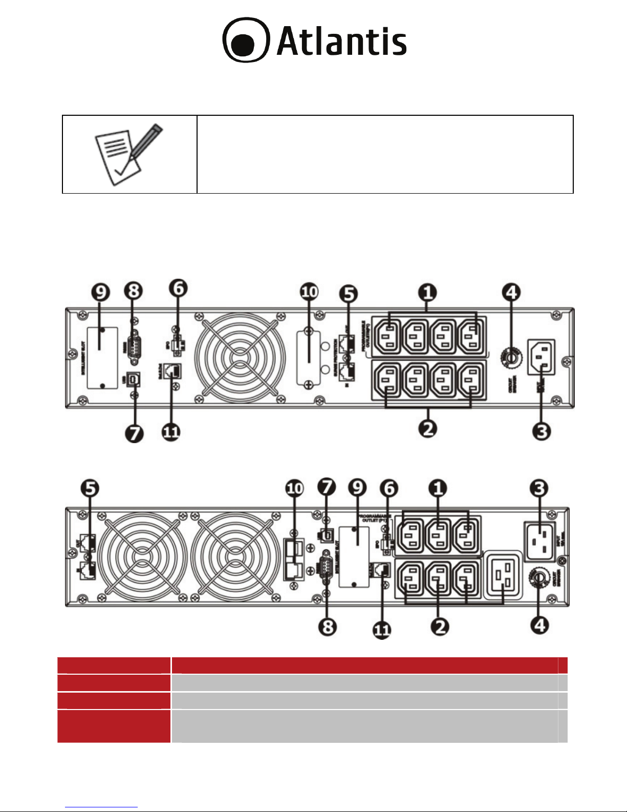
2.1 Pannello Posteriore
Identificativo Utilizzo
1 Uscite programmabili (IEC 320): connettere carichi non critici.
2 Uscite (IEC 320): connettere carichi ritenuti critici.
3 Connettere alla rete elettrica di alimentazione tramite il cavo
fornito.
Page 13
13
4 Input circuit breaker. Circuito di protezione in ingresso.
5 Protezione per Network/Fax/Modem.
6 Connettore EPO: Emergency power off.
7 Porta di comunicazione USB.
8 Porta di comunicazione RS232.
9 Slot per la connessione della scheda SNMP (opzionale).
10 Connettore per battery bank esterno (solo per A03-HP3351-
RC).
11 Interfaccia per gestione battery bank (attiva solo su A03-
HP3351-RC).
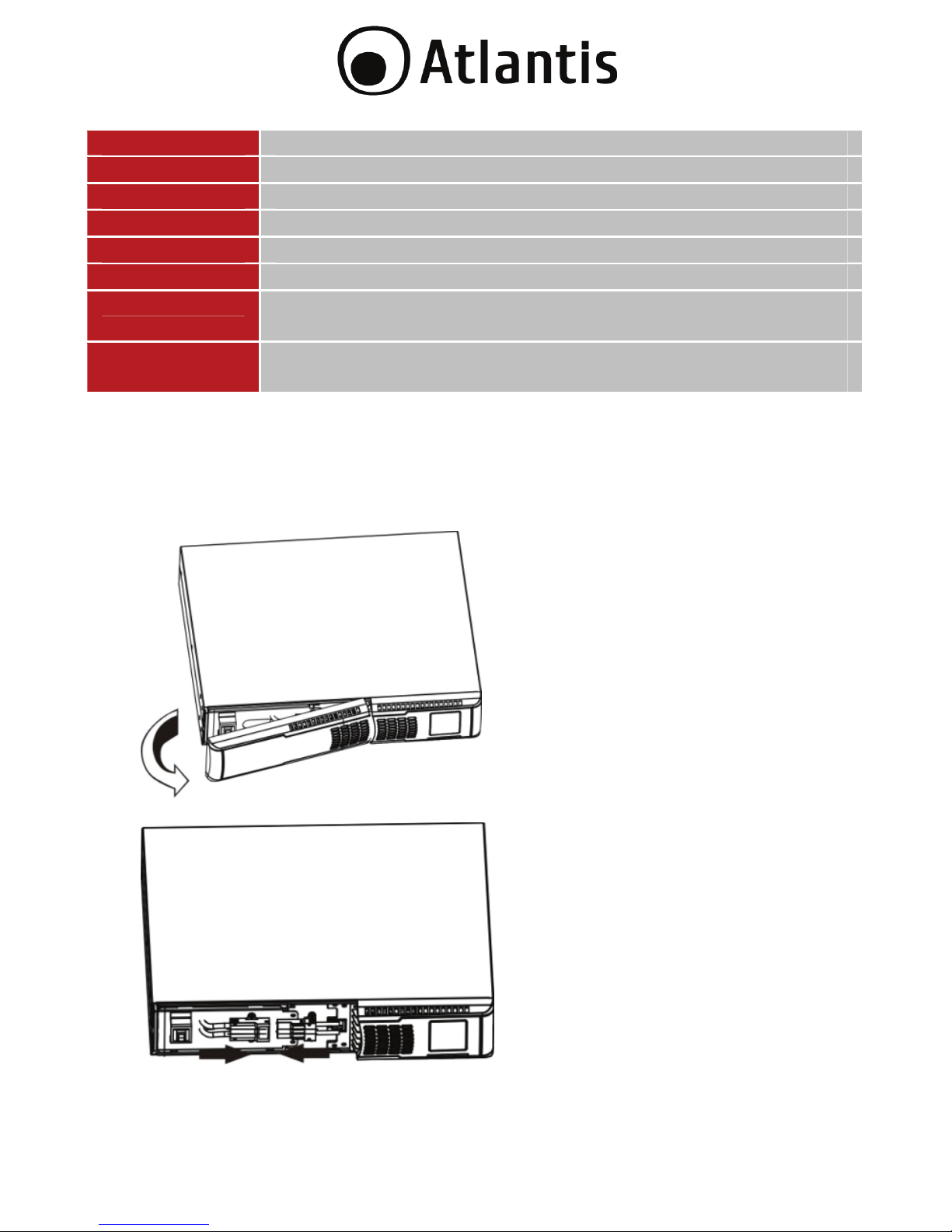
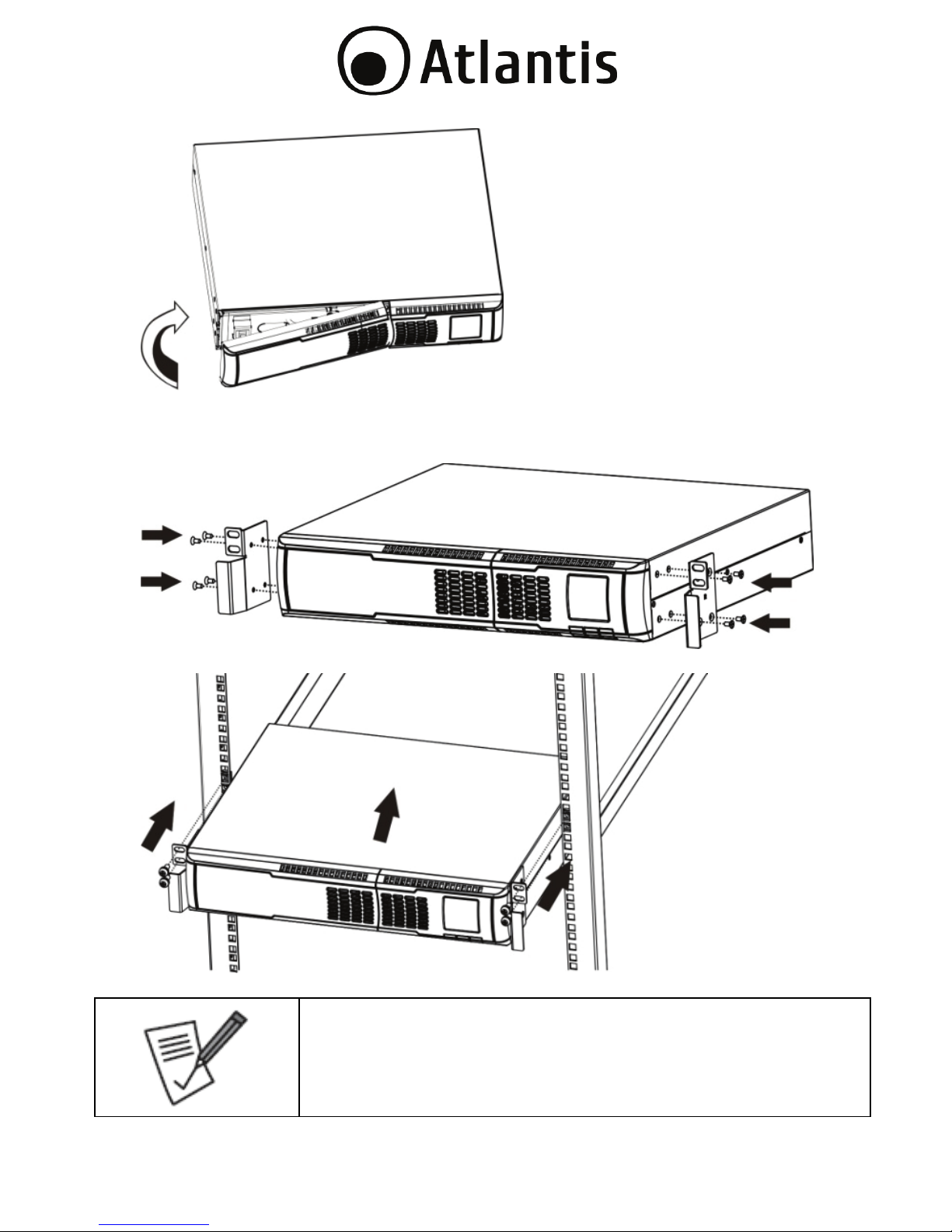
2.2 Installazione
L’UPS viene imballato, per questioni di sicurezza, con il pacco batterie scollegato.
Prima di iniziare è opportuno riconnettere il pacco batterie.
Step 1 (Rimuovere il pannello frontale).
Step 2 (Connettere il pacco batterie, collegando i 2 appositi connettori).
Step 3 (Riposizionare il pannello frontale).
Page 14
14
Installazione su Armadio Rack
Step 1 (Fissare tramite le apposite vite le staffe al prodotto).
Step 2 (Fissare alla struttura Rack).
Il Kit Rack incluso è formato da 2 staffe ed 8 viti per il
fissaggio di queste alla struttura dell’UPS. Eventuali piani,
staffe scorrevoli, viti di fissaggio al Rack sono accessori non
inclusi.
Page 15
15
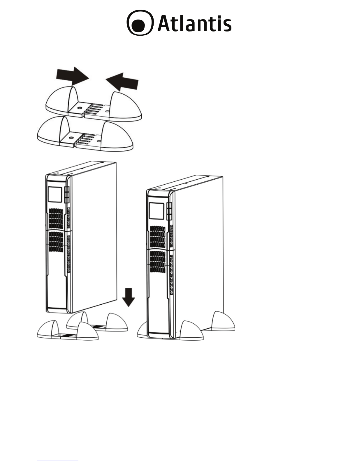
Installazione Tower
Step 1 (montare i 2 piedini di sostegno).
Step 2 (posizionare delicatamente il gruppo sui 2 piedini montati).
Page 16
16
2.3 Setup dell’UPS
Step 1: Collegamento dell’UPS alla rete elettrica
Connettere il cavo schuko fornito all’UPS (Pannello posterione, Indentificativo N°3)
e alla rete elettrica (verificare che questa abbia una corretta messa a terra). Non
utilizzare mai cavi di estensione o prolunghe.
Step 2: Collegamento del carico all’UPS
Nella parte posteriore dell’UPS sono presenti diverse prese IEC320, in numero
variabile secondo il modello. Alcune di queste sono programmabili (si spengono
dopo un tempo impostato, per permettere di salvare l’energia residua delle batterie
per i carichi critici) mentre altre sono sempre attive (l’UPS fornirà tensione in
modalità batteria sino all’esaurimento di queste).
Fatte queste considerazioni è opportuno collegare i carichi, a seconda della loro
criticità, alle prese opportune.
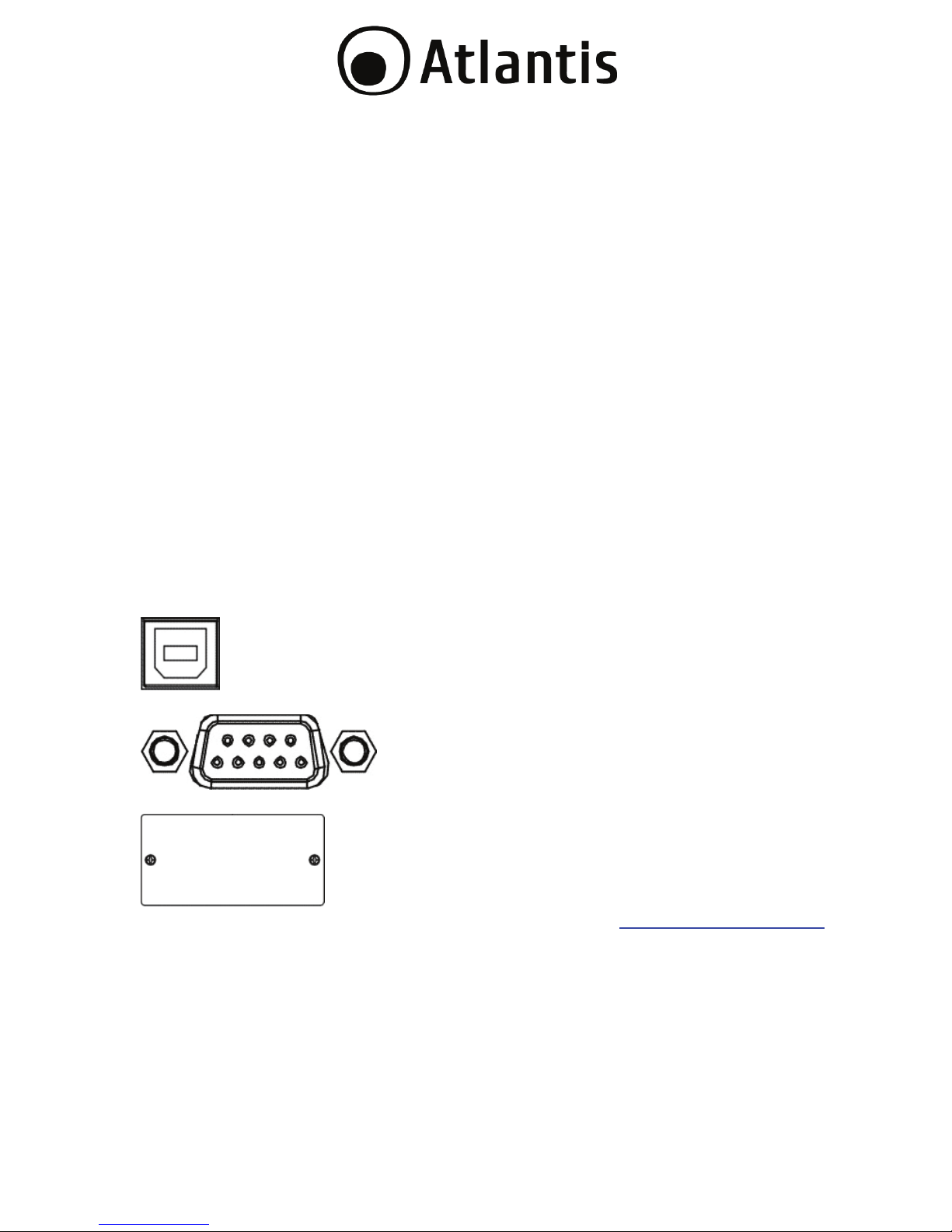
Step 3: Porte di Communicazione
L’UPS integra 2 porte di comunicazione locali (USB/RS232) ed uno slot in cui
inserire la scheda SNMP opzionale.
USB Port
RS232 Port
Intelligent Slot
Tramite il software di gestione (scaricabile all’indirizzo www.atlantis-land.com
) è
possible controllare lo stato di funzionamento dell’UPS e permettere lo spegnimento
controllato del PC collegato tramite RS232/USB.
La scheda SNMP opzionale permette inoltre di gestire l’UPS tramite LAN (anche da
postazioni remote) e permette lo spegnimento di diversi PC in LAN (con il rispettivo
client installato).
Page 17
17
Le porte USB e RS232 non possono funzionare
contemporaneamente.
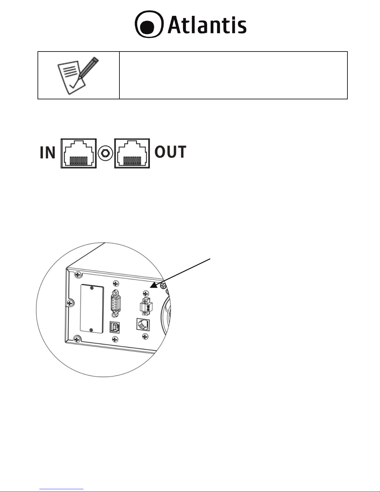
Step 4: Network/Phone
Nella parte posteriore dell’UPS è presente una porta di protezione compatibile con
RJ11/RJ45 (Fax/Phone/Network).
Collegare nella porta IN la linea FAX/Telefonica o il cavo LAN entrante e da OUT
collegare il dispositivo ad un FAX/TELEFONO o periferica di rete.
Step 5: EPO
L’interfaccia EPO permette di spegnere immediatamente l’UPS. Quando il circuito è
chiuso l’UPS può funzionare, quando il circuito è aperto l’UPS si spegne
immediatamente.
Page 18
18
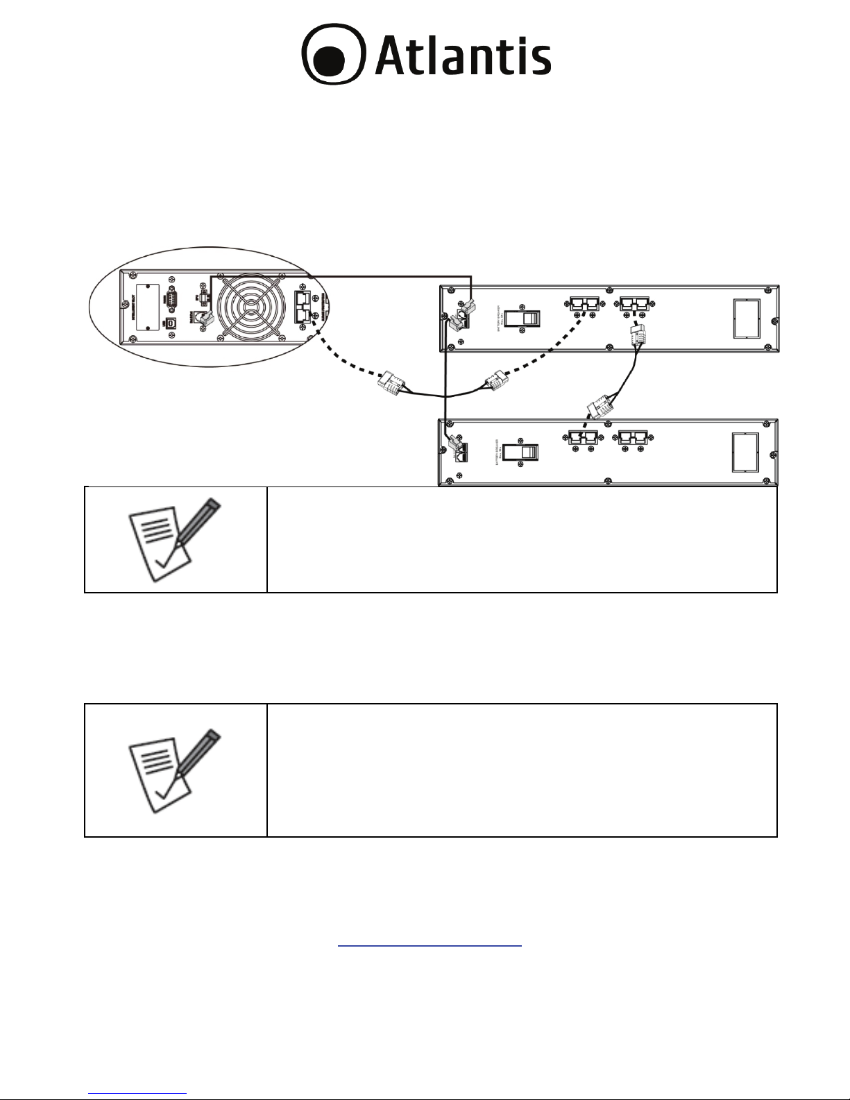
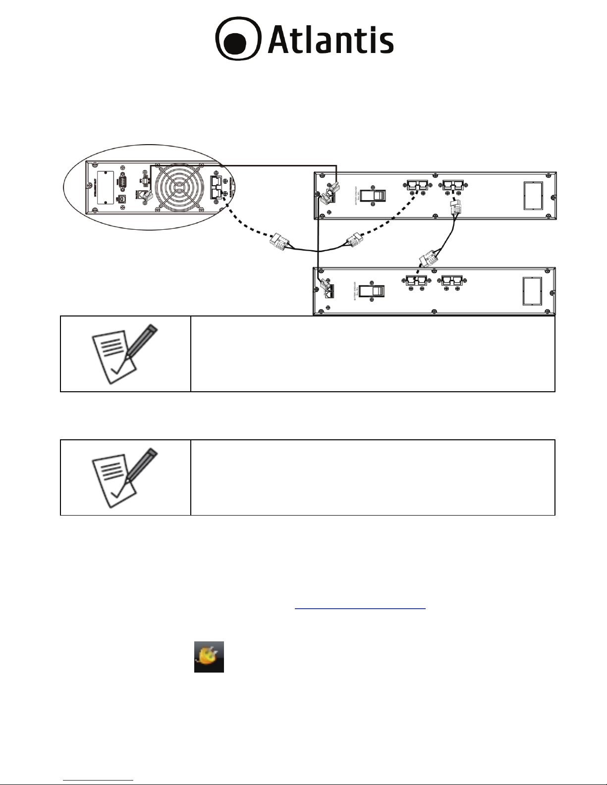
Step 6: Battery Bank Esterno (solo per A03-HP3551-RC)
Collegare il battery bank all’UPS usando l’apposito cavo (Pannello posterione,
Indentificativo N°10). Possono essere messi in cascata sino a 4 battery bank per
offrire lunghi tempi di backup. Va inoltre utilizzato anche il cavo di rilevazione
(Pannello posterione, Indentificativo N°11) fornito col battery bank. Seguire lo
schema di sotto.
Il numero massimo di unità esterne collegabili è 4. Non
superare mai questo limite.
Step 7: Accensione dell’ UPS
Premere il tasto ON/Mute, sul pannello frontale, per circa 2 secondi. L’UPS
emetterà un fischio e partirà la procedura si auto-test della durata di circa 10
secondi. Terminata questa fase l’UPS è pronto al funzionamento.
La batteria verrà caricata durante le prime 5 ore di
funzionamento per raggiungere la massima carica
accumulabile solo dopo qualche ciclo di carica/scarica. La
capacità di backup in questo periodo è limitata e potrebbe
non essere in linea con quanto riportato nella
documentazione.
Step 8: Installazione del software di controllo
E’ opportuno per utilizzare al meglio l’UPS e garantire uno spegnimento controllato
del PC collegato installare il software di gestione.
Scaricare il software da www.atlantis-land.com
alla pagina di prodotto ed
installarlo.
Seguire le istruzioni a schermo per completare l’installazione.
Page 19
19
Il computer verrà riavviato e verrà visualizzate un’icona di avvio rapida ( )
nel system tray.
3.0 UTILIZZO DELL’UPS
Nelle sezioni seguenti verrà illustrato come configurare e utilizzare propriamente il
dispositivo.
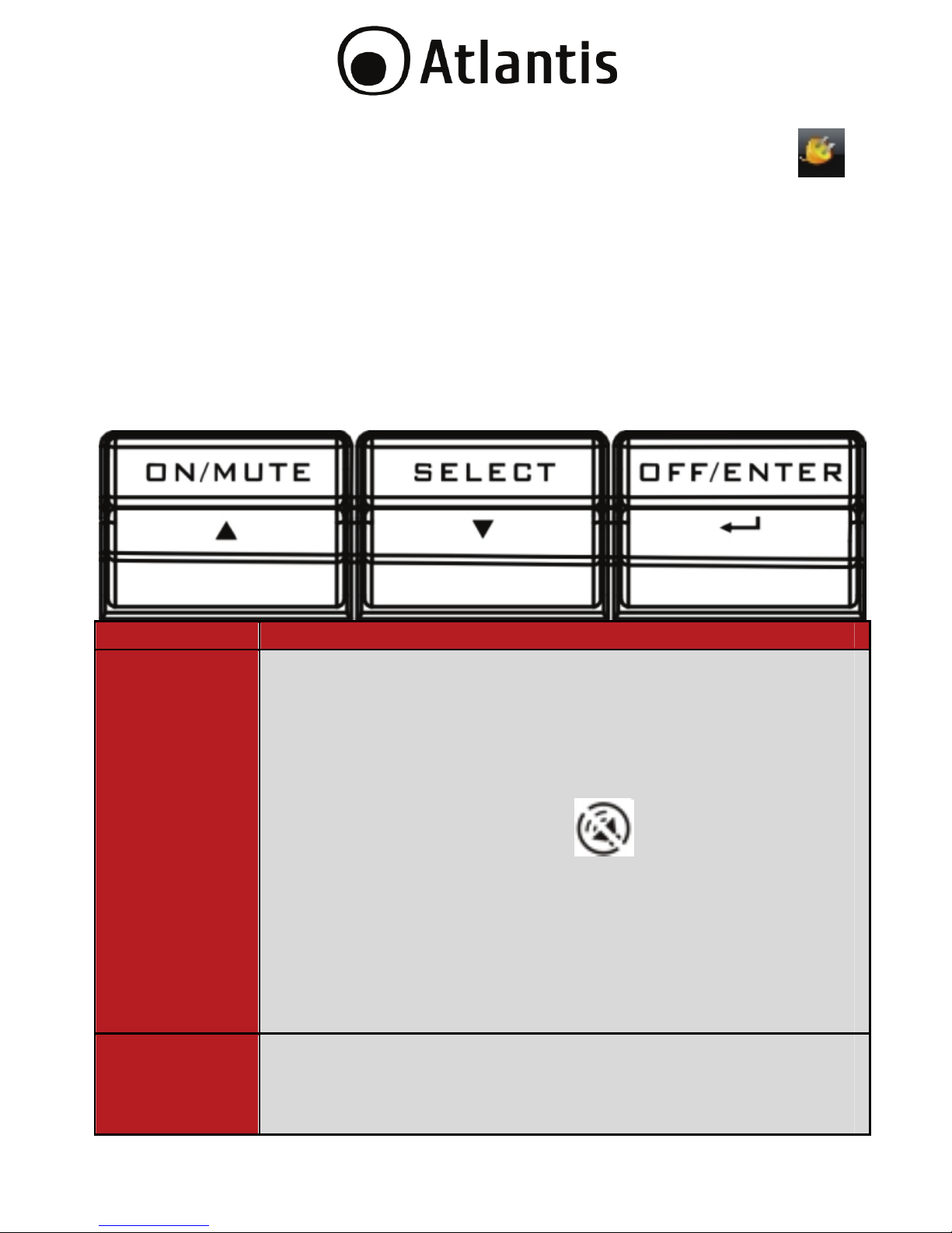
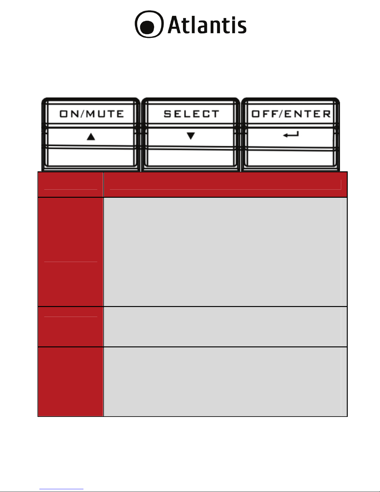
3.1 Bottoni Frontali di Selezione
Bottone Funzione
ON/MUTE
Accensione dell’UPS: Premere per circa 2 secondi il
bottone ON/Mute per accendere il dispositivo.
Silenziare l’allarme acustico: Quando l’UPS va in
modalità batteria emette una segnalazione acustica ogni
10 secondi. Premere (e matenere premuto) questo
bottone per togliere la segnalazione acustica. Sul display
verrà visualizzata l’icona ( ). Il silenziamento non
verrà applicato che per la modalità Batteria.
Up: Premere per visualizzare la scelta precedente.
Self-test mode: Premere (e matenere premuto) questo
bottone per circa 5 secondi (quando l’UPS è acceso) per
attivare la modalità Self-Test. Viene effettuata una
diagnostica (la cui durata è una decina di secondi) sulle
principali funzionalità dell’apparato.
OFF/ENTER
Spegnere l’UPS: Tenere premuto per circa 2 secondi
questo tasto per spegnere il dispositivo.
Conferma: Premere questo bottone per confermare una
scelta quando l’UPS si trova in modalità configurazione
Page 20
20
(settingmode).
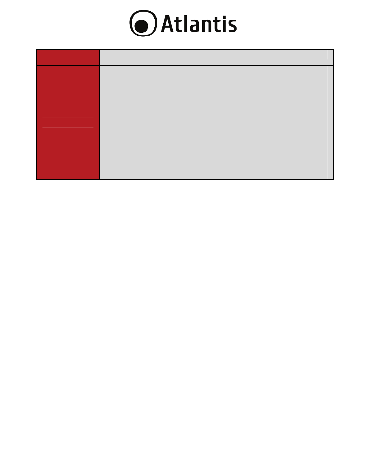
SELECT
Cambio messaggio sull’LCD message: Premere questo
bottone per cambiare l’informazione visualizzata sul
display. Una segnalazione acustica avviserà del
cambiamento avvenuto. In sequenza verranno mostrate le
seguenti informazioni: Voltaggio in Ingresso, Frequenza in
Ingresso, Voltaggio delle Batterie, Voltaggio in Uscita,
Frequenza in Uscita.
Modalità Configurazione (Setting Mode): Quando l’UPS
è spento (ma connesso alla linea elettrica) premere per 10
secondi (sino a che il segnale acustico non è interrotto)
per entrare in modalità configurazione.
Down: Premere per visualizzare la scelta successiva.
Page 21
21
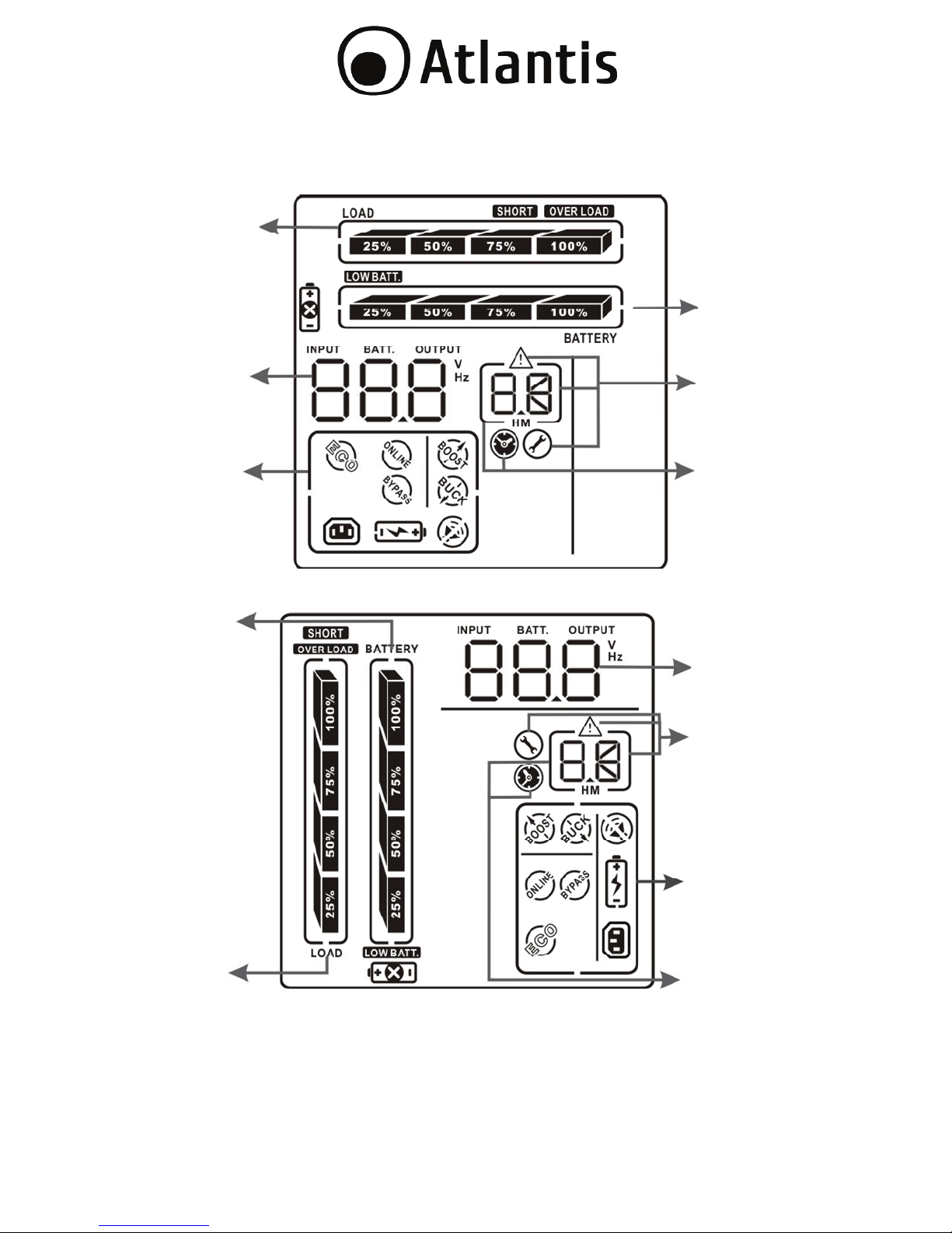
3.2 Panello LCD
Batter
y
Info
Load info
Input/output
and Battery
info
UPS status
Warnin
g
& Fault info/
Setting
operation
Backup
time info
Load info
UPS status
Backup time
info
Input/output
and Battery info
Warnin
g
& Fault I
Setting operation
Battery info
Page 22
22
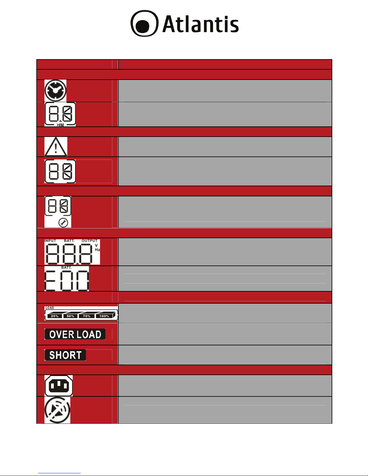
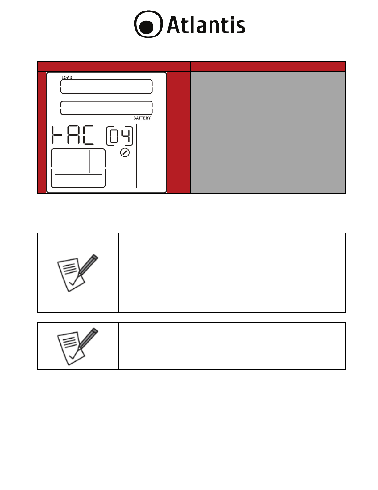
Display Funzione
Backup time information
Indica il tempo di Backup stimato.
Indica il tempo di Backup stimato.
H: ore, M: minuti
Messaggi di Allerta e Malfunzionamento
Indica la presenza di un messaggio di allerta o
malfunzionamento nel dispositivo.
Viene indicato il codice che ha generato
l’errore/allerta/malfunzionamento. Consultare la sezione
3.8 per avere dettagli ulteriori.
Modalità Configurazione (Setting Operation)
Indica che il gruppo è in modalità configurazione (Setting
Operation).
Input/Output & Battery information
Indica il voltaggio/frequenza dell’uscita/ingresso e la
tensione delle batterie. V: voltaggio, Hz: frequenza
Indica il numero di battery bank esterni connessi.
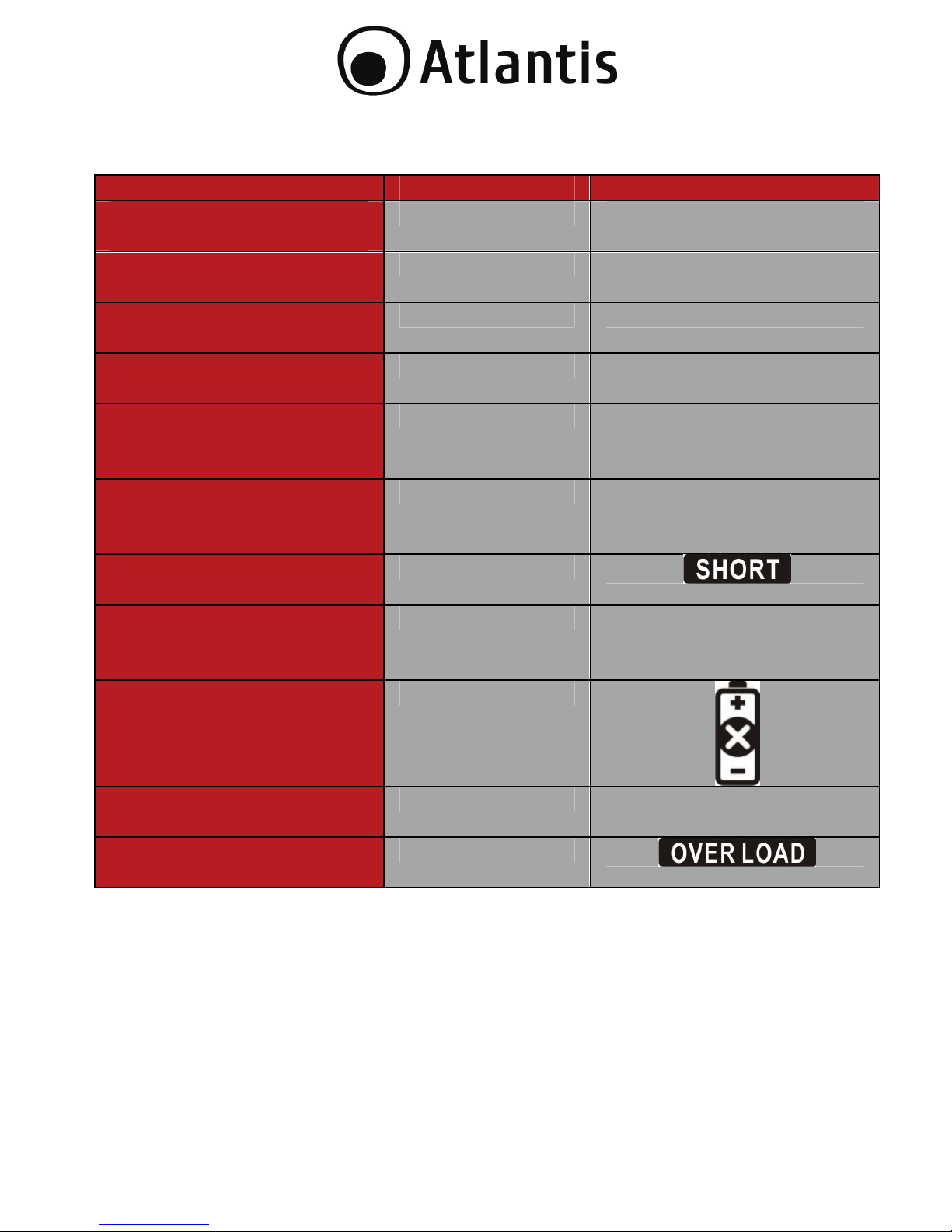
Load information
Indica il livello di carico : 0-25%, 26-50%, 51-75% e 76100%.
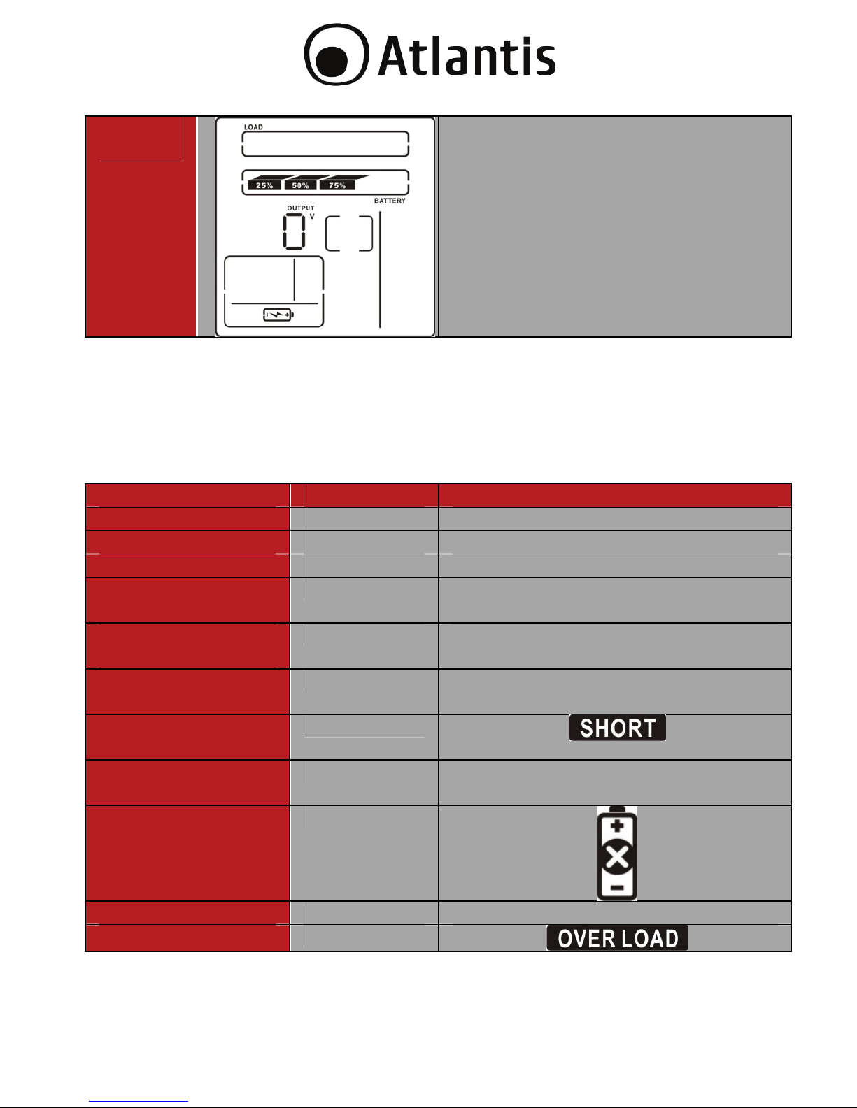
Indica una situazione di sovraccarico.
Indica la presenza di un corto circuito rilevato sul carico
connesso.
UPS status
Indica che le uscite programmabili sono funzionanti.
Indica che l’allarme sonoro è disattivato.
Page 23

23
Indica che il carico è alimentato direttamente dalla rete
elettrica (questa è rintenuta accettabile ed entro i limiti di
tolleranza dal dispositivo).
Indica che il caricatore delle batterie sta funzionando.
L’UPS funziona in modalità boost (AVR) innalzando la
tensione di ingresso.
L’UPS funziona in modalità buck (AVR) abbassando la
tensione di ingresso.
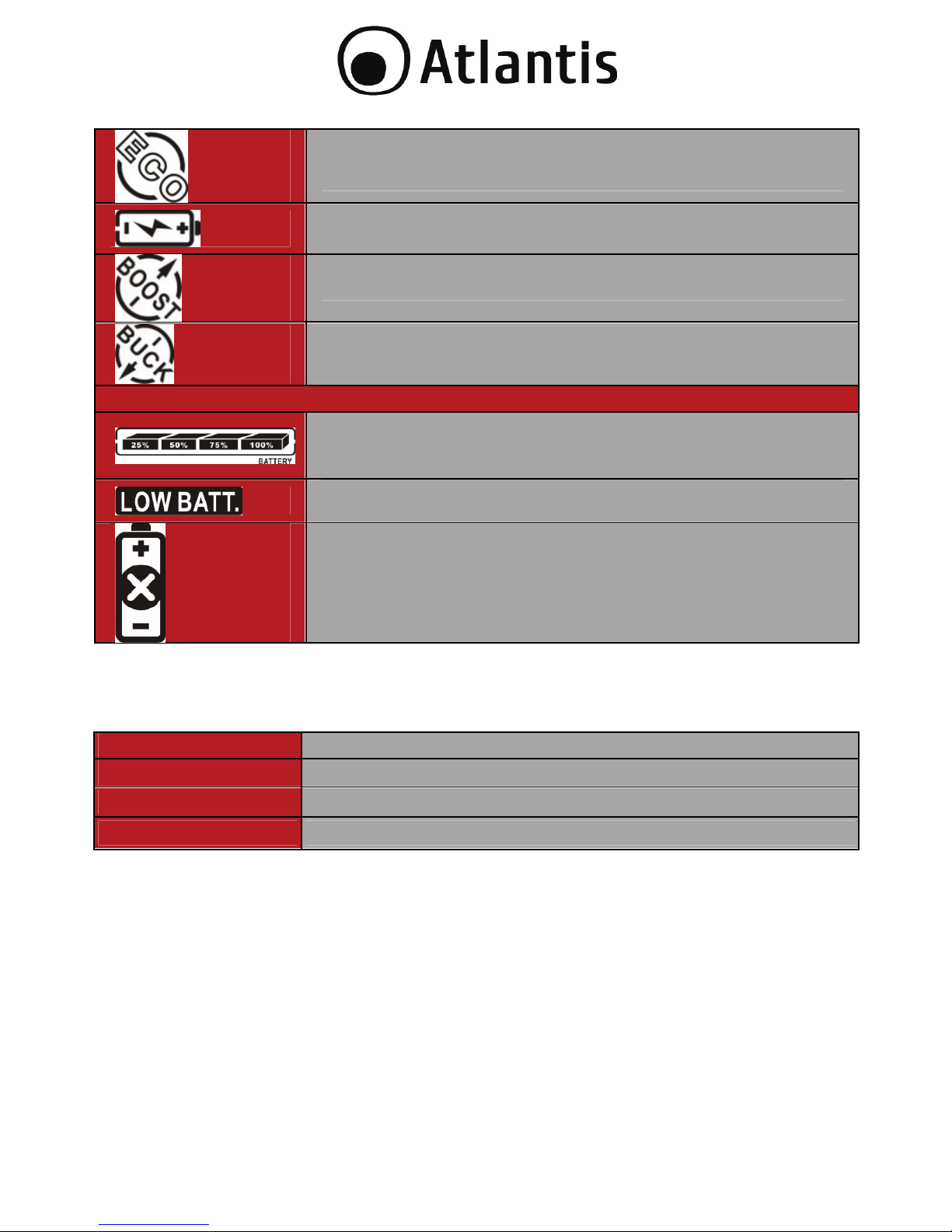
Battery information
Indica il livello di carica delle batterie tra 0-25%, 2650%, 51-75% e 76-100%.
Indica che le batterie hanno un basso livello di carica.
Indica problemi alle batterie.
3.3 Allarmi Acustici
Battery Mode
(Modalità Batteria)
Segnale acustico ogni 10 secondi.
Low Battery
(
Batteria scarica)
Segnale acustico ogni secondo.
Overload
(Sovraccarico)
Segnale acustico 2 volte al secondo.
Fault
(Malfunzionamento)
Segnale acustico ininterrotto.
Page 24
24
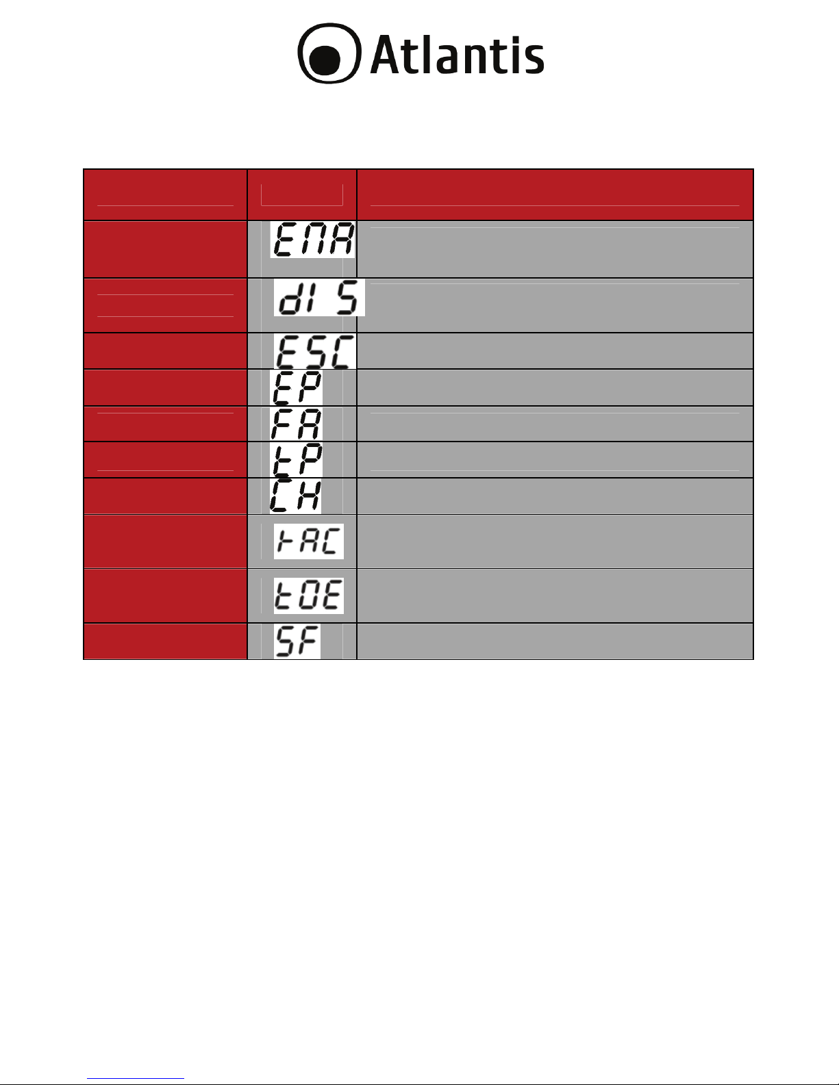
3.4 LCD Display
Abbreviazione Display Significato
ENA
Le USCITE programmabili (IEC) sono
ABILITATE.
DIS
Le USCITE programmabili (IEC) sono
DISABILITATE.
ESC Uscire.
EP EPO.
FA Fan.
TP Temperatura.
CH Caricatore attivo.
RAC
Rack display configurato per modalità Rack
(orizzontale).
TOE
Tower display configurato per modalità Tower
(verticale).
SF Controllare messa a terra o polarità.
Page 25
25
3.5 Modalità Configurazione (UPS Setting)
Si ricorda che i pro
g
rammi disponibili sono 4:
0: Uscita
1: Voltaggio Uscita
2: Abilitazione Uscite (IEC) programmabili
3:Configurazione timing delle Uscite
programmabili
4: Configurazione orientamento Display
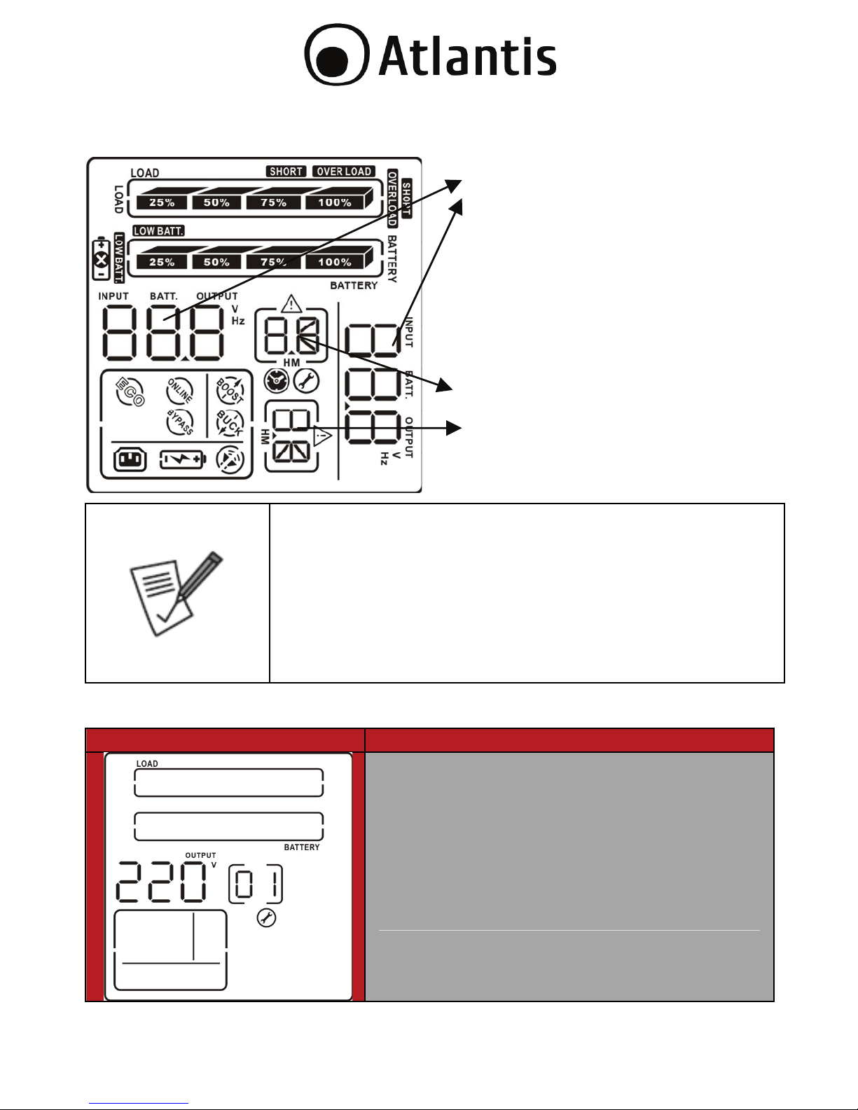
01: Configurazione Voltaggio Uscita (Output voltage setting)
Interfaccia Configurazione
E’ possibile impostare uno dei seguenti
voltaggi in uscita dell’UPS.
208: imposta l’uscita a 208Vac
220: imposta l’uscita a 220Vac
230: imposta l’uscita a 230Vac
240: imposta l’uscita a 240Vac
Questo influenzerà le zone di funzionamento
dell’AVR e la modalità batteria.
Parameters 1
Parameters 2
Page 26
26
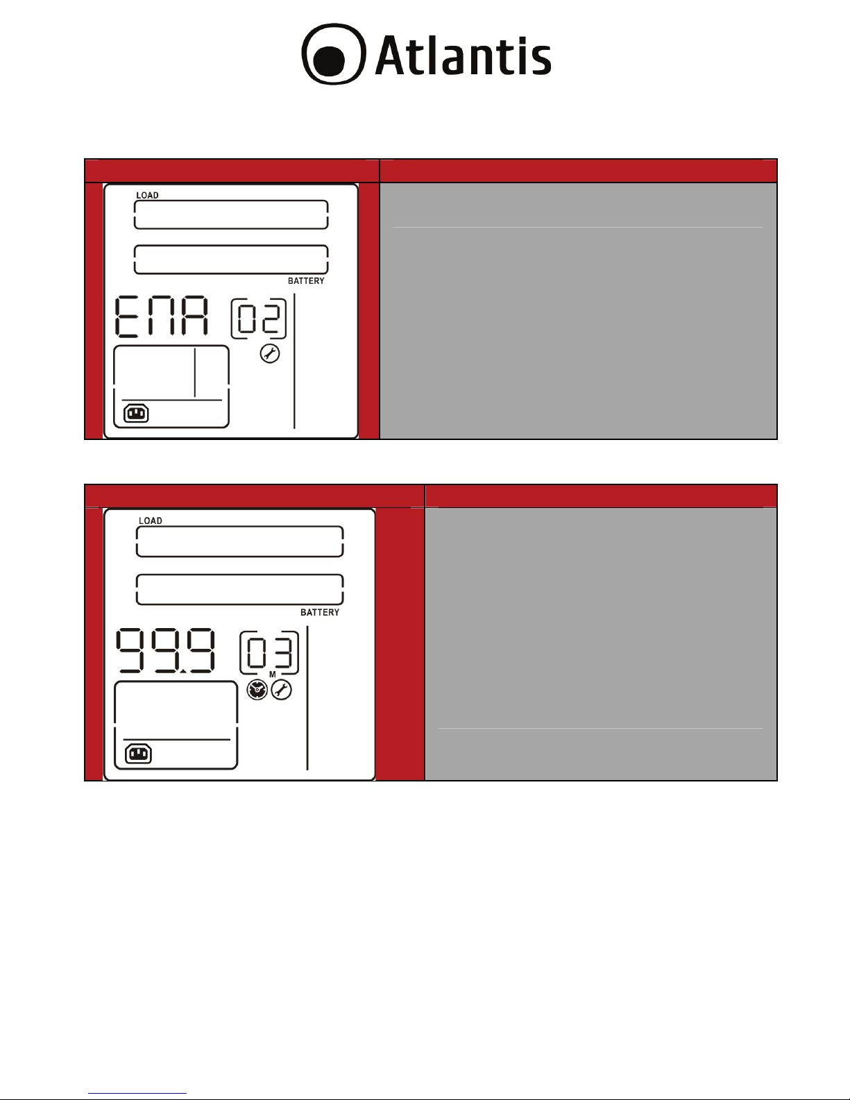
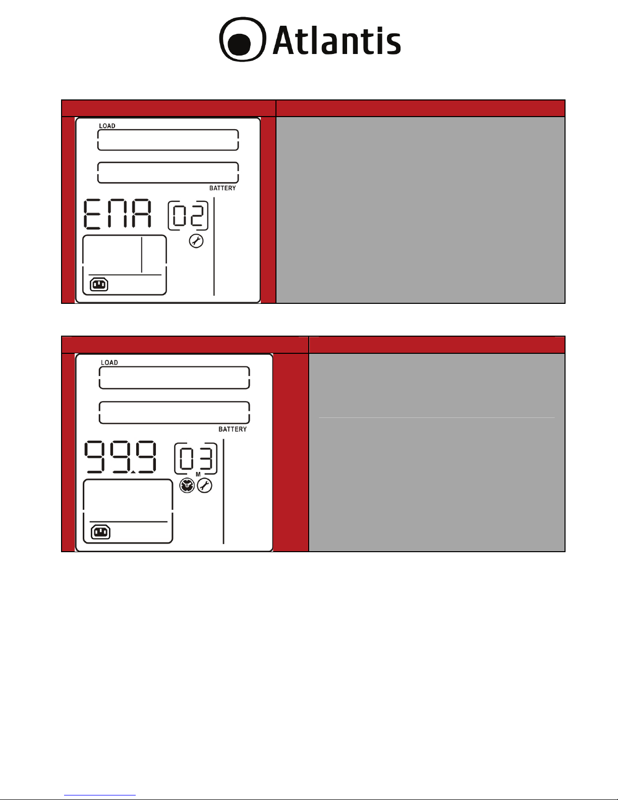
02: Attivazione Uscite Programmabile (Programmable outlets
enable/disable)
Interfaccia Configurazione
ENA: Abilita le uscite (IEC) programmabili.
DIS: Disabilita le uscite (IEC) programmabili.
03: Uscite Programmabile (Programmable outlets setting)
Interfaccia Configurazione
E’ possibile impostare il tempo di
funzionamento in minuti (tra 0-999)
delle uscite (IEC) programmabili. L’UPS
passato tale intervallo, dal
funzionamento in modalità batteria,
smetterà di alimentare queste uscite
per salvare l’energia rimanente
destinandola ai soli carichi critici
connessi alle uscite non programmabili.
Page 27
27
04: Configurazione Orientamento Display (LCD display direction setting)
Interfaccia Configurazione
RAC: Rackdisplay configurato per
modalità Rack (orizzontale).
TOE: Tower display configurato per
modalità Tower (verticale).
00: Uscita Modalità Configurazione (Exit setting)
Premere per uscire dalla modalità configurazione.
Si ricorda che i pro
g
rammi disponibili sono 4:
0: Uscita
1: Voltaggio
2: Abilitazione Uscite programmabili
3: Configurazione timing delle Uscite
programmabili
4: Configurazione orientamento Display
Scollegare il cavo di connessione alla rete elettrica ed
aspettare che il Display sia spento. Alla riaccensione il
dispositivo utilizzerà la configurazione appena impostatata.
Page 28

28
3.6 Esempio di configurazione (UPS Setting)
Si voglia seguire l’esempio seguente per impostare le uscite programmabili per un
funzionamento sino a 3 minuti.
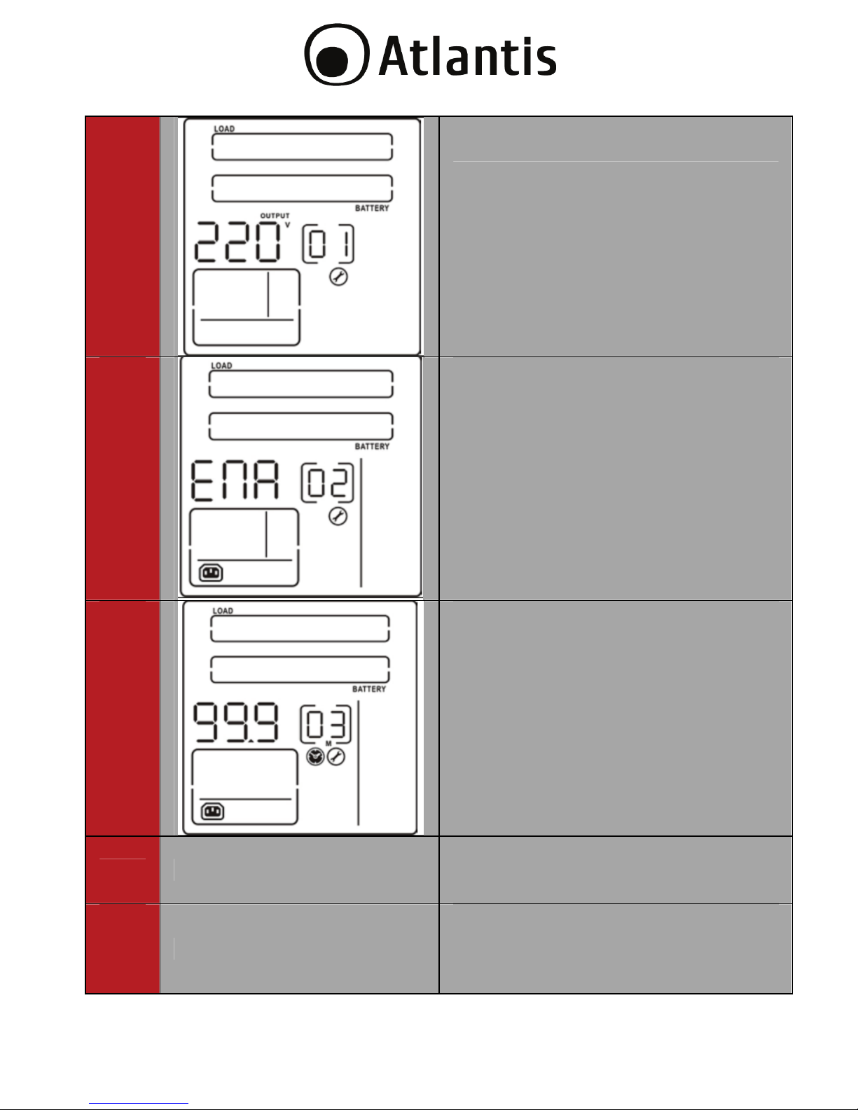
Step LCD Configurazione
1 Prima di entrare in modalità
configurazione l’UPS deve essere
spento (con le batterie connesse) e
collegato alla linea elettrica. Il display
dovrebbe essere come nell’immagine a
fianco.
2 Premere il bottone Select per 10
secondi per entrare in modalità
configurazione (il sistema emetterà un
fischio continuo, solo quando si
interromperà è possibile rilasciare il
pulsante Select).
3
Premere, senza rilasciare, per un
paio di secondi il bottone
(ON/MUTE) per spostarsi tra i vari
programmi disponibili.
Premere OFF/Enter per entrare nel
programma visualizzato (sino a
che il dispositivo non emette un
fischio).
Premere il bottone (ON/MUTE) per
spostarsi tra le opzioni disponibili
nel programma selezionato (sino
a che il dispositivo non emette un
fischio).
Premere OFF/Enter per
confermare i settaggi ed uscire.
Page 29

29
Selezionare il programma 02 e cliccare
su OFF/Enter, cliccare su ON/MUTE
sino a che sul display venga visualizzato
ENA e cliccare OFF/Enter per uscire.
4 Selezionare il programma 03 e cliccare
su OFF/Enter, cliccare su ON/MUTE
sino a che sul display venga visualizzato
3 e cliccare OFF/Enter per uscire. Al
solito ogni bottone va premuto sino a
che il dispositivo non emette un fischio.
5
Selezionare il programma 04 e cliccare
su OFF/Enter per uscire. Al solito ogni
bottone va premuto sino a che il
dispositivo non emette un fischio.
6
Scollegare il cavo di connessione alla
rete elettrica ed aspettare che il Display
sia spento. Alla riaccensione il
dispositivo utilizzerà la configurazione
appena impostatata.
Page 30

30
3.7 Modalità Operative
Step LCD Descrizione
ECO
mode
Quando la rete elettrica in ingresso è
dentro la soglia di tolleranza, l’uscita è
alimentata (connessa) direttamente
all’ingresso.
ECO è l’acronico di Efficiency Corrective
Optimizer. In questo modo, quando le
batterie sono completamente cariche
l’UPS spegne anche la ventilazione
forzata per risparmiare al massimo il
consumo elettrico.
Buck
(AVR)
Quando il voltaggio in ingresso è in
finestra ma più alto di quello atteso il
circuito AVR lo riduce (Buck)
rendendone il valore più vicino a quello
atteso.
Boost
(AVR)
Quando il voltaggio in ingresso è in
finestra ma più basso di quello atteso il
circuito AVR lo aumenta (Boost)
rendendone il valore più vicino a quello
atteso.
Page 31

31
Battery Quando il voltaggio in ingresso è fuori
finestra o assente, l’UPS alimenta il
carico utilizzando l’energia delle
batterie. In questo caso emette un
suono ogni 10 secondi.
Standby
Mode
L’UPS è spento e nessun carico
connesso è alimentato, ma se collegato
alla rete elettrica l’UPS può caricare, se
necessario, le batterie.
Page 32
32
3.8 Tabella Errori
Malfunzionamento Indicativo errore Icona
Problemi sul BUS (Bus
start fail)
01 x
Tensione elevata sul Bus
(Bus over)
02 x
Tensione bassa sul Bus
(Bus over)
03 x
Problemi sul all’Inverter
(Inverter soft start fail)
11 x
V
oltaggio Elevato
sull’inverter (Inverter
voltage high)
12 x
V
oltaggio
Bassosull’inverter
Inverter voltage Low
13 x
Corto Circuito in uscita
(Inverter output short)
14
V
oltaggio Batterie
Elevato (Battery voltage
too high)
27 x
V
oltaggio delle batterie
basso (Battery voltage
too low)
28
Temperatura Eccessiva
(Over temperature)
41 x
Sovraccarico
(Over load )
43
Page 33
33
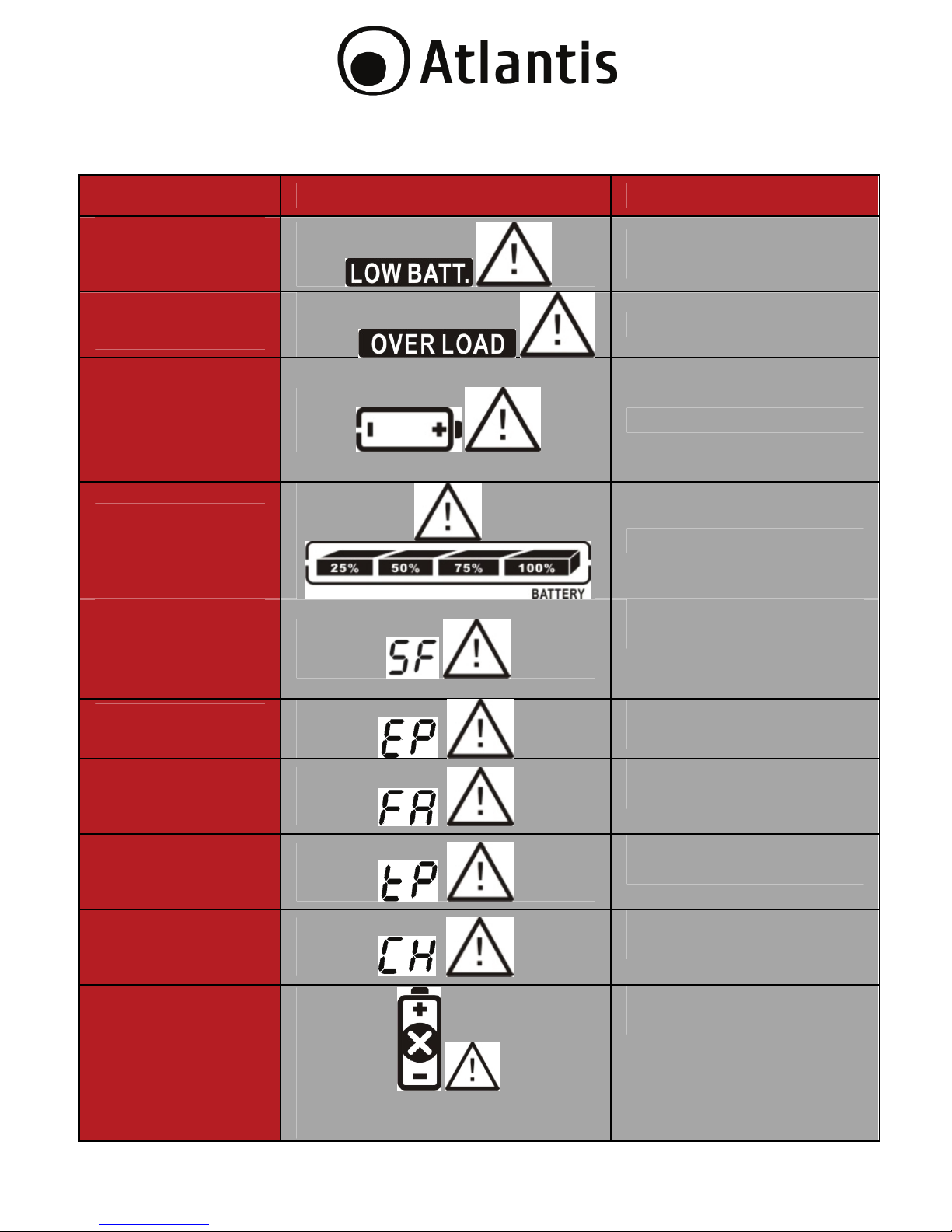
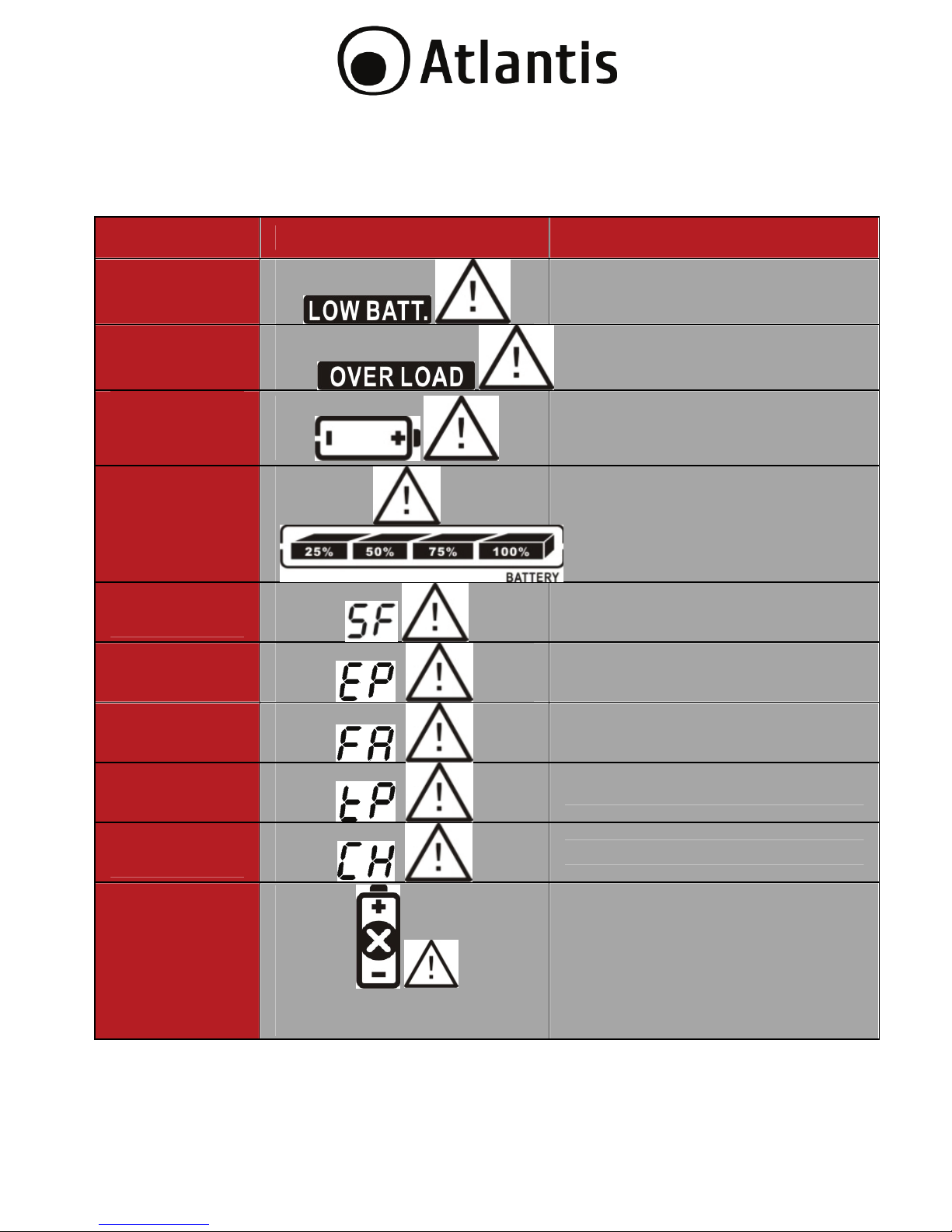
3.9 Allarmi
Allarme Icon (Lampeggiante) Alarme Sonoro
Batterie Scarica
(Low
Battery)
Suono ogni secondo.
Sovraccarico
(Overload)
Suono 2 volte al secondo.
Batterie non
connessa
(Battery
is not
connected)
Suono ogni secondo.
Sovraccarico
delle batterie
(Overcharge)
Suono ogni secondo.
Connessione a
terra/fase
errata (Site
wiring fault)
Suono ogni secondo.
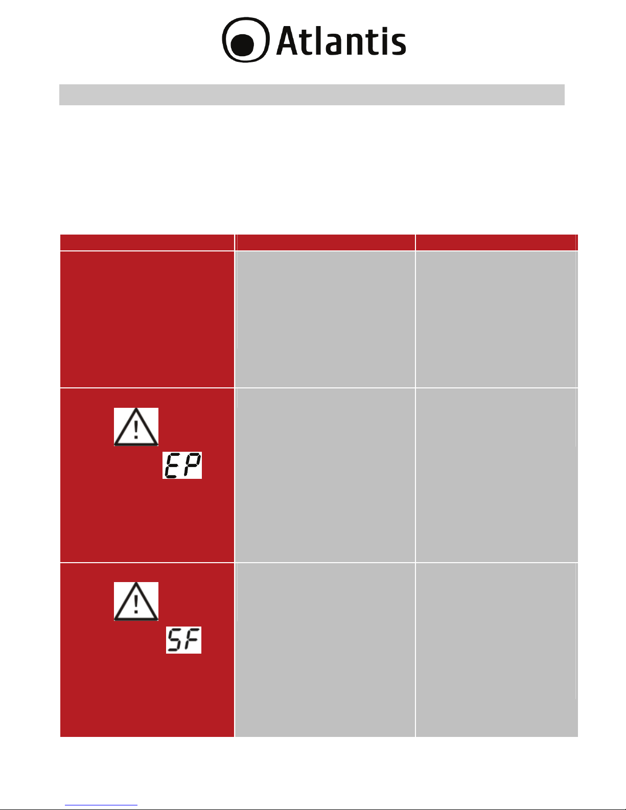
EPO attiva (EPO
enable)
Suono ogni secondo.
Problemi
Ventola (Fan
Failure)
Suono ogni secondo.
Temperatura
elevate (Over
temperature)
Suono ogni secondo.
Caricatore
guasto (Charger
failure)
Suono ogni secondo.
Batteria Guasta
(Battery Fault)
Suono ogni secondo.
Page 34
34
APPENDICE A: Risoluzione dei problemi e Supporto
Questo capitolo illustra come identificare e risolvere eventuali problemi riscontrati
con l’utilizzo del dispositivo.
A.1.1 Problematiche dell’UPS
I LEDs ed i segnali acustici sono un utile strumento per individuare eventuali
problemi, osservandone lo stato e/o ascoltandone il tipo di beep è possibile
individuare velocemente un eventuale malfunzionamento.
Situazione Controllo Soluzione
Nessuna indicazione ma
allarmi in presenza di
rete elettrica.
1. Il cavo di alimentazione è
connesso alla rete
elettrica?
2. Il cavo di alimentazione è
collegato all’UPS?
1. Accertarsi che il cavo di
alimentazione sia
propriamente collegato
alla rete elettrica.
2. Connettere il cavo di
alimentazione nel plug
AC dell’UPS.
Sul display è visualizzata
l’icona e il codice
di avviso è
lampeggiante mentre
viene riprodotta una
segnalazione acustica (1
beep al secondo).
La funzione EPO è attiva. Chiudere il circuito EPO
per disabilitare la funzione
EPO.
Sul display è visualizzata
l’icona e il codice
di avviso è
lampeggiante mentre
viene riprodotta una
segnalazione acustica (1
beep al secondo).
Controllare la messa a terra
o provare ad invertire il verso
della presa elettrica.
1. Invertire la polarità.
2. Chiamare un elettricista
e fare controllare
l’impianto elettrico in
caso il problema
persista.
Page 35
35
Sul display è visualizzata
l’icona e l’icona
è
lampeggiante mentre
viene riprodotta una
segnalazione acustica (1
beep al secondo).
Le batterie interne e/o
esterne non sono collegate
propriamente.
Controllare che le batterie
siano propriamente
collegate.
Si ricorda che l’UPS viene
imballato, per questioni di
sicurezza, con le batterie
scollegate. Prima di
iniziare è opportuno
riconnettere il pacco
batterie. Controllare la
sezione 2.2
V
iene visualizzato il
messaggio di errore
N°27 e l’icona è
accesa mentre viene
riprodotta una
segnalazione acustica
continua.
Il voltaggio delle batterie è
troppo alto oppure il
caricatore è guasto.
Chiamare l’assistenza
tecnica di Atlantis.
V
iene visualizzato il
messaggio di errore
N°28 e l’icona è
accesa mentre viene
riprodotta una
segnalazione acustica
continua.
Il voltaggio delle batterie è
troppo basso oppure il
caricatore è guasto.
Chiamare l’assistenza
tecnica di Atlantis.
Sul display è visualizzata Controllare il carico
verificando di non essere in
Sconnettere parte del
carico.
Page 36

36
l’icona e l’icona
è
lampeggiante mentre
viene riprodotta una
segnalazione acustica (2
beep al secondo).
condizioni di overload.
V
iene visualizzato il
messaggio di errore
N°43 e l’icona
è accesa
mentre viene riprodotta
una segnalazione
acustica continua.
L’UPS si spegne
automaticamente a causa di
un overload continuativo.
Sconnettere parte del
carico e riavviare l’UPS.
V
iene visualizzato il
messaggio di errore
N°14 mentre viene
riprodotta una
segnalazione acustica
continua.
L’UPS si spegne
automaticamente a causa di
un corto circuito in uscita.
Controllare il carico ed i
circuiti di distribuzione
(cavi) e rimuovere la
causa del corto circuito.
V
iene visualizzato il
messaggio di errore
N°2/3/4/11/12/13 o 41
mentre viene riprodotta
una segnalazione
acustica continua.
Errore interno al dispositivo. Chiamare l’assistenza
tecnica di Atlantis.
La durata delle batterie
non è soddisfacente.
1. Le batterie non sono
completamente cariche.
2. Le batterie sono vicine al
termine del loro ciclo di
vita.
1. Ricaricare l’UPS per
almeno 10 ore.
2. Rimpiazzare le batterie
(come da Appendice
seguente).
Sul display è visualizzata La ventola è bloccata o
guasta.
Controllare la ventola e
rimuovere eventualie
Page 37

37
l’icona e l’icona
è lampeggiante
mentre viene riprodotta
una segnalazione
acustica (1 beep al
secondo).
polvere o oggetti che ne
ostruiscono il flusso d’ari.
In caso il problema
persista chiamare
l’assistenza tecnica di
Atlantis.
Q
uando la rete è assente
o fuori finestra di
funzionamento tollerata
il carico e l’UPS si
spengono.
Controllare che il carico non
abbia un PFC attivo.
L’UPS va in protezione per
evitare di guastarsi a
causa della tipologia di
carico collegato (PFC
Attivo). Potrebbe essere
necessario un UPS di
maggiore potenza.
A.1.2 Batterie
Domanda Risposta
Cos’è il Backup
time?
E’ la durata cui l’UPS può mantenere attivo il carico ad esso
collegato prima che le batterie siano completamente scariche.
T
ale durata, ovviamente, dipende dal tipo di carico.
Controllare nella sezione alle fine del manuale.
Che tipo di batterie
sono incluse
nell’UPS?
Le batterie utilizzate in serie sono:
2 x 12VDC- 7A/h nell’A03-HP1101-RC
2 x 12VDC- 9A/h nell’A03-HP1501-RC
4 x 12VDC- 7A/h nell’A03-HP2001-RC
6 x 12VDC- 7A/h nell’A03-HP3351-RC
Ogni quanto vanno
cambiate?
Dipende dal tipo di utilizzo. E’ buona norma testare
periodicamente l’UPS per controllare lo stato di deterioramento
delle batterie.
Si raccomanda di sostituire le batterie una volta all’anno.
Dove posso trovare
le batterie per la
sostituzione?
1. In un qualunque negozio specializzato.
2. Chiederle direttamente all’assistenza tecnica di Atlantis:
2 x 12VDC- 7A/h nell’A03-HP1101-RC
2 x 12VDC- 9A/h nell’A03-HP1501-RC
4 x 12VDC- 7A/h nell’A03-HP2001-RC
Page 38

38
6 x 12VDC- 7A/h nell’A03-HP3351-RC
Le Batterie
consentono una
durata non in linea
con quanto
riportato nella
tabella (Backup
Time).
1. Le condizioni ambientali possono alterare sensibilmente
tali valori.
2. Andrebbero effettuati almeno 5 cicli di carica/scarica
prima di arrivare ad un uso ottimale.
3. L’UPS integra un circuito di controllo che evita di
scaricare completamente la batteria.
4. Dopo un anno prendere in considerazione l’idea di
sostituire la batterie prossime all’esaurimento.
A.1.3 Problematiche del Software ViewPower
Situazione
A
zione Correttiva
Come Installo il
software in
dotazione?
Una volta effettuato l’avvio dell’UPS connetterlo al PC tramite il
cavo USB in dotazione. Il PC provvederà al rilevamento del
dispositivo ed alla sua corretta installazione. A questo punto
scaricare dal sito (www.atlantis-land.com) il software di
gestione.
Il Software di
gestione non rileva
l’UPS. Cosa posso
fare?
1. Verificare che il cavo sia correttamente connesso.
2. Utilizzare il cavo fornito nella confezione.
3. Il software di gestione utilizza un IP della classe
192.168.5.X. Se il PC è n LAN in una classe identica
potrebbero esserci dei conflitti.
Che accuratezza
hanno le rilevazioni
visualizzate dal
software?
Certamente le precisione è soddisfacente per il tipo di
applicazioni in ambito SOHO. Essendo il dispositivo di tipo
elettrico (e non elettronico) non può produrre un’accuratezza
elevata (tolleranze dell’ordine del 5-10% sono pertanto
assolutamente normali).
A.1.4 Varie
Domanda Risposta
Il Voltaggio
misurato all’uscita
dell’UPS (in
modalità Inverter)
è errato.
Cambiare il multimetro con cui si effettua la rilevazione con un
multimetro adeguato (True RMS). Solo questi ultimi possono
leggere in maniera corretta un’uscita stepwave.
Page 39
39
A.1.5 Conservazione
Le batterie sostituite vanno
considerate come un
RIFIUTO TOSSICO e
trattate di conseguenza.
Prima di immagazzinare l’UPS è opportuno effettuare un ciclo completo di ricarica
delle batterie di almeno 5 ore (accendere l’UPS dopo averlo collegato alla linea
elettrica). Immagazzinare l’UPS nel suo imballo originale in un ambiente fresco ed
asciutto. Ricaricare le batterie secondo lo schema di sotto:
Temperatura Frequenza di Ricarica
T
empo per la ricarica
-25°C - 40°C Ogni 3 mesi 1-2 ore
40°C - 45°C Ogni 2 mesi 1-2 ore
A.1.6 Supporto Offerto
Per qualunque altro problema o dubbio sul funzionamento del prodotto, è possibile
contattare il servizio di assistenza tecnica Atlantis tramite l’apertura di un ticket online sul portale http://www.atlantis-land.com/ita/supporto.php
.
Nel caso non fosse possibile l’accesso al portale di supporto, è altresì possibile
richiedere assistenza telefonica al numero 02/ 78.62.64.37 (consultare il sito per
verificare gli orari in cui il servizio viene erogato).
Per esporre eventuali richieste di supporto prevendita o richieste di contatto , si
invita ad utilizzare gli indirizzi mail info@atlantis-land.com
oppure
prevendite@atlantis-land.com.
Atlantis SpA
Via S. Antonio, 8/10
20020 Lainate (MI)
Fax: +39.02.78.62.64.39
Website: http://www.atlantis-land.com
Email: info@atlantis-land.com
Page 40
40
APPENDICE B: Cambio delle Batterie
Questo dispositivo permette il cambio delle batterie interne
senza la necessità di interrompere il funzionamento del
dispositivo (mantenendo quindi il carico funzionante). In
questo caso, in caso di problemi alla rete elettrica, l’UPS
non potrà garantire la corretta alimentazione al carico
collegato.
Prima di iniziare è opportune considerare questa come
un’operazione delicata che va fatta da personale
specializzato.
Seguire tutte le precauzione seguenti:
Nell’UPS è installata una batteria di accumulatori che è
fonte di energia, per cui all’interno del gruppo vi sono delle
tensioni pericolose presenti anche a gruppo spento e/o
scollegato dalle rete elettrica.
Prima di effettuare una qualunque operazione di
manutenzione e/o spostamento dell’apparato è consigliabile
spegnere il dispositivo (tasto OFF/Enter) e scollegare il
pacco batterie interno. I condensatori presenti possono
comunque aver accumulato energia, prestare la massima
attenzione.
La batteria dell’UPS ha 1 anno di garanzia.
Qualora venga sostituita la batteria seguire le seguenti
precauzioni:
non indossare orologi, anelli o oggetti di metallo
impugnare attrezzi con materiale isolante
indossare guanti di gomma e stivali
non appoggiare attrezzi o parti di metallo sopra la
batteria
All’uscita dell’UPS può esserci una tensione di 220V anche
quando il gruppo è scollegato dalla rete. Prima di
iniziare la sostituzione della batteria è opportuno
spegnere l’UPS e staccarlo dalla rete elettrica.
Page 41
41
Benché il gruppo supporti la modalità Hot Swap è
consigliabile spegnere e scollegare tutti i carichi,
spegnere il gruppo e staccarlo dalla linea elettrica.
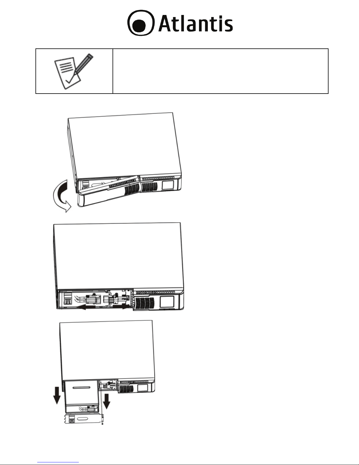
Sostituzione del pacco batterie
Step 1 (Rimuovere il pannello frontale).
Step 2 (Sconnettere il pacco batterie, scollegando i 2 appositi connettori).
Step 3 (Rimuovere le 2 viti ed estrarre il pacco batterie).
Page 42

42
Step 4 (Rimuovere la copertura superiore del battery-box e sostituire le batterie
con batterie nuove equivalenti). Si veda il paragrafo seguente.
Step 5 (Riposizionare delicatamente il battery-box nel proprio alloggiamento).
Step 6 (Connettere il pacco batterie, collegando i 2 appositi connettori.
Riposizionare il pannello frontale).
.
Page 43
43
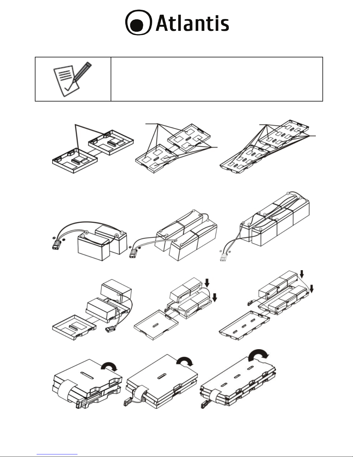
Assemblaggio del Battery Kit Assembly
Il pacco batteria va rimosso dall’UPS, va aperto e vanno
cambiate le batterie e va poi nuovamente inserito nell’UPS.
Seguire la procedura seguente per il cambio delle batterie.
Step 1 (Rimuovere le batterie esauste).
Step 2 (Connettere le batterie seguendo gli schemi sotto riportati, diversi a
seconda del numero di batterie utilizzatae dal dispositivo).
Step 3 (Appoggiare le batterie ad uno dei 3 supporti plastici).
Step 4 (Chiudere il pacco batterie)..
Page 44

44
Copyright
The Atlantis logo is a registered trademark of Atlantis SpA. All other names
mentioned mat be trademarks or registered trademarks of their respective owners.
Subject to change without notice. No liability for technical errors and/or omissions.
CE Mark Warning
In a domestic environment, this product may cause radio interference, in which
case the user may be required to take adequate measures.
This manual contains important safety instructions. Please follow all instructions
carefully during installation. Read this manual thoroughly before attempting to
unpack, install or operate.
Caution: Any changes or modifications to the equipment not expressly approved
by the party responsible for compliance could void the user’s authority to operate
the equipment.
Shielded interface cables and AC power cords, if any, must be used in order to
comply with the emission limits.
Caution: To prevent the risk of fire or electric shock, install in a temperature and
humidity controlled indoor area, free of conductive contaminants.
Caution: Risk of electric shock, do not remove the cover. No user serviceable
parts. Refer servicing to qualified service personnel.
Caution: Risk of electric shock, hazardous live parts inside this UPS can be
energized from the battery supply even when the input AC power is disconnected.
Caution: Risk of electric shock, Battery Circuit is not isolated from AC input,
hazardous voltage may exist between battery terminals and ground. Test before
touching.
Caution: The UPS is designed to be for use with computer loads only. Do not
connect a laser printer to the outlets.
Caution: Do not try to repair the unit yourself, contact your local supplier or your
warranty will be void.
IMPORTANT SAFETY INSTRUCTIONS
Please comply with all warnings and operating instructions in this manual strictly.
Save this manual properly and read carefully the following instructions before
installing the unit. Do not operate this unit before reading through all safety
information and operating instructions carefully
Transportation
Please transport the UPS system only in the original package to protect against
shock and impact.
Page 45

45
Preparation
Condensation may occur if the UPS system is moved directly from cold to warm
environment. The UPS system must be absolutely dry before being installed. Please
allow at least four (5) hours for the UPS system to acclimate the environment.
Do not install the UPS system near water or in moist environments.
Do not install the UPS system where it would be exposed to direct sunlight or near
heater.
Do not block ventilation holes in the UPS housing.
Installation
Do not connect appliances or devices which would overload the UPS system (e.g.
laser printers) to the UPS output sockets.
Place cables in such a way that no one can step on or trip over them.
Do not connect domestic appliances such as hair dryers to UPS output sockets.
The UPS can be operated by any individuals with no previous experience.
Connect the UPS system only to an earthed shockproof outlet which must be easily
accessible and close to the UPS system.
Please use only VDE-tested, CE-marked mains cable (e.g. the mains cable of your
computer) to connect the UPS system to the building wiring outlet (shockproof
outlet).
Please use only VDE-tested, CE-marked power cables to connect the loads to the
UPS system.
When installing the equipment, it should ensure that the sum of the leakage current
of the UPS and the connected devices does not exceed 3.5mA.
Operation
Do not disconnect the mains cable on the UPS system or the building wiring outlet
(shockproof socket outlet) during operations since this would cancel the protective
earthing of the UPS system and of all connected loads.
The UPS system features its own, internal current source (batteries). The UPS
output sockets or output terminals block may be electrically live even if the UPS
system is not connected to the building wiring outlet.
In order to fully disconnect the UPS system, first press the OFF/Enter button to
disconnect the mains.
Prevent no fluids or other foreign objects from inside of the UPS system.
Page 46

46
Maintenance, Service And Faults
The UPS system operates with hazardous voltages. Repairs may be carried out only
by qualified maintenance personnel.
Caution - risk of electric shock. Even after the unit is disconnected from the mains
(building wiring outlet), components inside the UPS system are still connected to
the battery and electrically live and dangerous.
Before carrying out any kind of service and/or maintenance, disconnect the
batteries and verify that no current is present and no hazardous voltage exists in
the terminals of high capability capacitor such as BUS-capacitors.
Only persons are adequately familiar with batteries and with the required
precautionary measures may replace batteries and supervise operations.
Unauthorized persons must be kept well away from the batteries.
Caution - risk of electric shock. The battery circuit is not isolated from the input
voltage. Hazardous voltages may occur between the battery terminals and the
ground. Before touching, please verify that no voltage is present!
Batteries may cause electric shock and have a high short-circuit current. Please take
the precautionary measures specified below and any other measures necessary
when working with batteries:
-remove wristwatches, rings and other metal objects
-use only tools with insulated grips and handles.
When changing batteries, install the same number and same type of batteries.
Do not attempt to dispose of batteries by burning them. This could cause battery
explosion.
Do not open or destroy batteries. Escaping electrolyte can cause injury to the skin
and eyes. It may be toxic.
Please replace the fuse only with the same type and amperage in order to avoid fire
hazards.
Do not dismantle the UPS system.
Declaration of Conformity ( )
Hereby, Atlantis SpA, declares that this device is in compliance with the essential
requirements and other relevant provisions of Directive 2004/108/CE & 2006/95/CE
and:
LVD: EN 620140-1-1:2003
EMC: EN 62040-2:2006
You can found complete declaration on website www.atlantis-land.com
Page 47

47
Important information for the correct recycle/treatment
procedures of this equipment
The crossed-out wheeled bin symbol printed on the unit label or unit packaging
indicates that this equipment must not be disposed of as unsorted municipal waste
but it should be collected separately.
The waste of electric and electronic equipment must be treated separately, in order
to ensure that hazardous materials contained inside the equipment are not buried
thereby providing potential future problems for the environment and human health.
Moreover, it will be possible to reuse and recycle some parts of the waste of electric
and electronic equipment, contributing to reduce the quantities of waste to be
disposed of and the depletion of natural resources.
As user of this equipment, you are responsible to return this waste of electronic
equipment to an authorised collection facility set up by your Municipality. More
detailed information on your nearest collection centre can be obtained from your
Municipality or from other competent local entities.
If you are replacing the old equipment with a new equivalent product, the
distributor must take-back the old equipment free of charge on a one-to one basis
as long as the equipment is of equivalent type and fulfilled the same functions as
the supplied equipment.
Your rôle in participating to the separate collection of waste of electric and
electronic equipment is essential to ensure that environmental protection and
human health objectives connected to a responsible treatment and recycling
activities are achieved.
PS.: The above mentioned information are reported herewith in compliance with Directive
2002/96/CE, which requires a separate collection system and specific treatment and disposal
procedures for the waste of electric and electronic equipments (WEEE). For further and more
detailed information, we invite you to visit our website at www.atlantis-land.com
Page 48
48
MANUAL
Congratulations on your purchase of Atlantis Line-Interactive SineWave UPS.
This manual discusses how to install and use the Line-Interactive SineWave UPS.
1.0 UPS
This manual contains important safety instructions. Please follow all instructions
carefully during installation. Read this manual thoroughly before attempting to
unpack, install or operate.
1.1 Inspection
Inspect the UPS upon receipt. Notify the carrier and dealer if there is damage. The
package is recyclable; save it for reuse or dispose of it properly.
For safety consideration, the UPS is shipped out from
factory without connecting battery wires. Before install the
UPS, please follow below steps to re-connect battery wires
first.
1.2 Package Contents
Make sure that you have the following items :
Host Power RC Line Interactive SineWave UPS
USB cable, Schuko cable
Rack Mount Kit
Tower Kit
Manual
WEEE Instructions & Warranty
If any of the above items are missing, please contact your reseller.
1.3 Placement
To prevent the risk of fire or electric shock, install in a temperature and humidity
controlled indoor area, free of conductive contaminants.
This UPS system is designed for indoor use only.
Do not install the UPS under direct sunlight. Your warranty will be void if the
batteries fail due to overheating.
Install in a temperature and humidity controlled indoor area
Page 49

49
To eliminate any overheating of the UPS, keep all ventilation openings free
from obstruction and do not place any foreign objects on top of the UPS.
Keep the UPS 15 cm away from the wall.
2.0 INSTALLATION and SETUP
Before installation, please inspect the unit. Be sure that
nothing inside the package is damaged. Please keep the
original package in a safe place for future use.
2.1 Rear Panel Explanation
Page 50
50
Number Explanations
1 Programmable outlets: connect to non-critical loads
2 Output receptacles: connect to mission-critical loads
3 AC input
4 Input circuit breaker
5 Network/Fax/Modem surge protection
6 Emergency power off function connector (EPO)
7 USB communication port
8 RS-232 communication port
9 SNMP intelligent slot
10 External battery connector (only available for A03-HP3351-RC
model)
11 External battery pack numbers detection port (only for A03-
HP3351-RC model)
2.2 Install The UPS
For safety consideration, the UPS is shipped out from factory without connecting
battery wires. Before install the UPS, please follow below steps to re-connect
battery wires first.
Step 1 (Remove Front Panel)
Step 2 (Connect the AC input and re-connect battery wires)
Page 51

51
Step 3 (Put the front panel back to the unit)
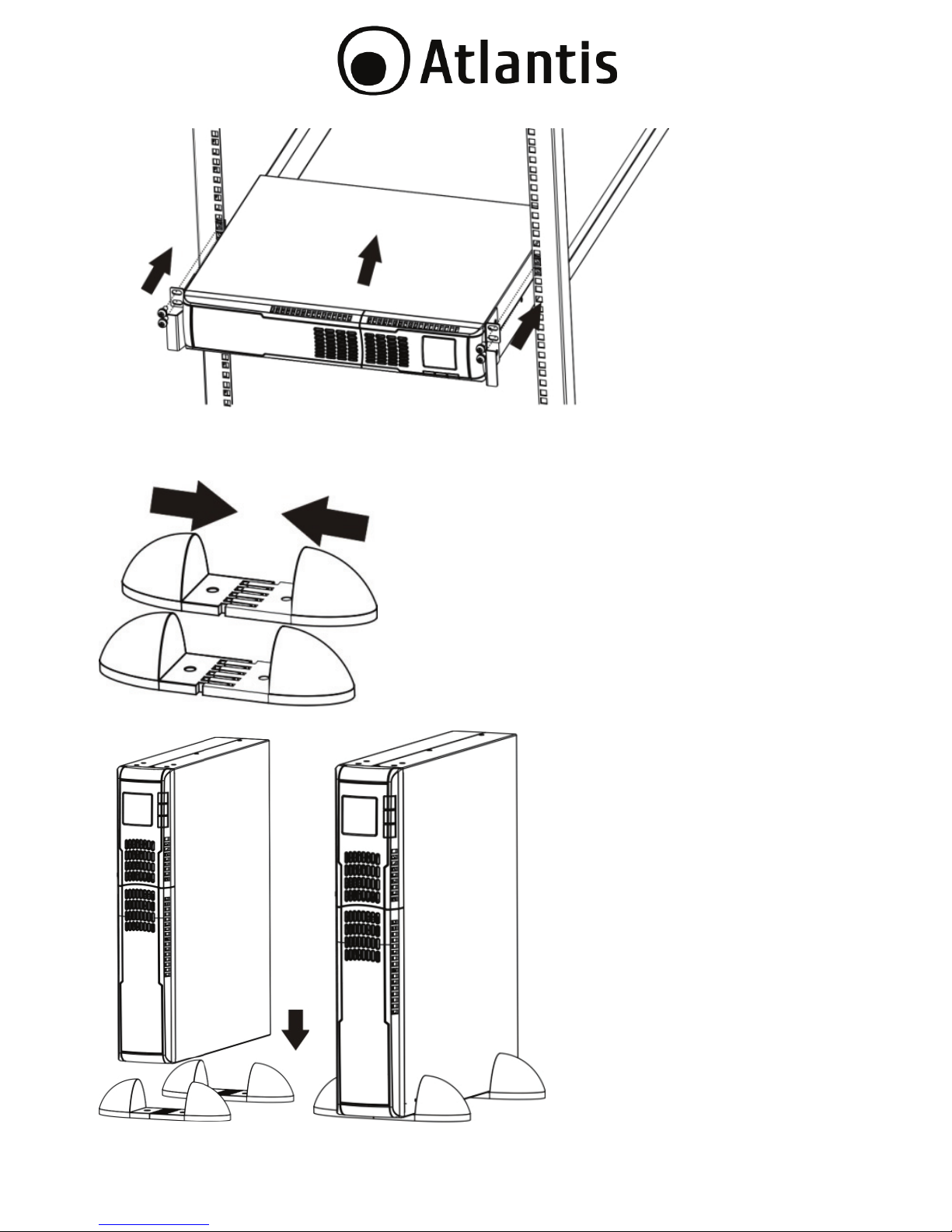
Rack-mount Installation
Step 1
Step 2
Page 52
52
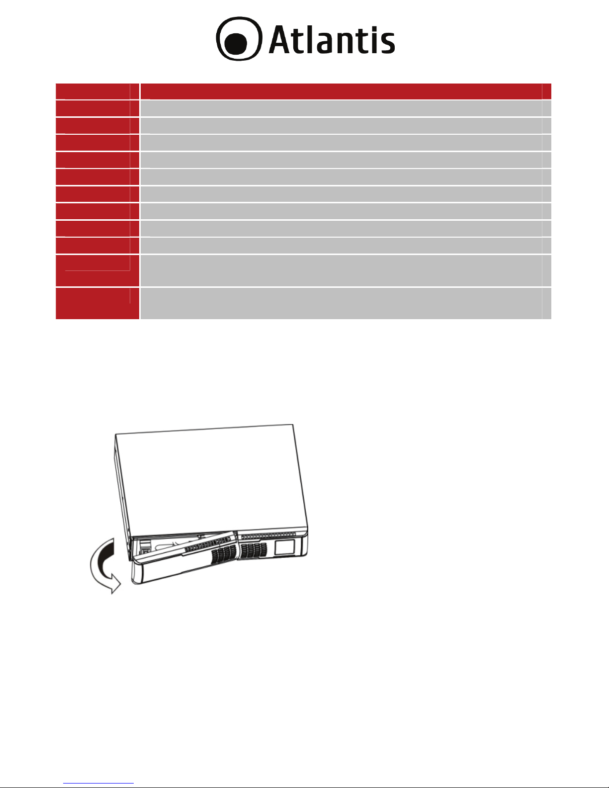
Tower Installation
Step 1
Step 2
Page 53

53
2.3 Setup The UPS
Step 1: UPS input connection
Plug the UPS into a two-pole, three-wire, grounded receptacle only. Avoid using
extension cords.
Step 2: UPS output connection
There two kinds of outputs: programmable outlets and general outlets. Please
connect non-critical devices to the programmable outlets and critical devices to the
general outlets. During power failure, you may extend the backup time to critical
devices by setting shorter backup time for non-critical devices.
Step 3: Communication connection
Communication ports:
USB Port
RS232 Port
Intelligent Slot
To allow for unattended UPS shutdown/start-up and status monitoring, connect the
communication cable one end to the USB/RS-232 port and the other to the
communication port of your PC. With the monitoring software installed, you can
schedule UPS shutdown/start-up and monitor UPS status through PC.
The UPS is equipped with intelligent slot perfect for either SNMP or AS400 card.
When installing either SNMP or AS400 card in the UPS, it will provide advanced
communication and monitoring options.
USB port and RS-232 port can’t work at the same time.
Page 54

54
Step 4: Network connection
Network/Fax/Phone surge port
Connect a single modem/phone/fax line into surge-protected “IN” outlet on the
back panel of the UPS unit. Connect from “OUT” outlet to the equipment with
another modem/fax/phone line cable.
Step 5: Disable and enable EPO function
Keep the pin 1 and pin 2 closed for UPS normal operation. To activate EPO function,
cut the wire between pin 1 and pin 2.
Page 55
55
Step 6: External battery connection (for A03-HP3551-RC models only)
Connect one end of external battery cable to UPS unit and the other end to battery
box. Use supplied battery detection wire in detection port of UPS unit and plug the
other end to battery bank. See below chart for detailed connection.
Maximum connected external battery boxes up to 4 units.
Step 7: Turn on the UPS
Press the ON/Mute button on the front panel for two seconds to power on the UPS.
The battery charges fully during the first five hours of
normal operation. Do not expect full battery run capability
during this initial charge period.
Step 8: Install software
For optimal computer system protection, install UPS monitoring software to fully
configure UPS shutdown. Please follow steps below to download and install
monitoring software:
Download and install software from www.atlantis-land.com
.
See software document for installation instruction.
When your computer restarts, the monitoring software will appear as an
orange plug icon ( ) located in the system tray, near the clock.
Page 56
56
3.0 UPS MANAGEMENT
3.1 Button Operation
Button Function
ON/MUTE
Button
Turn on the UPS: Press and hold ON/Mute button for at
least 2 seconds to turn on the UPS.
Mute the alarm: After the UPS is turned on in battery
mode, press and hold this button for at least 5 seconds to
disable or enable the alarm system. But it’s not applied to
the situations when warnings or errors occur.
Up key: Press this button to display previous selection in
UPS setting mode.
Switch to UPS self-test mode: Press and hold ON/Mute
button for 5 seconds to enter UPS self-testing while in AC
mode.
OFF/ENTER
Button
Turn off the UPS: Press and hold this button at least 2
seconds to turn off the UPS .
Confirm selection key: Press this button to confirm
selection in UPS setting mode.
SELECT
Button
Switch LCD message: Press this button to change the
LCD message for input voltage, input frequency, battery
voltage, output voltage and output frequency.
Setting mode: Press and hold this button for 10 seconds
to enter UPS setting mode when UPS is off.
Down key: Press this button to display next selection in
UPS setting mode.
Page 57

57
3.2 LCD Panel
Batter
y
Info
Load info
Input/output
and Battery
info
UPS status
Warnin
g
& Fault info/
Setting
operation
Backup
time info
Load info
UPS status
Backup time
info
Input/output
and Battery info
Warnin
g
& Fault I
Setting operation
Battery info
Page 58

58
Display Function
Backup time information
Indicates the backup time in pie chart.
Indicates the backup time in numbers.
H: hours, M: minute
Warning & Fault information
Indicates that the warning and fault occurs.
Indicates the warning and fault codes, and the codes are
listed in details in 3.8 section.
Setting Operation
Indicates the setting operation.
Input/Output & Battery information
Indicates the output/input voltage, output/input
frequency or battery voltage. V: voltage, Hz: frequency
Indicates the external battery pack numbers.
Load information
Indicates the load level by 0-25%, 26-50%, 51-75%, and
76-100%.
Indicates overload.
Indicates the load or the UPS output is short circuited.
UPS status
Indicates that programmable management outlets are
working.
Indicates that the UPS alarm is disabled.
Page 59
59
Indicates the UPS powers the output directly from the
mains.
Indicates the battery charger is working.
Indicates the UPS is working in boost mode
Indicates the UPS is working in buck mode
Battery information
Indicates the Battery level by 0-25%, 26-50%, 51-75%,
and 76-100%.
Indicates low battery.
Indicates there is something wrong with battery.
3.3 Audible Alarm
Battery Mode Sounding every 10 seconds.
Low Battery Sounding every second.
Overload Sounding twice every second.
Fault Continuously sounding.
Page 60

60
3.4 LCD Display Wordings Index
Abbreviation Display content Meaning
ENA Enable.
DIS Disable.
ESC Escape.
EP EPO.
FA Fan.
TP Temperature.
CH Charger.
RAC Rack display.
TOE Tower display.
SF Site Fault.
Page 61

61
3.5 UPS Setting
There are two parameters to set up the UPS.
Parameter 1: It’s for program alternatives. There are 4 programs to set up: output
voltage setting, , programmable outlets enable/disable, programmable outlets
setting , LCD display direction and exit.
01: Output voltage setting
Interface Settin
g
You may choose the following output voltage:
208: presents output voltage is 208Vac
220: presents output voltage is 220Vac
230: presents output voltage is 230Vac
240: presents output voltage is 240Vac
Parameters 1
Parameters 2
Page 62
62
02: Programmable outlets enable/disable
Interface Settin
g
ENA: Programmable outlets enable
DIS: Programmable outlets disable
03: Programmable outlets setting
Interface Settin
g
Setting the backup time limits in
minutes from 0-999 for programmable
outlets which connect to non-critical
devices on battery mode.
Page 63

63
04: LCD display direction setting
Interface Settin
g
RAC: the LCD display is horizontal.
TOE: the LCD display is vertical.
00: Exit setting
3.6 UPS Setting Steps for setting programmable outlet
Step LCD Settin
g
1 Before entering setting mode, the UPS
should be in Stand-by mode (offcharging) and make sure the battery is
connected. The LCD display is shown as
right.
Page 64
64
2 Press and hold the “Selec” button for
10 seconds to enter Setting mode.
3 Press the “Up“ button (ON/MUTE) to
switch to "02" of program list. Then
press “Enter“ button to enter value
setting of parameter 2. Press the “Up”
button to change the value to “ENA” to
enable the programmable outlet
function. Then press “Enter” button
again to confirm the setting.
4 Press the “Up“ button (ON/MUTE) again
to switch to "03" of program list. Then
press “Enter“ button for setting
programmable outlet time. Push “Up”
button to change the value of backup
time according your demand. Then
press “Enter” to confirm the setting.
5
Press“Up“ button (ON/MUTE) to switch
to "00" of program list. Then press
“Enter” button to exit setting menu.
6
Disconnect AC input and wait until the
LCD display is off. The new setting will
be activated when turning on the UPS
again.
Page 65

65
3.7 Operating Mode Description
Step LCD Description
ECO
mode
When the input voltage is within
voltage regulated range, UPS will power
the output directly from the mains. ECO
is an abbreviation of Efficiency
Corrective Optimizer. In this mode,
when battery is fully charged, the fan
will stop working for energy saving.
Buck
(AVR)
When the input voltage is higher than
the voltage regulation range but lower
than high loss point, the buck AVR will
be activated.
Boost
(AVR)
When the input voltage is lower than
the voltage regulation range but higher
than low loss point, the boost AVR will
be activated.
Battery When the input voltage is beyond the
acceptable range or power failure and
alarm is sounding every 10 seconds,
UPS will backup power from battery.
Page 66
66
Standby
Mode
UPS is powered off and no output
supply power, but still can charge
batteries.
3.8 Faults Reference Code
Fault event Fault code Icon
Bus start fail 01 x
Bus over 02 x
Bus under 03 x
Inverter soft start
fail
11 x
Inverter voltage
high
12 x
Inverter voltage
Low
13 x
Inverter output
short
14
Battery voltage
too high
27 x
Battery voltage
too low
28
Over temperature 41 x
Over load 43
Page 67
67
3.9 Warning Indicator
Warning Icon (flashing) Alarm
Low
Battery
Sounding every second
Overload Sounding twice every second
Battery
is not
connected
Sounding every second
Overcharge Sounding every second
Site wiring
fault
Sounding every second
EPO enable Sounding every second
Fan Failure Sounding every second
Over
temperature
Sounding every second
Charger
failure
Sounding every second
Battery Fault
Sounding every second
Page 68

68
APPENDIX A: TROUBLE SHOOTING & SUPPORT
If the UPS is not functioning properly, you can refer first to this chapter for simple
troubleshooting before contacting your reseller. This could save you time and effort
but if the problem persist, then consult your service provider.
A.1.1 UPS
The LED and the acoustic signals are a profit tool to individualize immediately
possible problems
Situation Check Items Solution
No indication and alarm
even though the mains is
normal.
1. The AC input power is not
connected well.
2. The AC input is connected
to the UPS output.
1. Check if input power
cord firmly connected
to the mains.
2. Plug AC input power
cord to AC input
correctly.
The icon and the
warning code
flashing on LCD display
and alarm is sounding
every second.
EPO function is activated. Set the circuit in close
position to disable EPO
function.
The icon and
flashing on LCD
display and alarm is
sounding every second.
Line and neutral conductors
of UPS input are reversed.
Rotate mains power
socket by 180° and then
connect to UPS system.
The icon and
flashing on
LCD display and alarm is
sounding every second.
T
he external or internal
battery is incorrectly
connected.
Check if all batteries are
connected well.
Page 69

69
Fault code is shown as
27 and the icon is
lighting on LCD display
and alarm is
continuously sounding.
Battery voltage is too high or
the charger is fault.
Contact Atlantis SpA.
Fault code is shown as
28 and the icon is
lighting on LCD display
and alarm is
continuously sounding.
Battery voltage is too low or
the charger is fault.
Contact Atlantis SpA.
The icon and the
icon are
flashing on LCD display
and alarm is sounding
twice every second.
UPS is overload Remove excess loads
from UPS output.
Fault code is shown as
43 and The icon
is
lighting on LCD display
and alarm is
continuously sounding.
T
he UPS shut down
automatically because of
overload at the UPS output.
Remove excess loads
from UPS output and
restart it.
Fault code is shown as
14 and alarm is
continuously sounding.
T
he UPS shut down
automatically because short
circuit occurs on the UPS
output.
Check output wiring and if
connected devices are in
short circuit status.
Page 70
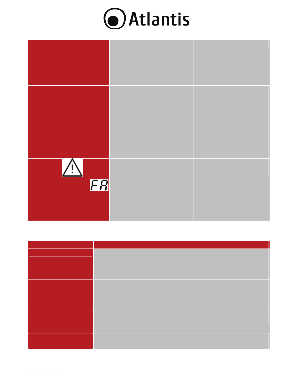
70
Fault code is shown as 1,
2, 3, 4, 11, 12, 13 and 41
on LCD display and
alarm is continuously
sounding.
A UPS internal fault has
occurred.
Contact Atlantis SpA.
Battery backup time is
shorter than nominal
value
1. Batteries are not fully
charged
2. Batteries defect
1. Charge the batteries
for at least 5 hours and
then check capacity. If
the problem still
persists, consult
Atlantis.
2. Contact Atlantis to
replace the battery.
The icon and the
warning code
flashing on LCD display
and alarm is sounding
every second.
Fan is locked or not workin
g
Check fans and notify
Atlantis!!
A.1.2 Battery and Fuse
Situation Solution
Backup time
T
he battery backup time (sometime called battery reserve
time or battery autonomy) is the length of time the battery
will supply power to the load during a power failure. You can
check on the Appendix Backup Time.
Wich type of
battery does UPS
use?
2 x 12VDC- 7A/h nell’A03-HP1101-RC
2 x 12VDC- 9A/h nell’A03-HP1501-RC
4 x 12VDC- 7A/h nell’A03-HP2001-RC
6 x 12VDC- 7A/h nell’A03-HP3351-RC
How often do I
have to change
battery?
Atlantis recommends to replace the batteries after 12-18
months.
Where can I find
batteries?
1. please contact Your reseller.
2. please contact directly Atlantis.
Page 71

71
A.1.3 ViewPower
Situation Solution
How to install the
Software.
Once started the UPS you can connect it to PC through USB
cable. At this time the SO detects and installs automatically all
drivers. Now you can install ViewPower on the PC.
PC doesn’t find the
UPS.
1. Check if the cable is properly connected
2. Use the original cable
3. Verify Your IP and please change if You are using
192.168.5.x subnet.
A.1.4 Opeartion/Storage
The UPS system contains no user-serviceable parts. If the battery service life (3~5
years at 25°C ambient temperature) has been exceeded, the batteries must be
replaced. In this case, please contact your dealer.
Be sure to deliver the spent
battery to a recycling facility
or ship it to your dealer in
the replacement battery
packing material.
Storage
Before storing, charge the UPS 5 hours. Store the UPS covered and upright in a
cool, dry location. During storage, recharge the battery in accordance with the
following table:
Storage Temperature Recharge Frequency Charging Duration
-25°C - 40°C Every 3 months 1-2 hours
40°C - 45°C Every 2 months 1-2 hours
Page 72

72
A.1.5 Support
For technical questions and support, please contact our help-desk by ticket on
http://www.atlantis-land.com/ita/supporto.php.
For generic informations, please send an e-mail to info@atlantis-land.com
.
For presales informations, please send an e-mail to prevendite@atlantis-land.com
.
Atlantis SpA
Via S. Antonio, 8/10
20020 Lainate (MI)
Fax: +39.02.78.62.64.39
Website: http://www.atlantis-land.com
Email: info@atlantis-land.com
Page 73

73
APPENDIX B: Battery Replacement
T
his UPS is equipped with internal batteries and user can
replace the batteries without shutting down the UPS or
connected loads.(hot-swappable battery design)
Replacement is a safe procedure, isolated from electrical
hazards.
Consider all warnings, cautions, and notes before replacing
batteries.
Upon battery disconnection, equipment is not protected
from power outages.
Battery Replacement
Step 1 (Remove Front Panel).
Step 2 (Disconnect battery wires).
Page 74

74
Step 3 (Pull out the battery box by removing two screws on the front panel).
Step 4 (Remove the top cover of battery box and replace the inside batteries).
Step 5 (After replacing the batteries, put the battery box back to original
location and screw it tightly).
Page 75
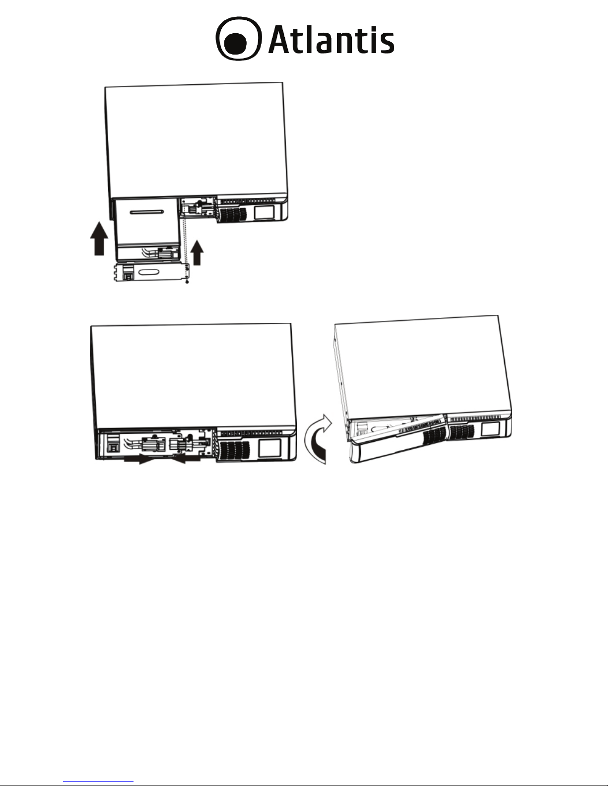
75
Step 6 (Connect the AC input and re-connect battery wires and Put the front
panel back to the unit).
Page 76

76
Battery Kit Assembly (option)
Please assemble battery kit first before installin
g
it inside of
UPS. Please select correct battery kit procedure below to
assemble it.
The Following Precautions Should be Observed When
Working on Batteries:
Remove watches, rings, or other metal objects.
Use tools with insulated handles.
Wear rubber gloves and boots.
Do not lay tools or metal parts on top of batteries.
Disconnect charging source prior to connecting or
disconnecting battery terminals.
2-Battery kit/ 4-Battery Kit /6-Battery Kit
Step 1 (Remove adhesive tapes).
Step 2 (Connect all battery terminals by following below chart).
Step 3 (Put assembled battery packs on one side of plastic shells).
Step 4 (Cover the other side of plastic shell as below chart. Then, battery kit is
assembly well).
Page 77

77
Page 78
78
Technical Features
Model
A
03-HP1101-RC
A
03-HP1501-RC
Power Rating(VA) 1100 1500
Power Rating(W) 640 880
INPUT
V
oltage:
162-290V
Frequency:
50Hz±5%
OUTPUT
V
oltage:
220V(±13%) [AC] / 220V(±3%) [INV]
Frequency:
50Hz (±1%)
A
VR Built-in
Waveform Pure SineWave (<8 % Linear Load@100%)
Pure SineWave (<15 % Non Linear Load@100%)
TRANSFER Line/Batter
y
Less than 2-6 ms (typical), max 10ms
EFFICIENCY AC Mode=97%
AVR=90%
Battery=83%
BATTERY
V
oltage 24VDC
Capacit
y
12V/7.0Ah 12V/9.0Ah
Q
uantit
y
2
Recharge Time 4 hours to (90%)
Type Sealed Maintenance Free Lead Acid VRLA Type
Design hot-swappable battery design
INDICATORS(Display LCD) Utility Normal, Backup, Battery Low and Battery
Fault conditions
PROTECTION Overload AC (>110%): Buzzer every 2 seconds
alarms & shuts down
Overload Inverter (>100%): UPS shuts down
after 10 seconds
Short Circuit INV: Electric Circuit
Short Circuit AC: ICS&Electric Circuit
Battery Over-drain Two stages: Controlled
Battery Low Warning & Cut Off
Modem/Network RJ45 / RJ11
Spike Suppression Meets EN61000-4-5
Noise Suppression Meets EN50991-1
Page 79

79
CONNECTIONS Output 8 xIEC 320 (Battery Power Supplied)
4 xIEC 320 (Programmable)
Computer USB/RS232 (USB port and RS-232 port
can’t work at the same time)
SNMP Slot
Backup Time 10 to 30 mins for typical PC Load
MECHANICAL Dimensions
(WxHxD):
380 x 438 x 88 (2U) mm
Net
Weight(with
Battery):
12,9 Kg 14,3 Kg
ENVIRONMENTS
Temp
erature 0°-40° C
Humidity 0-90% (non-condensing)
Noise Level Less then 45 dB
Package Contents Host Power RC Line Interactive SineWave
UPS
USB cable, Schuko Cable
Rack Kit
Tower Kit
Manual (Eng, Ita)
WEEE Instructions & Warranty
CERTIFICATION CE (EMC, Safety)
Page 80

80
Model
A
03-HP2001-RC
A
03-HP3351-RC
Power Rating(VA) 2000 3350
Power Rating(W) 1200 2000
INPUT
V
oltage:
162-290V
Frequency:
50Hz±5%
OUTPUT
V
oltage:
220V(±13%) [AC] / 220V(±3%) [INV]
Frequency:
50Hz (±1%)
A
VR Built-in
Waveform Pure SineWave (<8 % Linear Load@100%)
Pure SineWave (<15 % Non Linear Load@100%)
TRANSFER Line/Batter
y
Less than 2-6 ms (typical), max 10ms
EFFICIENCY AC Mode=97%
AVR=90%
Battery=85%
AC Mode=97%
AVR=90%
Battery=87%
BATTERY
V
oltage 48VDC 72VDC
Capacit
y
12V/7.0Ah 12V/7.0Ah
Q
uantit
y
4 6
Recharge Time 4 hours to (90%)
Type Sealed Maintenance Free Lead Acid VRLA Type
Design hot-swappable battery design
INDICATORS(Display LCD) Utility Normal, Backup, Battery Low and Battery
Fault conditions
PROTECTION Overload AC (>110%): Buzzer every 2 seconds
alarms & shuts down
Overload Inverter (>100%): UPS shuts down
after 10 seconds
Short Circuit INV: Electric Circuit
Short Circuit AC: ICS & Electric Circuit
Battery Over-drain Two stages: Controlled
Battery Low Warning & Cut Off
Modem/Network RJ45 / RJ11
Spike Suppression Meets EN61000-4-5
Noise Suppression Meets EN50991-1
CONNECTIONS Output 8 xIEC 320
(Battery Power
Supplied)
Output 7* xIEC 320
(Battery Power
Supplied)
Page 81
81
4 xIEC 320
(Programmable)
4 xIEC 320
(Programmable)*
Computer USB/RS232 (USB port and RS-232 port
can’t work at the same time)
SNMP Slot
Backup Time 10 to 30 mins for typical PC Load
MECHANICAL Dimensions
(WxHxD):
480 x 438 x 88 (2U)
mm
600 x 438 x 88 (2U)
mm
Net
Weight(with
Battery):
21 Kg 31 Kg
ENVIRONMENTS
Temp
erature 0°-40° C
Humidity 0-90% (non-condensing)
Noise Level Less then 45 dB
Package Contents Host Power RC Line Interactive SineWave
UPS
USB cable, Schuko Cable
Rack Kit
Tower Kit
Manual (Eng, Ita)
WEEE Instructions & Warranty
CERTIFICATION CE (EMC, Safety)
*6xIEC320 (connector C13, Inlet C14) & 1x IEC320 (connector C19, Inlet C20)
Page 82

82
Backup TIME & Battery
Code
A
03-HP3351-RC
43 24 18 9 6 3 2Min
A
03-HP2001-RC
31 17 13 5 2,5 Min
A
03-HP1501-RC
18 9 5 1,5 Min
A
03-HP1001-RC
13 4 2,5 min
Power Rating (W)
330 480 640 880 1200 1500 2000
A
03-HP2001-RC
Battery Low 44.4V±2VDC
Battery CutOFF 40.0V ± 2VDC
Battery Charging Volta
ge
55.2V ± 1.6VD
C A
03-HP33511-RC
Battery Low 66.6V±2VDC
Battery CutOFF 60.0V ± 2VDC
Battery Charging Volta
ge
82.8V ± 2.4VD
C
A
03-HP1001-RC/1501-RC
Battery Low 22.2V±1VD
C
Battery CutOFF 20.0V ± 1VD
C
Battery Charging Voltage 27.6V ± 0.8VD
C
Page 83

83
AVR
V
in(V)
AVRV
out(V) Not
e
Vin≦ 165V N/A Inv (220± 7%)
the UPS returns to AC
output mode when AC
input increase to 176V
166VأVinأ200V
Increase (15%) 206-250V Vout(min)=206V
201VأVinأ239V
N/A Vin
240VأVinأ274V Decrease (15%) 204-233V Vout(max)=233V
Vin ≧275V N/A Inv (220± 7%)
T
he UPS returns to AC
output mode when AC
input drops to 264V
Page 84

Atlantis SpA
Via S. Antonio, 8/10
20020 Lainate (MI)
info@atlantis-land.com
www.atlantis-land.com
 Loading...