

Page 1
Model :
Name of Purchaser :
Date of Purchase :
Serial No. of Unit :
Name and Address of the Seller :
Seller’s Stamp & Signature :
WATER DISPENSER
OWNER MANUAL
BOTTLED
AK SYSTEM ENGINEERS PVT LTD
B-32, Sector -5, Noida-201301
Uttar Pradesh (INDIA)
Model :
Name of Purchaser :
Date of Purchase :
Serial No. of Unit :
Name and Address of the Seller :
Seller’s Stamp & Signature :
WATER
DISPENSER
JUMBO
PlusPlus
BIG
PlusPlus
Plus
COOLING HEATING
HOT
Plus
COOLING HEATING
HOT
CAUTION :
Do not turn on
the red switch
until water flows
from the red tap
Heating Hot Cooling
PRIME
HEATING HOT COOLING
PRIME
AK SYSTEM ENGINEERS PVT LTD
B-32, Sector -5, Noida-201301
Uttar Pradesh (INDIA)
CAUTION:
Before using the water dispenser, read this manual and follow all safety rules and
operating instructions.
Page 2
INDEX
First published in April 2017
WATER DISPENSER
Website: www.atlantisplus.com
S.NO.
01
02
03
04
05
06
07
08
09
10
11
12
13
14
15
16
17
18
19
20
21
22
23
24
25
26
27
28
29
30
31
32
33
34
35
36
37
TOPIC
Important safeguards
Operating instructions
Installing the water bottle
Important notice about leaking bottles
Adjusting the temperature (cold water only)
Cleaning and maintenance
LED function indicators
Exploded view of machine - Atlantis Big Plus
Parts name - Atlantis Big Plus
Atlantis Big PlusTechnical specications Exploded view of machine - Atlantis Jumbo Plus
Parts name Atlantis Jumbo Plus Technical specications - Atlantis Jumbo Plus
Exploded view of machine - Atlantis Super
Parts name Atlantis Super Technical specications - Atlantis Super
Exploded view of machine - Atlantis Frosty
Parts name Atlantis Frosty Technical specications - Frosty Atlantis
Exploded view of machine - Atlantis Blue
Parts name Atlantis Blue Technical specications - Atlantis Blue
Exploded view of machine - Atlantis Xtra
Parts name Atlantis Atlantis Xtra Technical specications - Atlantis Atlantis Xtra
Exploded view of machine - Atlantis Prime
Parts name Atlantis Prime Technical specications - Atlantis Prime
Exploded view of machine - Atlantis Water Cooler
Parts name Atlantis Water Cooler Technical specications - Atlantis Water Cooler
Troubleshooting tips
Disposal of Machine
Frequently asked questions
Warranty conditions
Warranty instructions for user
Customer details
PAGE NO.
04
05
05
06
07
08
09
10
11
11
12
13
13
14
15
15
16
17
17
18
19
19
20
21
21
22
23
23
24
25
25
26
26
27
28
28
29
2 3
Page 3
Please read the enclosed operating instructions carefully and retain this
booklet for future reference.
We have carefully engineered your Bottled Water Dispenser to give you
years of service and trouble free operation.
IMPORTANT SAFEGUARDS
Never turn the dispenser upside down or tilt more than 45
degrees. If unit has been resting on its side for an extended
period of time, place the water dispenser in the upright
position for approximately 12 hours before turning it on.
Do not switch on the hot water until water runs out from
the red tap
• For use with 10-25 liter water bottles and most water filtration
systems , (not included).
• Never use this dispenser with water that is unsafe to drink or is
from an unknown source.
• Never use any other liquid in the dispenser other than known
and microbiologically safe bottled water.
• Never allow children to dispense hot water without proper and
direct supervision.
• This water dispenser is equipped with a grounded power cord
plug for your safety. It must be plugged into a grounded outlet.
Do not use an extension cord with your water dispenser.
• Keep your water dispenser in a dry place away from direct sunlight.
• Never put anything flammable close to the dispenser.
• Leave a minimum of 2” (5 cm) space around the back and sides of the
dispenser for proper ventilation.
• Always install your water dispenser on a level floor. Wait for three
minutes before restarting machine after shutting down.
• Always unplug the water dispenser before servicing or cleaning.
• Regular cleaning of your water dispenser is required for your warranty.
Please follow cleanin g instructions outlined in this manual and clean
the dispenser every 4 months.
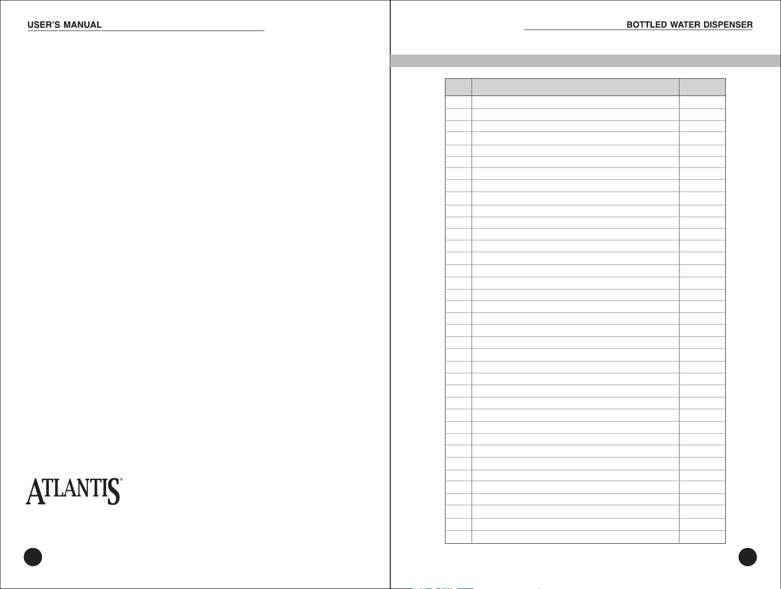
To avoid water overflow when cleaning
your dispenser, always remove the
bottle support funnel before pouring
water cleaning solution into the reservoir.
OPERATING INSTRUCTIONS
Initial Product Cleaning Procedure
As with most new appliances, it is recommended to
clean the reservoir prior to first time use.
1. Make sure the unit is unplugged and power switch is
turned off.
2. Remove the bottle support funnel, saturate a clean cloth with water
dispenser cleaner or vinegar and wipe the inside of the reservoir.
3. Pour water dispenser cleaner or a mixture of 0.3 gal / 1 L of vinegar
with 0.3 gal / 1 L of hot water into the reservoir and wait 20 minutes.
IMPORTANT: To avoid water overflow while cleaning the dispenser,
always remove the bottle support funnel before pouring water or
cleaning solution into the reservoir.
1. Press all dispensing buttons until water no longer comes out.
2. Drain the reservoirs from the drain valve on the back of the unit. (in hot &
cold unit only)
3. Rinse again with clean water.
4. Place bottle support funnel back on top of dispenser.
INSTALLING THE WATER BOTTLE
IMPORTANT: Always wash your hands first! Clean the top (neck) of the bottle
with a clean cloth and do not touch the part of the unit that the water touches.
Make sure the unit is unplugged and power switch is in the OFF position.
The water bottle can be purchased from your local retailer.
1. Remove the protective cap from the end of the water bottle unless the bottle
has a puncturable cap or sticker.
2. Lift and turn the bottle upside down, placing it securely on the bottle support
funnel
3. Press and hold all dispenser buttons until water flows from the dispenser.
Drain about 0.3 gal / 1 L of water before initial use. This does not need to be
repeated with replacement bottles.
4. Plug in the water dispenser.
5. Set the power switch at the rear of the dispenser to the ON position
6. Ready-to-dispense indicator lights will come on when water reaches
optimum temperatures and is ready for use.
.
4 5
Page 4
IMPORTANT NOTICE ABOUT LEAKING BOTTLES
If you find that your dispenser is leaking, check the water bottle first !
Almost all 10-25 liter water bottles are recycled, and handled extensively
during cleaning, filling, and shipping. As a result they are very prone to
developing pin holes or small cracks that can cause an overflow (or leak)
when placed on top of a water dispenser.
In almost all cases, there is nothing wrong with your water
dispenser. If you are experiencing a leak, this simple test
will allow you to determine whether your water bottle or
dispenser is the source of the problem.
1. Unplug the unit, turn off power switch and remove the water bottle.
2. a) Remove the bottle support funnel and check the
water level inside the reservoir – it should be at roughly
three-quarters full.
b) Please add or drain a few glasses of water to achieve
the required fill level. Water level should be
approximately 3/4” – 1” BELOW VENT TUBE
1.
2.a
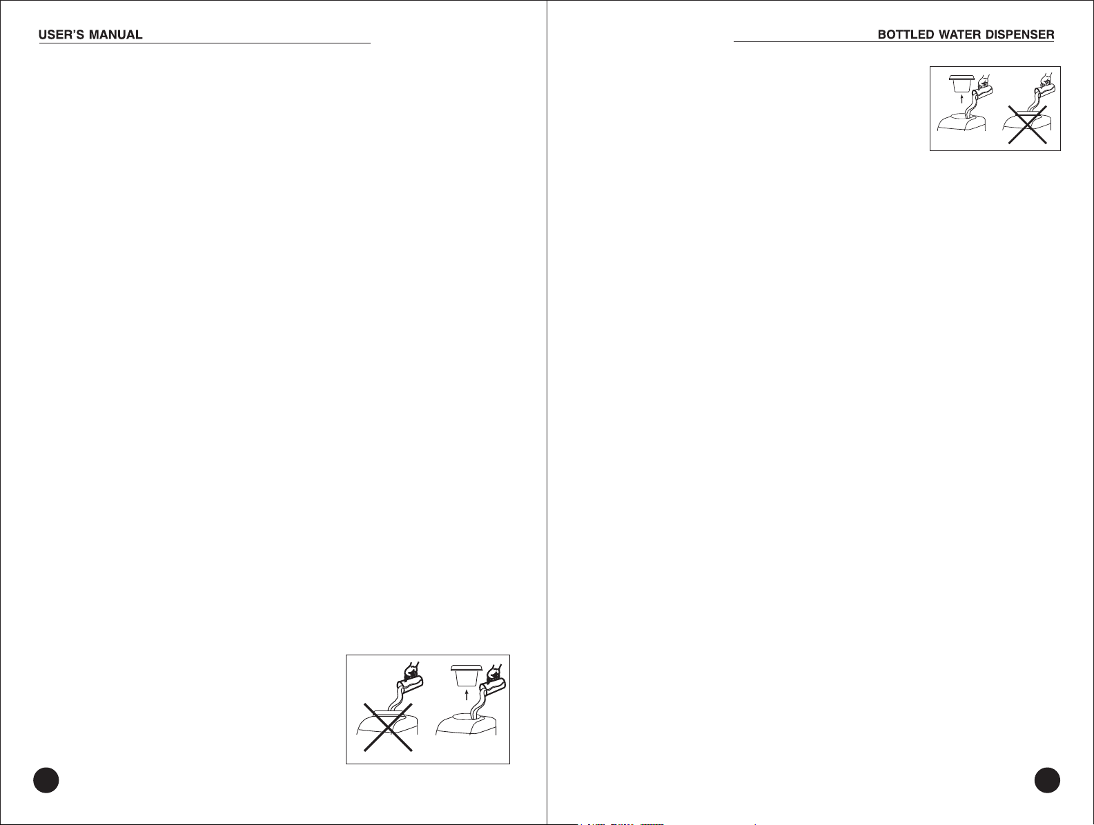
ADJUSTING THE TEMPERATURE (COLD WATER ONLY)
By turning the thermostat at the back of the unit, the
temperature can be adjusted. If the water dispenser is
not dispensing water, there could be a possible ice build
up due to the thermostat being set too cold. If this
happens, unplug the dispenser overnight and then reset
the thermostat. The thermostat knob is behind the OK
tested sticker at the back of the machine. Remove the
sticker and turn the knob clockwise to make the water
colder and anti clockwise to make it warmer.
Please note that the cold water thermostat has been factory adjusted to 11
Avoid adjusting the thermostat unless required.
CHILDPROOF SAFETY FEATURE - IN HOT & COLD MODEL ONLY
To prevent hot water from accidentally harming a child, the hot water
dispenser button has a safety switch on it. Available in some models only
DANGER: The hot water is heated to approximately 194˚ F / 90˚ C.
Temperatures above 125˚ F / 52˚ C can cause severe burns from scalding.
DO NOT ALLOW CHILDREN TO USE THE HOT WATER DISPENSING
BUTTON WITHOUT PROPER AND DIRECT SUPERVISION.
TESTED
R
E
M
R
A
W
OK
O
C.
3. Let the water sit for approximately 2 hours. If the
dispenser does not leak, it is the bottle that is leaking
due to a small crack or pinhole.
Please contact your water supplier for a replacement
bottle.
2.b
Vent Tube
Water Level
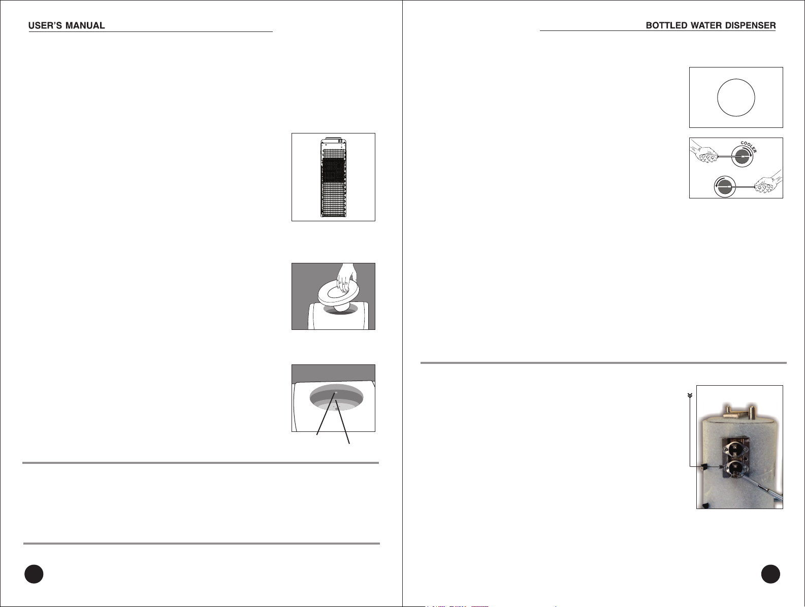
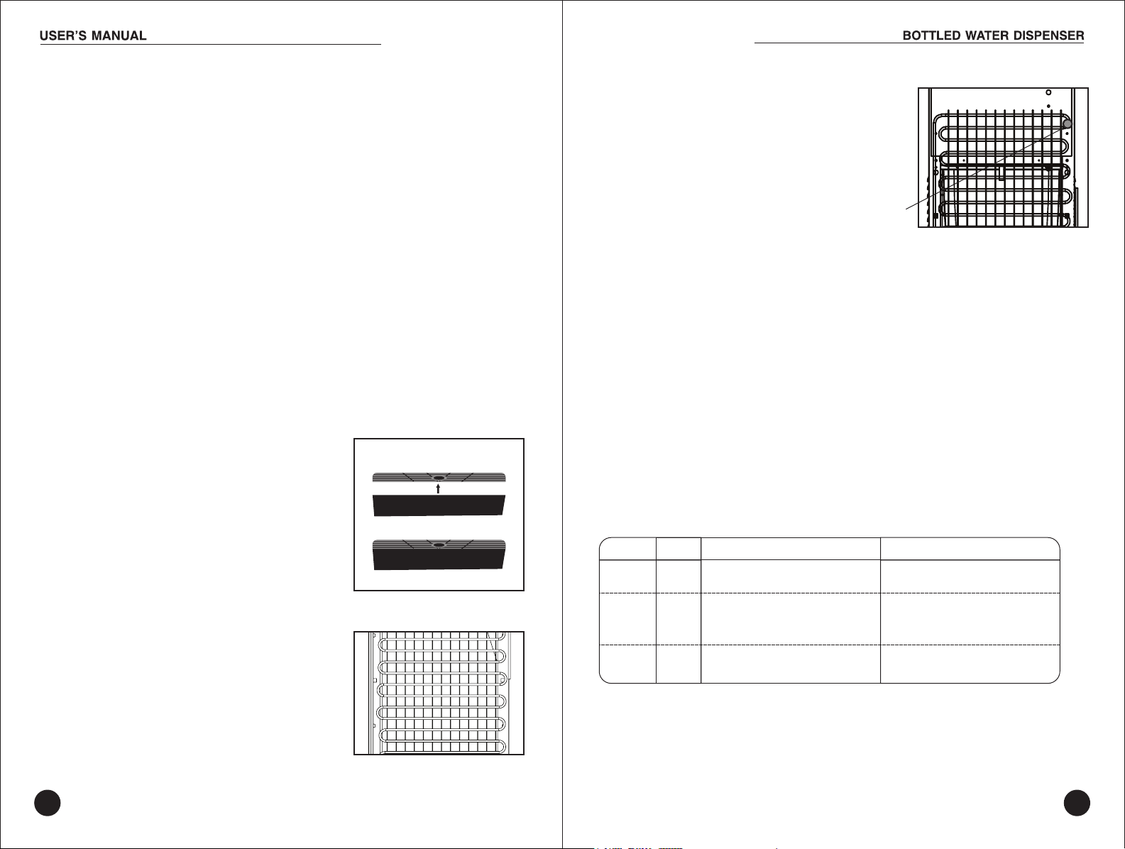
HOT WATER TEMPERATURE – IN HOT & COLD MODELS ONLY
The temperature of the hot water in the dispenser maintained
Reset Thermostat
by a preset automatic thermostat set at 85 °C and cannot be
adjusted manually by user.
There is also a manual reset safety thermostat set at 95 °C.
If there is no water in the hot tank and the hot water switch is
turned on by mistake, the manual safety button on the safety
DISPENSING WATER
1. Place a glass under the tap for water, press the lever until the desired
amount of water is dispensed.
2. Plain water temperature will be around 4 C to 6 C lower compared to
bottle water temperature.
o
o
thermostat will trip. In such an event, the reset button needs to
be preset as shown in picture (lower one on the tank) needs
to be pressed as shown in the picture.
ENSURE THAT THE DISPENSER IS POWERED OFF AND THERE IS WATER
IN THE HOT TANK BEFORE PRESSING THE RESET BUTTON ON
THE MANUAL SAFETY THERMOSTAT.
6 7
Page 5
CLEANING AND MAINTENANCE
Like most appliances, your new water dispenser requires periodic maintenance
to operate efficiently. Your water dispenser must be cleaned every 4 months.
Please note that as per your warranty, routine maintenance of the dispenser
is required. Failure to maintain the water dispenser will void your warranty.
DRAINING THE RESERVOIRS
Drain the reservoirs before and after cleaning,
when going on long vacations or if not using the
dispenser for long periods of time.
CLEANING YOUR WATER DISPENSER
IMPORTANT: Make sure you turn the power switch to the OFF position and
unplug the dispenser before performing any of the following cleaning
procedures.
CLEANING THE OUTSIDE OF THE WATER DISPENSER
The outside of the dispenser can be wiped clean with water dispenser
cleaning solution or a mild soap and water. Never use harsh chemicals or
abrasive cleaners. Rinse thoroughly with clean water and then dry surfaces.
CLEANING THE DRIP TRAY
To remove, take the grill off the tray and firmly lift the tray up, dislodging
it from the guides. Drain and clean.
The drip tray should be emptied and cleaned
regularly to remove spotting and any mineral
deposits. Clean with water dispenser cleaning
solution or a mild soap and water. For tough
deposits, add vinegar and let it soak until the
deposits come loose. Then wash, rinse and
dry thoroughly.
To replace, put the grill back on the tray and slide the tray onto the guides.
CLEANING THE CONDENSER
Vacuum or sweep away the dust from the
condenser coils at the back of the dispenser.
For best results, you can purchase a brush
designed specifically for this purpose from your
local appliance store. This will improve cooling
and efficiency.
Drain
valve
IMPORTANT!
Turn power switch to the OFF position and unplug the
dispenser before performing this procedure. Dispense hot water until
temperature drops to a safe level to avoidthe risk of scalding.
1. Remove the water bottle.
2. Press all dispensing buttons until water no longer comes out.
3. Place a bucket beneath the drain outlet on the back of the dispenser.
4. Remove the cap and plug from the drain valve (in hot & cold model only)
and let the water flow into the bucket.
Replace the cap and plug. A screwdriver or coin can be used to help loosen
the drain cap. Collect the water in a container, not the drip tray.
5. Replace the water bottle.
LED FUNCTION INDICATORS
LED
Yellow
Red
Blue/
Green
STATUS
“ON”
“ON”
is ready for dispensing
“ON”
For Hot & Cold model
Heater is in operation
The hot water has reached
its op t im u m temperature and
The cold water compressor
is in operation
is ready for dispensing
For Normal & Cold model
The cold water compressor is
in operation
The cold water has reached
its op t im u m temperature and
Power on
8 9
Page 6

EXPLODED VIEW OF MACHINE
PARTS IDENTIFICATIONS
MODEL - Atlantis Big Plus (M-30)
Description
S.No.
Puncturing Tube
01
Funnel
02
Top Cover
03
Tank Ring
04
Divider
05
Cold Thermostat
06
Main Lead
07
Switch Green- Cold
08
Switch Red- Hot
09
Handle
10
Filter
11
Back Plate Upper
12
Top Plate
13
Drain Set
14
Drain Pipe
15
Condenser
16
Side Panel Left/Right
17
Compressor
18
Condenser Rubber
19
Bottom Plate
20
No. of Faucets
Cold Storage Capacity
Power Source
Power Cold (Max.)
Power Hot
Refrigerant
Cooling Capacity
Heating Capacity
Condenser
Models available:
Floor Standing
Storage Cabinet
Cooling Cabinet
PARTS NAME
Qty.
1
1
1
1
1
1
1
1
1
2
1
1
1
1
1
1
2
1
4
1
TECHNICAL SPECIFICATIONS (BIG Plus)
3
8.0 Liters
220V/1P/50Hz
120 Watts
500 Watts
R 134 a (CFC Free)
5 Liters/hr
<_ 90 C, 5 Liters/hr
Static
Hot, Normal & Cold
Hot, Normal & Cold
Hot, Normal & Cold
RO Purifier Compatible
Description
S.No.
Plastic Feet
21
Compressor OLP
22
Compressor Relay
23
Front Lower
24
Drip Tray
25
Drip Tray Jali
26
Front Upper
27
28
Tap Blue - Cold
29
Tap White - Normal
30
Tap Red - Hot
31
Hot tank
32
Heating Thermostat 85 C Auto
33
Heating Thermostat 95 C Manual
34
Tap Connector
35
Front Upper Cover
36
LED PCB
37
Insulation Foam
38
Insulation Foam
39
Storage Tank
40
Steam Pipe
0
Qty.
4
1
1
1
1
1
1
1
1
1
0
0
1
1
1
3
1
1
1
1
1
1
10
Spe cificat ions sub ject to chang e withou t notice .
11
Page 7

EXPLODED VIEW OF MACHINE
PARTS NAME
PARTS IDENTIFICATIONS
MODEL- Atlantis Jumbo Plus (M-30)
Description
S.No.
Puncturing Tube
01
Funnel
02
Top Cover
03
Tank Ring
04
05
Divider
06
Cold Thermostat
07
Main Lead
08
Switch Green- Cold
09
Switch Red- Hot
10
Side Handle
11
Back Plate Upper
12
Top Plate
13
Drain Set
14
Drain Pipe
15
Fan Cooled Condenser
16
Back Plate Lower Jumbo
17
Motor
18
Condenser Plate
19
Side Panel Left/Right
20
Compressor
21
Bottom Plate
22
Condenser Rubber
No. of Faucets
Cold Storage Capacity
Power Source
Power Cold (Max.)
Power Hot
Refrigerant
Cooling Capacity
Heating Capacity
Condenser
Models available:
Floor Standing
Qty.
1
1
1
1
1
1
1
1
1
2
1
1
1
1
1
1
1
1
2
1
1
4
Description
S.No.
Plastic Feet
23
Compressor OLP
24
Compressor Relay
25
Front Lower
26
Motor Stand
27
Drip Tray
28
Drip Tray Jali
29
Front Upper
30
Tap Blue - Cold
31
Tap White - Normal
32
Tap Red - Hot
33
Hot tank
34
Heating Thermostat 85 C Auto
35
Heating Thermostat 95 C Manual
36
Tap Connector
37
Front Upper Cover
38
LED (PCB)
39
Insulation Foam
40
41
Insulation Foam
42
Storage Tank
43
Steam Pipe
o
o
TECHNICAL SPECIFICATIONS (JUMBO Plus)
3
8.0 Liters
220V/1P/50Hz
150 Watts
500 Watts
R 134 a (CFC Free)
10 Liters/hr
0
<_ 90 C, 5 Liters/hr
Fan Cooled
Hot, Normal & Cold
Qty.
4
1
1
1
1
1
1
1
1
1
1
1
1
1
3
1
1
1
1
1
1
Spe cificat ions sub ject to chang e withou t notice .
12 13
Page 8

EXPLODED VIEW OF MACHINE
PARTS NAME
Description
PARTS IDENTIFICATIONS
MODEL - Atlantis Super
01
02
03
38
37
36
35
34
33
32
31
30
29
28
27
26
25
04
05
06
07
08
09
10
11
12
13
14
15
16
17
18
S.No.
Funnel Cover
01
Funnel Close
02
Top Cover
03
Main Lead
04
Back Plate Upper
05
Sensor Tube
06
Switch Green- Cold
07
Switch Red- Hot
08
Switch Red- RO
09
Cold Thermostat
10
Top Plate
11
Cold Drain Pipe
12
Hot Drain Pipe
13
Hot Tank
14
Back Plate Lower
15
RO. Plate
16
Compressor
17
Side Panel Left/Right
18
Fan Cooled Condenser
19
TECHNICAL SPECIFICATIONS (SUPER)
No. of Faucets
Water Storage Capacity
Power Source
Power Cold (Max.)
Power Hot
Refrigerant
Cooling Capacity
Heating Capacity
Qty.
1
1
1
1
1
1
1
1
1
1
1
1
1
1
1
1
1
2
1
Condenser
Models available:
Floor Standing
Description
S.No.
20
Motor Stand
21
Motor
22
Leg
23
Heating Thermostat 95 C Manual
24
Heating Thermostat 85 C Auto
25
Front Lower
26
Front Upper
27
Drip Tray
28
Drip Tray Jali
29
Tap Blue- Cold
30
Tap Red - Hot
31
Tap White - Normal
32
LED
33
Display
34
Tap Connector
35
Tap Connector Strip
36
Storage Tank
37
Storage Tank Cover
38
SS Coil
3
17 Liters
220V/1P/50Hz
150 Watts
500 Watts
R 134 a (CFC Free)
10 Liters/hr
0
<_ 90 C, 5 Liters/hr
Fan Cooled
Hot, Normal & Cold
RO Purifier Compatible
Qty.
1
1
o
o
4
1
1
1
1
1
1
1
1
1
1
1
1
3
1
1
1
1
14
23
24
22
20 19
21
Spe cificat ions sub ject to chang e withou t notice .
15
Page 9

EXPLODED VIEW OF MACHINE
PARTS IDENTIFICATIONS
MODEL - Atlantis Frosty
01
02
03
35
34
33
32
31
30
29
28
27
26
25
24
23
22
21
04
05
06
07
08
09
10
11
12
13
14
15
16
Description
S.No.
Puncturing Tube
01
Funnel
02
Top Cover
03
Divider
04
Cold Thermostat
05
Main Lead
06
Switch Green- Cold
07
Switch Red- Hot
08
Handle
09
Back Plate Upper
10
Top Plate
11
Drain Set
12
Drain Pipe
13
Condenser
14
Side Panel Left/Right
15
Compressor
16
Bottom Plate
17
Plastic Feet
18
No. of Faucets
Cold Storage Capacity
Power Source
Power Cold (Max.)
Power Hot
Refrigerant
Cooling Capacity
Heating Capacity
Condenser
TECHNICAL SPECIFICATIONS (FROSTY)
PARTS NAME
Qty.
1
1
1
1
1
1
1
1
2
1
1
1
1
1
2
1
1
4
2
3.5 Liters
220V/1P/50Hz
120 Watts
500 Watts
R 134 a (CFC Free)
5 Liters/hr
<_ 90 C, 5 Liters/hr
Static
Description
S.No.
19
Compressor Relay
20
Compressor OLP
21
Front Lower
22
Front Upper
23
Drip Tray
24
Drip Tray Jali
25
Tap Blue - Cold
26
Tap Red - Hot
27
Hot tank
28
Heating Thermostat 85 C Auto
29
Heating Thermostat 95 C Manual
30
LED PCB
31
Thermocol Base Cold Tank
32
Thermocol Round Cold Tank
33
Tap Connector
34
Steam Pipe
35
Storage Tank
0
Qty.
1
1
1
1
1
1
1
1
o
o
1
1
1
1
1
1
2
1
1
Models available:
17
Floor Standing
Hot & Cold \ Normal & Cold
20
19 18
Spe cificat ions sub ject to chang e withou t notice .
16 17
Page 10

EXPLODED VIEW OF MACHINE
PARTS NAME
PARTS IDENTIFICATIONS
MODEL - Atlantis Blue (M-24)
Description
S.No.
Puncturing Tube
01
Funnel
02
Switch Red - Hot
03
Switch Green - Cold
04
Top Cover
05
06
Filter
07
Condenser
08
Cold Thermostate
09
Back Plate
10
Main Lead
11
Top Plate
12
Hot Tank
13
Heating Thermostate 95 c Auto
14
Heating Thermostate 85 c Manual
15
Drain Set
16
Condenser Rubber
17
Compressor
18
Relay OLP
TECHNICAL SPECIFICATIONS (BLUE)
No. of Faucets
Cold Storage Capacity
Power Source
Power Cold (Max.)
Power Hot
Refrigerant
Cooling Capacity
Heating Capacity
Condenser
Models available:
Floor Standing
Storage Cabinet
Cooling Cabinet
Table Top
S.No.
Qty.
1
19
1
20
1
21
1
22
1
23
24
1
25
1
26
1
27
1
28
1
29
1
30
0
0
1
31
1
32
1
33
1
34
4
35
1
1
2
3.5 Liters
220V/1P/50Hz
110 Watts
500 Watts
R 134 a (CFC Free)
2.5 Liters/hr
0
<_ 90 C, 5 Liters/hr
Static
Hot & Cold / Normal & Cold
Hot & Cold / Normal & Cold
Hot & Cold / Normal & Cold
Hot & Cold / Normal & Cold
RO Purifier Compatible
Description
Relay
Side Panel Left/Right
Plastic Feet
Bottom Plate
Front Lower- Floor Standing
Drip Tray
Drip Tray Jali
Front Upper
Tap - Cold
Tap - Hot
LED PCB
Tap Connector
Tap Connector Strip 2 Type
Thermocol Base & Round
Side Handle
Storage Tank Cold
Divider
Qty.
1
1
1
1
1
1
1
1
1
1
1
2
1
1
2
1
1
Specifications subject to change without notice.
18 19
Page 11

EXPLODED VIEW OF MACHINE
Description
PARTS IDENTIFICATIONS
MODEL - Atlantis Xtra (M-26)
01
48
47
46
45
44
43
42
41
40
39
38
37
36
35
34
33
32
31
30
39
28
27
2526
23
24
02
03
04
05
06
07
08
09
10
11
12
13
14
15
16
17
18
19
20
21
22
S.No.
Puncturing Tube
01
Funnel
02
Switch Red - Hot
03
Switch Green - Cold
04
Condenser Rubber
05
Top Cover
06
Condenser
07
Filter
08
Cold Thermostat
09
Back plate
10
Main Lead
11
Top Plate
12
Hot Tank
13
Heating Thermostat 85 c Auto
14
Heating Thermostat 95 c Manual
15
Tee Pipe
16
Drain Set
17
Compressor, relay Cover, Rubber
Grommet, Grommet Sleeve, Relay Cover
18
Clip
Relay
19
Relay OLP
20
Side Panel Left/Right
21
Plastic Feet
22
Bottom Plate
23
No. of Faucets
Cold Storage Capacity
Power Source
Power Cold (Max.)
Power Hot
Refrigerant
Cooling Capacity
Heating Capacity
Condenser
Models available:
Floor Standing
Storage Cabinet
Cooling Cabinet
Table Top
PARTS NAME
Description
S.No.
Qty.
1
1
1
1
1
1
1
1
1
1
1
1
o
o
1
1
1
1
1
1
1
1
1
4
2
TECHNICAL SPECIFICATIONS (Xtra)
3
4.0 Liters
220V/1P/50Hz
110 Watts
500 Watts
R 134 a (CFC Free)
3 Liters/hr
0
<_ 90 C, 5 Liters/hr
Static
Hot, Normal & Cold
Hot, Normal & Cold
Hot, Normal & Cold
Hot, Normal & Cold
Cabinet Thermocol
24
Thermostat Cover
25
Tap Connector Straight
26
Door Hinge/Door Axle
27
Cabinet Bottom Tray
28
Cabinet Housing
29
Cabinet Middle Tray
30
Front Lower-Cooling Cabinet
31
Tap Connector Taper
32
Door Thermocol
33
Door Liner
34
Cooling Plate
35
Door gasket
36
Front Upper
37
Drip Tray
38
Drip Tray Jali
39
Tap White - Normal
40
Tap Red - Hot
41
Tap Blue - Cold
42
Tap Cover
43
LED PCB
44
Side Handle
45
Thermocol Base & Round
46
Storage Tank Cold
47
Divider
48
Qty.
1
1
1
1
1
1
1
1
2
1
1
1
1
1
1
1
1
1
1
1
1
1
1
1
1
RO Purifier Compatible
20
Spe cificat ions sub ject to chang e withou t notice .
21
Page 12

EXPLODED VIEW OF MACHINE
PARTS IDENTIFICATIONS
MODEL- Atlantis Prime
52
51
50
49
48
47
46
45
44
43
42
41
40
39
38
37
36
35
34
33
32
31
30
29
28
23
2526
27
24
1
2
3
4
5
6
7
8
9
10
11
12
13
14
15
16
17
18
19
20
21
22
Description
S.No.
Puncturing Tube
01
Funnel
02
Switch Red - Hot
03
Switch Green - Cold
04
Condenser Rubber
05
Top Cover
06
Condenser
07
Filter
08
Cold Thermostat
09
Back Plate
10
Main Lead
11
Top Plate
12
Hot Tank
13
Silicon Pipe tank Inlet U
Silicon Pipe Cold Water Outlet
14
Silicon Pipe Water Outlet
T Pipe
15
Drain Set
16
Compressor with Accessories
17
Relay 36 no.
18
Relay OLP 36 no.
19
Side Panel Left/Right
20
Rubber Feet
21
U Channel
22
Bottom Plate
23
Middle Plate
24
Cabinet Thermocol
25
No. of Faucets
Cold Storage Capacity
Power Source
Power Cold (Max.)
Power Hot
Refrigerant
Cooling Capacity
Heating Capacity
Condenser
Models available:
Floor Standing
Storage Cabinet
Cooling Cabinet
Table Top
TECHNICAL SPECIFICATIONS (PRIME)
PARTS NAME
S.No.
Qty.
1
26
1
27
1
28
1
29
1
30
1
31
1
32
1
33
1
34
1
35
1
36
1
37
1
38
39
1
40
41
1
42
43
1
44
45
1
46
1
47
4
48
1
49
1
50
1
51
1
52
3
3.5 Liters
220V/1P/50Hz
110 Watts
500 Watts
R 134 a (CFC Free)
3 Liters/hr
0
<_ 90 C, 5 Liters/hr
Static
Hot, Normal & Cold
Hot, Normal & Cold
Hot, Normal & Cold
Hot, Normal & Cold
Description
Thermostat Cover
Cabinet Strip Lower/Upper
Door Hinge/Door Axle
Cabinet Bottom Tray
Cabinet
Cabinet Middle Tray
Front Lower
Door Thermocol
Door Liner
Cooling Plate
Door Gasket
Drip Tray
Drip Tray Jali
Tap M28
Transparent Dispay
Front Upper
Child Lock
Pusher left
Pusher Middle
Pusher Right
LED PCB
Thermocol Base & Round
Heating Thermostat 90 c
Heating Thermostat 86 c Auto
Side Handle
Storage Tank
Divider
o
o
Qty.
1
1
1
1
1
1
1
1
1
1
1
1
1
3
1
1
1
3
1
1
1
1
1
1
2
1
1
22
Spe cificat ions sub ject to chang e withou t notice .
23
Page 13

EXPLODED VIEW OF MACHINE
PARTS NAME
PARTS IDENTIFICATIONS
MODEL - Atlantis Water Cooler
01
02
03
04
05
06
07
27
26
25
24
23
22
08
09
10
11
12
13
14
15
Description
S.No.
Puncturing Tube
01
Funnel
02
Storage Tank Plastic
03
Top Cover
04
Storage Tank
05
Back Plate Upper
06
Storage Tank Insulation
07
Thermostat
08
Main Lead
09
Tank Plate
10
Back Plate Lower
11
Condenser Fan Cool
12
Motor
13
Drain Set
14
TECHNICAL SPECIFICATIONS (WATER COOLER)
No. of Faucets
Cold Storage Capacity
Power Source
Power Cold (Max.)
Power Hot
Refrigerant
Cooling Capacity
Heating Capacity
Condenser
Qty.
1
1
1
1
1
1
1
1
1
2
1
1
1
Description
S.No.
15
Leg
16
Side Panel Left/Right
17
Bottom Plate
18
Motor Stand
19
Compressor
20
Compressor Relay
21
Compressor OLP
22
Front Panel Lower
23
Drip Tray
24
Tap Connector
25
Tap Cold
26
Tap Normal
27
Front Panel Upper
1
2
20 Liters
220V/1P/50Hz
150 Watts
NA
R 134 a (CFC Free)
10 Liters/hr
NA
Fan Cooled
Qty.
4
2
1
1
1
1
1
1
1
2
1
1
1
24
20 19 18
21
16
17
25
Page 14

TROUBLESHOOTING TIPS
Problem
Water dispenser
or dispensing tap
is leaking
Water is not hot or
cold enough
Hot water
Cold water
Water dispenser
is not dispensing
water
Water dispenser
is noisy
Possible Cause
Small pin hole or crack in the bottle,
(common with recycled water
bottles).
Drain cap and silicone seal are
not secure.
Water was poured directly into bottle
support funnel and overflowed.
All the water in the tank has been
used.
The unit is unplugged.
The circuit breaker in your home is
tripped or the fuse has blown.
Power switch not turned ON at
back of unit.
Temperature manual thermostat
tripped.
Thermostat needs to be adjusted
for colder water.
Empty water bottle.
Possible ice build up due to
thermostat set too cold.
Bottle making a gurgling noise as it
fills the tank.
Water dispenser is uneven.
Unplug overnight, then reset. Reduce
thermostat setting.
surface that can support its full weight.
minutes for the water to heat or cool.
Suggested Solution
Conduct water bottle leak test
as outlined in manual.
Ensure seal is secure in drain
plug an d tighten drain cap.
Drain by pressing dispenser buttons.
Replace with full bottle and wait 30
Plug it into the outlet.
Reset the breaker or replace the fuse.
Turn switch to the ON position.
Press the reset button on manual
thermostat. (as shown in the diagram
page 5)
Rotate knob using screwdriver
clockwise to increase cooling and
anti clockwise decrease cooling.
Replace with full bottle.
This is normal.
Make sure the dispenser is on an even
DISPOSAL OF MACHINE:
AercomplengthelifecycleWaterDispensersshouldbetreatedaspere-waste
managementrules.
Consumerorbulkconsumershouldchannelizee-wastegeneratedbythemto
authorizedcolleconcentreorregistereddismantlerorrecycler.
BulkConsumershouldmaintainrecordsofe-wastegeneratedbythem.
Consumershallensurethatewasteisnotbeingdroopedingarbagebin
containingwastedesnedfordisposal.
ATTENTION: Do not return this product to the store. For questions on
operation, assembly or parts, please contact us at authorised service centre.
FREQUENTLY ASKED QUESTIONS
Q . WHY IS MY WATER DISPENSER LEAKING?
A: If you are experiencing a leak with your water dispenser please do the
following to see if the water bottle or the dispenser is leaking.
1. Unplug the unit, turn off power switch and remove the bottle.
2. Remove the bottle support funnel and check the water level inside the
reservoir – it should be at roughly three-quarters full.
Water level should be approximately 3/4” – 1” BELOW VENT TUBE.
3. Let water sit for 2 hours. If the dispenser does not leak, it is the bottle
that is leaking due to a small crack or pinhole and it needs to be replaced.
If the dispenser is leaking, please contact authorized service centre.
Q.: WHY DO I GET A PLASTIC TASTE FROM MY DISPENSER?
A.: As with most new appliances such as coffee makers and kettles, there is
often a plastic taste upon initial start-up of the unit. To remove this taste,
simply follow the cleaning instructions outlined in Initial Product Cleaning
Procedure (pg.5)
Q.: WHAT DO THE READY-TO-DISPENSE INDICATOR LIGHTS MEAN?
A.: When illuminated, they mean the following:
LED
Yellow
Red
Blue/
Green
STATUS
“ON”
“ON”
For Hot & Cold model
Heater is in operation
The hot water has reached
its op t im u m temperature and
is ready for dispensing
The cold water compressor
“ON”
is in operation
is ready for dispensing
For Normal & Cold model
The cold water compressor is
in operation
The cold water has reached
its op t im u m temperature and
Power on
Q: WHAT IS THE SPIKE THAT GOES INTO THE BOTTLE?
A.: Water dispensers feature a “puncturing tube” as part of the bottle support
funnel, providing added convenience for water bottle installation. Depending
on the water bottle supplier, a small opening may or may not be present in the
bottle cap for this specific purpose. If the puncturing tab is not present, the
entire bottle cap must then be removed to eliminate possible damage to the
puncturing tube. If the opening is present, remove the protective seal prior to
installing the bottle.
26
27
Page 15

WARRANTY CARD
This product is covered under a one year warranty to be free from defects in
workmanship and material under normal use and service for a period of 12 months from
the date of purchase.
1. The guarantee extended herein is limited to the repair and/or replacement of defective
part’s, and the manufacturer would not be responsible for any consequential
liability/damage/loss arising due to such defects.
2. Warranty card duly filled in and stamped by the dealer, along with a copy of the invoice
should be produced for any warranty claims. All expenses incurred in sending and
collecting the unit or part thereof from the authorized service center will be payable by
the customer
his
3.T
warranty does not cover accessories such as mains cord, relay, funnel and plastic
parts.
4. The warranty is void if :
a) It is found that the unit has been subject to unauthorized installation or repair.
b) The voltage of the power supply is not within the specified limited (230 V 50Hz +10%)
c) Damage is caused during transit, due to accident, flood, fire, other natural hazards,
neglect or misuse.
5. Any liquid except water is used in the container.
6. The defective parts must be sent to the company, freight prepaid and insured, for the
company’s examination and satisfaction that they are defective. Return freight and
insurance on such repaired/replacement parts plus any excise duty and taxes/levies will
be extra.
7. Failure/deterioration of any part/assembly arising, in the company’s opinion by reasons
of shifting to another location, accident, alteration, abuse/misuse, substitution of original
part’s with unauthorized part’s or any damage caused by fire/flood etc, or exposure to
weather conditions, are not covered under this warranty.
_
Model No. :
Date of Purchase :
Customer Name & Address
Tel :
CUSTOMER DETAILS
Serial No.
Dealer Name & Address
Tel :
Customer’s Signature Dealer’s Signature & Stamp
8. This warranty will continue to be in force for the term herein specified irrespective of
any replacement parts which may be provided under warranty and such replacement
parts shall not carry any fresh warranty.
WARRANTY INSTRUCTIONS FOR USER
1. This warranty card has 2 parts. Kindly ensure that the Merchant fills both parts
correctly.
2. Part A is the customer’s copy. It should be retained by you for your record.
3. Part B must be torn and mailed to the company’s address (mentioned there itself.).
4. In the event of a defect developing in the product, contact the Merchant./ company
for obtaining warranty service by informing defect, model & serial no. and date of
purchase.
5. On receiving your complaint, trained technician will call on you promptly. In the
unlikely event of the technician deciding that the product requires attention at
customer care center, kindly arrange to deliver the machine to the customer care
center for further action.
292831
Page 16

30
 Loading...