

Page 1
NetCamera
IP Security Wireless Camera
A02-IPCAM-W54
MULTILANGUAGE
Company certified ISO 9001:2000
Quick Start Guide
A02-IPCAM-W54_GX01
Where solutions begin
Page 2

Page 3

ITALIANO
Questo prodotto è coperto da garanzia Atlantis Land
Fast-Swap della durata di 3 anni. Per maggiori dettagli in merito
o per accedere alla documentazione completa in Italiano fare
riferimento al sito www.atlantis-land.com.
ENGLISH
This product is covered by Atlantis Land 3 years Fast-Swap
warranty. For more detailed informations please refer to the web
site www.atlantis-land.com.
For more detailed instructions on configuring and using this
device, please refer to the online manual.
FRANCAIS
Ce produit est couvert par une garantie Atlantis Land
Fast-Swap 3 ans. Pour des informations plus détaillées,
référez-vous svp au site Web www.atlantis-land.com.
DEUTSCH
Dieses Produkt ist durch die Atlantis Land 3 Jahre Fast-Swap
Garantie gedeckt. Für weitere Informationen, beziehen Sie sich
bitte auf Web Site www.atlantis-land.com.
ESPAÑOL
Este producto està cubierto de garantía Atlantis Land
Fast-Swap por 3 años. Para una información más detallada, se
refiera por favor al Web site www.atlantis-land.com
.
Page 4
The award of the information is facultative, but its lack will
prevent ATLANTIS LAND® from starting the Guarantee process
requested.
r
a
a
y
o
u
r
p
r
o
d
u
c
t
!
c
u
u
o
o
c
o
c
m
t
t
m
m
!
!
y
o
u
r
p
r
o
n
n
y
n
t
o
t
t
u
r
i
s
-
l
i
s
-
l
i
s
-
d
p
r
o
d
a
n
d
.
a
n
n
d
d
c
.
c
.
a
l
R
e
g
i
s
t
e
R
e
g
R
e
w
w
w
w
w
w
g
w
w
w
Registration on the web site
r
i
s
t
e
r
i
s
t
e
.
a
t
l
a
.
a
t
l
.
a
t
l
www.atlantis-land.com within 15 days
from the purchase of the product dismiss
the customer from showing a valid proof of
purchase (Sale Receipt or Invoice) in case
of the request of intervention. For further
information we invite you to look at our web
site at the section WARRANTY.
Copyright
The Atlantis Land logo is a registered trademark of Atlantis Land
SpA. All other names mentioned mat be trademarks or
registered trademarks of their respective owners. Subject to
change without notice. No liability for technical errors and/or
omissions.
Page 5

MULTILANGUAGE Quick Start Guide
ITALIANO
1.1 Contenuto della confezione ............................... 7
1.2 I LED frontali......................................................... 7
1.3 Le porte posteriori................................................ 8
1.4 Cablaggio.............................................................. 9
1.5 Settaggi di Default ............................................. 11
1.6 Configurazione IP Security Cam ..................... 11
1.7 Java/ActiveX Mode............................................ 12
1.8 System Administration ...................................... 14
1.9 Supporto Offerto ................................................ 14
ENGLISH
1.1 Package contents .............................................. 16
1.2 The Front Panel LEDs ...................................... 16
1.3 The Rear Ports................................................... 17
1.4 Cabling ................................................................ 18
1.5 Default Settings.................................................. 19
1.6 Browser configuration ....................................... 20
1.7 Java/ActiveX Mode............................................ 20
1.8 System Administration ...................................... 22
1.9 Support................................................................ 22
FRANCAIS
1.1 Contenu de la boîte ........................................... 24
1.2 Face avant .......................................................... 24
1.3 Face arrière ........................................................ 25
1.4 Câblage ............................................................... 26
1.5 Configuration initiale.......................................... 27
1.6 Configuration avec le Browser......................... 28
1.7 Java/ActiveX Mode............................................ 28
1.8 System Administration ...................................... 30
1.15 Support.............................................................. 30
5
Page 6

ITALIANO
AVVERTENZE
Abbiamo fatto di tutto al fine di evitare che nel testo, nelle
immagini e nelle tabelle presenti in questo manuale, nel
software e nell'hardware fossero presenti degli errori.
Tuttavia, non possiamo garantire che non siano presenti
errori e/o omissioni. Infine, non possiamo essere ritenuti
responsabili per qualsiasi perdita, danno o incomprensione
compiuti direttamente o indirettamente, come risulta
dall'utilizzo del manuale, software e/o hardware.
Il contenuto di questo manuale è fornito esclusivamente per
uso informale, è soggetto a cambiamenti senza preavviso (a
tal fine si invita a consultare il sito www.atlantisland.it
www.atlantis-land.com
non deve essere interpretato come un impegno da parte di
Atlantis Land spa che non si assume responsabilità per
qualsiasi errore o inesattezza che possa apparire in questo
manuale. Nessuna parte di questa pubblicazione può essere
riprodotta o trasmessa in altra forma o con qualsiasi mezzo,
elettronicamente o meccanicamente, comprese fotocopie,
riproduzioni, o registrazioni in un sistema di salvataggio,
oppure tradotti in altra lingua e in altra forma senza un
espresso permesso scritto da parte di Atlantis Land spa.
Tutti i nomi di produttori e dei prodotti e qualsiasi marchio,
registrato o meno, menzionati in questo manuale sono usati
al solo scopo identificativo e rimangono proprietà esclusiva
dei loro rispettivi proprietari.
per reperirne gli aggiornamenti) e
o
6
Page 7
ITALIANO
Questo manuale è inteso come una guida rapida, pertanto
per ulteriori dettagli sulla configurazione fare riferimento al
manuale esteso presente sul CD. Consultare il sito Web
www.atlantis-land.com per reperire eventuali
aggiornamenti.
1.1 Contenuto della confezione
Atlantis Land NetCamera, CDRom contenente il manuale ed
il software IPView SE, Guida di Quick Start, cavo CAT-5
LAN, Antenna esterna, Alimentatore (5V, 2.5A) e Piedistallo
in metallo.
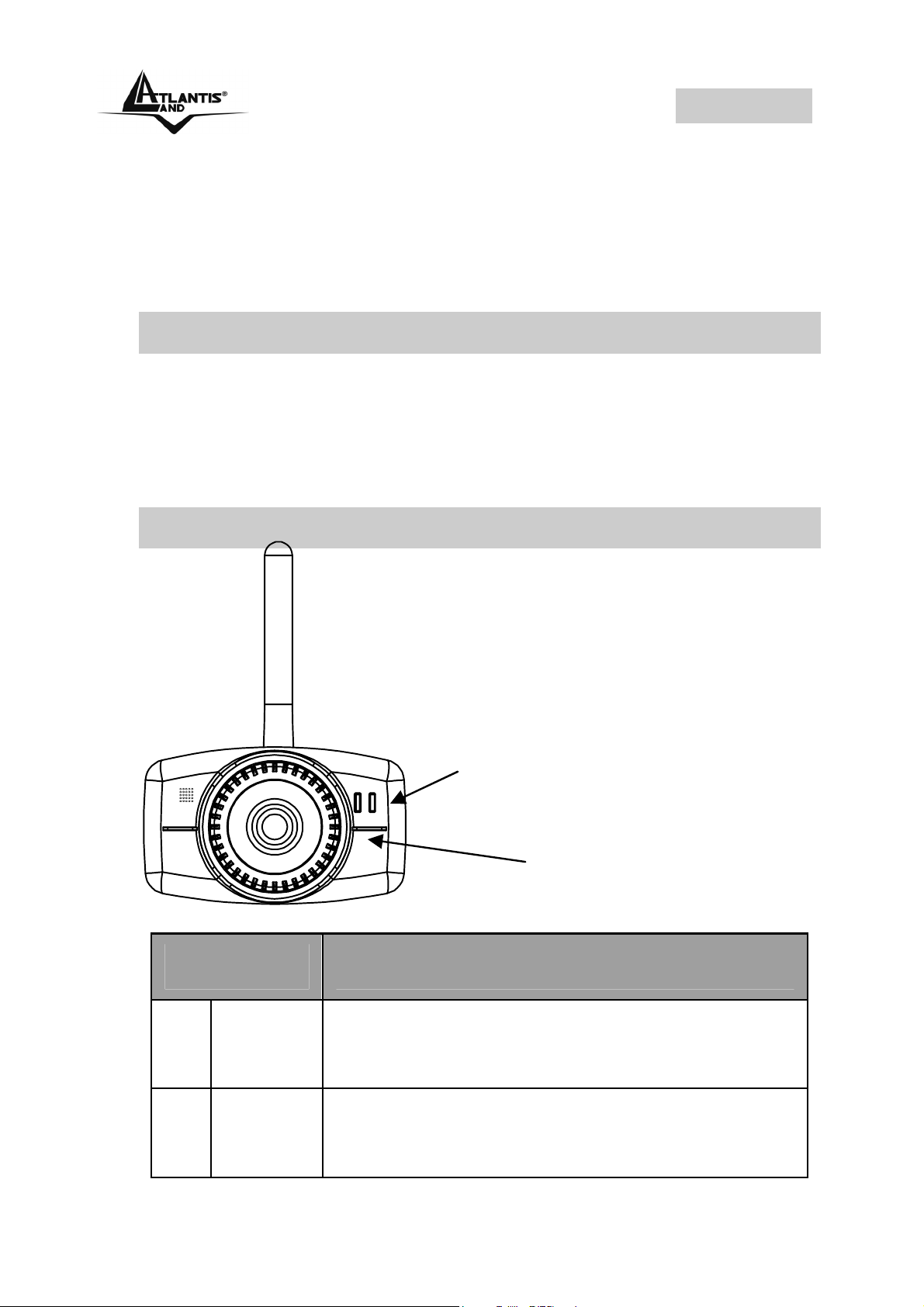
1.2 I LED frontali
LED Informazione
Acceso di blu indica il corretto
Link LED
Power LED
1 Power
2 Link
collegamento del dispositivo alla rete
elettrica
Arancio Fisso= connessione attiva
Lampeggiante quando vi è
trasmissione/ricezione
7
Page 8
ITALIANO
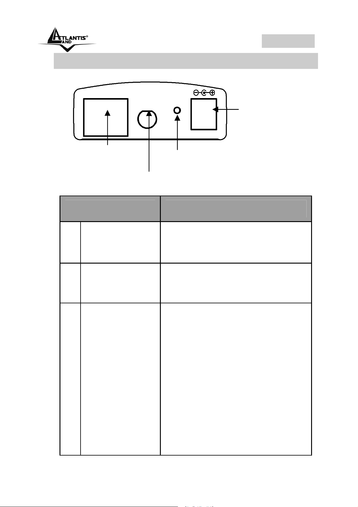
1.3 Le porte posteriori
10/100 Ethernet
Network
Cable
Porte Utilizzo
1 Network Cable
Antenna
Connector
DC Power
ANT
Connector
Reset
DC 5V
Reset Button
Connettere il cavo RJ-45 a
questa porta per effettuare
l’allacciamento alla Lan
2 Antenna
Connector
3 Reset
Avvitare l’antenna a questo
connettore
Dopo che il dispositivo è
acceso, premere per effettuare il
reset o il restore. Le operazioni
sono le seguenti:
1 secondi: per resettare il
dispositivo (il Led Pwr
comincerà a lampeggiare per
indicare l’avvenuto reset)
3 secondi: per riportare il
dispositivo alle condizioni iniziali
(premere sino a che il tasto
power comincerà a
lampeggiare)
8
Page 9
ITALIANO
4 POWER (jack)
Connettere l’alimentatore a
questo jack
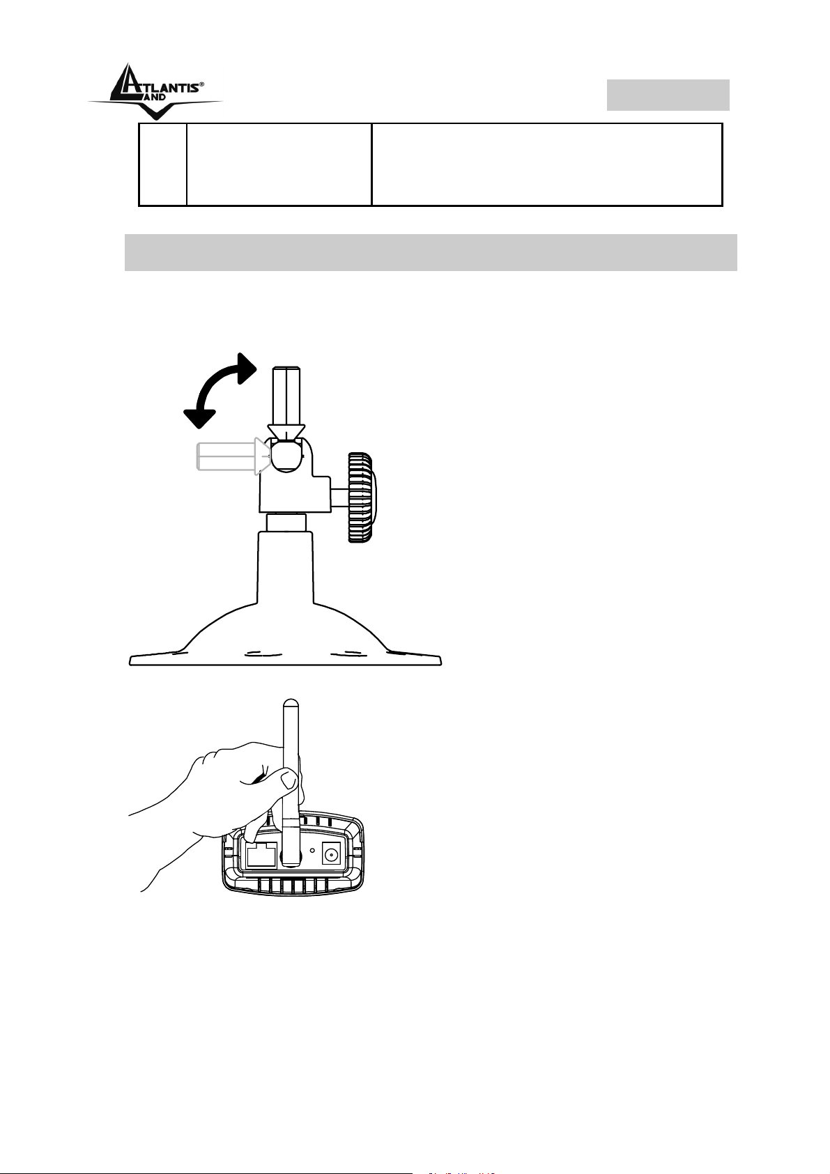
1.4 Cablaggio
Prendere il piedistallo dalla confezione e collegarlo ala
NetCamera. Sono presenti, nella base del supporto, 3 fori da
utilizzarsi per un fissaggio sulla parete.
Avvitare l’antenna sul connettore apposito, come da figura:
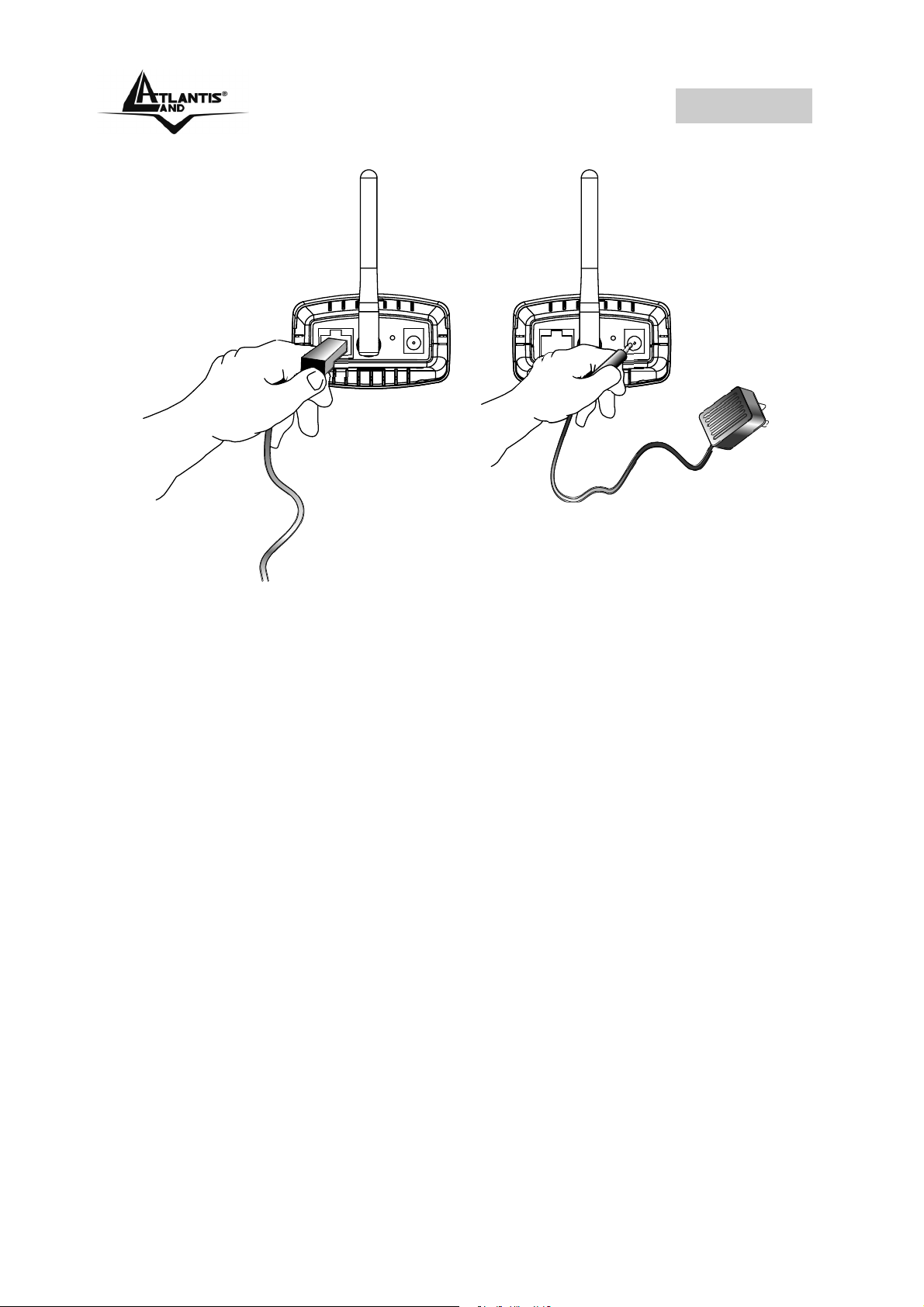
Collegare a questo punto la NetCamera alla LAN utilizzando
il cavo fornito in dotazione. Per terminare collegare
l’alimentatore.
9
Page 10
ITALIANO
Verificare che il LED Power sia acceso.
10
Page 11

ITALIANO
1.5 Settaggi di Default
Prima di iniziare la configurazione dell’Atlantis NetCamera è
necessario conoscere quali siano i settaggi di default:
• Password:
• Username:
• Indirizzo IP: 192.168.0.20
• SSSID=stringa vuota, Canale=11
1.6 Configurazione IP Security Cam
Accedere col browser web al seguente indirizzo IP che di
default è: http://192.168.0.20, e premere il tasto invio.
Apparirà a questo punto il Menù Principale. Nella parte
sinistra è possibile accedere (come se si stessero vedendo i
links in una homepage) a tutte le sezioni disponibili: View
Image ActiveX Mode, View Image Java Mode, System
Administration.
Il PC da cui si effettua la configurazione
deve avere un IP nella stessa classe
della NetCamera (esempio 192.168.0.1
e subnet mask=255.255.255.0)
11
Page 12

ITALIANO
Cliccando sulla sezione desiderata, nello spazio della
homepage appariranno tutti i settaggi relativi alla
configurazione della sezione scelta, oppure si apriranno
tutta una serie di sottosezioni tra cui scegliere prima di
avere accesso alle configurazione vere e proprie.
1.7 Java/ActiveX Mode
Cliccare su “View Image – Java Mode/ActiveX” dal menù
principale per avere accesso alla schermata sotto
raffigurata.
12
Page 13

ITALIANO
Camera Name*
Date/Time***
Camera Name* - Il nome della Camera mostrato è
contenuto nel campo Camera Name in System.
Date/Time***- Viene mostrata l’ora e la data attuale.
E’ possibile configurare nel dettaglio le
funzioni E-Mail Upload ed Image
Upload accedendo all’opportuna
sezione
Nella modalità ActiveX è necessario
installare l’opportuno Plug-In presente
nel CDRom a corredo
13
Page 14

ITALIANO
1.8 System Administration
In questa sezione è possibile configurare nel dettaglio il
dispositivo. Consultare il manuale completo presente nel
CDRom a corredo.
1.9 Supporto Offerto
Per ogni problema con questo dispositivo consultare il
anuale completo fornito a corredo sul CDRom.
Per qualunque altro problema o dubbio è possibile
contattare l’help desk telefonico (02/93907634) gratuito di
Atlantis Land che fornirà assistenza da lunedì al giovedì
dalle 9:00 alle 13:00 e dalle 14:00 alle 18:00. Il venerdì dalle
9 :00 alle 13 :00. E’ possibile anche utilizzare il fax
(02/93906161) la posta elettronica (info@atlantis-land.com
oppure tecnici@atlantis-land.com).
AtlantisLand spa
Viale De Gasperi 122
20017 Mazzo di Rho(MI)
Tel: 02/93907634(help desk)
Fax: 02/93906161
Email: info@atlantis-land.com
land.com (mettere nell’oggetto il codice del prodotto di
cui si chiede assistenza)
WWW: http://www.atlantisland.it
land.com
oppure tecnici@atlantis-
o www.atlantis-
14
Page 15

ENGLISH
Copyright Statement
No part of this publication may be reproduced, stored in a
retrieval system, or transmitted in any form or by any means,
whether electronic, mechanical, photocopying, recording or
otherwise without the prior writing of the publisher.
All copyright reserved.
The Atlantis Land logo is a registered trademark of Atlantis
Land SpA. All other names mentioned mat be trademarks or
registered trademarks of their respective owners. Subject to
change without notice. No liability for technical errors and/or
omissions.
15
Page 16

ENGLISH
For more detailed instructions on configuring and using
the NetCamera, please refer to the online manual.
1.1 Package contents
Atlantis Land NetCamera, CDRom with manual and IPView
SE, Quick Start Guide, cable CAT-5 LAN, Antenna, Power
Adapter AC-DC (5V, 2.5A) and Camera Stand Accessory.
1.2 The Front Panel LEDs
LED Meaning
1 Power Lit when power ON
Link LED
Power LED
2 Link
Lit when connected to Ethernet device
Orange for 100Mbps
Blinking when data transmit/received
16
Page 17

ENGLISH
1.3 The Rear Ports
10/100 Ethernet
DC Power
ANT
Connector
Reset
Network
Cable
Antenna
Connector
Port Meaning
1 Network Cable
2 Antenna
Connector
DC 5V
Reset Button
The Wireless Internet Camera’s
rear panel features an RJ-45
connector for connections to
10Base-T Ethernet cabling or
100Base-TX Fast Ethernet
cabling
There is the SMA type antenna
connector located on the rear
panel of the Wireless Internet
3 Reset Button
Camera, providing connection
for one high sensitivity antenna
included in the package
After the device has turned on,
press it to reset the device or
restore to factory default
settings. The operation is as
below:
1 seconds: reset the device
3 seconds: seconds or above:
restore to factory default
17
Page 18

ENGLISH
settings
4 POWER (jack)
Connect the supplied power
adapter to this jack
1.4 Cabling
The NetCamera comes with a camera stand with a swivel
ball screw head that can be attached to the Wireless Internet
Camera's bottom screw hole. Attach the camera stand to
the NetCamera and station it for your application. There are
three holes located in the base of the camera stand allowing
the Wireless Internet Camera to be mounted on the ceiling
or any wall securely.
From the rear panel of the Wireless Internet Camera, screw
the external Antenna that came with the Wireless Internet
Camera into the antenna connector.
18
Page 19

ENGLISH
Connect an Ethernet cable to the network cable connector
located on the Wireless Internet Camera’s rear panel, and
then attach it to the network. Attach the external power
supply to the DC power input connector located on Wireless
Internet Camera’s rear panel, and then connect it to your
local power supply.
Confirm power source is supplied from the LED indicators
label Power on the Wireless Internet Camera is illuminated.
1.5 Default Settings
Before you configure this IP (wireless) Security Cam, you
need to know the following default settings:
• Password:
• Userneme:
• IP address : 192.168.0.20
• SSSID= Null String , Channel=11
19
Page 20

ENGLISH
1.6 Browser configuration
Open the web browser, enter the local port IP address of this
IP Wireless Security Cam, which default at
http://192.168.0.20, and click “Go” to get the login page.
At the configuration homepage, the left navigation pane
where bookmarks are provided links you directly to the
desired setup page, including: View Image ActiveX Mode,
View Image Java Mode, System Administration.
1.7 Java/ActiveX Mode
To view video images from the browser, click “View Image –
ActiveX Mode / Java Mode” from the welcome screen to
access the video images from Internet Explorer as illustrated
below:
20
Page 21

ENGLISH
Camera Name*
Date/Time***
Camera Name* - The Camera name will be display when
the Camera Name field is entered in the Web Configuration
setting under System.
Date/Time***- The date/time of the video server will show
the date and time that come from time server or you set
manually.
Administrator has the authority to set
the email image functions through the
setting in the “E-mail” of System
Administration menu bar.
The Administrator has the authority to
allow the users to set the image upload
functions through the setting in the
“Upload” of System Administration
menu bar
Please refer to the appendix on how to
install ActiveX.
Install to the Web Server
Install to your Local PC
21
Page 22

ENGLISH
1.8 System Administration
For more detailed instructions on configuring and using the
NetCamera, please refer to the online manual.
1.9 Support
If you have any problems with this device, please consult the
full manual on CDRom. If you continue to have problems
you should contact the dealer where you bought this device.
If you have any other questions you can contact the Atlantis
Land company directly at the following address:
Atlantis Land SpA
Viale De Gasperi, 122
20017 Mazzo di Rho(MI)
Tel: +39. 02.93906085, +39. 02.93907634(help desk)
Fax: +39. 02.93906161
Email: info@atlantis-land.com
WWW: http://www.atlantis-land.com
or tecnici@atlantis-land.com
22
Page 23

FRANCAIS
Copyright
Copyright . 2002 est la propriété de cette société. Tous
droits réservés. Sont interdites, la reproduction, la
transmission, la transcription, la mémorisation dans un
système de sauvegarde où la traduction dans une autre
langue ou en langage informatique quels qu’ils soient, de la
présente publication, sous quelque forme que ce soit ou
quel qu’en soit le moyen, électronique, mécanique,
magnétique, optique, chimique, manuel ou de tout autre
genre, sans avoir obtenu au préalable le consentement de
notre entreprise.
23
Page 24

FRANCAIS
Ce guide d’installation rapide vous permet d’installer et de
configurer la NetCamera suivant des paramètres standards.
Pour plus de précisions, tant sur les méthodes de
configuration que sur le paramétrage avancé, reportez-vous
au manuel sous format électronique (PDF) disponible sur le
CDRom fourni.
1.1 Contenu de la boîte
Avant l’installation, assurez-vous de disposer des éléments
suivants : Atlantis Land NetCamera, CDRom avec
Application IPView SE, Manuel, Guide d’installation rapide,
Câble réseau RJ45 (Cat 5), Antenne, Adaptateur secteur et
Pied metallique.
1.2 Face avant
LED Link
LED Power
Alimentation
24
Page 25

FRANCAIS
LED Signification
Allumée quand l’IP Security Cam est
1 Power
sous tension
Allumée quand le LAN (réseau) est
connecté
2 Link
Orange= connexion à 100Mbps
Clignote lors des transferts de
données
1.3 Face arrière
10/100 Ethernet
Cable
Réseau
ANT
Antenne
Reset
DC 5V
Bouton Reset
DC
Alimentation
Port Usage
Reliez directement avec un
1
Cable réseau
câble Ethernet standard ou
croisé aux PC ou à un port
uplink (Hub/Switch).
Vissez l'antenne à ce
2
Antenne
Bouton Reset
connecteur
Dispositif allumé, pressez pour
3
(remise à
effectuer le reset ou la
25
Page 26

FRANCAIS
zéro)
Prise
4
d’alimentation
restauration usine.
1 secondes: reset (remise à
zéro)
3 secondes: retour aux
conditions initiales
Connectez l’alimentation fournie
à cette prise
1.4 Câblage
L’IP Security Cam, qui est équipée de pas de vis sur les
faces supérieure et inferieure, est livrée avec un pied
orientable permettant de la fixer dans toutes les positions
(table, mur, plafond).
Fixez à l’arrière de la Wireless Internet Camera, l’antenne
fournie.
26
Page 27

FRANCAIS
Reliez votre IP Security Cam à votre réseau avec un cable
adapté puis l’alimentation secteur fournie.
Vérifiez que la LED Power est allumée sur la face avant de
votre IP Security Cam.
1.5 Configuration initiale
Avant de commencer la configuration de l'IP Wireless
Security Cam, il est nécessaire d’en connaître la
configuration par défaut :
• User:
• Password :
• Adresse IP: 192.168.0.20
• SSID= vide, Canal=11
27
Page 28

FRANCAIS
1.6 Configuration avec le Browser
Pour accéder à l’interface Web, lancez un navigateur
Internet et tapez dans la barre adresse l’IP suivante :
http://192.168.0.20
Vous entrerez dans le Menu Principal, dans la partie gauche
on accédera à toutes les sections: View Image ActiveX
Mode, View Image Java Mode, System Administration.
1.7 Java/ActiveX Mode
Cliquer sur "View Image - Java Modes/ActiveX" du menu
principal. L'image suivante apparaîtra.
28
Page 29

FRANCAIS
Camera Name*
Date/Time**
Camera Name* - Le nom de l’IP Security CAM que l’on
retrouve dans le champ Camera Name du menu System
Administration.
Date/Time**- L'heure et la date actuelles.
Ppour la configuration E-mail Upload et
Image Upload consulter le manuel
contenu sur le CDRom fourni
Pour la modalité ActiveX, il est
nécessaire d'installer le Plug-in contenu
sur le CDRom fourni
29
Page 30

FRANCAIS
1.8 System Administration
Dans cette section, vous pouvez configurer plus en détails
l’IP Security CAM. Consultez le manuel complet présent
dans le CDRom pour de plus amples renseignements.
1.15 Support
Pour tous problèmes ou renseignements, vous pouvez
contacter la « help desk » téléphonique gratuite d’Atlantis
Land qui vous fournira assistance du:
lundi au vendredi de 9.00 à 13.00 et 14.00 à 18.00
Vous pouvez aussi nous contacter par email :
tech-fr@atlantis-land.com
Atlantis Land France
57, Rue d’Amsterdam
75008 Paris
WWW: http://www.atlantis-land.fr
Seulement pour la France
Important :
Pensez à consulter notre site Web, pour prendre
connaissance d’éventuelles mises à jour de Firmware,
clauses de garantie, etc...
30
Page 31

NOTE
31
Page 32

NOTE
32
Page 33

Where solutions begin
Company certified ISO 9001:2000
Atlantis Land S.p.A.
Viale De Gasperi, 122
Mazzo di Rho – MI – Italy
info@atlantis-land.com
sales@atlantis-land.com
www.atlantis-land.com
 Loading...