

Page 1
ADDRESS: ATLANTIC BOILERS, PO BOX 11, ASHTON UNDER LYNE, OL6 7TR
WEB: WWW.ATLANTICBOILERS.COM EMAIL: [email protected]
TEL: 0161 621 5960 FAX: 0161 621 5966
VF Model
INSTALLATION &
MAINTENANCE
WALL-MOUNTED GAS CONDENSING BOILER
40, 60, 80 & 100KW OUTPUT
MODULATING BURNERS
After sales service is guaranteed by Atlantic Boilers
The boilers conform to the following CE Directives
Directive 2006/95/CD - low voltage
Directive 2004/108/CEE - electromagnetic compatibility
Directive 92/42/CEE - efficiency
Directive 90/396/CEE - gas fired equipment
Page 2

0RNOxxxx-#_TR Installation Entretien VARFREE page 2/41
Summary
1. Dimensions and components ...............................................................................................5
1.1. Dimensions....................................................................................................................................... 5
1.2. VF Components ................................................................................................................... 6
2. Technical Characteristics ................................................................................................. 7
2.1. Acceptable gas pressure .................................................................................................................7
2.2. Combustion conditions...................................................................................................................... 7
2.3. Operating conditions......................................................................................................................... 8
2.4. Electrical conditions.......................................................................................................................... 8
3. Installation ..............................................................................................................................9
3.1. UK Regulations................................................................................................................................... 9
3.2. Single boiler installation......................................................................................................................9
3.3. Multi-boiler installtion. ......................................................................................................................10
3.4. Flue gas pipework connection to boiler............................................................................................ 11
3.5. Conventional flue arrangement........................................................................................................16
3.6. Balanced flue arrangements............................................................................................................18
3.7. Heating pipework connections......................................................................................................... 18
3.8. Gas pipework connections............................................................................................................... 20
3.9. Internal electrical connections.......................................................................................................... 21
3.10. External electrical connections........................................................................................................21
3.11. VARFREE wiring connections.........................................................................................................21
4. Boiler Control Panel.............................................................................................................22
4.1. Control panel fascia........................................................................................................................22
4.2. Control panel display arrangements...............................................................................................22
4.3. Control panel functions...................................................................................................................23
4.4. Adjustment of the settings .............................................................................................................. 25
4.5. Information on boiler condition........................................................................................................ 26
4.6. Adjustin the settings........................................................................................................................ 29
5. Function of the LMU64 060D168 Controller.......................................................................30
6. Commissioning.....................................................................................................................30
6.1. Check all preparatory conditions..................................................................................................... 30
6.2. Adjustment of the gas pressure...................................................................................................... 31
6.3. Commission ...................................................................................................................................33
7. Checks after commissioning ..............................................................................................33
7.1. Check for correct draining of condensate.......................................................................................33
7.2. Check for correct flow of gas..........................................................................................................33
7.3. Check that maintenance can be properly carried out......................................................................33
8. Maintenance Operations......................................................................................................33
8.1. Annual maintenance.......................................................................................................................34
8.2. Draining the boiler...........................................................................................................................35
9. Spares lists ........................................................................................................................... 36
9.1. VF 60 ................................................................................................................................36
9.2. VF 100 ...............................................................................................................................37
9.3. VF control panel..................................................................................................................38
Page 3

page 4/41
10. Adjustment of parameters................................................................................................. 39
11. Installation of Condensate Siphon ...................................................................................42
11.1. VF 60 Siphon....................................................................................................................42
11.2. VF 100..............................................................................................................................43
11.3.VF safety valve.................................................................................................................. 44
Page 4
page 5/41
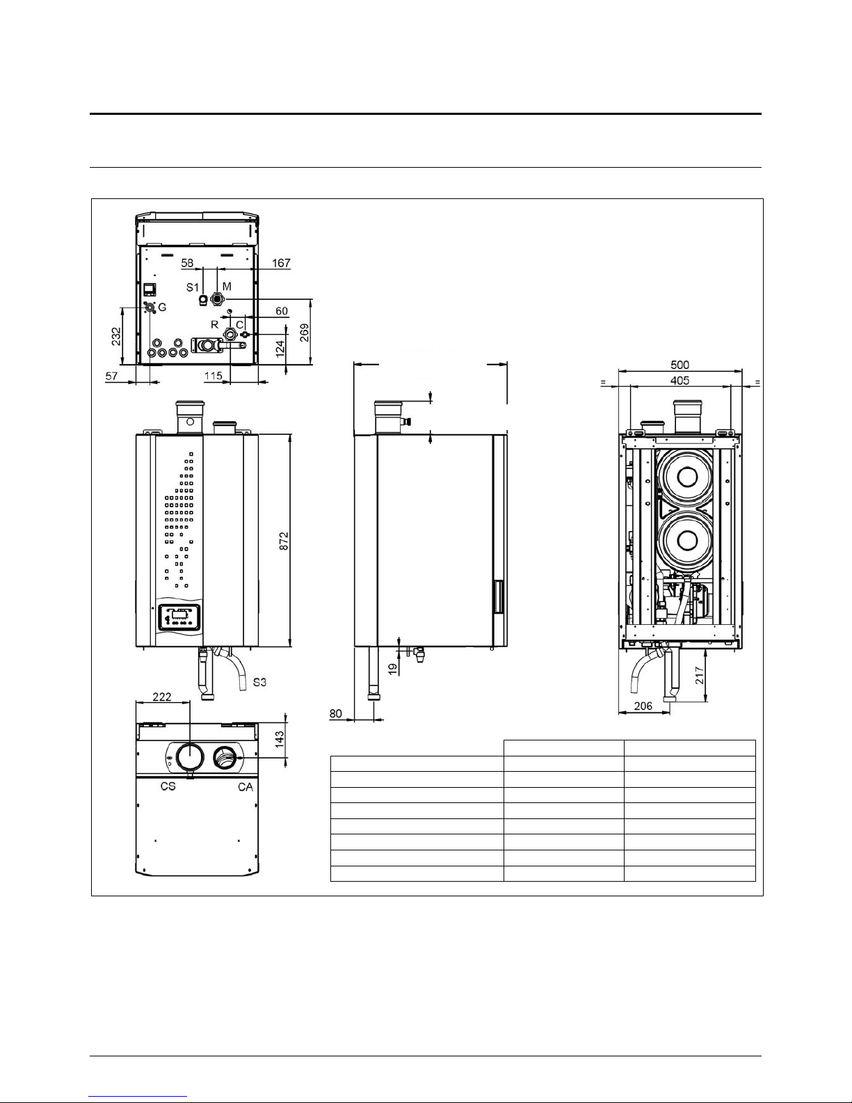
1. Dimensions and Components
1.1. Dimensions
model 40 and 60 = 472
model 80 and 100 = 626
model 60 = 125
model 100 = 135
VF 40 / 60 VF 8
0 / 100
R heating return G 1’’ G 1’’ 1/4
M heating flow G 1’’ G 1’’ 1/4
G gas inlet G ¾’’ G ¾’’
C water feed inlet G ½’’ G ½’’
S1 safety valve ½’’ ½’’
CA combustion air inlet Ø 80 Ø 80
CS flue gas outlet Ø 80 Ø 100
S3 condensate outlet Ø 22 Ø 22
Page 5
page 6/41
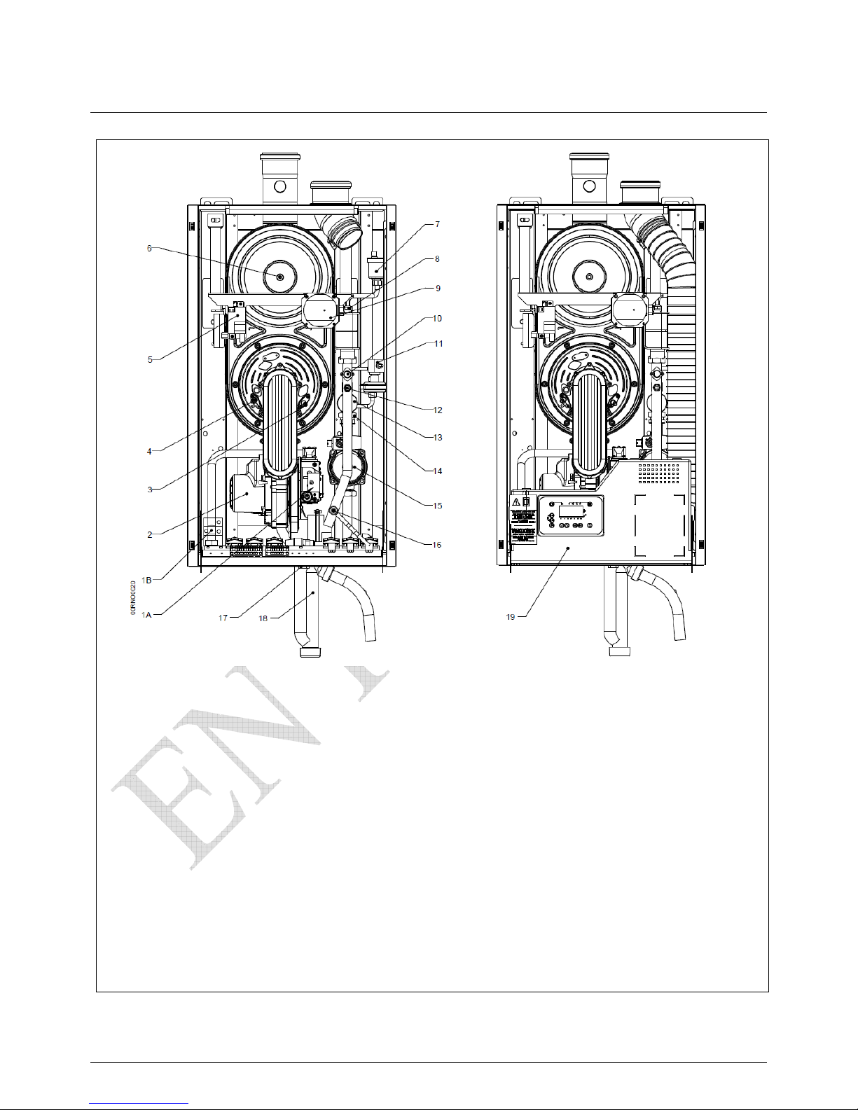
1.2. VF Components
1A – gas valve models 40 / 60
1B – gas valve models 80 / 100
2 – combustion air fan
3 – ionisation probe
4 – ignition probe
5 – ignition transformer
6 – flue gas temperature sensor
7 – automatic air vent
8 – return water temperature sensor
9 – differential air pressure switch
10 – high limit thermostat
11 - differential water pressure switch
12 – flow water temperature sensor
13 – water pressure switch
14 – non-return valve
15 – heating circulation pump
16 – drain valve
17 – safety valve (supplied loose)
18 – condensate siphon (supplied loose)
19 - control panel
Page 6
page 7/41
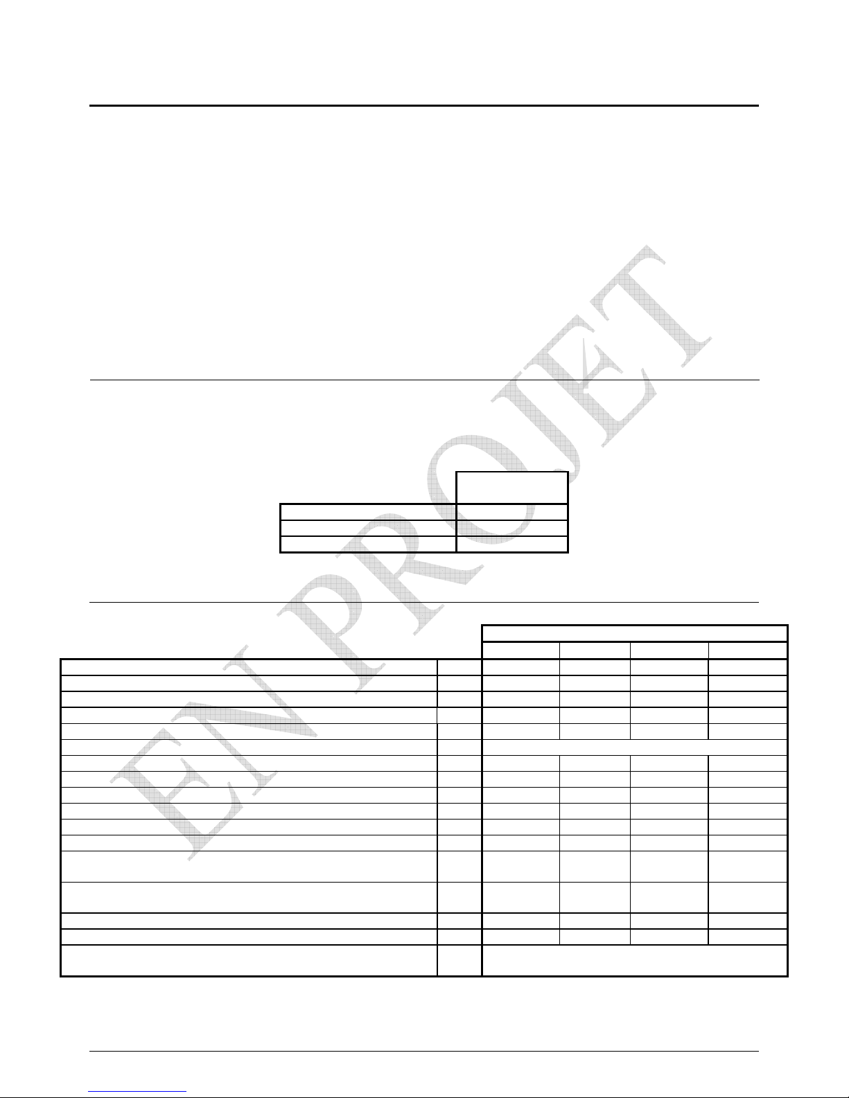
2. Technical Characteristics
The V F boiler is set in the Factory to operate
on Natural Gas Group H with a supply pressure of 20mBar.
For higher gas pressure up to 300mBar, a filter and
a pressure regulator must precede the V F gas valve.
2.1. Acceptable gas pressure
Gaz naturel H
G20
Nominal (mbar)
20
Minimum (mbar)
17
Maximum (mbar)
25
2.3. Combustion conditions
VF
40 60 80 100
Nominal output Pn (80/60°C)
kW
56,5
92,6
Nominal condensing output P (50/30°C)
kW
61,8 100
Nominal heat outflow Qn
kW
58 95,1
Minimum heat outflow Qmin
kW
14,5 25,5
G20 gas flow rate at Pn
m
3
/h 6,1 10,1
Recommended CO2 values
% see chapter 6.2
Mass flow of flue gases Qn / Qmin (80/60°C)
g/s 27 / 6,1 44 / 12
Mass flow of flue gases Qn / Qmin (50/30°C)
g/s 25,3 / 5,7 39,6 / 10,4
Temperature of flue gases Qn / Qmin (80/60°C)
°C 70 / 55 76 / 60
Temperature of flue gases Qn / Qmin (50/30°C)
°C 46 / 32 56 / 32
Pressure loss for flue gas circuit Qn
Pa 75 74
Diameter of flue gas outlet mm 80 100
Maximum pressure at flue gas output (B23P)
Qn / Qmin (80/60°C) *
Pa 150 / 8 110 / 6
Maximum pressure at flue gas outlet (B23P)
Qn / Qmin (50/30°C) *
Pa 123 / 3 97 / 5
Combustion air at Qn
m
3
/h 76 124
NOx class to EN 483:2000 4 / 5 5 / 5
Types of flue gas and combustion air arrangements
B23, B23P, C13, C33, C53
Page 7
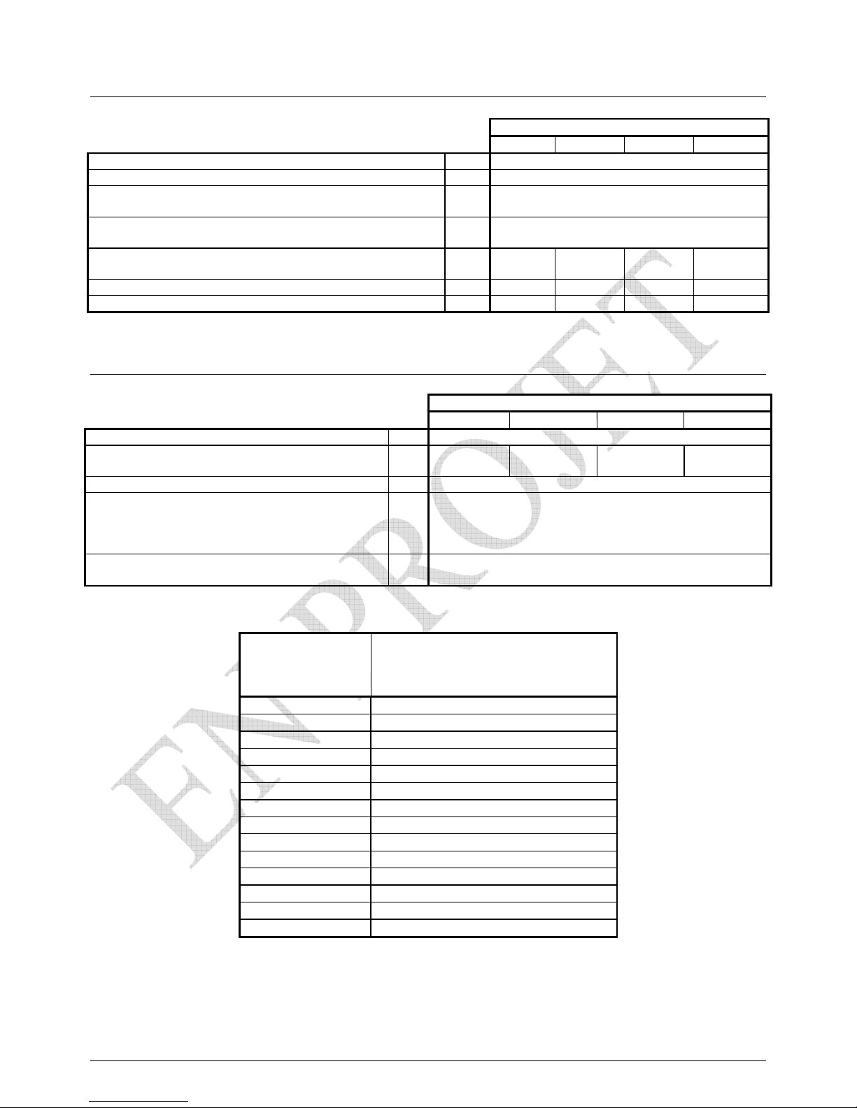
page 8/41
2.3. Operating conditions
VF
60 100
Maximum flow water temperature °C 80
Temperature Limit thermostat °C 100
Maximum working pressure
hPa
(bar)
4000
(4,0)
Minimum working pressure
hPa
(ba
r)
1000
(1,0)
Minimum water flow rate :
primary / secondary circuits (P/20)
l/s 0.67 / 0.67 1.11 / 1.11
Water content
l 6,1 9,4
Dry weight
kg 73 88
2.4. Electrical conditions
VF
60 100
Electrical supply
V 230 V AC (+10% -15%), 50Hz
Requirement at Qn
W 190 300
Requirement at standing load
W 7
Maximum length for sensor cables
m
domestic hot watersensor : 10
external sensor : 40
room thermostat : 40
room sensor : 50
Control panel requirement
V
A
230V AC (+10%, -15%)
5 mA à 1 A
Temperature °C
Ohm resistance
flow/return sensor QAK36.095/109
flue gas sensor QAK36.670/109
NTC 10 KΩ at 25°C
0°C
32 555 Ω
10°C
19 873 Ω
20°C
12 488 Ω
25°C
10 000 Ω
30°C
8 059 Ω
40°C
5 330 Ω
50°C
3 605 Ω
60°C
2 490 Ω
70°C
1 753 Ω
80°C
1 256 Ω
90°C
915 Ω
100°C
677 Ω
110°C
508 Ω
120°C
387 Ω
Page 8
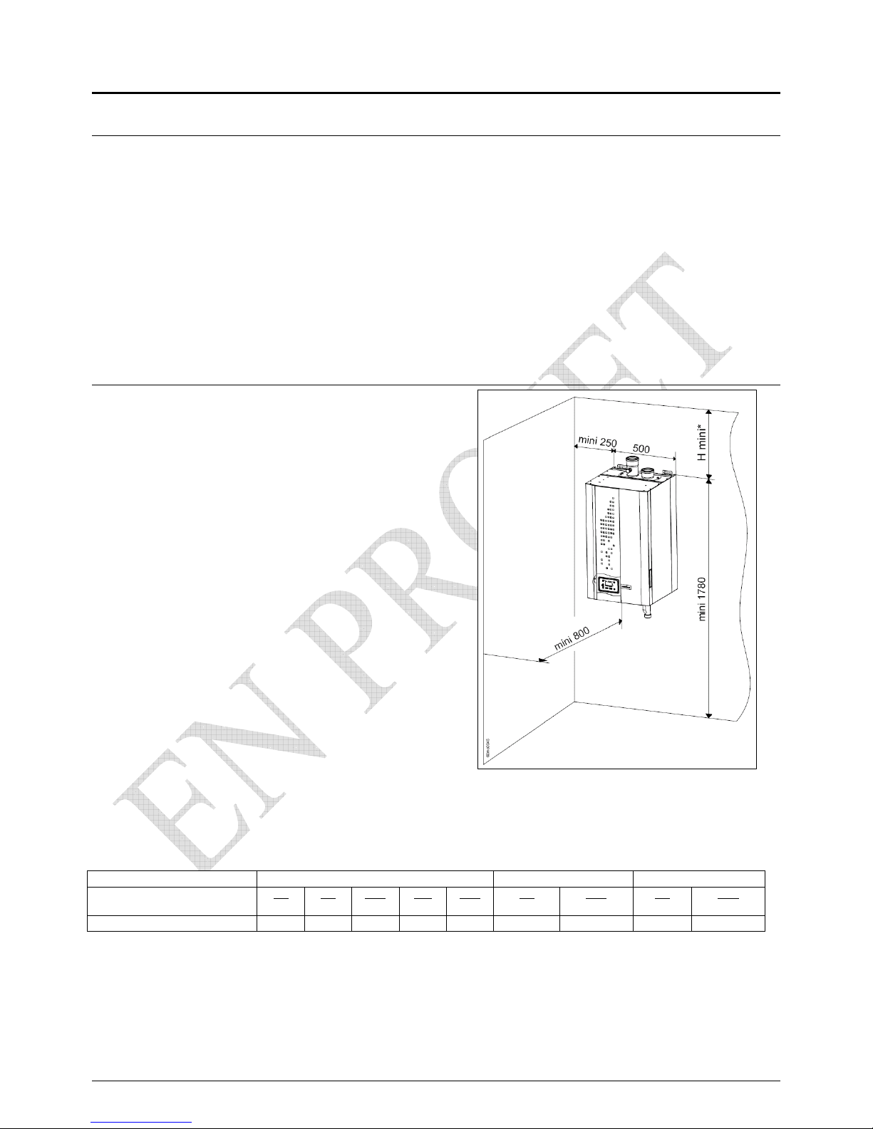
page 9/41
3. Installation
3.1. UK Regulations
The V F installation must be installed and maintained according to the
Recommendatios of this Manual, the recommended cods of practice of the CIBSE
the BSI, the BSRIA and the ATLANTIC BOILERS commissioning check list
3.2. Single boiler installation
The VF must not be installed on an inflammable surface,
the air for combustion must not include agents arising from
aerosols, paints, adhesives detergents etc. Equally the air must
not be drawn from locations where similar agents are present,
such as swimming pools, dry cleaners and hair dressing salons.
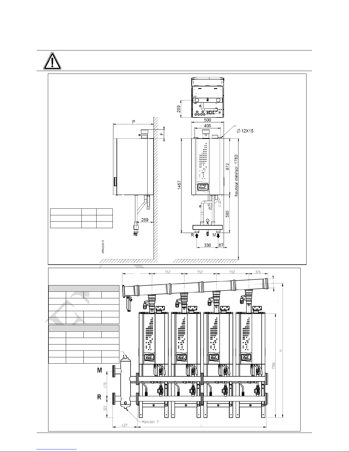
Clearance around the VF
The access space around the boiler are shown on
the adjoining drawing
These spaces may alter where influenced by specific
requirements
The dimensions H will vary according to the types of flue
outlet and air inlet which are explained in section 3.4
type exhaust fumes B23/B23P C13/C33 C53
VF
60
Ø110
60
Ø125
100
Ø110
100
Ø125
100
Ø160
60
Ø80/125
100
Ø100/150
60
Ø80/80
100
Ø100/100
H mini*
405 475 465 450 655 475 525 310 350
Page 9
page 10/41
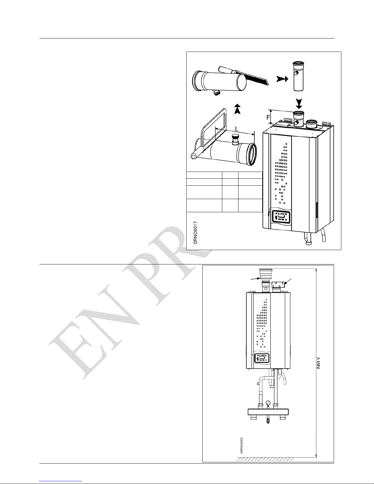
3.3. Multi-boiler installation
Important : With one boiler or several, it is essential that a balancing vessel
is also installed.
The boiler(s) must not carry the weight of the balancing vessel
Wall fixing with
Ø 2x M10 screws
Installation of one VF
with a balancing vessel
M:heating circuit flow
R:heating circuit return
VF 60 100
F
125 135
P
472 626
Installation of 4 VF
in cascade
M:heating circuit flow
R:heating circuit return
Model 60
Nbre 2 3 4
A 507
Ø B 160
H 2235 2265 2295
L 1122 1674 2226
A
Ø B
Model 100
Nbre 2 3 4
A 532
Ø B 200
H 2393 2423 2453
L 1122 1674 2226
Page 10
page 11/41
3.4. Flue gas pipework connection to boiler
Important : The boiler(s) must not carry the weight of the flue assembly
The flue offtake from the boiler should include
a tapping to allow analysis of the combustion
gases.
To ensure correct readings, the offtakes should
have the lengths 'F' and 'L', as shown on the
adjacent drawing.
3.5. Conventional flue arrangement B23 and B23P
When fitting B23 and B23P, it is essential the
minimum dimension 'A' is observed. This allowes space
to adapt the flue to give a pressure at the boiler outlet of 0 Pa
The flue assembly must be resistant to condensate and
capable of withstanding temperatures up to 120°C
The VF boiler will have very low outlet temperatures;
consequently, to encourage lift of the flue gases and draining
of the ondensate, the flue pipework should slope upwards at
an incline of 3°C. In addition, to avoid leakage, the joints
should be sealed tightly using soapy liquid or an
appropriate grease.
adapter air filter
c
d
e
+5
0
+5
0
VF 60 100
Ø ext
80 100
F
125 135
L
160 170
Page 11
page 12/41
IMPORTANT
In a multi-boiler installation serving onto a flue header, ensure that
1.) calculations show the header is not in pressure when all boilers are operation
2.) When one boiler is off or on minimum output, all the boilers are not upset
Accessories B23-B23P Reference
VF 60
A
mini
100
A
mini
Flue gas adapter
+ air filter Ø 80
Ø80M / Ø110F : 059499
Ø80M / Ø125F : 059500
2000
2055
Ø100M / Ø110F : 059501
Ø100M / Ø125F : 059502
Ø100M / Ø160F : 059503
2060
2030
2195
For the B23P adaptor, the flue pipework must be capable of working under pressure
The range of pressures are given in section 2.3
Calculation ust prove that the total resistance will be within these parameters
Page 12
page 13/41
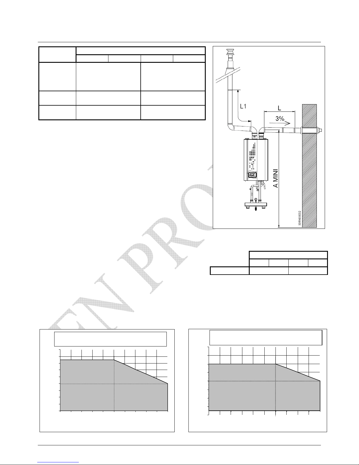
3.6 Balanced flue arrangement C53
VF
60 100
Balanced Vertical balanced flue Vertical balanced flue
flue kit 80/125 + combustion 100/150 +combustion
air terminal 80 air terminal 100+100/80
Black
flue
059510 059513
Brown
flue
059511 -
Take note of the acceptable balanced flue outlets
on the following pages
In calculating the length of a flue
Allow one metre equivalent for a 90degree elbow
Allow half a metre equivalent for a 45degree elbow
For both flue and combustion air pipes, a 3degree slope
upwards in direction of flow is recommended
0
2
4
6
8
10
12
14
16
18
02
4681
01214161820
L air inlet (m)
L1 flue
(m)
- maximum duct length Type C53 -
- VF 60 -
-1
1
3
5
7
9
11
13
15
02
4681
01214161820
L air inlet (m)
L1 f
lue (m)
- maximum duct length Type C53 -
- VF 100 -
VF
60 100
A (mm)
1890 2005
Page 13
page 14/41
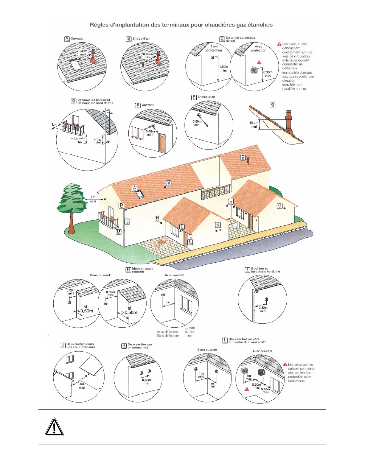
The dimensions given are the minimum requirements and they should be
exceeded if possible.
≤ 70 kW
Page 14
page 15/41
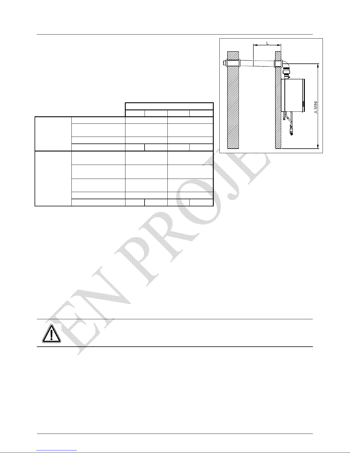
3.6 Balanced flue arrangement C13 and C33
The table below lists the components required for
this arrangement.
VF
60 100
Terminal C13
Code 059506 Code 059507
Ø of flue
Concentric
80/125
Concentric
100/150
A min (mm)
2125 2165
Horizontal
type C13
Lmax*
9 m 9** m
Terminal C33 noir
Code 059508 Code 059512
Terminal C33 ocre
Code 059509
-
Ø of flue
Concentric
80/125
Concentric
100/150
A mini (mm)
2035 2060
Vertical
type C33
Lmax*
9 m 9** m
* The dimension Lmax C13 + 90degC bend or C33
Calculations and recommendations carried out as on the previous page
For C13, make a 150mm hole in the wall for the 80/125 concentric flue
make a 180mm hole in the wall for the 100/155 concentric flue
** The V F 100 is set at Factory for balanced flues from 0-5 metres
for balanced flues between 5 metres and 9 metres, certain parameters
need adjustment as follows:-
Page 15
page 16/41
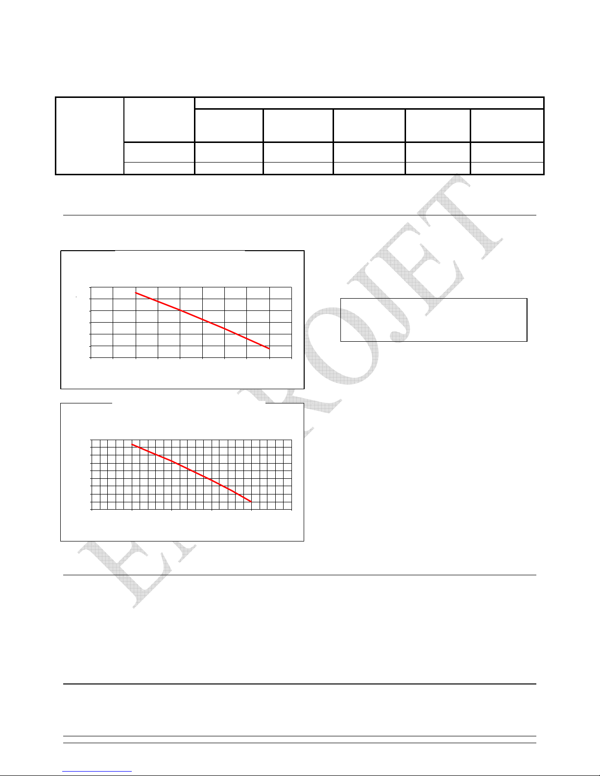
3.7. Heating pipework connections
3.7.1. Available pressure
Filling the Installation :
The system should be fully purged by flushing water through the header and boiler in turn.
.
Blockage may be caused by air locks and the autopmatic air vent can be used to solve this.
If the airlock is in the system, similar outlets must be found.
If a blockage occurs when the boiler is running, the error code E164
will appear on the control panel
On completion of filling :
• Check the system water pressure
minimum 1BAR, maximum 4BAR when hot
• Therefor generally set pressure on cold start at 1.5bars
Parameters LMU
Length of
balanced flue
L
H608
start
ignition
H609
start
H611
run
ignition
H612
run
low
H613
run
high
0 to 5 m
22,5 10,5 3500 1750 5900
VF
100
5 to 9 m 23 11,5 3600 1850 6400
Pressure available between
outlet M and inlet R of VF
e
0
5
10
15
20
25
30
35
40
45
0.55 0.69 0.83 0.97 1.11 1.25
water flow (l/s)
kPA
He
ad available
VF 100
0
5
10
15
20
25
30
0.44 0.47 0.5 0.52 0.55 0.58 0.61 0.63 0.66 0.69
water flow (l/s)
kPA
H
ead available
VF 60
Page 16

page 17/41
The condition of system water may reveal one or more of the following:-
1. excess acidity - reduce to PH 8.2 to 9.5
2. excess oxygen
3. excess metal particles
• to eliminate these, treatment must occur
•
.
•
Removal of condensate
Use a 32mm PVC as the condensate is PH 3 to 5
Page 17
page 18/41
3.8. Gas pipework connections
The VF gas train supllied has a 125 micron
pre-filter
If the gas supply is dirty, please fit an additional
50micron filter
Ensure there is a union fitted between the isolating
valve and the gas train
The gas train can accept a supply pressure between
17mBAR and 25mBAR
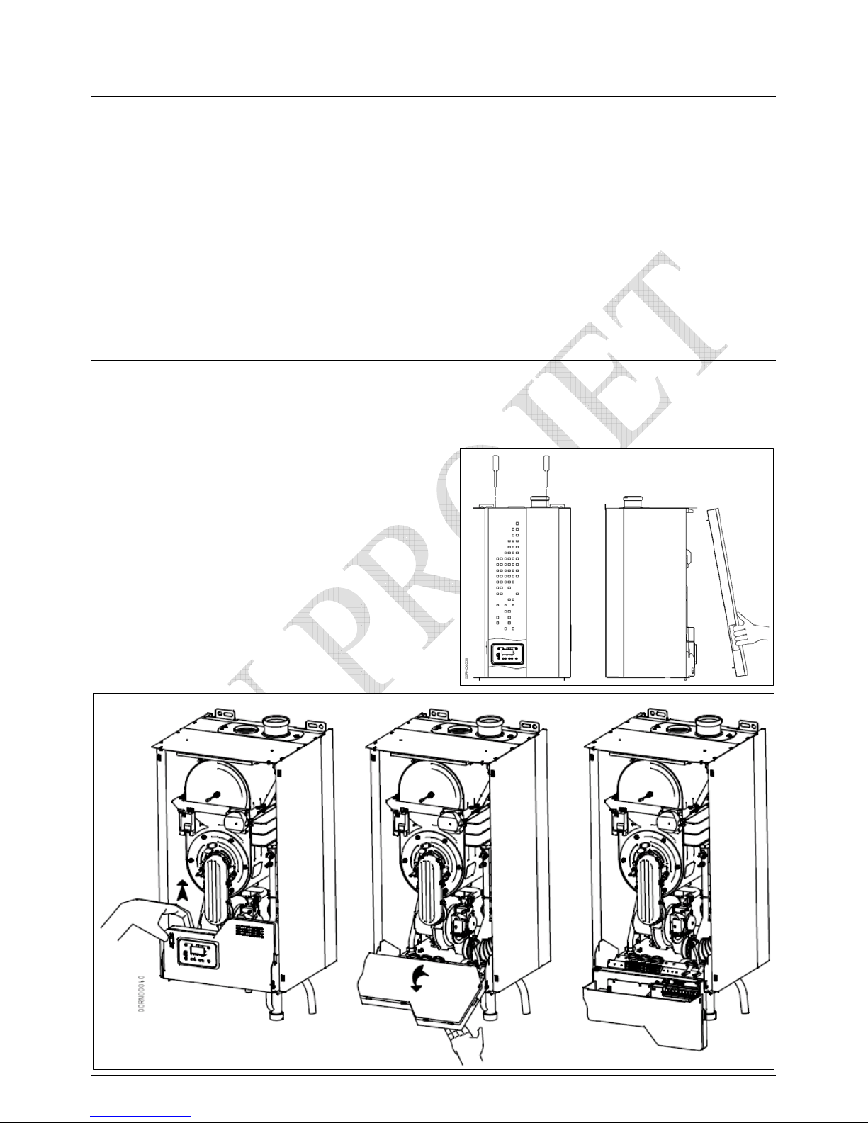
3.9. Internal electrical connections
For access to the electrical terminals on the rear of
the control panel:
1) remove two screws on the external front face
of the jacket
2) lift off the front face off the jacket
3) removing transport fixings, tilt the control panel
fully forward
4) the terminals are now accessible
5) use the prepared openings for the external cables
c
d
Page 18
page 19/41
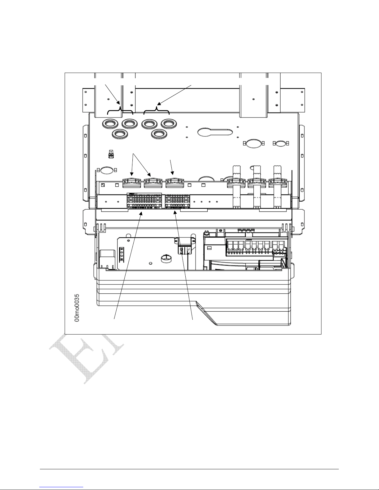
take care to note cable locations - polarities, neutral and earth
please observe BS15,100/2002 and EN 60 335-1
3 openings for power cables
3 openings for signal cables
2 power cable clips
1 signal cable clip
power terminals signal terminals
Page 19
page 20/41
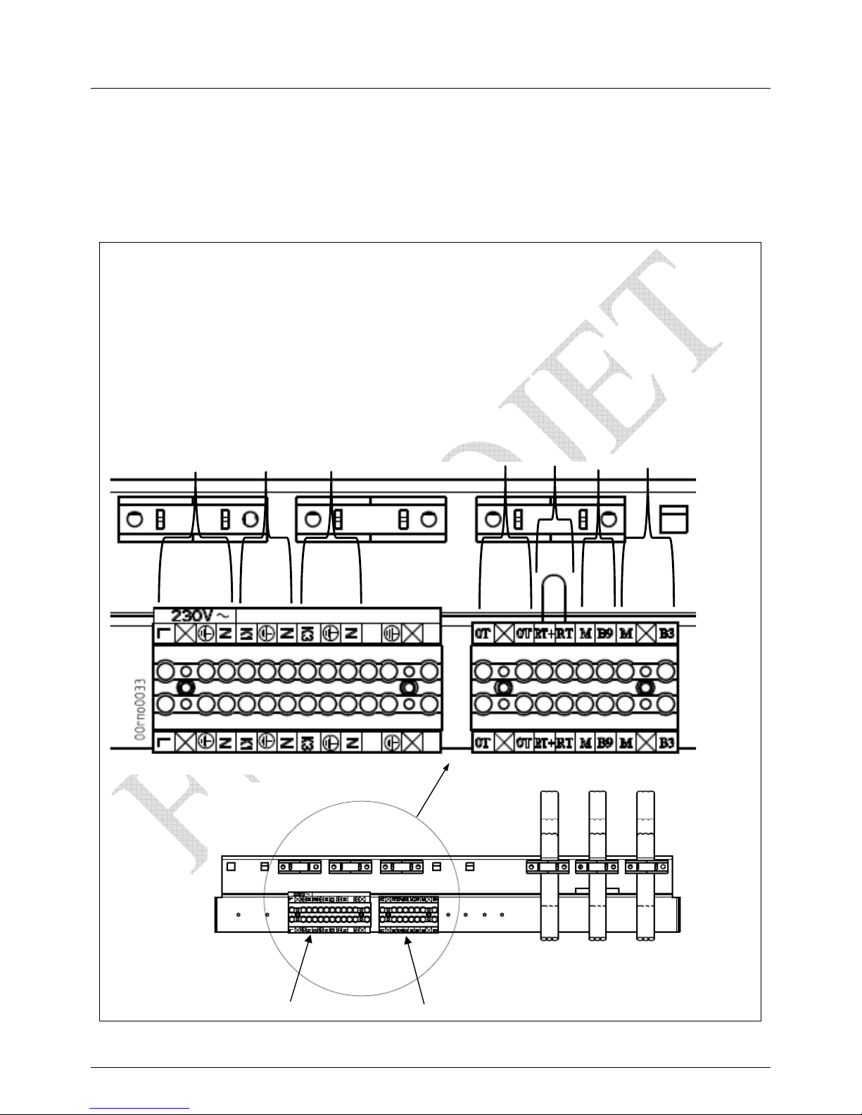
3.10. External electrical connections
Connections to the boiler must be permanent
The boiler must have a permanent isolator
Power terminals
Signal terminals
Power terminals Signal terminals
Power supply
3x1,5mm², ext 9 maxi
P
ower heating circulator
1 A
3x1,5mm², ext 9 maxi
Power DHW circulator
1 A
3x1,5mm², ext 9 maxi
Programmable space
control
Space thermostat
External sensor
DHW sensor
Page 20
page 21/41
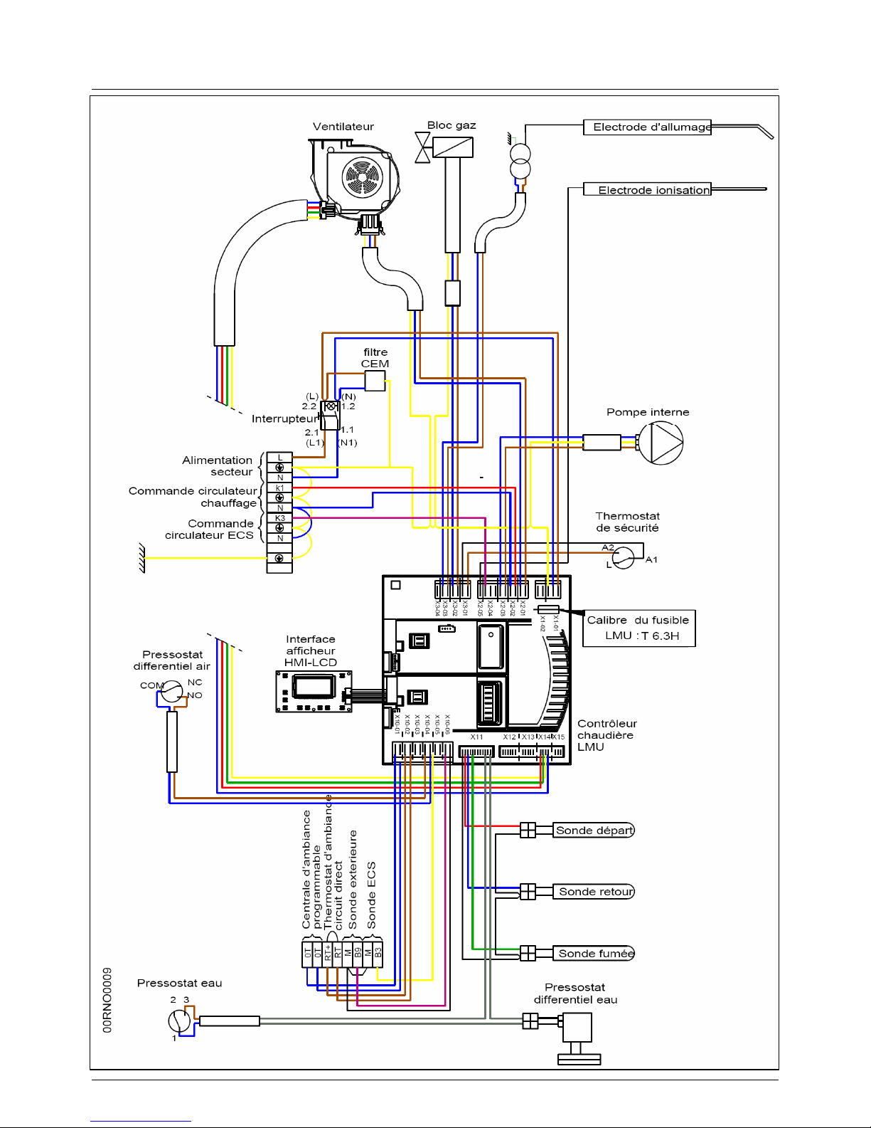
3.11. VF wiring connections
Page 21
page 22/41
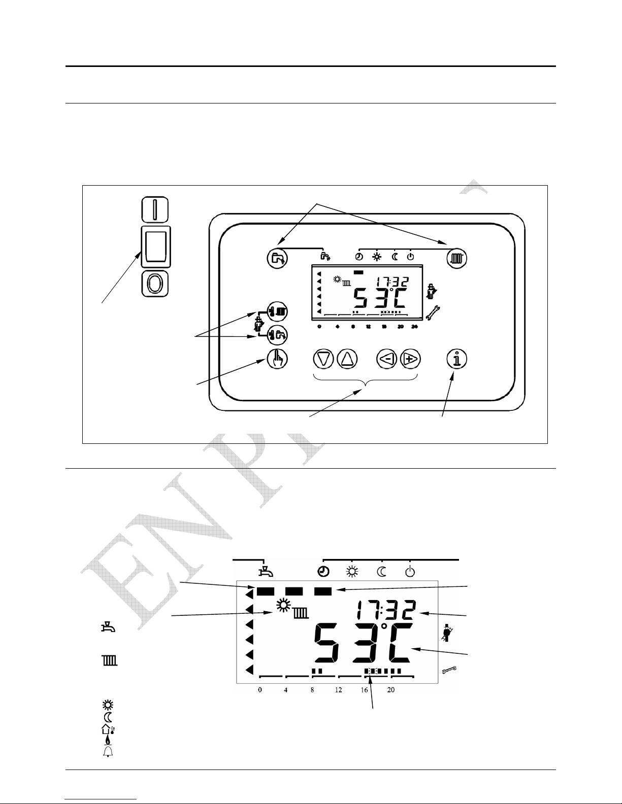
4. Boiler Control Panel
4.1. Control panel fascia
4.2. Display
The screen supplies boiler function, time, hourly programme,
temperature, burner, condition and defect
Hourly programme
Space heating
requirement
Time
Boiler
temperature
DHW requirement
Symbols :
DHW in progress
Space heating
in progress
Comfort requirement
Set back requirement
outside temperature
Flame established
Defect
Touch requirement
Touch programme Touch information
boiIer isolator
Touch signals
Touch
re-set
Page 22
page 23/41
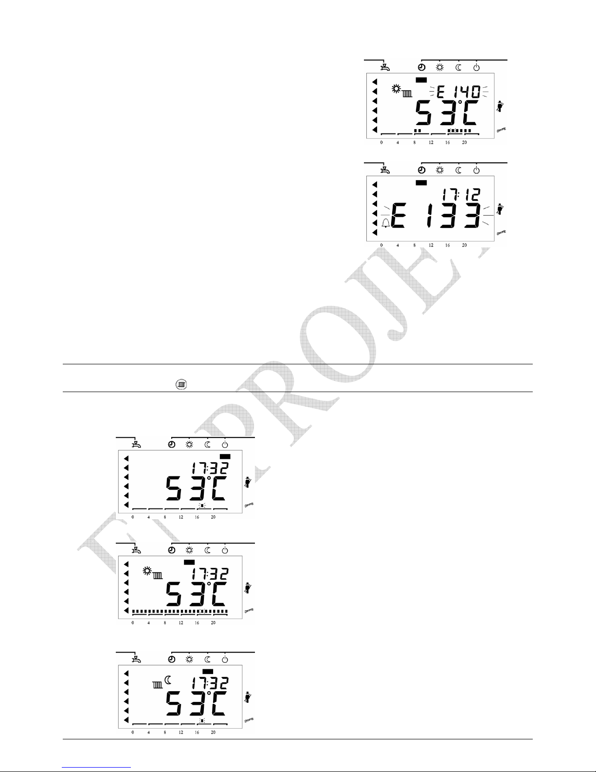
When a defect (not stopping the boiler) occurs, the defect code (as E140)
is displayed.
When a defect causes the boiler to lockout, the lock out code
as (E133) and a small bell is displayed. Check error list for explanation
4.3. Control panel functions
Touch radiator symbol
Selection of different heating requirements
Idle
No function of heating
L
cascade operation available
Comfort
Continuous heating on.
Boiler operation matches space heating
.
Eco
Continuous set-back heating
Page 23
page 24/41
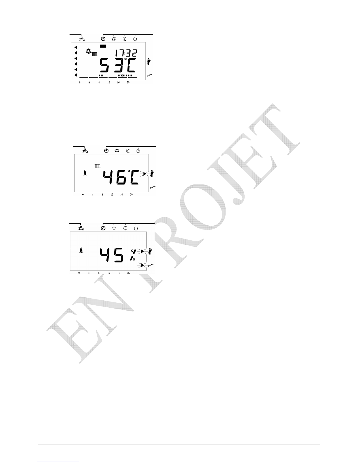
Auto SBoiler operation to time programme
between Comfort and Eco
Power C Boiler fires at full power for 3 seconds
Regulator Allows manual adjustment of the burner
Page 24
page 25/41
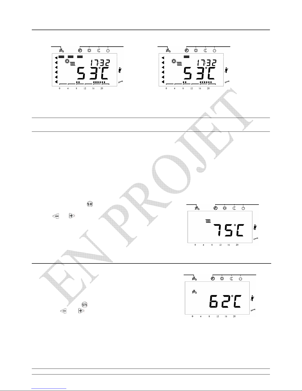
DHW in Operation DHW not active
4.4. Adjustment of the settings
Adjustment of the boiler constant flow temperature
In mode - boiler constant flow temperature
- regulation from 20degC to 80degC
In mode - external temperature
- regulation from 10degC to 26degC
•
•
Touch the radiator symbol
By touch
o r
select the boiler constant flow temperature
Touch the radiator symbol to fix the temperature
In mode - domestic hot water temperature
- regulation from 50degC to 65degC
.
Touch the tap symbol
o r
By touch on select the domestic hot water temperature
Touch the tap symbol to fix the temperature
Page 25
page 26/41
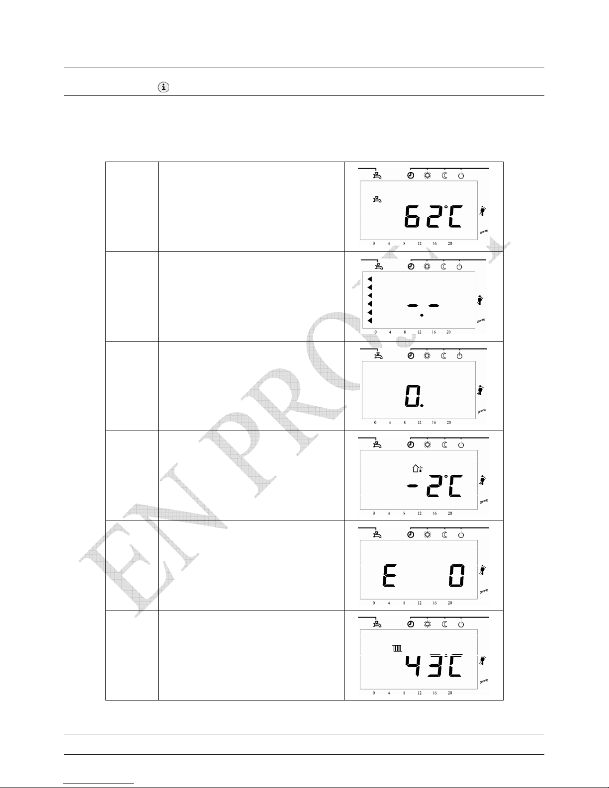
4.5. Information on boiler condition
Touch Information in order
1 DHW temperature
2 Out of action
3
Burner function
(see page 29)
4 Outside temperature
5
Error code
(see page 28)
6 Boiler flow temperature
To revert to standard display, press radiator or tap symbol
Page 26
page 27/41
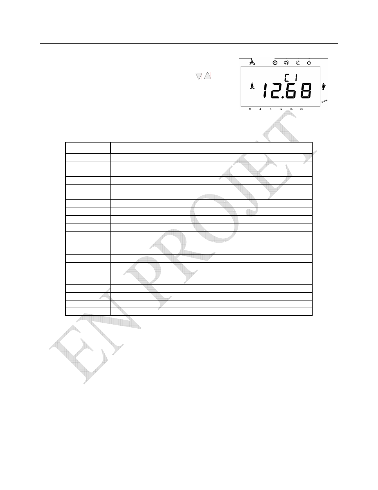
List of available information behind the Display
First touch - information
Press both vertical arrows simultaneously for 3 seconds
The time information is replaced by a letter (b,C,d) and a number (0 to 7)
By touching the vertical arrows, change the letter
By touching the + or -, change the number
Display Information
b0 Defect is present
b1 Boiler return temperature
b2 -
b3 Flue gas temperature
b4 Outside temperature
b5
b6
b7 Mixed flow temperature
C1
Ignition occuring (μA)
C2 Burner fan speed
C3 Burner fan PWM signal
C4 Output read from PMW
C5 -
C6 Correct output
d1
Recorded average boiler circuits flow temperature
d2 Recorded boiler flow temperature
d3 Recorded outside temperature
d4 Recorded DHW temperature
d5 Burner fan PWM recorded output
d6 Maximum speed of burner fan
Page 27
page 28/41
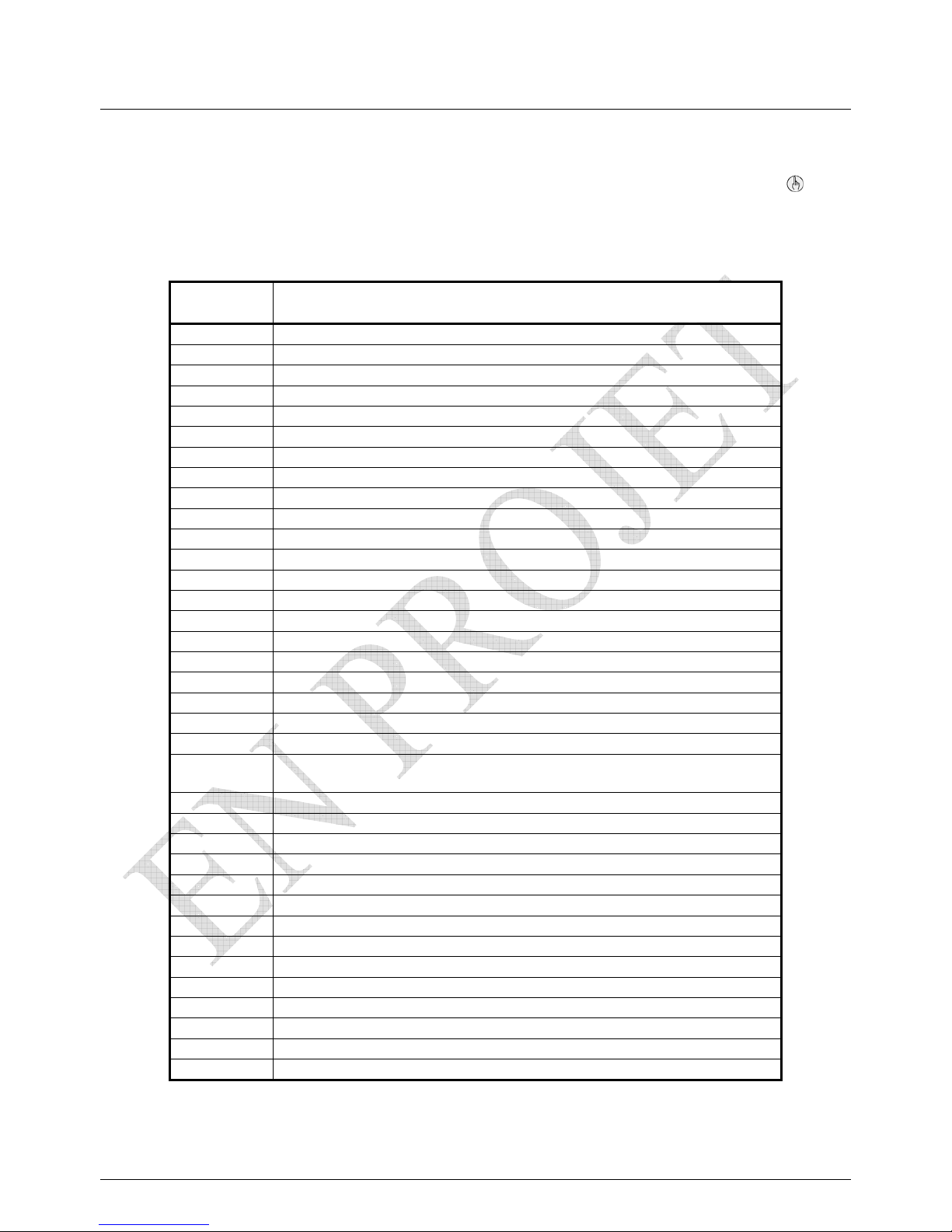
With a boiler defect leading to a lock-out on the LMU controller
the alarm signal is displayed against the defect indicator.
To re-set the LMU controller, clear the defect then press the re-set button for 2 seconds
Defects Indicator
Explanation
0
10 Faulty outside sensor
20 Faulty boiler flow sensor
28 Faulty flue gas sensor
32 Faulty clip-in sensor
40 Faulty boiler return sensor
50 Faulty DHW sensor
61 Weather compensation - incorrect setting
62 weather compensation or timeswitch error
81 Short - circuit on LPB or connection error of terminals
82 Cross connecting of terminals on LPB
91 Loss error in EEPROM
92 Error in electrical circuity
100 Two clock addresses in the system
105 Boiler maintenance required
110 Lock-out of electrical settings
111 Lock-out of limit thermostat
113 Over-run of flue gas temperature
128 Failure of burner flame
129 Lack of combustion air
130 Restriction of boiler output due to excessive flue gas temperature
133
Flame failure
140 LPB in error or in connection
148 LPB and LMU not compatible
151 Defect in LMU
152 Setting error in LMU
153 Boiler in lock-out condition
154 error in general range of settings
160 Incorrect low minimum setting of boiler fan
161 Incorrect high maximum setting of boiler fan
162 Air pressure switch lock-out
164 Low water flow pressure differential switch
166 Air pressure switch not satisfied
180 Boiler requires a service
181 Boiler regulator requires adjustment
183 Boiler locked in parameter settings
Page 28
page 29/41
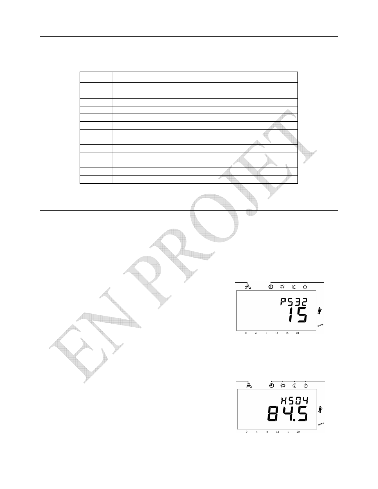
Burner operating cycle
To view the burner cycle, press the information sign 3 times
Code Explanation
0 Boiler at rest (no load)
1 Start up has failed
2 Burner fan starts up
3 Air purge
4 End of pre-ventilation period
5 Ignition
6 Flame established
10 Space heating established
11 Domestic hot water established
12 Both space heating & domestic hot water established
20 End of cycle
22 Position 0
99 Lock-out condition
4.6. Adjust the Settings
The obtain the best operation of the boiler,
the parameters must be adjusted by the commissioning engineer
or the installer, but must not be available to the owner.
The boiler has a parameter - P plus three numbers - which is exhibited
by touching one vertical arrow or the other, then saved by touching the vertical .
the vertical arrow once more
.
For a routine service engineer, the vertical arrows should be pressed
together to open up the programme and similarly closed - when the
P number becomes an H number
Page 29
page 30/41
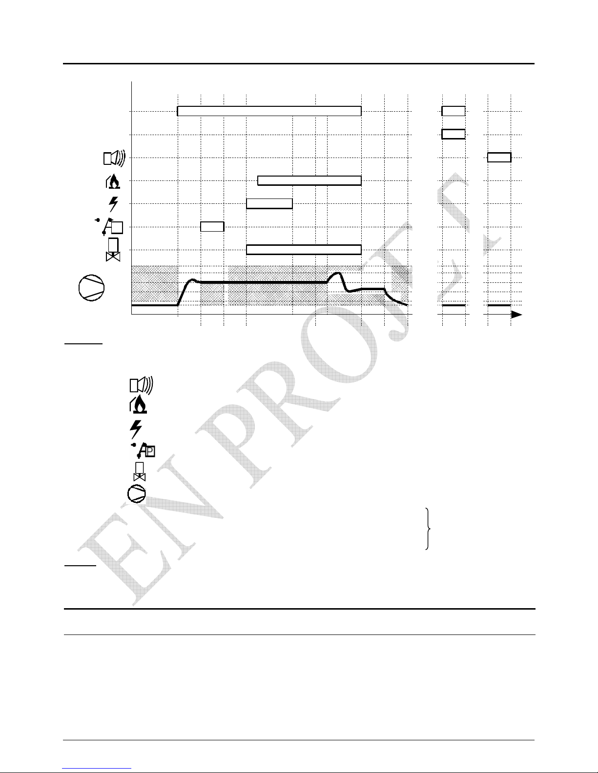
5. Function of the LMU64 060D168 Controller
Légende :
WDPS = water differential pressure switch, WPS = water pressure switch
LS = limit thermostat
= Alarm
= Flame established
= Ignition electrode
= Air pressure switch
= gas valve
= Burner fan
N maxi = maximum speed allowed.
N ignition = speed at ignition.
N mini = minimum speed allowed during modulation
N stop = speed less than 200rpm
NOTE : Should ignition fail at start up, the LMU will initiate 1 to 4 further attempts before going to lock-out
speed of burner fan
0 2 3 4, 5 6 10, 11, 12 20 22 1 99
VStart air purge. pilot control box Modul ation continuous return to Lock-out lock-out
purge periode ignition checks run start at start
N maxi
N ignition
N mini
N stop
5 s. 4,8 s. 10 s. t
Phase
CD, TL
Heat demand
P
0 s.
11 s.
WDPS, WPS, LS
6. Commissioning
6.1. Check all preparatory conditions
With a cascade system, check for equal flow
through all the boilers.
Check that there is a minimum water pressure 1 BAR
on each boiler.
With a V F replacement boiler, checked that
the existing system is flushed and clean
Page 30
page 31/41
6.2. Adjustment of the gas pressure
The VF gas train is correctly set at the Factory any adjustment
should be made only by an ATLANTIC commissioning engineer
.
Burner air/gas ratio
The gas valve is adjusted by setting up maximum and minimum boiler output.
Read chapter 4.3 on how to obtain these settings. To proceed with this, first set the gas
pressure before the gas valve at 20mBAR.
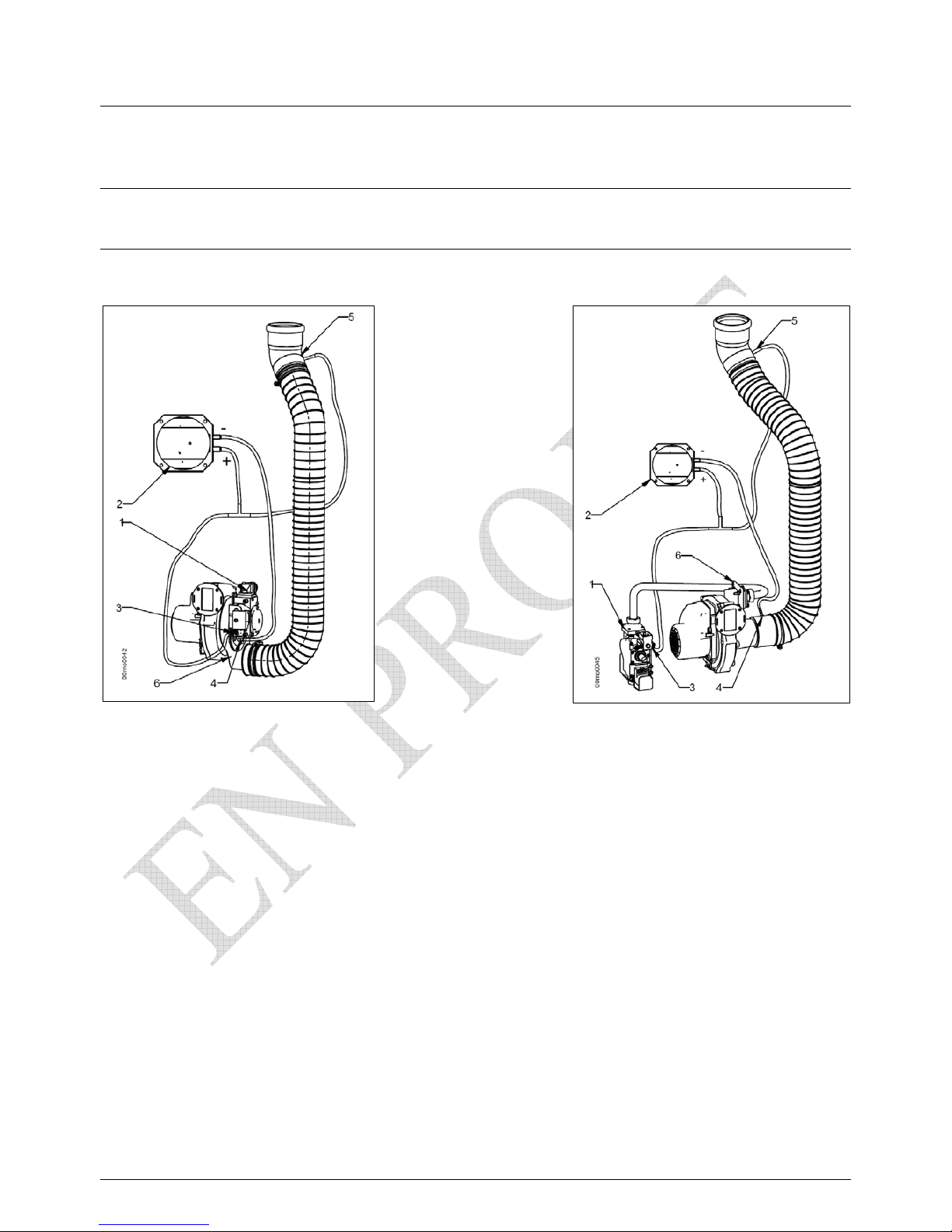
VF 60
VF 100
1 – gas valve
2 – differential air pressure
switch
3 – air tapping on valve
4 – air tapping on blender
5 – air tapping on bend
6 - blend
P2
P1
P2
P1
Page 31
page 32/41
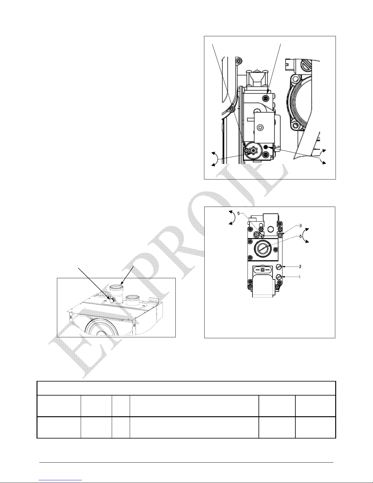
- Setting up a replacement gas valve
Before starting up the burner, adjust
the gas valve screw as the table below
- S tart the burner at maximum output
Using an analyser, measure the %CO2
Adjust the gas valve screw to a setting within the table below
- A djust the burner to minimum output
And repeat the exercise as described above
- Return to maximum and minimum settings
In turn, until the positions are stabilised
Return the boiler to normal setting
VF
gas
valve
Gas
Adjustment to regulator
CO2
Pmax
CO
2
Pmin
60
GB-WND
055
D01 S20
G20 Screw R1 1.5 turn clockwise 8,7 - 8,9 8,4 - 8,6
100
SIT 822
Novamix
G20 Screw R1 1.5 turns anti-clockwise 8,7 - 8,9 8,4 - 8,6
1 – upstream gas tapping
2 – mid stream gas tapping
3 – air tapping
5 – gas screw adjustment R1
6 – air screw adjustment R2
VF 100
+
R1
+
R2
-
VF 60
air tapping gas tapping
gas screw adjustment
R1
+
R2
+
air screw adjustment
tapping to measure %CO2
flue gas outlet
Page 32
page 33/41
6.3. Commissioning
Check the following
1. The boiler fitted with an electrical main isolator
2. The boiler has independent comfort control which
the Client can adjust
3. The gas line is sound
4. The boiler has been adjusted at maximum & minimum output
5. The flue gases have been analysed for optimum efficiency at both outputs
7. Checks after Commissioning
7.1. Check for correct draining of condensate
Look for any obstructions within the boiler, or in the drainage system
7.2. Check for correct flow of gas
Check the gas line size against boiler input and length of run
Check the gas pressure to each boiler, with different combinations of boilers
8. Maintenance Operations
All maintenance must be carried out by a qualified engineer
Before starting maintenance work
1. The boiler must be electrically isolated
2. The boiler gas supply valve must be closed
3. The boiler must be isolated from the heating system
Cleaning of the main heat exchanger
Check build up of residue on the tubes
If needed, clean the tubes with a non metallique brush
Ignition and ionisation electrodes
Check the geometry of both electrodes, and ignition spark gap
If needed, replace the electrodes
Condensate drainage siphon
Clean the siphon and check the drainage run for clearanc
Check the controller switching actions; water pressure differential, gas pressure, air pressure differential
Check the combustion efficiencies
Page 33
page 34/41
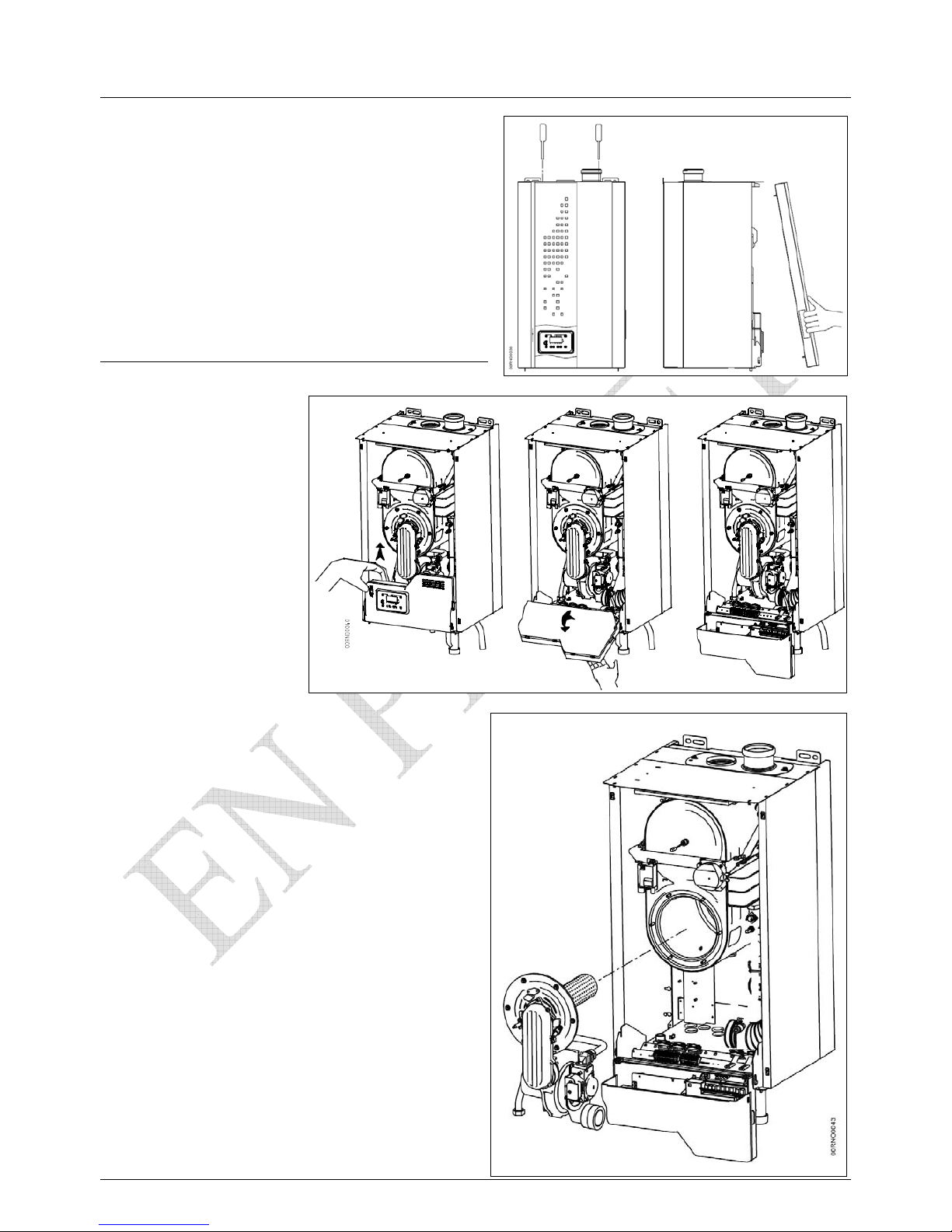
8.1. Annual maintenance
• Turn off the electrical supply
• Close off the gas supply
• Remove the front cover off the boiler
unclip the inner cover
• swing the controller forward
• Cover the controller connections against water ingress
• Undo the gas line, the combustion air tube and the
air micro-tubes from the burner
• Disconnect the electrodes, the fan and the
gas valve
• Remove the remaining burner assembly and
place it in a clean area
•
• T he combustion chamber is revealed
any residue should be cleaned with a non metallic
brush, by compressed air or a vacuum
cleaner
Acid or alkali should not be used
• If the refractory gaskets on the burner or the face
of the combustion chamber are damaged,
then they should replaced immediately.
•
•
VF 60
c
d
Page 34
page 35/41
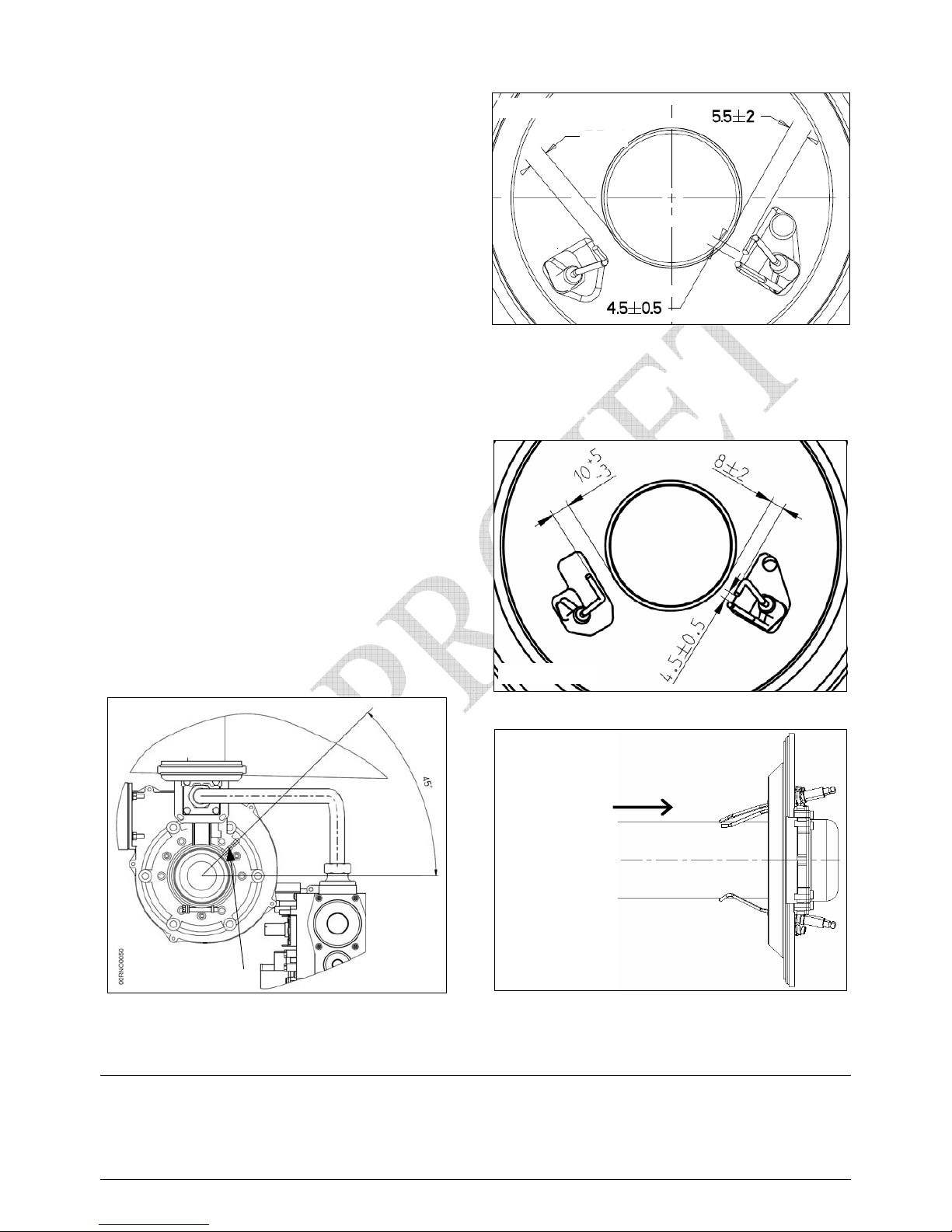
• If the burner head is damaged,
it should be replaced
• The electrode aluminium heads or ceramic
bases are damaged, they should be replaced
• Replace the burner in the position shown on
the drawings alongside
• Re-connect gas, air and micro-tubes
• Re-house the controller
• Switch on the electrical supply
• B ring the boiler into action, checking the
burner operation and combustion efficiencies
• Replace the front cover of the boiler
•
•
•
8.2. Draining the boiler
• Close the heating flow and return valves
• Open the safety valve to release the pressure
• Release the automatic air vent
• Connect a hose pipe to the drain valve and drain the boiler contents
Position of the air tapping on the pressure
diaphragm (VF 100 )
location of burner electrodes VF 100
view from F
VF burner
View from inside the combustion chamber
F
location of the burner electrodes
VF 60 Æ A = 5,5 +/- 2
view from F
A
Page 35
page 36/41
00RNO0036
1
2
1
2
3
4
5
6
8
9
10
11
12
13
14
15
16
17
7
19
22
37
28
20
30
29
27
39
23
18
24
21
26
25
38
32
31
34
33
35
20
40
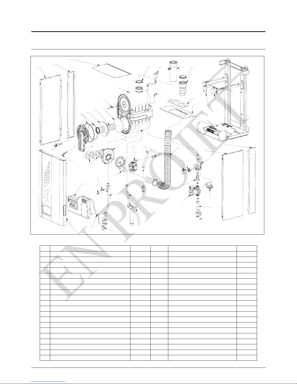
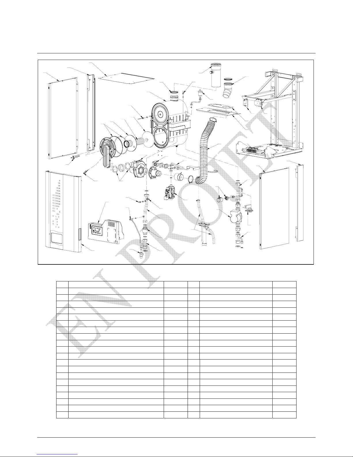
9. Spares lists
9.1. VF 60
N° D escription Code N° Description Code
1 left&right hand boiler panels 072 39
21 water differential pressure switch 072166
2 left&right joining panels 072849
22 automatic air vent 072164
3 front panel 072955
23 pressure return water pipe 072871
4 top panel 072881
24 non return valve 072167
5 rear panel 072852
25 suction return water pipe 072622
6
Support for air inlet bend 072882
26 heating circulator 072168
7 heat exchanger 072144
27 pressure flow water pipe 072872
8 ignition electrode 072146
28 limit thermostat 072169
9 ionisation electrode 072147
29 safety valve 072165
10 80mm flue outlet gasket 072148
30 drain valve 072171
11 burner refractory disk 072150
31 burner fan 072512
12 burner flame tube 072151
32 burner fan gaskets 072145
13 burner rear refractory disk 072152
33+34 gas valve assembly 072874
14 burner door refractory disk 072153
35 gas inlet tube 072883
15 boiler controller 072857 37 air inlet bend 072867
16 ignition transformer 072131
38 flexible air tube 072868
17 air differential pressure switch 072573
39 condensate siphon assembly 072875
18 water pressure switch 072300
40 flue gas outlet 072876
19 flue gas temperature sensor 072158
20 flow/return water temperature sensor 072859
Page 36
page 37/41
00RNO0037
1
1
3
4
5
6
7
8
9
10
11
12
13
14
15
16
17
18
19
20
20
21
22
24
25
40
27
28
29
30
26
32
33
34
35
37
39
38
41
31
23
2
2
9.2. VF 100
N° D escription Code N° Description Code
1 left&right hand boiler panels 072502
21 water differential pressure switch 072166
2 left&right joining panels 072849
22 automatic air vent 072164
3 front panel 072955
23 pressure return water pipe 072860
4 top panel 072851
24 non return valve 072509
5 rear panel 072852
25 suction return water pipe 072625
6 support for air inlet 072853
26 heating circulator 072510
7 heat exchanger 072854
27 pressure flow water pipe 072627
8 ignition electrode 072505
28 limit thermostat 072169
9 ionisation electrode 072856
29 safety valve 072165
10 100mm flue outlet gasket 072519
30 drain valve 072171
11 burner refractory disk 072517
31 burner fan 072862
12 burner flame tube 072941
32 burner fan gasket 072145
13 burner rear refractory disk 072152
33 gas valve assembly 072863
14 burner door refractory disk 072153
34 air/gas blender 072864
15 boiler controller 072858
35 gas inlet tube 072938
16 ignition transformer 072131
37 air inlet bend 072867
17 air differential pressure switch 072573
38 flexible air tube 072865
18 water pressure switch 072300
39 condensate siphon assembly 072869
19 flue gas temperature sensor 072158
40 flue gas outlet 072870
20 flow/return water temperature sensor 072859
41 condensate drain 072861
Page 37
page 38/41
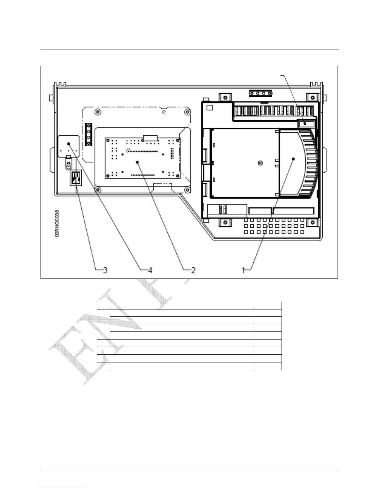
9.3. VF control panel
N° D escription Code
boiler controller LMU 64 VARFREE 60 072877
1
boiler controller LMU 64 VARFREE 100 072878
2
Interface HMI 060430
3 on/off switch 070385
4 CEM filter 071487
5 T6.3H fuse 071898
5
Page 38
0RNOxxxx-#_TR Installation Entretien VARFREE page 39/41
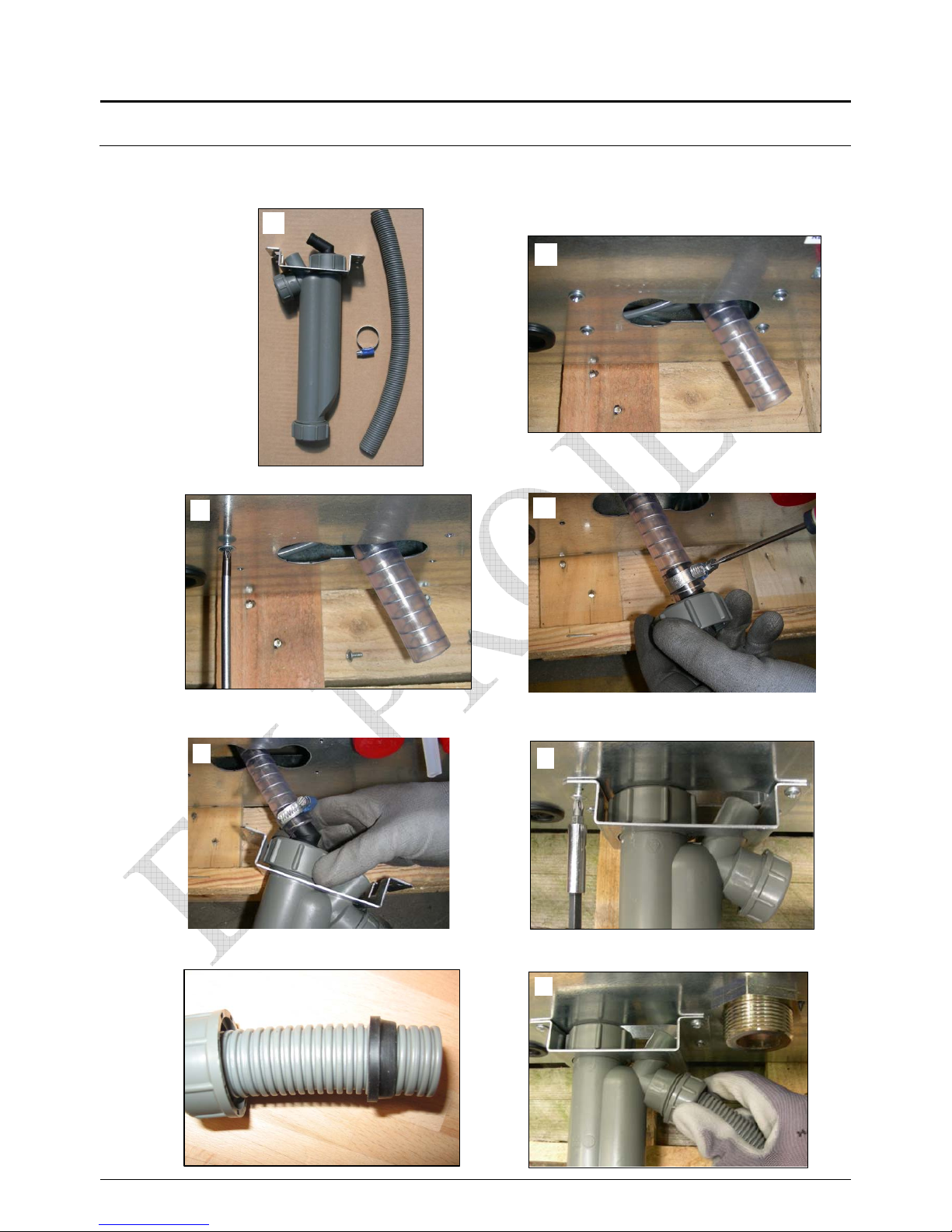
11. Installation of Condensate Siphon
The components of the siphon assembly will be found in a plastic container placed within
the boiler casing.
j
i
d
e
h
c
f
g
Page 39
0RNOxxxx-#_TR Installation Entretien VARFREE page 40/41
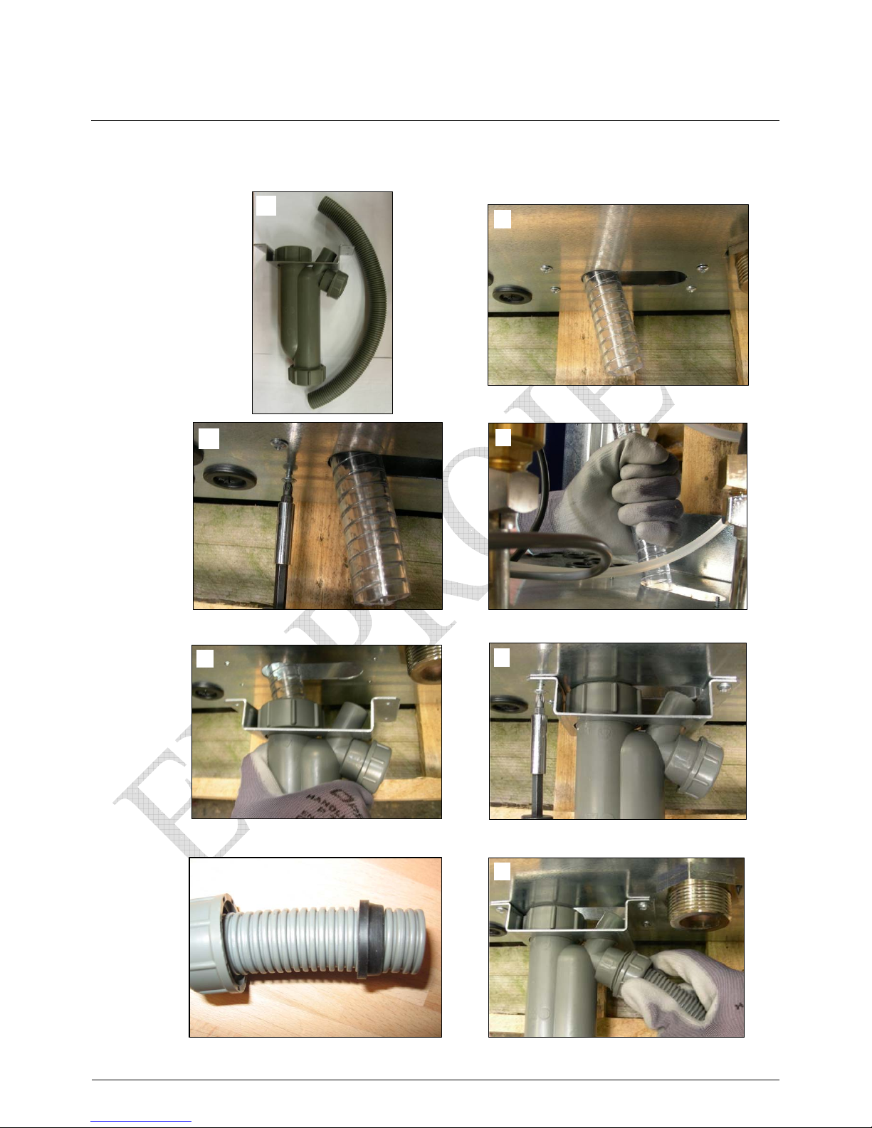
11.2. Installation of Condensate Siphon at VF 100
c
d
e
f
g
h
i
j
Page 40
page 41/41
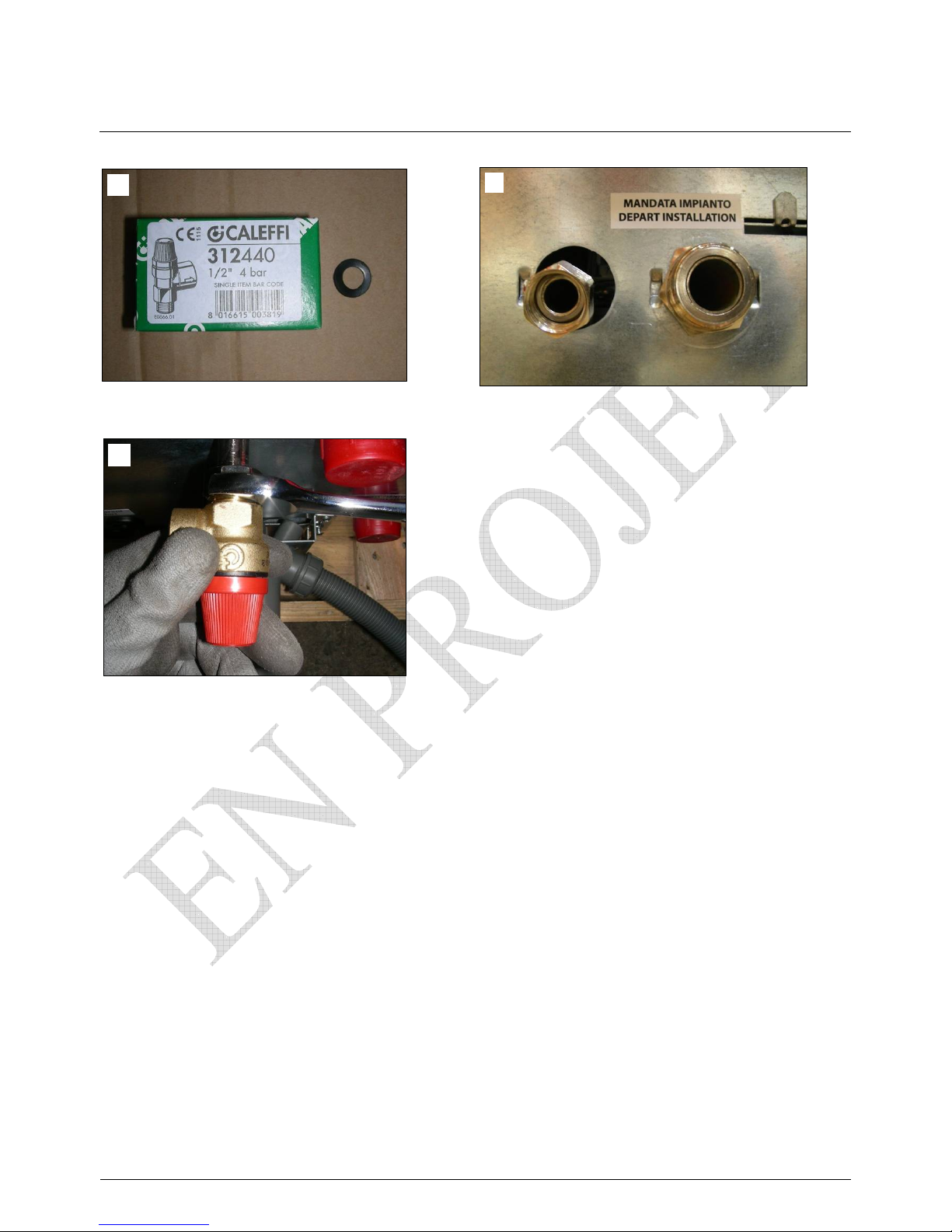
11.3. Installation of the safety valve at the VF boiler
c
d
e
 Loading...