

Page 1
TATOU DIGITAL
PANNEAU RAYONNANT VERSIONS HORIZONTALES ET VERTICALES
Radiant panel heater - Horizontal and vertical
Warmtestraalradiator - Horizontale en verticale modellen
Emisor radiante - Versiones horizontales y verticales
Emissor radiante - Versões horizontais e verticais
Promiennik elektryczny - wersja POZIOMA i PIONOWA
F
SP
NL
PL
GB
P
RU
NOTICE D’UTILISATION ET D’INSTALLATION
Installation and operating manual - Gebruiks- en installatiehandleiding - Manual de utilización e instalación - Manual do Usuario
e da Instalação - Instrukcja obsługi i monta
ż
u -
GUIDE À CONSERVER
PAR L’UTILISATEUR
Manual must be kept by end user
Gids te bewaren door de gebruiker
Guía que deberá ser conservada por el usuario
Guia a conservar pelo usuario
Page 2

27
Contents
Warning...........................................................................................................................................28
Installation
Preparing the installation of the device........................................................................................29
Unlocking the device’s hanging frame...........................................................................................30
Fixing the hanging frame to the wall.............................................................................................30
Connecting the device......................................................................................................................31
Locking the device on the hanging frame....................................................................................32
Operation.......................................................................................................................................33
Use
Turning on your device ....................................................................................................................34
Putting your device in standby mode ..........................................................................................34
Choosing your heating mode ........................................................................................................35
Heating your room: how to use Comfort mode .....................................................................36
Lowering the temperature of your room: how to use Eco mode ........................................37
Programming the heating period: how to use Programming mode ...........................38 to 42
Absence of more than 24 hours: use the Frost Protection mode .......................................43
How to use the energy-saving functions ..........................................................................44 to 48
Locking the controls.........................................................................................................................49
Locking the control panel ..............................................................................................................49
Calibrate the temperature..............................................................................................................50
Maintenance .......................................................................................................................................50
Returning to the standard factory settings .................................................................................50
Troubleshooting.................................................................................................................................51
Warranty conditions.........................................................................................................................53
GB
Page 3
28
The device you have just purchased was submitted to many tests and checks ensuring its quality.
We thank you for your choice ant trust. We hope you will be fully satisfied.
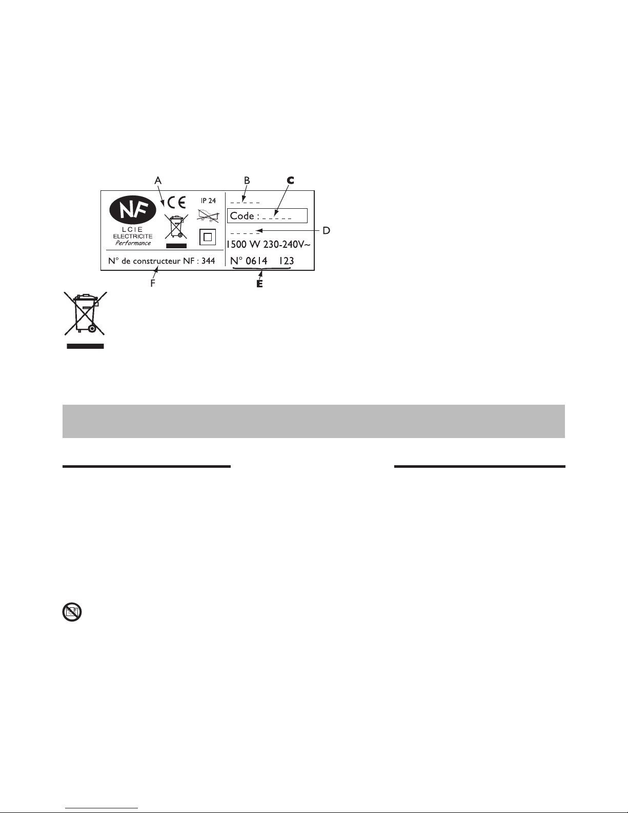
The references for your device
These are located on the right-hand side of the device.
The commercial code and the serial number identify for the manufacturer the particular device you
have bought.
Devices with this symbol must not be scrapped with normal household rubbish but be collected separately and recycled.
When these products come to the end of their useful life, they must be collected and recycled in accordance with the local regulations and bylaws.
- Please ensure that children do not lean on the device or play close to it when it is operating : its
surface may be hot enough to cause burns to their skin in some circumstances, particularly because their reflexes may not yet have been acquired or aur slower than those of an adult. If there is any
risk, fit a protective grill in front of the device.
-
This device is not intended for use by persons (including children) with physical, sensory or mental
disability, or by persons lacking experience or knowledge, unless they have received from a person
in charge of their safety adequate supervision or preliminary instructions on how to use the device.
- Care must be taken at all times to keep children from playing with the device.
- Do not obstruct the grills, even partially (either on the front of the device or underneath it): otherwise the device may overheat.
- If the supply cord is damaged, it must be replaced by a service agentor similarly qualified person in
order to avoid a hazard (applies to units fitted with a supply cord and plug).
- Units fitted with a three core supply cord (brown, blue and black), must be directly connected to hard
wiring by a licensed electrician.
- All work on the interior of the device must be carried out by a licensed electrician.
A
Standards, quality labels
B
Commercial name
C
Commercial code
D
Manufacturing reference
E
Serial number
F
Manufacturer’s number
Please keep this instruction manual even after installing your device.
Warning
Page 4

29
We strongly advise against installing vertical machines above an altitude of 1000m
(risk of faulty operation).
Installing a machine at altitude causes an increase in air output temperature
(of the order of 10°C per 1000m above sea level).
It is forbidden to install a vertical machine horizontally or vice versa.
Do not use the device in mobile, on feets or on casters.
Installation
Installation guidelines
- This device was designed to be installed in residential premises. In any other case, please call your
distributor.
- Installation must comply with the standards currently enforced in the country of use.
- The device must be supplied with 230V single-phase 50Hz.
-
In damp areas such as bathrooms and kitchens, you must install the connection box at least 25cm above
the floor.
Keep the device away from any draughts that may interfere with its operation (e .g.:
under a centrally controlled fan, etc...).
Do not install the heater under a fixed socket.
The device is fitted with a detection system, whose sensor is located on the front of the device.
PREPARING THE INSTALLATION OF THE DEVICE
50 cm
15 cm
Comply with the minimum distances from
any furniture units when positioning the
device.
To optimise absence detection by your device, do not
install it in a closed off corner or behind furniture.
Volume 1 No electrical device
Volume 2 Class II IPX24 electrical device
Volume 3 Class II electrical device
GB
Page 5
30
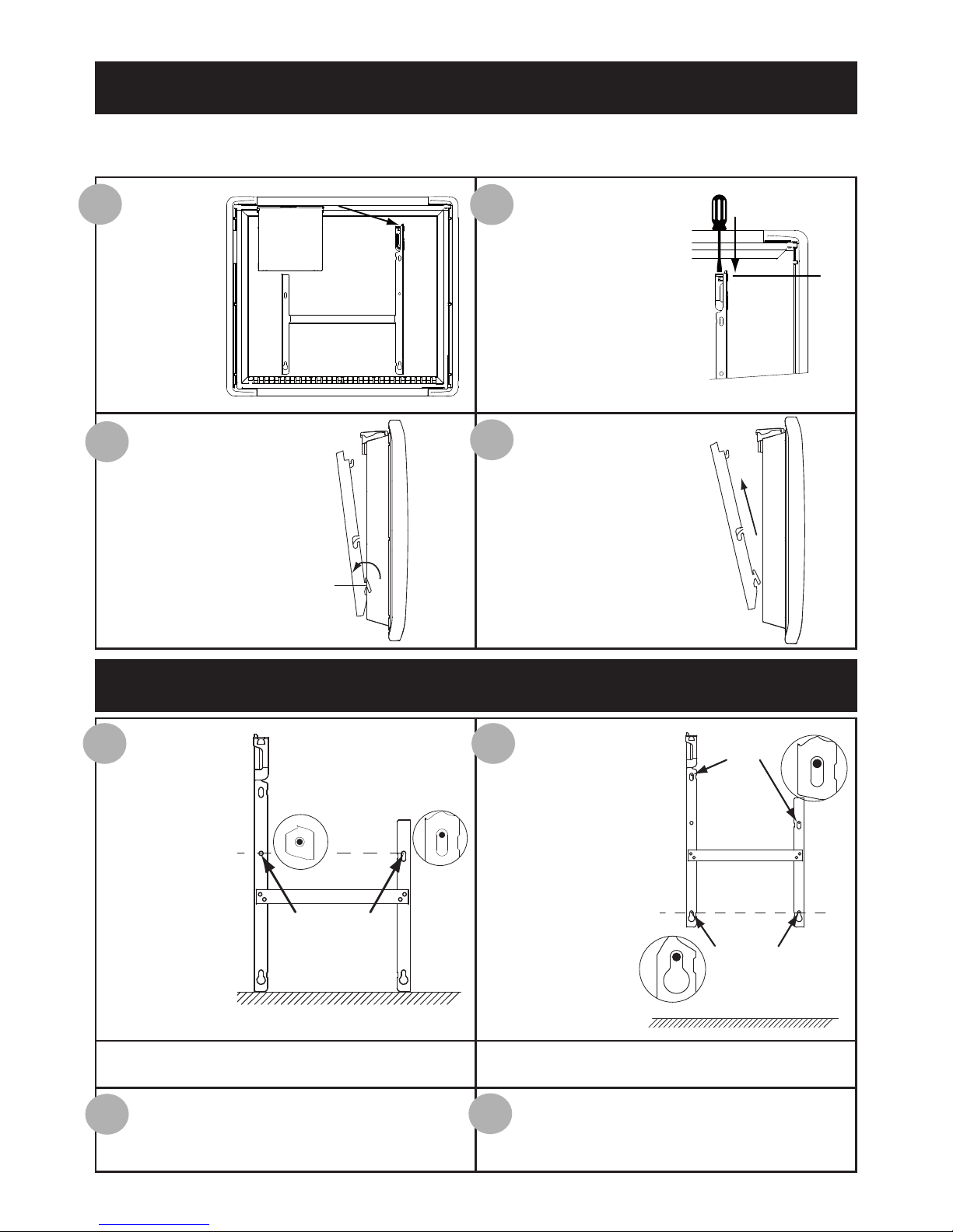
We recommend that you place the device face down on the floor, taking care to protect its front
surface from scratches.
UNLOCKING THE DEVICE’S HANGING FRAME
FIXING THE HANGING FRAME TO THE WALL
Take a flat-
bladed screwdriver and lift
the slider, taking
care not to
bend it.
While keeping the slider
raised, push the hanging
frame towards the bottom
of the heater to release the
upper brackets S2. We recommend that you wear
protective gloves.
Swivel the hanging
frame downwards on
the lower brackets S1.
Remove the hanging
frame.
S
2
S1
1
2
3
4
Place the hanging
frame on the
floor against the
wall. Locate
drilling points A.
Refit the hanging
frame, lining up with
drilling points A to
find drilling points B
(you can also use a
level).
Drilling points A show the position for the lower fastenings.
Drilling points B show the position for the upper fastenings.
Drill the 4 holes and insert the wall plugs.
Use suitable wall plugs when fitting on a
specific support (e.g. plasterboard wall).
Position the hanging frame and screw it
down.
1 2
3
4
Drilling
points A
Drilling
points A
Drilling
points B
Page 6
31
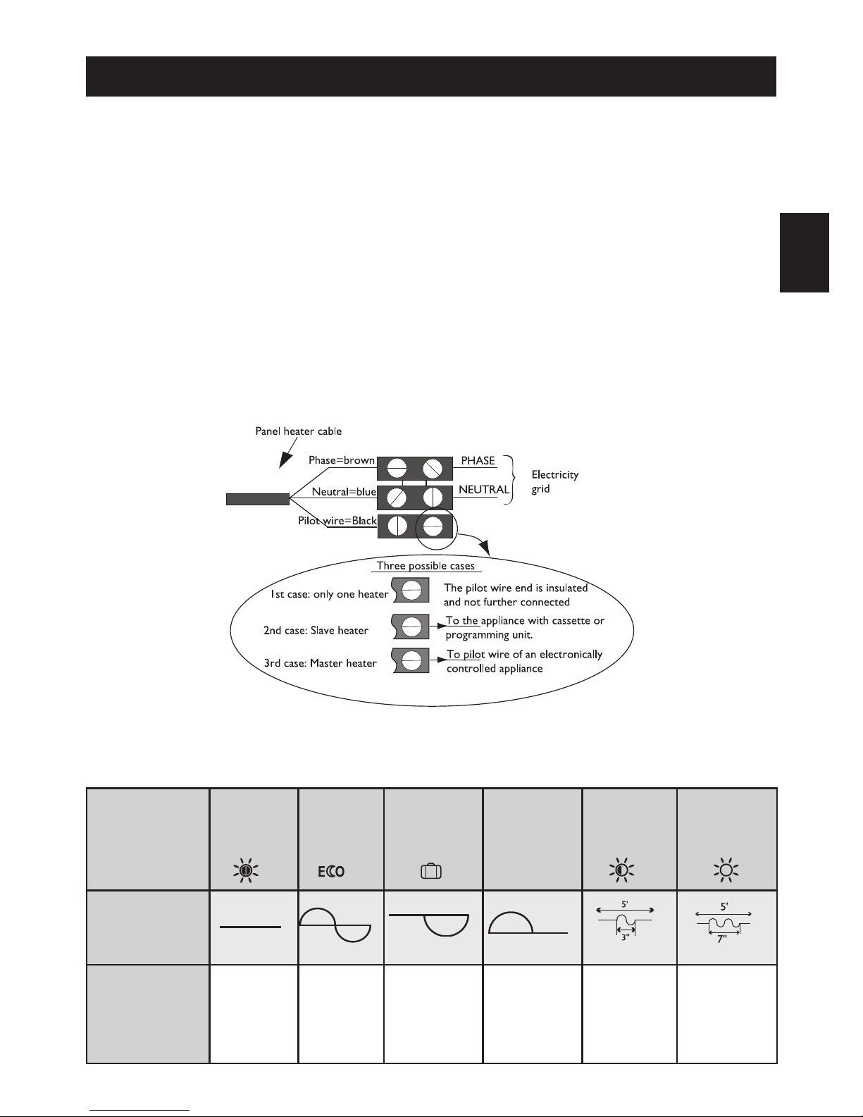
Wiring diagram for the heating panel
-
Cut off the power supply and connect the wires as shown in the following diagram:
- You can connect the pilot wire if your home is equipped with a programming unit or controller.
In this case, make the following checks according the selected mode (Comfort, Eco, etc.) to that the
programming instructions are being transmitted correctly:
COMFORT ECO FROST
SWITCH-OFF
OF HEATING
AND POWER
CUT-OFF
COMFORT
-1°C
COMFORT
-2°C
SIGNAL TO BE
TRANSMITTED
MEASUREMENT
BETWEEN THE
PILOT WIRE
AND NEUTRAL
0 Volt 230 Volts
-115 Volts
negative
+115 Volts
positive
230 Volts
for 3 s
230 volts
for 7 s
CONNECTING THE DEVICE
Connection rules and regulations
- The device must be supplied with 230V single-phase current at 50Hz.
- The device’s power supply must be directly connected to the main supply after the circuit breaker
without any intermediate switch.
- The device’s power cable must be connected to the main supply via a connection box. In damp areas,
such as bathrooms and kitchens, the connection box must be installed at least 25cm above the floor.
- An Earth connection is prohibited. Do not connect the pilot wire (black wire) to Earth.
- The installation must be fitted with an all-pole cut-off switch with a contact opening distance of at least
3mm.
- If the power cable is damaged, it must only be replaced by an electrician.
- If you are using the pilot wire and it is protected by a 30mA differential (e.g.: bathroom use), the pilot
wire’s power supply must also be protected on this differential.
GB
Page 7
32
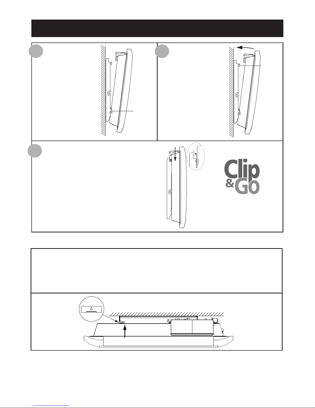
LOCKING THE DEVICE ONTO THE HANGING FRAME
Position the tilted
device on brackets
S1.
Pivot the device
upwards and lift it to
position it on brackets S2.
Lower the device onto the hanging frame. A
click tells you that the device is fastened and
locked in place.
1
2
3
S1
S2
CLIC
To unlock the device from the hanging frame, take a flat-bladed screwdriver and push the
slider (located on the top left-hand corner of the hanging frame behind the device) towards
the wall.
Lift the device while holding the slider in place with your screwdriver. Tilt it for-
wards and then remove it from brackets S1.
Page 8
33
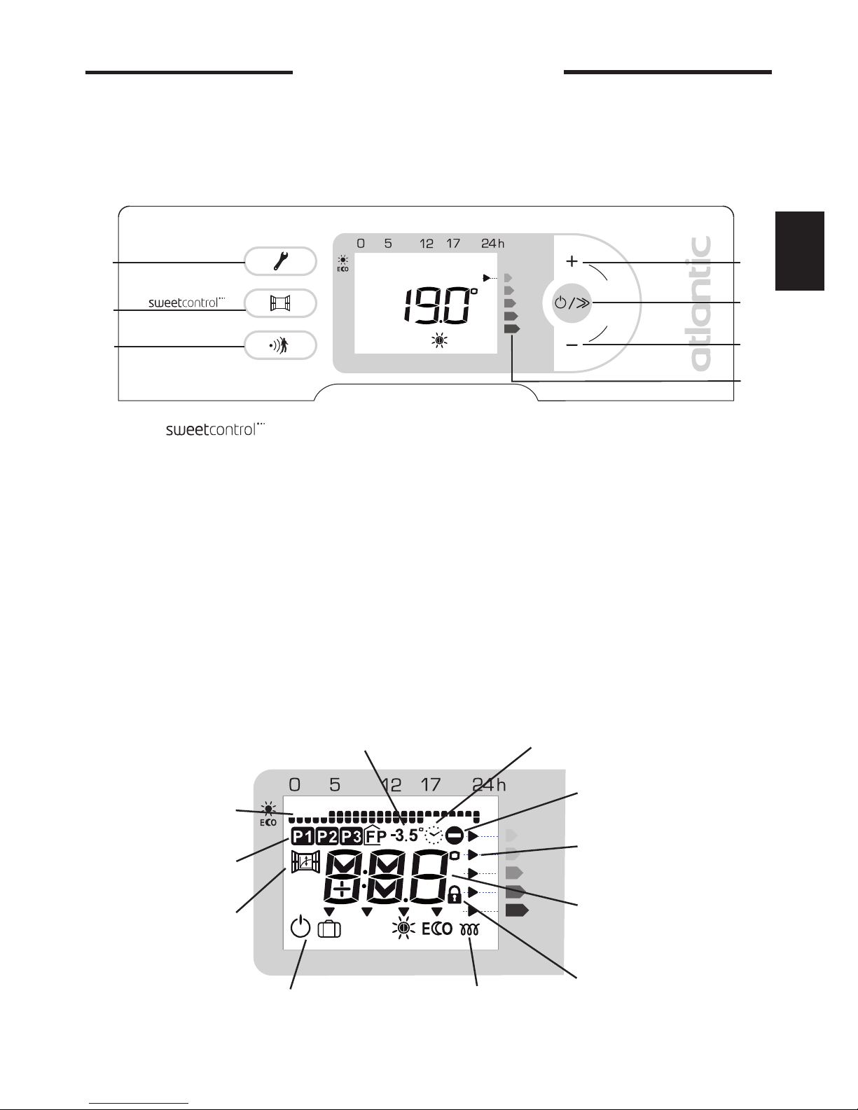
A
absence and presence detector
B
Airing function
C
Programming / Ste the correct time and day
D
Increase the temperature / Scroll
E
Turn on / Change heating modes – scroll / Standby
F
Lower the temperature / Scroll
G
Consumption indicator function
Operation
Control box
The different displays
Remove the plastic film on the control unit
For your comfort and to save energy, your device is equipped with a digital-display control unit. You
can set all of the device’s functions from the unit.
After 2 minutes of inactivity, the screen returns to the main display.
é
q
u
i
l
i
b
r
e
A
B
C
D
E
F
G
PROG
Prog
ra
m displa
y
ed
Prog
ra
m selection
Airin
g function
Advised Ec
o temperatu
r
e
Day a
n
d time
Ac
tion not possible
C
onsumption indicators
Temper
ature display
or day
a
nd time i
f bein
g
set
C
ont
rols locked
Heating indicator
Modes
GB
Page 9
34
Use
ACTIVATING THE SCREEN
If the screen is not lit up, press any button to activate the screen lighting.
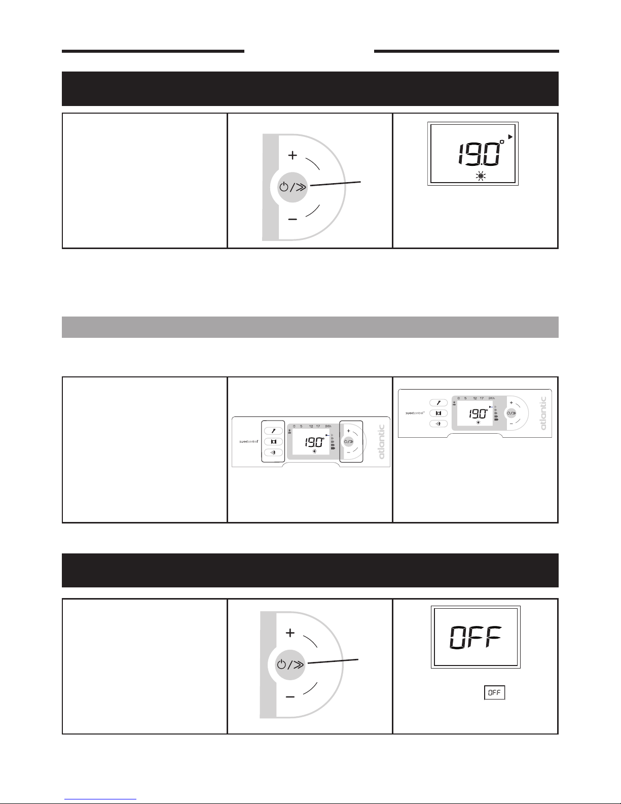
TURNING ON YOUR DEVICE
When first turned on, the device is set to Comfort mode at 19°C.
PUTTING YOUR DEVICE IN STANDBY MODE
To turn on your device, press the
Power on key (E).
The device displays the ‘comfort’
temperature.
If the screen backlighting is not
active, press any button to reactive it.
You can now press the appropriate button for the setting you
want to make.
To put your device in standby
mode, hold the Standby key (E)
down.
The panel displays then turns
off.
é
q
u
i
l
i
b
r
e
E
é
q
u
i
l
i
b
r
e
E
é
q
u
i
l
i
b
r
e
é
q
u
i
l
i
b
r
e
Page 10

35
CHOOSING YOUR HEATING MODE
You can run your device in several modes:
- Comfort mode ( ) which enables you to have the right ambient temperature.
- Eco mode ( ) which enables you to lower the temperature in your room when you will be away
from your home for a long time or during the night, especially in bedrooms.
- The Programming mode, where you can program the Comfort and Eco modes depending
on when the room is used, using programs P1, P2, P3 or using a (centralised) programming system.
- Frost mode ( ) which enables you to maintain a temperature of around 7°C during an absen-
ce of more than 24 hours, for example.
PROG
GB
Page 11

36
HEATING YOUR ROOM :
HOW TO USE COMFORT MODE
The advised Comfort temperature is 19°C.
The Comfort mode ranges from 12.5°C to 28°C.
This mode enables you to have the ambient temperature you desire in your room. The consumption
indicator lights enable you to optimise your setting (see page 48).
DESCRIPTION
HOW TO ACTIVATE THIS MODE ?
If the screen is not lit up, press any button to activate the screen lighting.
HOW TO CHANGE THE TEMPERATURE
Wait at least 6 hours for the room’s
temperature to stabilise.
To activate the Comfort mode,
press the Scroll key (E) several
times until the arrow is on the
Comfort mode.
The mode selection arrow flashes
for several seconds, then just the
icon remains on the display:
the setting is confirmed.
é
q
u
i
l
i
b
r
e
E
To change the temperature displayed, press the + (D) or – (F)
keys.
The heating icon appears on
the screen if the room temperature is lower than the one displayed.
é
q
u
i
l
i
b
r
e
D
F
PROG
If you want to change the room
temperature, change it by pressing the + (D) or – (F) keys.
As the temperature displayed on
the screen rises, the consumption
indicator light descends.
é
q
u
i
l
i
b
r
e
D
F
Page 12

37
LOWERING THE TEMPERATURE IN YOUR ROOM :
HOW TO USE ECO MODE
We recommend that you use this mode when you will be absent for 2 to 24 hours, or during the
night, especially in bedrooms.
Maximum Eco temperature is 19°C.
The advised Eco temperature is -3.5°C compared with the Comfort temperature (setting example: 19°C in Comfort
mode and 15.5°C in Eco mode). If the -3.5°C icon does not appear on the screen, this means that the difference
compared with the set Comfort temperature is not 3.5°C.
If you lower the Comfort temperature to below the Eco temperature, the Eco temperature lowers by -0.5°C compared with the Comfort mode If, however, you increase the Comfort temperature, the Eco temperature does not
change.
DESCRIPTION
HOW TO ACTIVATE THIS MODE ?
HOW TO CHANGE THE TEMPERATURE ?
GB
Press the scroll key (E) several
times until the selection arrow is
on mode.
The mode selection arrow flashes
for several seconds, then just the
icon remains on the display:
the setting is confirmed.
é
q
u
i
l
i
b
r
e
E
PROG
If you want, you can change the
temperature displayed by pressing the + (D) or – (F) keys.
The chosen Eco temperature
appears on the screen.
é
q
u
i
l
i
b
r
e
D
F
Page 13

38
You can program your Comfort and temperature times either by using one of the three
prestored programs, or by connecting the pilot wire to a programming control (Pilot wire (FP) mode
is the default setting - refer to your programming control’s manual)
You can connect several devices to one programmer.
3 programs have been prestored: , and and they cannot be changed.
is recommended for when you are constantly at home, at the weekend for example (Eco mode
from 23h to 5h, Comfort mode from 5h to 23h).
is recommended if you are absent during the day (Eco mode from 23h to 5h and from 9h to 17h,
Comfort mode from 5h to 9h and from 17h to 23h).
is recommended if you are absent during the day, but you come back home at lunchtime (Eco
mode from 23h to 5h, from 9h to 12h and from 14h to 17h, Comfort mode from 5h to 9h, from
12h to 14h and from 17h to 23h).
means that a programming control is used.
PROGRAMMING THE HEATING PERIOD :
HOW TO USE PROG MODE
PROG
0h 1h 2h 3h 4h 5h 6h 7h 8h 9h
10h 11h 12h 13h 14h 15h 16h 17h 18h 19h 20h 21h 22h 23h
NB : If no command is received on the pilot wire, the device will function in Comfort mode.
When switching from Comfort to Eco mode, the new mode is active after about 12 seconds.
The Frost Protection and Load shedding commands have priority over the Eco, Comfort and programming (P1, P2, P3 and ) modes.
Page 14

39
HOW TO SET THE DAY OF THE WEEK AND TIME ?
Before programming the device, you must set the device to the correct time or make sure that the
system day and time is correct.
GB
To set the day of the week and
the time, hold the Programming
key (C) down for several seconds.
The letters on the screen start
flashing: you can now set the day
of the week.
(J= day - LU = Monday)
C
To change the hour, press the +
(D) or - (F) key.
You have changed the hour. You
can now set the minutes.
é
q
u
i
l
i
b
r
e
D
F
To set the time, press the Scroll
(E) key.
The letters on the screen flash
so that you can change the hour.
é
q
u
i
l
i
b
r
e
E
To change the day, press the +
(D) or - (F) key.
You have changed the day. You
can now set the time.
é
q
u
i
l
i
b
r
e
D
F
Page 15

40
N.B.: You can exit the settings at any time by pressing the Programming key (C).
The settings made are saved.
To change the minutes, press the
+ (D) or - (F) key.
You can now confirm your setting.
é
q
u
i
l
i
b
r
e
D
F
To set the minutes, press the
Scroll (E) key.
The letters on the screen flash
so that you can change the minutes.
é
q
u
i
l
i
b
r
e
E
To confirm the minutes, press
the Scroll (E) key.
The screen returns to the main
menu.
é
q
u
i
l
i
b
r
e
E
Page 16

41
HOW TO ASSIGN A DAILY PROGRAM ?
a- You want to keep the selected program – Monday in the example
b-You want to change the selected program – Monday in the example
Two solutions are possible :
a- you want to keep the selected program,
b- you want to change the selected program.
GB
To access the daily program,
press the Programming key (C).
For Monday, the ‘FP’ program is
selected.
(J= day - LU = Monday -
FP = programming control)
C
You want to keep the ‘FP’ program for Monday: press the
Scroll key (E).
The program for Monday is confirmed. You can now select the
program for Tuesday.
é
q
u
i
l
i
b
r
e
E
You want to change the ‘FP’ program for Monday: press the +
(D) or - (F) key until the program you want flashes on the
screen.
You have chosen the P3 program
for Monday, you can now confirm.
é
q
u
i
l
i
b
r
e
D
F
Page 17

42
HOW TO ASSIGN A DAILY PROGRAM TO ALL THE DAYS OF THE WEEK ?
Carry out the same procedure for all the days of the week, up until Sunday, either keeping the selected program or changing it.
N.B.: Even if there is a power cut, the settings are saved.
HOW TO ACTIVATE THE PROGRAMMING MODE ?
PROG
N.B.: If the icon blinks, you need to check the day and time settings (see page 39).
Confirm the programs chosen
for each day of the week by
pressing the Scroll key (E).
You have confirmed the daily
programs. You must now activate
the Programming mode.
é
q
u
i
l
i
b
r
e
E
To activate the Programming
mode, press the Scroll key (E)
until the arrow is on this mode
.
The mode selection arrow flashes
several seconds, then remains on
the display with the icon of
the mode being programmed.
é
q
u
i
l
i
b
r
e
E
PROG
PROG
PROG
PROG
Page 18

43
ABSENCE OF MORE THAN 24 HOURS:
USING THE FROST PROTECTION MODE
The Frost Protection temperature is preset to 7°C (±3° C) and cannot be changed.
HOW TO ACTIVATE THE FROST PROTECTION MODE ?
GB
Press the scroll key (E) until the
selection arrow is on the Frost
Protection mode.
The mode selection arrow flashes for several seconds then the
icon remains on the display.
é
q
u
i
l
i
b
r
e
E
PROG
Page 19

44
The function enables you to lower the temperature setting for your room automatically, as soon as
you leave it.
HOW TO USE THE ENERGY-SAVING FUNCTIONS :
ABSENCE AND PRESENCE DETECTION
These functions enable your device to adapt itself to your daily life without your having to concern
yourself with it.
To use these functions, we recommend that you set the Comfort mode or Programming
mode.
These functions are in addition to the programming functions.
PROG
Absence detection is made from a height of over 45cm (Diagram 1) and operates progressively (Diagram 2):
12 cm
45 cm
20°
5 m
environ
Diagram 1
Diagram 2
E.g.: Your device is set to 19°C, in Comfort mode (whether programmed or not)
At 9:00, it detects your absence.
At 9: 30, its operating instructions are set to18°C.
At 10:00, its operating instructions switch to 17°C.
Page 20

45
If your device detects no one in the room, it automatically lowers the temperature setting progressively to 3.5°C lower than the Comfort temperature setting.
The symbol flashes when it detects a presence.
HOW TO ACTIVATE THE ABSENCE AND PRESENCE DETECTION ?
HOW TO DEACTIVATE THE ABSENCE AND PRESENCE DETECTION ?
GB
To activate it, press the
Sweetcontrol key (A).
The symbol for absence /
presence detection appears on
the screen.
A
To deactivate it, press the
Sweetcontrol key (A).
The symbol for absence /
presence detection disappears
from the screen.
A
Page 21

46
The function enables you to stop the device from heating and to start heating again automatically
when you are airing your room, thereby saving you energy.
We do not recommend the use of the Airing function in corridors and rooms located close to
an entrance door from outside your home or from the garage.
Do not heats the room while it is being ventilated allow you to save energy. If you do not turn off your
heater when a window is open for a long time, the airing function stops your device from heating
when it is not necessary: your heater automatically detects when the window is opened or closed and
therefore saves energy.
Your device reacts to an open or close window according to several variables, especially
- the temperature settings programmed for the room
- the outside temperature
- the location of your heater, etc.
By detecting whether the window is open or closed, the airing function helps you to be environmentally friendly: you save energy by not heating your house when you ventilated it.
Optimum zone
HOW TO USE THE ENERGY-SAVING FUNCTIONS :
AIRING FUNCTION
Page 22

47
The operating instructions are for 7°C ±3°C for the whole time that your room is being aired. When you
close the window, your device will return to its initial operating mode.
After 2 hours, the device starts heating again in any case. The maximum expected airing
period is 2 hours.
N
NB: If the function does not meet your requirements, you can manually stop the device from heating
(press the
Power on key (E) for several seconds).
The symbol flashes when it is lowering its operating set point.
HOW TO ACTIVATE THE WINDOW OPEN AND CLOSED DETECTION ?
HOW TO DEACTIVATE THE WINDOW OPEN AND CLOSED DETECTION ?
GB
To activate it, press the
Aeration key (B).
The symbol for absence /
presence detection appears on
the screen.
B
To deactivate it, press the
Aeration key (B).
The symbol for window
open and closed detection disappears from the screen.
B
Page 23

48
Use the Balance function to set your device at an optimum temperature that is just the right balance
between being comfortable and saving energy.
This function does not change how you have programmed your device.
HOW TO USE THE BALANCE FUNCTION ?
The energy consumed by an electrical heating device depends, among other things, on the temperature required. The temperature recommended by the public authorities is 19°C, in Comfort mode
(15.5°C in Eco mode).
The “Consumption Indicator” function enables you to position yourself in accordance with this
recommended temperature.
Therefore, depending on the temperature required:
- If the black arrow on the screen is placed before the 2nd orange or the red
icon, you can save energy by significantly lowering the temperature you have
asked for.
- If the black arrow on the screen is placed before the 1st orange icon, you can
save energy by slightly lowering the temperature you have asked for.
- If the black arrow is in front of the green icon, you are already at the recommended temperature and are already making energy savings.
All the devices in the same room must be fitted with the same function capabilities. The energy-saving functions must be set in the same way on each heater.
HOW TO USE THE ENERGY-SAVING FUNCTIONS :
CONSUMPTION INDICATOR
HOW TO USE THE ENERGY-SAVING FUNCTIONS :
THE BALANCE FUNCTION
To use this function, press the
Increase (D) and Decrease (F)
keys simultaneously.
The temperature displayed is
19°C in Comfort mode
and 15.5°C in mode.
é
q
u
i
l
i
b
r
e
D
F
Page 24

49
To avoid the control panel being used inopportunely, we advise you to lock it.
LOCKING THE CONTROLS
LOCKING THE CONTROL PANEL
You can also lock the control panel using the screw provided.
HOW TO LOCK THE CONTROLS ?
HOW TO UNLOCK THE CONTROLS ?
GB
To lock the controls, press the
following keys simultaneously for
several seconds:
- Aeration (B) and
- Power on (E).
A lock appears on the screen: the
settings can no longer be changed.
é
q
u
i
l
i
b
r
e
B
E
To unlock the controls, press the
following keys simultaneously for
several seconds:
- Aeration (B) and
- Power on (E).
The lock disappears from the
screen: the settings can be
changed.
Remove the screw located inside
the control panel.
Close the control panel’s flap.
Block the flap using the screw.
The panel can no longer be
opened, so the controls cannot be
accessed.
é
q
u
i
l
i
b
r
e
B
E
Page 25

51
PROBLEM
ENCOUNTERED
CHECKS TO BE MADE
The heating light flashes
The temperature probe is disconnected or is faulty.
Contact your installer.
The device does not
heat.
Make sure that the mode is activated.
If you are operating under programming, check that the programmer is in
COMFORT mode.
Ensure that the installation’s circuit breakers are engaged and
that the power cut-off (if you have one) has not cut off the power to the device.
Check the air temperature in the room: if it is too high, the heating light does
not flash : the device does not heat.
The device heats all
the time.
- Check that the device is not in a draught or that the temperature setting has
not been altered.
- There may be a fluctuation in the main power supply. If there is a problem
(blocked thermostat...), cut off the power to the device (fuse, circuit breaker) for
approximately 10 minutes and then switch it back on.
- If the phenomenon recurs frequently, have your electricity utility check the
power supply.
The device heats
even though the window is open.
There may be a delay between when the window is opened and when the
heating stops.
If you find this delay too long, you can manually stop your device.
The device does not
heat enough.
Increase the temperature settings by pressing the + (E) key.
If the setting is at its maximum, carry out the following checks :
- Check whether there is another heating device in the room.
- Make sure that your device is only heating the room (door closed).
- Check the supply voltage to the device.
- Check that the power of your device is adapted to the size of your room
(on average, we recommend 100 W/m² for a ceiling height of 2.50 m).
The heating light
appears on the
screen when the
device is in Eco
mode.
This is normal. The device can heat to maintain an Eco temperature.
Dirty marks appear
on the wall around
the device.
The dirty marks come from the bad quality of the air in the room. In this case,
you are advised to check that the room is correctly aired (ventilation, vent duct,
etc.), that the air is clean and not to smoke in the room. Your device will not
be replaced under guarantee because of these dirty marks.
TROUBLESHOOTING
GB
Page 26

52
PROBLEM
ENCOUNTERED
CHECKS TO BE MADE
The device’s surface
is very hot.
It is normal for the device to be hot when it is operating; the maximum surface temperature is restricted in accordance with the NF electrical performance standard. However, if you think that your device is still too hot, check
that the output is suitable for the area of your room (we recommend 100W /
m2) and that the heater is not placed in a draught, which would interfere with
its self-regulation; also check that the installation guidelines have been followed (curtains, etc.)
For devices equipped with a programming system or controlled via a pilot wire:
The device is not
responding to the
external programming commands.
Make sure that the central programming system is working correctly (refer to
the user manual), or that the programming control is correctly placed in its
holder and that it is working correctly (check the batteries, fuse, etc.)
Make sure that your device is in Programming mode and that the external
“Centralised” program is assigned to the right day of the week.
If you do not succeed in solving your problem, contact your local installer and have the
details of your device’s references (see page 28), the room’s temperature and the programming system (if any) to hand.
Page 27

53
- The guarantee period is two years from the date of installation or purchase and may not exceed 30
months from the date of manufacture in the absence of a receipt.
-The guarantee covers the replacement and supply of components recognised as being defective,
excluding any damages or interest.
- The user is responsible for any labour or transport costs.
- The guarantee does not cover any damage arising from improper installation, abnormal use or nonobservance of the requirements of the said instructions for installation and use .
- The stipulations of the present guarantee conditions do not exclude any of the purchaser’s legal
rights of guarantee against faults or hidden defects, which are applicable in all cases under the stipulations of Articles 1641 of the Civil Code.
- Present this certificate to your distributor or installer only in the event of a claim, together with
your purchase invoice.
TYPE OF DEVICE*: . . . . . . . . . . . . . . . . . . . . . . . . . . . . . . . . . . . . . . . . . . . . . . . . . . . .
SERIAL NUMBER*: . . . . . . . . . . . . . . . . . . . . . . . . . . . . . . . . . . . . . . . . . . . . . . . . . . . .
CUSTOMER’S NAME AND ADDRESS: . . . . . . . . . . . . . . . . . . . . . . . . . . . . . . . . . . . . . . . . . . . . . . . . . .
. . . . . . . . . . . . . . . . . . . . . . . . . . . . . . . . . . . . . . . . . . . . . . . . . . . .
* This information can be found on the information plate situated on the left-hand side of the device.
RYHG SEPT 12 12-80-1293-B
FOR SALES IN NEW ZEAL
ANDATLANTIC AUSTRALASIA - Phone :
0800 422 000 - Fax : 04 3800 509
ATLANTIC INTERNATIONAL
Tel: (33) 146836000
Fax: (33) 146836001
FOR SALES IN THE U.K.,
please contact :
ATOUR ATLANTIC LTD
Malling Works, Lewes
East Sussex BN7 2AY
Phone : 01580 2431 53
Fax : 01580 2411 80
E-mail : sales@tour-atlantic.ltd.uk
FOR SALES IN AUSTRALIA
ATLANTIC AUSTRALASIA PTY LTD
4/13-25 Church Street
Hawthom Victoria 3122
Australia
Free call : 1800 677 857
Phone : 03 9852 9599
Fax : 03 9852 9844
web : www.atlantics.com.au
INSTALLER’S STAMP
WARRANTY CONDITIONS
Page 28

GARANTIE
DOCUMENT À CONSERVER PAR L’UTILISATEUR,
À PRÉSENTER UNIQUEMENT EN CAS DE RÉCLAMATION
La durée de garantie est de 2 ans à compter de la date d’installation ou d’achat et ne saurait excéder
30 mois à partir de la date de fabrication en l’absence de justificatif.
Atlantic assure l’échange ou la fourniture des pièces reconnues défectueuses à l’exclusion de tous
dommages et intérêts.
Les frais de main d’œuvre, de déplacement et de transport sont à la charge de l’usager.
Les détériorations provenant d’une installation non conforme, d’un réseau d’alimentation ne respectant
pas la norme NF EN 50160, d’un usage anormal ou du non respect des prescriptions de ladite notice ne
sont pas couvertes par la garantie.
Les dispositions des présentes conditions de garantie ne sont pas exclusives du bénéfice, au profit de
l’acheteur, de la garantie légale pour défauts et vices cachés qui s’applique en tout état de cause dans
les conditions des articles 1641 et suivants du code civil.
Présenter le présent certificat uniquement en cas de réclamation auprès du distributeur ou de votre
installateur, en y joignant votre facture d’achat.
SATC
Rue Monge - ZI Nord
85002 LA ROCHE SUR YON Cedex
* Ces renseignements se trouvent sur la plaque signalétique, côté gauche de l’appareil.
TYPE DE L’APPAREIL* : ...............................................................................................
N° DE SÉRIE* : .............................................................................................................
NOM ET ADRESSE DU CLIENT : ..................................................................................
.....................................................................................................................................
Cachet du distributeur
www.atlantic.fr
Edition 2011
Tous les litiges relèvent de la compétence exclusive
des tribunaux de la Roche-sur-Yon.
 Loading...