

Page 1
THIS INSTRUCTION BOOKLET CONTAINS
IMPORTANT SAFETY INFORMATION, PLEASE
READ AND KEEP FOR FUTURE REFERENCE.
Lot Number:
Date:
Item #36835516
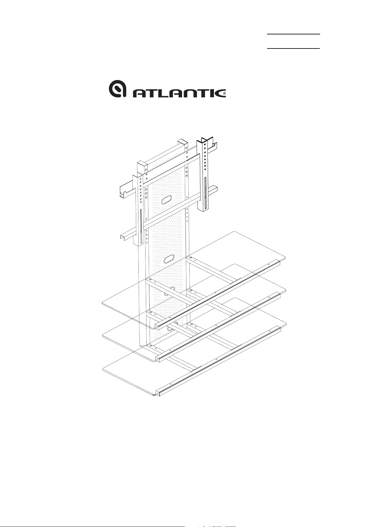
Infinity TV Stand with Mount
Fits PLASMA or LCD TV’s THAT MEASURE 37 to 42 inches. If parts are missing, DO NOT return to
the store.To order missing / replacement parts or assembly assistance please
call 1-800-747-2660 or mail customer_relations@atlantic-inc.com.
Page 2
Assembly Tips:
Become familiar with the instructions and all parts.
Make sure that all parts are in the box and in good condition.
Assemble the product on the open flat carton or a rug to protect the product and
your floor.
Some heavy products need a second person to assist in the assembly.
Use of power tools is not recommended.
It is strongly recommended that at least two people carry out the assembly.
Assemble the product close to a wall.
Screwing wall anchor into stud is very important to secure the stand.
.
With each step, first insert and hand-tighten all bolts and screws by hand. After
BOLTS
pattern (clockwise or counter clockwise).
Never let children climb on furniture or play with furniture.
Do not sit or stand on furniture.
Do not place a TV that is heavier than the recommended load rating on the
furniture surface.
Do not overload shelves.
are slightly screwed in, fully tighten bolts with Phillips screwdriver in sequential
!
Caution:
ALL
Use care when moving furniture. Furniture can tip over if moved improperly.
Only move furniture when it is empty of TV or other electronic components.
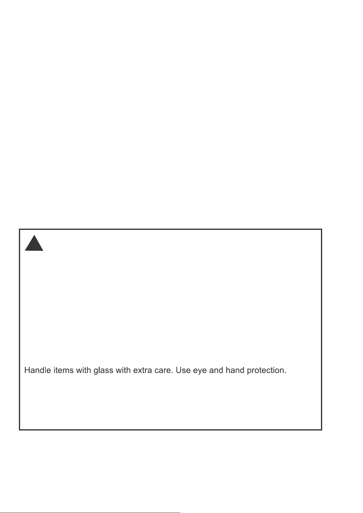
Improper handling can result in cuts and lacerations.
Do not install on sloping surface.
Care Instructions:
Use electrostatic dust cloths to clean furniture.
Do not set hot or cold containers directly on the furniture surface.
-1-
Page 3
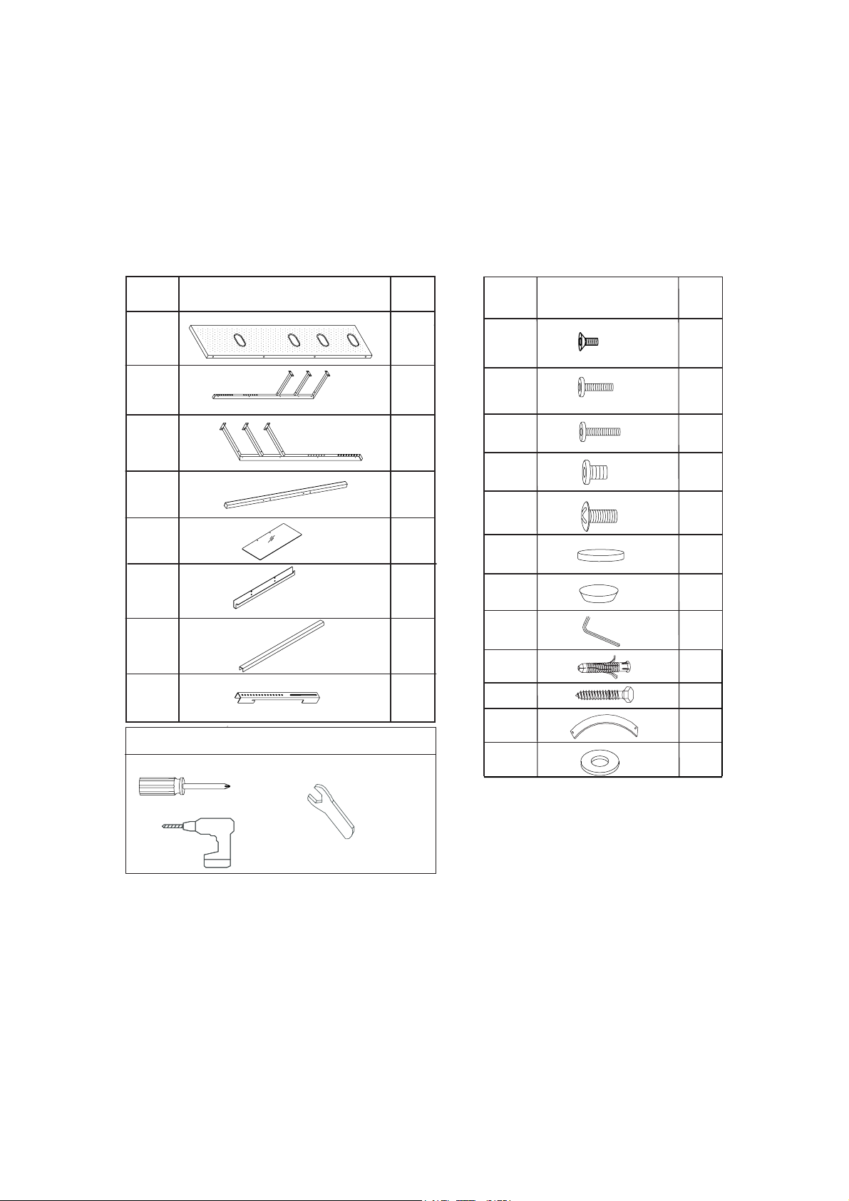
Part List
Item
A
B
C
D
E
G
H
Components parts list
Qty
1
1
1
3
3
1F
1
2
Item
I
J
K
L
M
N
O
P
Q
R
Components parts list
Qty
12
8
2
4
6
15
5
1
1
1
Tool needed (not included)
S
T
1
1
-2-
Page 4
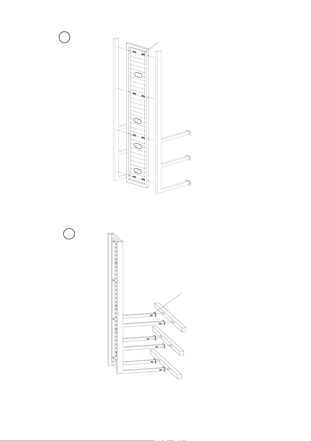
1
B
A
J*8
C
1-Attach frames (B) & (C) to the back panel (A) with screws (J).
2
I*12
B
C
D
D
D
2-Fasten beams (D) to the frames (B & C) with screws (I).
-3-
Page 5

3
B
C
N*15
D
D
D
O*5
3-Place pads (N) on the beams (D) and frames (B & C). Apply pads (O) at the
bottom of the unit.
4
A
F
L*4
E
E
E
4-Attach holder (F) to panel (A) with screws (L). Place glass (E) on the pads.
-4-
Page 6

5
M*6
E
E
E
5-Fast
en the glass (E) on the beams with screws (M). Do not over tighten screws.
6
H H
6-Fasten two TV mounting brackets(H) on the back panel of the TV. Detail
assembly instructions refer to next pages.
-5-
Page 7

PAY EXTRA CARE AND ATTENTION TO THIS STEP. MAKE SURE THE
APPROPRIATE
MOUNTING HARDWARE IS BEING USED PROPERLY.
1. Select correct Mounting Hardware according to the screw hole size on your TV, discard any remaining
Machine Screws or Spacers.
2. Carefully lay your Plasma/Flat Panel TV on its Face on a non-abrasive surface, making sure to lay
padding undermeath it so as not to damage the screen.
3. Place left Mounting Rail and Right Mounting Rail in the appropriate position, making sure they are
CENTERED on the back of the TV and LEVEL with one another.
MOUNTING HARDWARE LIST
HARDWARE
IDENTIFICATION
T1
T2
T3
U1
PICTURE
SIZE
(mm)
4 x 15
4 x 35
4 x 54
5 x 15
HEAD DIAMETER
(mm)
8
8
8
8
X
Ø4
U2
U3
V1
V2
V3
W1
W2
W3
5 x 35
5 x 54
6 x 15
6 x 35
6 x 54
8 x 15
8 x 35
8 x 54
10
10
10
14
14
14
8
8
Ø5
Ø6
Ø8
- 6 -
Page 8

7
For Flat Back TV
X
X
X
X
X
Ø4
(T1~T3 Screws)
X
Ø6
(V1~V3 Screws)
7-Insert Machine Screws through Dual-Hole Washers (X)
then into appropriate hole locate on left and right mounting brackets(H), and then into
TV.
(U1~U3 Screws)
(W1~W3 Screws)
(see Mounting Hardware list),
X
Ø5
X
Ø8
NOTE:The position of the Mounting Brackets and Hardware will be determined
by the type of TV that you have. These diagrams are not designed to
show the exact positioning; they are only to be used as a guide.
SECURE MACHINE SCREWS FULLY, BUT DO NOT OVER-TIGHTEN.
- 7 -
Page 9

8
7-A
F
H
side view
8-After mounting the brackets (H) to TV, hang TV onto holder (F), see (7-A).
9
H
G
A
K*2
T
s
9-Attach holder (G) to bracket (H), fix holder (G) and wall strap(S) to panel (A) with washer(T) and
screws (K).
-8-
Page 10

10
Tool needed(not included)
(Q) (R)
wall strap
R
(S)
wall
Q
10- Place wall strap (S) at desired position on the wall. Mark the hole position with a pencil. Drill a hole
on the pencil mark made on the wall with a 10mm size Drill Bit. Insert plastic anchor(Q) into the wall.
Fasten the wall strap(S) to the wall by inserting screw(R) through grommet in nylon strap(S) and then
into wall anchor.
Note:Screwing wall anchor into stud is very important in properly securing the stand.
- 9 -
Page 11

Max. 100 lbs
Max. 65 lbs
Max. 65 lbs
Max. 65 lbs
Product Warranty: Atlantic Inc., warrants to the original purchaser that its
products are free from defect in materials or workmanship. If after inspection,
we find that the product was defective in materials or workmanship, we shall
repair or replace the product at our discretion. This warranty does not cover
accidental damage, misuse, improper care or alteration and excludes claims
for incidental or consequential loss. This limited warranty applies to product
purchased in the U.S. and Canada.
This warranty gives you specific legal
rights and you may also have other rights which vary from State to State.
This warranty will last one year.
Keep this Instruction Manual for future reference.
Keep your original proof of purchase (store receipt).
If parts are missing, DO NOT return to the store.
To order missing / replacement parts or for assembly assistance please
contact customer_relations@atlantic-inc.com.
Or call 1-800-747-2660 M-F, 8am-5pm, P.S.T.
-10-
8
U.S. and other foreign patents pending /
Patentes de los EUA y países extranjeros en trámite /
Brevets en cours pour les États-Unis et autres pays /
U.S. und andere ausländische Patente sind hängig
All rights reserved / Derechos Reservados /
Tous droits réservés / Alle Rechte vorbehalten
Made in China / Hecho en China /
Fabriqué en Chine / Hergestellt in China
www.atlantic-inc.com
R1.1 080820 #36835516
 Loading...