

Atlantic WOYA 060 LFCA, WOYA 080 LFCA, WOYA 100 LFTA, 024127, 024128 Installation And Commissioning Instructions
Page 1
Installation
and commissioning
instructions
for professionals
to be kept by the user
for future reference
U0602594_1873_EN_3
06/09/2017
Alféa Extensa Duo A.I.
atlantic-comfort.com
FR NL DE EN IT
ES PT PL PT PT
Air/water heat pump
split 2 services
Outdoor unit Hydraulic unit
WOYA 060 LFCA 024127
WOYA 080 LFCA 024128
WOYA 100 LFTA
Page 2

" Installation
and maintenance regulations
The appliance must be installed and maintained by
an approved professional in accordance with current
regulations and codes of practice.
" Handling
The outdoor unit must not be placed in a horizontal
position during transport.
If not kept upright during transport, the appliance could
be damaged through displacement of the refrigerant
and damage to the compressor suspension.
Any damage caused by transportation in a horizontal
position is not covered by the warranty.
If necessary, the outdoor unit may be tilted only during
manual handling (to go through a door or up a staircase).
This operation must be conducted very carefully and the
appliance must be immediately restored to the upright
position.
" Containment of refrigeration circuits
All refrigeration circuits are sensitive to contamination
from dust and moisture. If any such pollutants penetrate
the refrigeration circuit, they can aect the reliability of
the heat pump.
" Make sure that the connections and refrigeration
circuits (hydraulic unit, outdoor unit) are
protected correctly.
" In the event of a subsequent failure and following
an inspection, the presence of moisture or
foreign bodies in the compressor oil would
automatically void the warranty.
- Check upon receipt that the ttings and refrigeration
circuit caps mounted on hydraulic unit and outdoor unit
are properly seated and secured (cannot be loosened
with bare hands). If this is not the case, tighten them
using a C spanner.
- Check also that the refrigeration connections are
sealed (plastic caps or tubes crimped at the ends
and brazed). If the caps must be removed during the
installation (tubes to be re-cut for example), put them
back as soon as possible.
" Hydraulic connections
The connection must comply with industry standard
practice according to current regulations.
Remember: Seal everything when tting in accordance
with industry standard practice for plumbing work:
- Use suitable seals (bre gasket, O-ring).
- Use Teon or hemp tape.
- Use sealing paste (synthetic depending on the case).
Use glycol/water mix if the minimum ow temperature
is set below 10°C. If you are using a glycol/water
mix, arrange for an annual check on the quality
of the glycol. Use monopropylene glycol only.
The recommended concentration is 30% minimum.
Never use monoethylene glycol.
Remember: The presence at installation of a
CB-type disconnection function, for preventing heating
water being returned to the drinking water system, is
required by articles 16.7 and 16.8 of the Local Plumbing
Regulations.
" In some installations, the presence of dierent
metals can cause corrosion problems; the
formation of metal particles and sludge can
appear in the hydraulic circuit.
" In this case, it is advisable to use a corrosion
inhibitor in the proportions indicated by the
manufacturer.
- Please refer to the chapter "Treatment of domestic
and heating water" in our price catalogue.
" You must also ensure that treated water does
not become corrosive.
Installation and Operating Manual "1873- EN"
Alféa Extensa Duo A.I. Heat Pump
- 2 -
Page 3
" Electrical connections
• Before any maintenance operation, ensure that
the general power supply is switched o.
• Specications of electricity supply
The electrical installation must be carried out in
accordance with current regulations.
Electrical connections will only be made once all other
installation operations (fastening, assembly, etc.) have
been completed.
" Warning!
The contract signed with the energy provider must
be sucient not only to cover the heat pump's power
requirements but also the combined sum of all the
appliances likely to be operating at the same time. If the
power is too low, check the power rating stated in your
contract with your energy provider.
Never use a power socket for the power supply.
The heat pump must be supplied directly with power
(without external switch) by special protected leads
from the electric panel via dedicated bipolar circuit
breakers, C curve for the outdoor unit, C curve for
the electrical heating and domestic water backups
(see tables page 37).
The electrical installation must be tted with a 30mA RCD.
This appliance is designed to operate using a nominal
voltage of 230 V +/- 10%, 50 Hz.
• General remarks on electrical connections
It is essential to maintain neutral-phase polarity when
making electrical connections.
Rigid wires are preferable for xed installations,
particularly in a building.
Tighten the cables using the cable glands to prevent the
feed wires from being accidentally disconnected.
The earth connection and its continuity must be ensured.
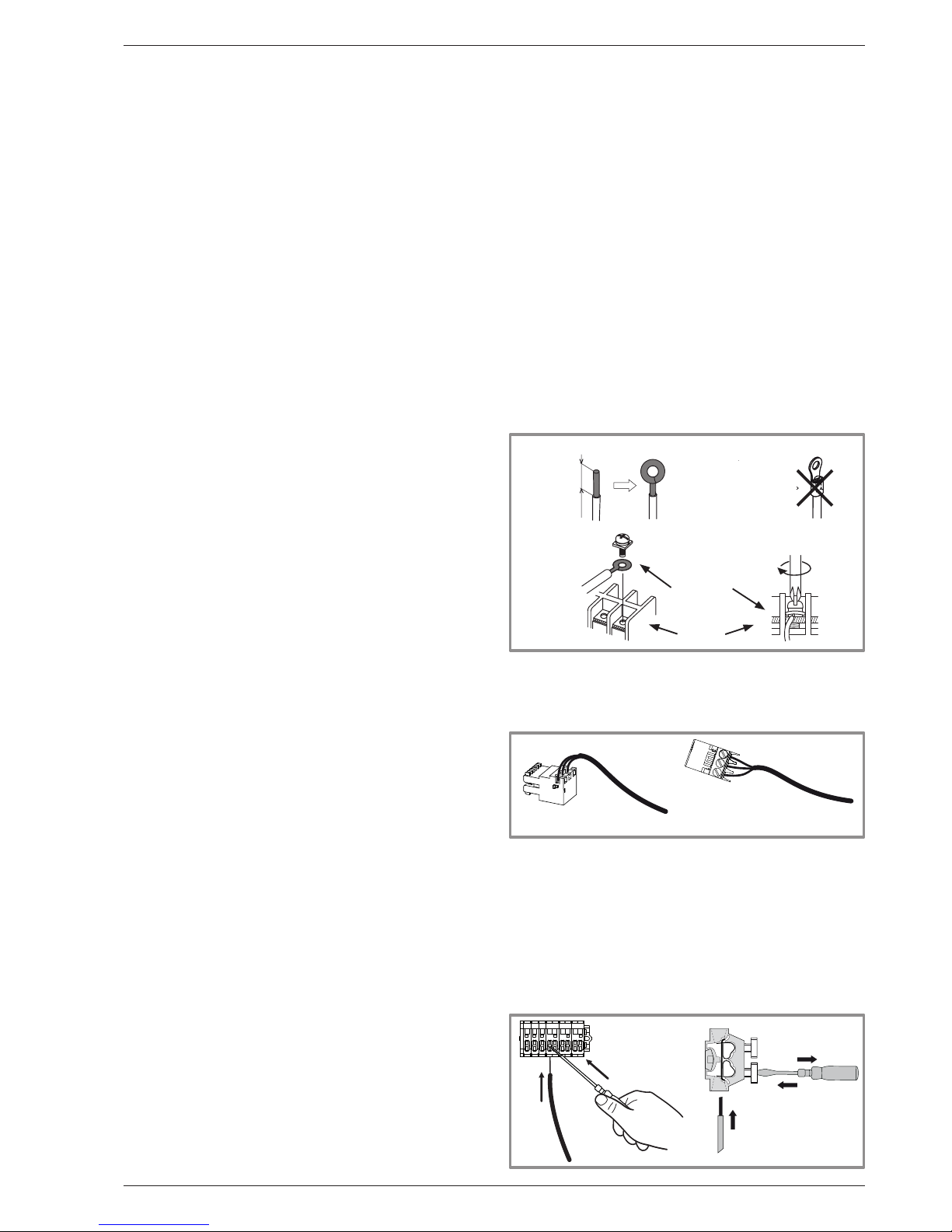
• Connecting to screw terminals
" The use of ring, spade or blade terminals or
caps is prohibited.
- Always select wire that complies with current
standards.
- Bare the end of the wire to around 25 mm.
- With round end pliers, form a loop with a diameter
which matches the tightening screws on the terminal.
- Tighten the terminal screw rmly onto the loop created.
Insucient tightening can cause overheating, leading
to breakdown or even re.
Rigid wire
Loop
25 mm
Spade
or blade
terminal
on exible
wire
is prohibited
Screw and special
washer
Terminal
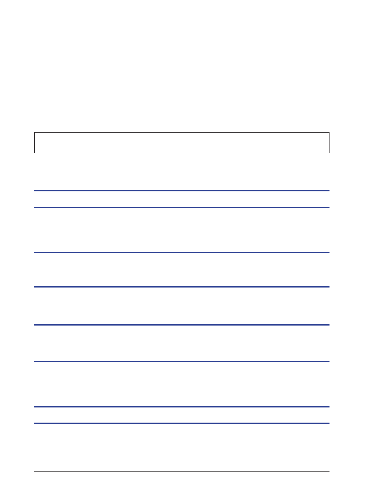
• Connecting to controller boards
- Remove the corresponding connector and make the
connection.
Pre-cabled bundle connector and/or screw connector
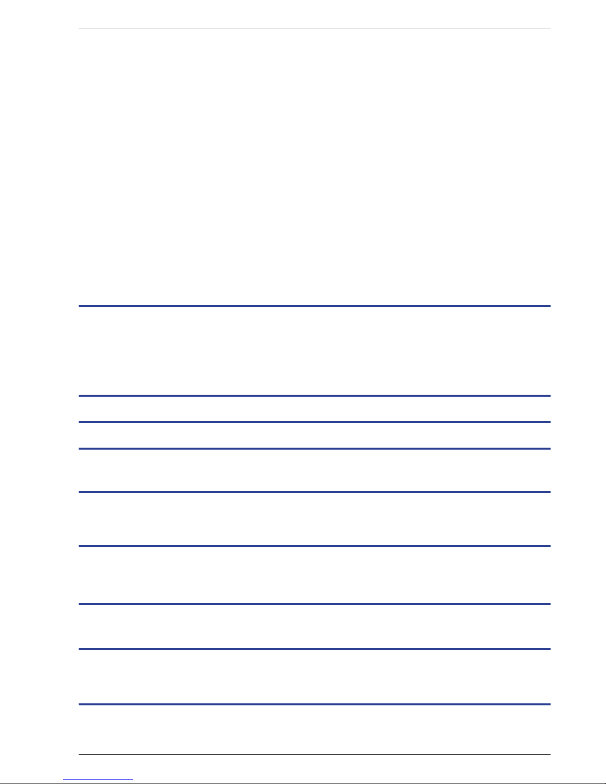
• Connecting to spring terminals
- Bare the end of the wire to around 10 mm.
- Push the spring with a screwdriver so that the wire
enters the cage.
- Slide the wire into the opening provided for this
purpose.
- Remove the screwdriver and then check that the wire
stays gripped by the cage by pulling on it.
2
1
3
Installation and Operating Manual "1873- EN" - 3 -
Alféa Extensa Duo A.I. Heat Pump
Page 4
Contents
Packing . . . . . . . . . . . . . . . . . . . . . . . .6
Unpacking and supplies . . . . . . . . . . . . . . . . 6
Denitions . . . . . . . . . . . . . . . . . . . . . . . 6
General characteristics . . . . . . . . . . . . . . . .7
Description. . . . . . . . . . . . . . . . . . . . . . 12
Operating principle . . . . . . . . . . . . . . . . . 14
Installation . . . . . . . . . . . . . . . . . . . . . . . . . . . . . . . . . . . 16
Installation of refrigeration connections . . . . . . . 16 Installation of the outdoor unit . . . . . . . . . . . . 18
Installation of the hydraulic unit . . . . . . . . . . . 20
Electrical connections . . . . . . . . . . . . . . . . . . . . . . . . . . . . . 36
Cable dimensions and protection rating . . . . . . . 37
Electrical connections on the outdoor unit side . . . 38
Electrical connections on the hydraulic unit side . . 39
Outside sensor . . . . . . . . . . . . . . . . . . . 40
Room sensor (option) . . . . . . . . . . . . . . . . 40
Description of the equipment . . . . . . . . . . . . . . . . . . . . . . . . . . 6
This appliance must be installed by qualied personnel holding a certicate of competence in the handling
of refrigerants.
Controller Interface . . . . . . . . . . . . . . . . . . . . . . . . . . . . . . 44
User Interface . . . . . . . . . . . . . . . . . . . . 44
Display Description . . . . . . . . . . . . . . . . . 45
Installer Menu . . . . . . . . . . . . . . . . . . . . 46
Navigating the Menus . . . . . . . . . . . . . . . . 46
Modifying Settings . . . . . . . . . . . . . . . . . . 47
Temperature control . . . . . . . . . . . . . . . . . 48
Refrigeration connections and lling the installation with gas . . . . . . . 21
Rules and precautions . . . . . . . . . . . . . . . . 21
Shaping the refrigeration pipes . . . . . . . . . . . 21
Checks and connection . . . . . . . . . . . . . . . 23
Filling the installation with gas . . . . . . . . . . . . 24
Hydraulic connection . . . . . . . . . . . . . . . . . . . . . . . . . . . . . 30
Connecting the hydraulic unit to the heating circuit . 30
Connecting to the DHW circuit . . . . . . . . . . . 32
Filling and bleeding the installation . . . . . . . . . 33
Heating circulation pump speed settings . . . . . . 34
Commissioning . . . . . . . . . . . . . . . . . . . . . . . . . . . . . . . . . 42
Installation and Operating Manual "1873- EN"
Alféa Extensa Duo A.I. Heat Pump
- 4 -
Page 5
Basic Hydraulic Layout . . . . . . . . . . . . . . . . . . . . . . . . . . . . 68
Electrical Cabling Plans . . . . . . . . . . . . . . . . . . . . . . . . . . . . 70
Fault Diagnosis . . . . . . . . . . . . . . . . . . . . . . . . . . . . . . . . . 74
Checking the hydraulic circuit . . . . . . . . . . . . 76
Maintenance of the DHW tank. . . . . . . . . . . . 76
Checking the outdoor unit . . . . . . . . . . . . . . 76
Checking the electrical circuit . . . . . . . . . . . . 76
Other maintenance . . . . . . . . . . . . . . . . . . . . . . . . . . . . . . . 77
Emptying the hydraulic unit . . . . . . . . . . . . . 77
Distribution valve . . . . . . . . . . . . . . . . . . 77
ACI check . . . . . . . . . . . . . . . . . . . . . . 77
Start-up procedure . . . . . . . . . . . . . . . . . . . . . . . . . . . . . . . 78
Start-up check-list . . . . . . . . . . . . . . . . . . 78 Commissioning technical datasheet . . . . . . . . . 80
ErP performance gures . . . . . . . . . . . . . . . . . . . . . . . . . . . . 82
Denition of ErP . . . . . . . . . . . . . . . . . . . 82
ERP specication . . . . . . . . . . . . . . . . . . 82
Package datasheet . . . . . . . . . . . . . . . . . 84
Instructions for the end user . . . . . . . . . . . . . . . . . . . . . . . . . 85
Controller Menu . . . . . . . . . . . . . . . . . . . . . . . . . . . . . . . . 50
Menu Structure . . . . . . . . . . . . . . . . . . . 50
Installed options . . . . . . . . . . . . . . . . . . . 51
Hydraulic conguration . . . . . . . . . . . . . . . 51
Heat Pump Conguration . . . . . . . . . . . . . . 56
System status . . . . . . . . . . . . . . . . . . . . 58
Auxiliary functions . . . . . . . . . . . . . . . . . . 60
Settings . . . . . . . . . . . . . . . . . . . . . . . 62
Easy Start . . . . . . . . . . . . . . . . . . . . . . 66
Faults in the Hydraulic Unit . . . . . . . . . . . . . 74 Faults in the outdoor unit . . . . . . . . . . . . . . 75
Maintenance of the installation . . . . . . . . . . . . . . . . . . . . . . . . 76
Installation and Operating Manual "1873- EN" - 5 -
Alféa Extensa Duo A.I. Heat Pump
Page 6

1.1 Packing
• 1 package: Outdoor unit.
• 1 package: Hydraulic unit and outside temperature
sensor.
1.2 Unpacking and supplies
While the courier is still present, carefully check the
general appearance of the appliances and check
that the outdoor unit has not been laid in a horizontal
position.
In the event of a dispute, send any relevant reservations
to the carrier in writing within 48 hours and send a copy
of the letter to Customer Services.
1.3 Denitions
- Split: The heat pump consists of two elements
(an outdoor unit to be installed outdoors and a hydraulic
unit to be installed inside the dwelling).
- Air/water: The surrounding air is the energy source.
This energy is transmitted to the heating circuit water
by the heat pump.
- Inverter: The fan and compressor speeds are
modulated according to the heating requirements.
This technology enables you to save on energy and
operate on a single-phase power supply, whatever
the heat pump's output, by avoiding pulling signicant
amounts of current at start-up.
- COP (Coecient of Performance): This is the
relationship between the energy transmitted to the
heating circuit and consumed electrical energy.
1 Description of the equipment
Installation and Operating Manual "1873- EN"
Alféa Extensa Duo A.I. Heat Pump
- 6 -
Packing contents list
Heat Pump Outdoor unit Hydraulic unit
Model Export code Reference Code Reference Code
Alféa Extensa Duo A.I. 5 526236
WOYA060LFCA 700171
Alféa Extensa Duo A.I. 5 024127
Alféa Extensa Duo A.I. 6 526237
Alféa Extensa Duo A.I. 6-8-10 024128
Alféa Extensa Duo A.I. 8 526238 WOYA080LFCA 700172
Alféa Extensa Duo A.I. 10 526239 WOYA100LFTA 700173
Optional equipment
• Dual circuit kit (code 074011)
for connecting 2 heating circuits.
• Electrical back-ups kit (code 074044)
• Boiler connection kit (code 073990)
for connecting a boiler to the heat pump.
• Wireless room sensor A59(code 074208) for
correcting the ambient temperature.
• Wireless room sensor A75 (code 074213),
Wireless room sensor A78 (code 074214)
for correcting the ambient temperature and
programming the heat pump.
• Cooling kit (code 075328).
• High ow rate circulation pump kit (code 074077)
for the installation of 1 underoor heating circuit.
• Anti-vibration blocks (code 523574).
• White PVC oor support (ref. 809532) or
Black rubber oor support (ref. 809536).
Operating Range
This heat pump provides:
- Heating in winter,
- The management of electrical backups*, for extra
heating on the coldest days,
or
- Installation with boiler connection* for extra heating on
the coldest days,
- Management of two heating circuits*,
- Production of domestic hot water.
- Cooling in summer* (for underoor heating-cooling
system or fan-convectors).
*: These options require the use of additional kits
(see chapter "Required accessory" or "Optional equipment").
Page 7
1.4 General characteristics
Model name Alféa Extensa Duo A.I. 5 6 8 10
Rated heating performances (outdoor temp. / ow temp.)
Heat output
+7°C/+35°C - Underoor heating system kW 4.50 6.00 7.50 10.00
-7°C/+35°C - Underoor heating system kW 4.10 4.60 5.70 7.40
+7°C/+45°C - LT radiator kW 4.50 5.10 6.20 8.27
-7°C/+45°C - LT radiator kW 4.10 4.45 5.05 7.40
+7°C/+55 °C - Radiator kW 4.50 4.50 5.00 7.00
-7°C/+55°C - Radiator kW 3.70 3.85 5.20 7.00
Power consumption
+7°C/+35°C - Underoor heating system kW 1.00 1.41 1.84 2.49
-7°C/+35°C - Underoor heating system kW 1.47 1.74 2.23 2.97
+7°C/+45°C - LT radiator kW 1.31 1.50 1.87 2.53
-7°C/+45°C - LT radiator kW 1.86 2.04 2.47 3.70
+7°C/+55°C - Radiator kW 1.79 1.79 1.94 2.86
-7°C/+55°C - Radiator kW 2.20 2.33 3.34 4.15
Coecient of Performance (COP) (+7°C/+35°C) 4.52 4.26 4.08 4.02
Electrical specications
Electrical voltage (50 Hz) V 230
Maximum current for appliance A 11 12.5 17.5 18.5
Nominal current A 4.5 6.3 8.1 10.9
Maximum current of the Heating system electrical backup (option) A 13.05 / 26.1
Power of the Heating system electrical backup (option) kW 6 kW
Fan actual power consumption W 49 49 49 100
Circulation pump actual power consumption W 24
Maximum power consumed by the outdoor unit W 2530 2875 4025 4255
DHW electrical backup power W 1500
Rate according to EN14825 0.0100 0.0070 0.0057 0.0044
Hydraulic Circuit
Maximum operating pressure heating / hot water tank MPa (bar) 0.3 (3) / 1 (10)
Flow rate of the hydraulic circuit for 4°C<Δt<8°C
(rated conditions) minimum / maximum
l/h 490 / 980 650 / 1300 810 / 1620 1080 / 2160
Miscellaneous
Weight of outdoor unit Kg 41 41 42 60
Weight of hydraulic unit (empty / full of water) Kg 155 / 373
Water capacity of the hydraulic unit / hot water tank l 24 / 190
Noise level at 1 m 1 (hydraulic unit) dB (A) 39
Sound power level in accordance with EN 12102 2 (hydraulic unit) dB (A) 46
Noise level at 5 m 1 (outdoor unit) dB (A) 40 40 47 47
Sound power level in accordance with EN 12102 2 (outdoor unit) dB (A) 63 63 69 69
Heating system operating limits
Outdoor temperature min/max °C -20 / +35
Max. heating water ow temperature underoor heating °C 45
Max. heating water ow temperature low temperature radiator °C 52
Refrigeration circuit
Gas pipe diameters Inches 1/2 1/2 5/8 5/8
Liquid Piping Diameters Inches 1/4 1/4 1/4 3/8
Factory ll of refrigerant R410A 3 g 1100 1100 1400 1800
Maximum operating pressure MPa (bar) 4.15 (41.5)
Minimum / Maximum length of pipes
4
m 5 / 15
Maximum length of pipes 5 / Maximum level dierence m 30 / 20
1
Sound pressure level at (x) m from the appliance, 1.5m o the ground, open
eld directionality 2.
2
The sound power level is a laboratory measurement of the emitted sound
power. It does not correspond to a measurement of the perceived sound power.
3
Refrigerant R410A as per NF EN 378.1 standard.
4
Filling with refrigerant R410A is done at the factory.
5
Taking into account a possible additional ll of refrigerant R410A
(see "Additional lling", page 27).
- 7 -
Alféa Extensa Duo A.I. Heat Pump
Installation and Operating Manual "1873- EN"
Page 8
650
AIR
AIR
370
830
21
196
99
9
900
77
12
33031
147
170
400
540
4 holes Ø11
62
790
290
18 23
209
352
620
320
16
110
175
AIR
AIR
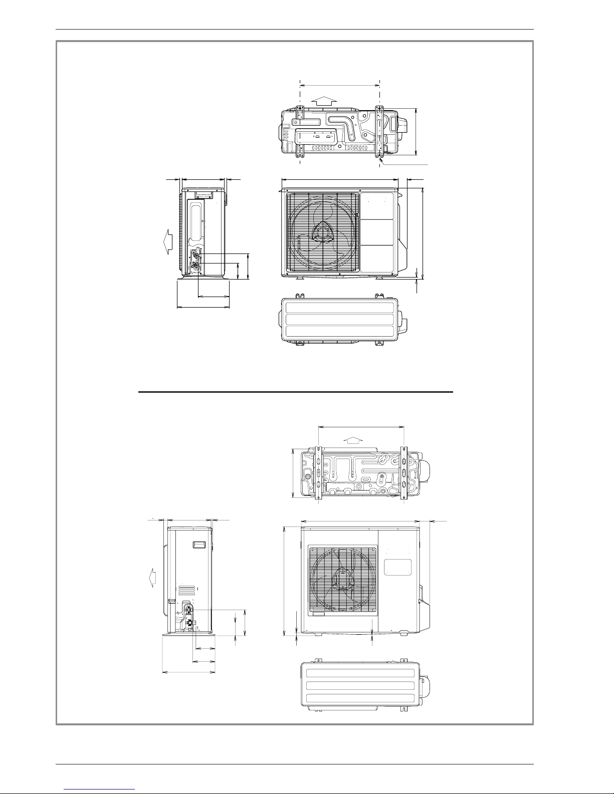
gure 1 - Dimensions in mm
4 holes
Installation and Operating Manual "1873- EN"
Alféa Extensa Duo A.I. Heat Pump
- 8 -
" Outdoor Unit,
Alféa Extensa Duo A.I. 5, 6 and 8
" Outdoor Unit,
Alféa Extensa Duo A.I. 10
Page 9
175 210
47
1296
648
1141
1190
297
55
244
1841
1851
678
684
71
55
507
144
608
115
1679
1611
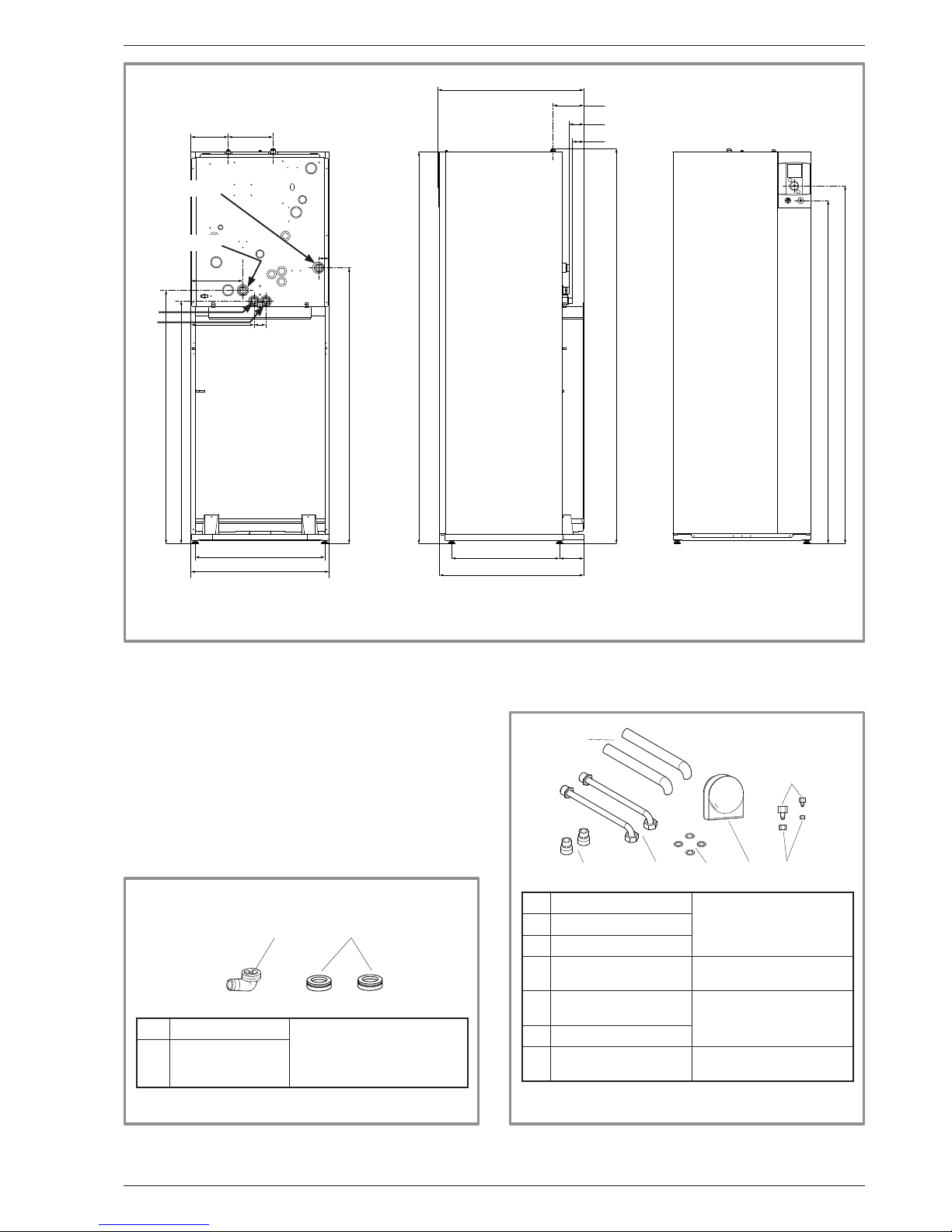
gure 2 - Dimensions in mm
Space requirements of the hydraulic unit, see gure 15, page 20.
Back view
Heating ow.
DHW
DCW
Heating return.
Side view Front view
" Hydraulic unit
gure 3 - Accessories provided with the outdoor unit gure 4 - Accessories provided with the hydraulic unit
1*
2*
3**
1* Elbow
for condensate evacuation.
2*
Plugs (x2)
(depending on
model)
* only for Alféa Extensa Duo A.I. 10.
1 Dielectric connections
for connections to the
DHW circuit
2 DCW pipes
3 Gaskets
4 Outside sensor
to monitor the outside
temperature
5
Adapter 1/2" - 5/8"
and/or 1/4" - 3/8"
for ared connections
to the hydraulic unit
(depending on model).
6 Nut 1/2" and/or 1/4"
10 Insulation tube
to insulate connections
and tubes
64
10
5
3
2
1
Installation and Operating Manual "1873- EN" - 9 -
Alféa Extensa Duo A.I. Heat Pump
Page 10
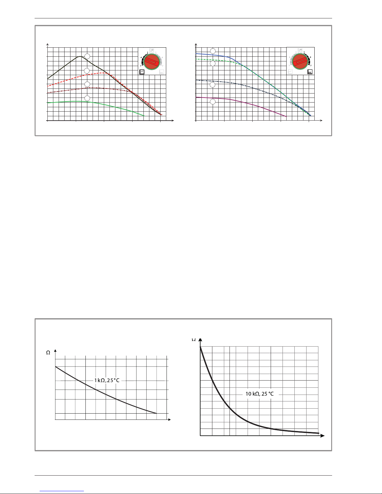
gure 5 - Available hydraulic pressures and ow rates
gure 6 - Ohmic sensor values (Hydraulic unit)
-50
1000
10000
43907
2490
338
-25025 50 75
°C
°C
0
2500
5000
7500
10000
12500
15000
17500
20000
22500
25000
27500
30000
32500
0102030405060708090 100
Outside sensor QAC34
HP return sensor.
HP ow sensor.
0
1
2
3
4
5
6
7
8
mCE
1 mbar=10 mmCE=100 Pa
m/h
3
1
1,5 20,50
1
3
55
77
0
1
2
3
4
5
6
7
8
mCE
1 mbar=10 mmCE=100 Pa
m/h
3
1
1,5 20,50
1
3
55
77
Variable pressure Constant pressure
Installation and Operating Manual "1873- EN"
Alféa Extensa Duo A.I. Heat Pump
- 10 -
Page 11
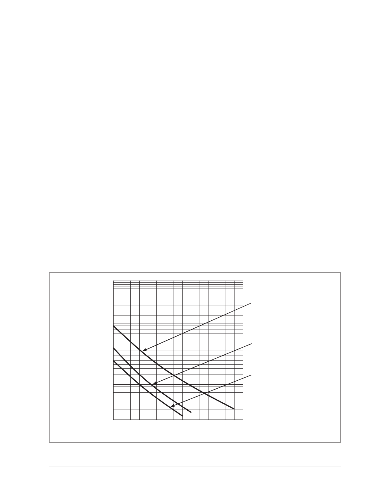
gure 7 - Ohmic sensor values (Outdoor unit)
-20 -10 0 10 20 30 40 50 60 70 80 90 100 110 120 130
10000
1000
100
10
1
- Compressor.
- Discharge.
- Condensation.
- Expansion valve.
- Evaporator inlet.
- Outdoor
Temperature °C
Ohmic value (kΩ)
Installation and Operating Manual "1873- EN" - 11 -
Alféa Extensa Duo A.I. Heat Pump
Page 12
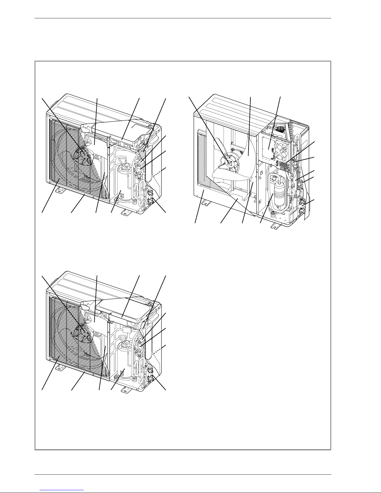
1.5 Description
gure 8 - Outdoor unit components
1
2
3
4
6
5
8
10
9
1211
7
1
2
3
4
6
5
10
9
1211
7
8
1
2
3
4
6
5
8
10
9
1211
7
Key:
1 - High performance and low noise impeller.
2 - Electrical motor with variable "inverter" operation.
3 - "Inverter" control unit.
4 - Connection terminal blocks
(power supply and interconnection).
5 - Refrigerant storage bottle.
6 - 4-way valve.
7 - Anti-corrosion treated bodywork.
8 - Main circuit electronic expansion valve.
9 - Noise and thermally insulated "inverter" compressor.
10 - Refrigeration connection valves (ared connectors) with
protective caps.
11 - Holding tank with condensate drain hole.
12 - High-performance exchange surface evaporator;
anti-corrosion treated hydrophilic aluminium ns and
grooved copper tubes.
Installation and Operating Manual "1873- EN"
Alféa Extensa Duo A.I. Heat Pump
- 12 -
" Alféa Extensa Duo A.I. 5 and
6
" Alféa Extensa Duo A.I. 8
" Alféa Extensa Duo A.I. 10
Page 13
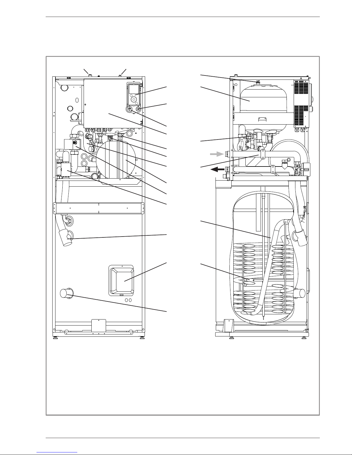
Key:
1 - Electric control box.
2 - Controller / User interface.
3 - Start/stop switch.
4 - Hydraulic unit circulation pump.
5 - Distribution valve.
6 - "Gas" refrigeration connection.
7 - "Liquid" refrigeration connection.
8 - Condensation sensor.
9 - Drain valve.
10 - Safety valve.
11 - Safety thermostat.
12 - Pressure gauge.
13 - Manual bleeder valve.
14 - Expansion vessel.
15 - Condenser.
17 - DHW electrical backup.
Sensors:
21 - HP return sensor.
22 - DHW sensor.
23 - HP ow sensor.
gure 9 - Hydraulic unit components
3
12
1
10
4
9
8
21
23
14
5
17
22
11
9
9
2
15
13
6 7
Installation and Operating Manual "1873- EN" - 13 -
Alféa Extensa Duo A.I. Heat Pump
Page 14
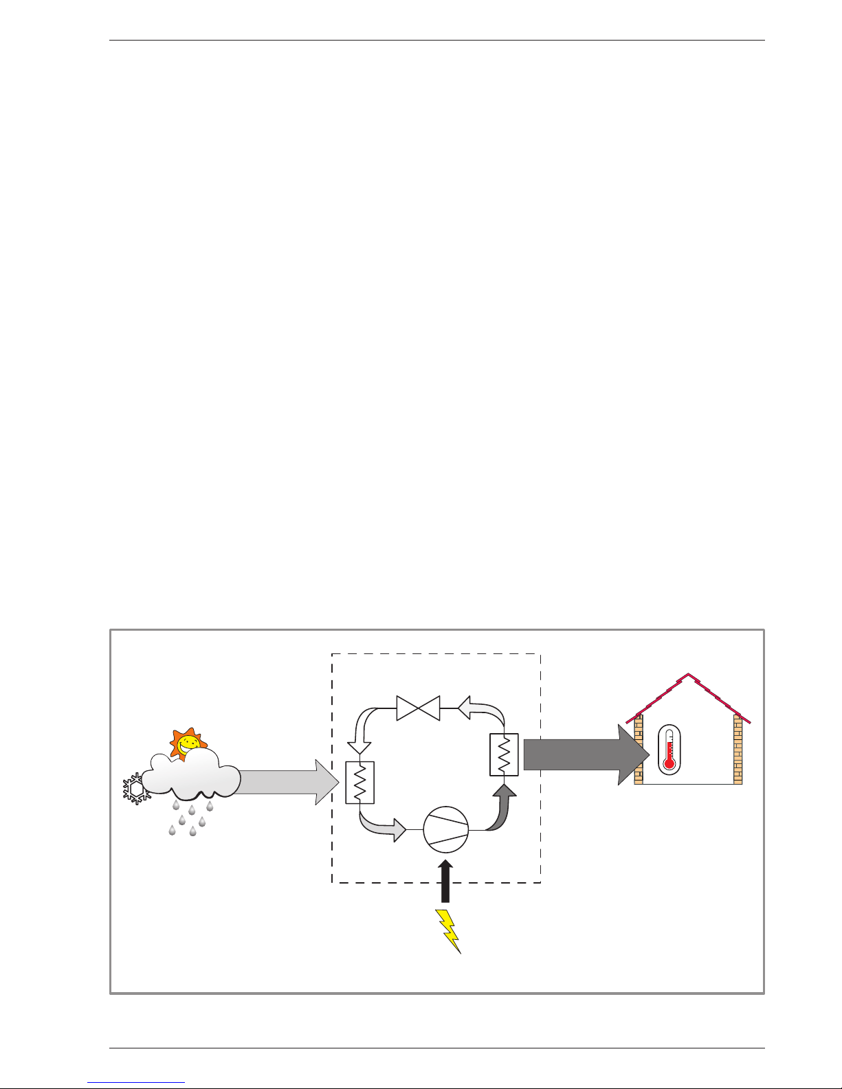
1.6 Operating principle
The heat pump transmits the energy contained in the
surrounding air into the dwelling to be heated and for
production of domestic hot water.
The heat pump consists of four main parts, in which a
refrigerant (R410A) circulates.
- In the evaporator (ref. 12, gure 8, page 12):
The calories are taken from the outside air and
transmitted to the refrigerant. Because it has a low
boiling point, it changes from a liquid to a vapour, even
in cold weather (down to -20°C outside temperature).
- In the compressor (ref. 9, gure 8, page 12):
The vaporised refrigerant is pressurised and takes on
even more calories.
- In the condenser (ref. 15, gure 9):
The energy of the refrigerant is transmitted to the
heating circuit. The refrigerant returns to its liquid state.
- In the expansion valve (ref. 8, gure 8, page 12):
The liqueed refrigerant is returned to a low pressure
and regains its initial temperature and pressure.
The heat pump is equipped with a controller which
controls the room temperature based on the outdoor
temperature measurement. The room thermostat
(option) provides a corrective action for the temperature
control.
The hydraulic unit is tted with an electrical backup or
boiler connection* which intervenes to provide additional
heat during the coldest periods.
• Control functions
- The heating circuit's ow temperature is controlled by
the temperature control.
- Depending on the heating ow temperature, the
outdoor unit's power is modulated by the "Inverter"
compressor.
- Control of the backup electrical heating*.
- The daily timer program is used to set the periods
where the ambient temperature is comfortable or
reduced.
- Summer/winter time mode switchover is automatic.
- Management of the boiler backup*.
- Room sensor*: The room sensor provides a corrective
action for the temperature control.
- Control of a second heating circuit*.
- Domestic hot water: Heating timer program,
management of the DHW circulation pump.
- Managing cooling*.
* Where the heat pump is tted with options and associated kits.
• Protective functions
- Anti-legionella cycle for domestic hot water.
- Anti-corrosion tank protection with titanium anode
(ACI).
- Frost protection: Frost protection cuts in if the heating
circuit's ow temperature falls below 5°C (provided
that the heat pump's electrical power supply is not
interrupted).
8
7
6
5
4
3
2
1
0
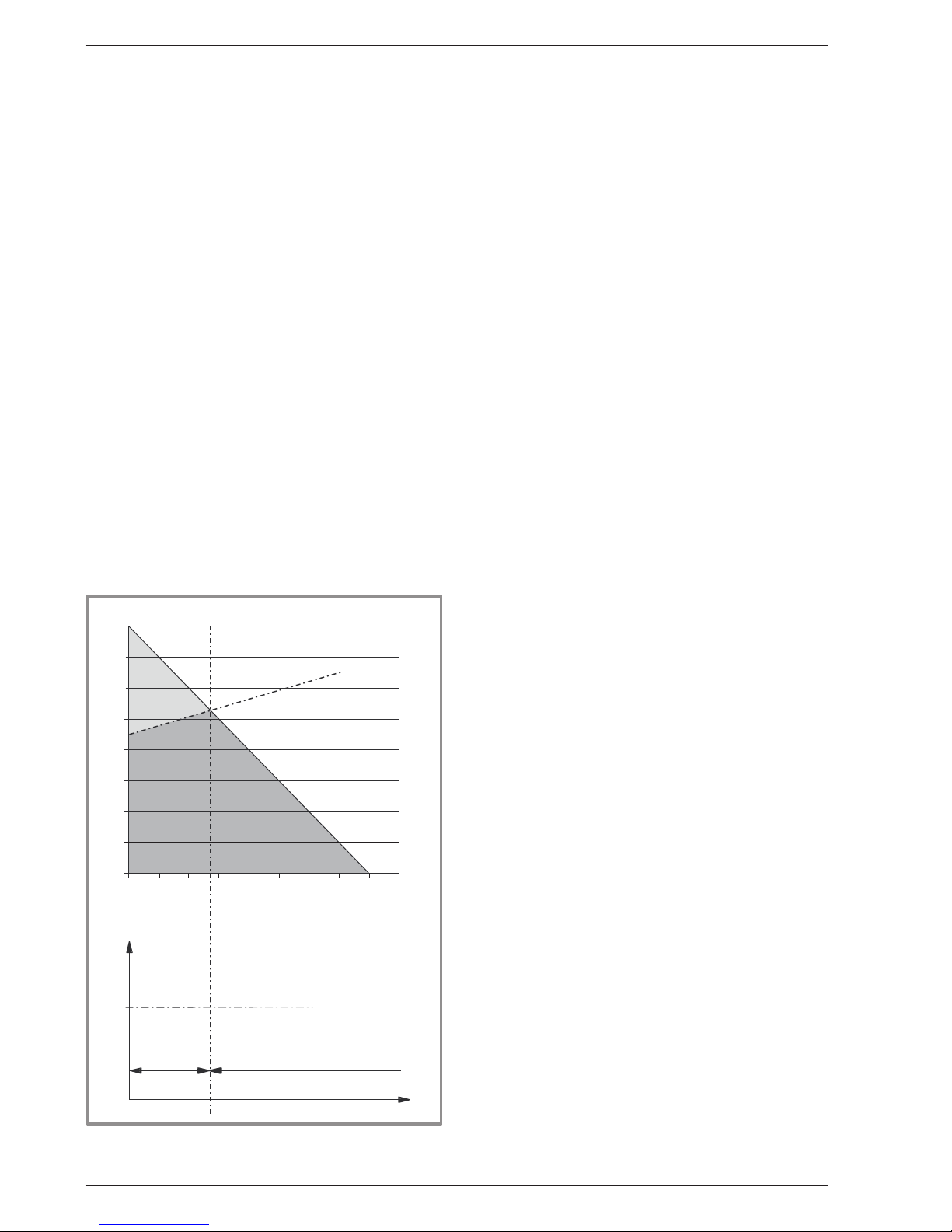
-20 -15 -10 -5 0 510152025
46
Dwelling heat loss (kW)
Outdoor temperature (°C)
Outdoor temperature (°C)
HP power
gure 10 - Examples and operating limits
Max
authorised HP
start-up temp.
Water return temperature (°C)
HP only
Heat Pump
HP +
electrical
backup
Backup
Installation and Operating Manual "1873- EN"
Alféa Extensa Duo A.I. Heat Pump
- 14 -
Page 15
• Domestic hot water (DHW) operating principle
Two domestic hot water (DHW) temperatures can be
set: comfort and reduced.
The default DHW program is set to the comfort
temperature between 00:00 and 05:00 and between
14:30 and 17:00 and to the reduced temperature for the
rest of the day. This optimises electrical consumption
while ensuring comfortable water temperatures.
The reduced temperature setpoint may be useful to
avoid restarting the DHW too often and for too long
during the day.
The production of domestic hot water (DHW) is started
when the temperature in the tank drops to 7°C below
the temperature setpoint.
The heat pump produces the domestic hot water, which
is then additionally heated, if required, by the tank's
electrical backup or by the boiler. To ensure a DHW
setpoint over 55°C, the electrical backup heating must
be left on.
gure 11 - Heat pump operating principle
Ev
Dt
Cn
Cp
1kW
COP 4
4kW
20 °C
PAC
PAC - Heating Pump
Ev - Evaporator
Cp - Compressor
Cn - Capacitor
Dt - Expansion Valve
Air energy
Heat produced
Electrical
energy
consumed
If the contract signed with the energy provider includes
a day/night tari, the electrical backup is subject to the
supplier’s power tari and the comfort temperature may
only be reached at night.
If no particular contract has been signed, the comfort
temperature can be reached at any time, including
during the day.
The production of DHW takes priority over heating;
nevertheless the production of DHW is managed
by cycles that regulate the amount of time assigned
to heating and production of DHW in the event of
simultaneous demand.
Anti-legionella cycles can be programmed.
• Fan convectors with integrated control system
Do not use a room sensor in the area in question.
Installation and Operating Manual "1873- EN" - 15 -
Alféa Extensa Duo A.I. Heat Pump
Page 16
2 Installation
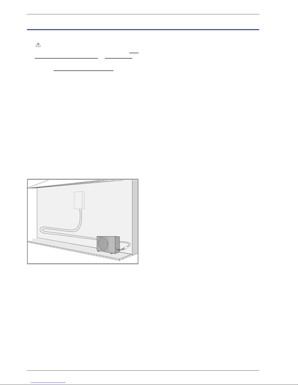
2.1 Installation of refrigeration connections
" Bend the pipes into position and make holes
for them through the oor or walls either with
their protective caps in place or after brazing.
" Keep the protective caps in place or ends brazed
until the appliance is commissioned.
The outdoor unit must be connected to the hydraulic unit
only with brand new separately insulated copper
connections (refrigerant quality).
Maintain the same pipe diameters (gure 19).
Observe the maximum and minimum distances between
the hydraulic unit and the outdoor unit (gure 19, page
22); the guarantee of performance and the service
lifespan of the system depend on this.
The minimum length of the refrigeration connections
for correct operation is 5 m.
The appliance's warranty will be void if it is operated
with refrigeration connections less than 5 m long
(tolerance +/- 10%).
If the refrigeration connections are exposed to
weathering or UV radiation and the insulation is not
resistant, protection must be provided.
gure 12 - Example of recommendation
for layout of refrigeration connections
Installation and Operating Manual "1873- EN"
Alféa Extensa Duo A.I. Heat Pump
- 16 -
Page 17
Installation and Operating Manual "1873- EN" - 17 -
Alféa Extensa Duo A.I. Heat Pump
Page 18
2.2 Installation of the outdoor unit
2.2.1 Installation precautions
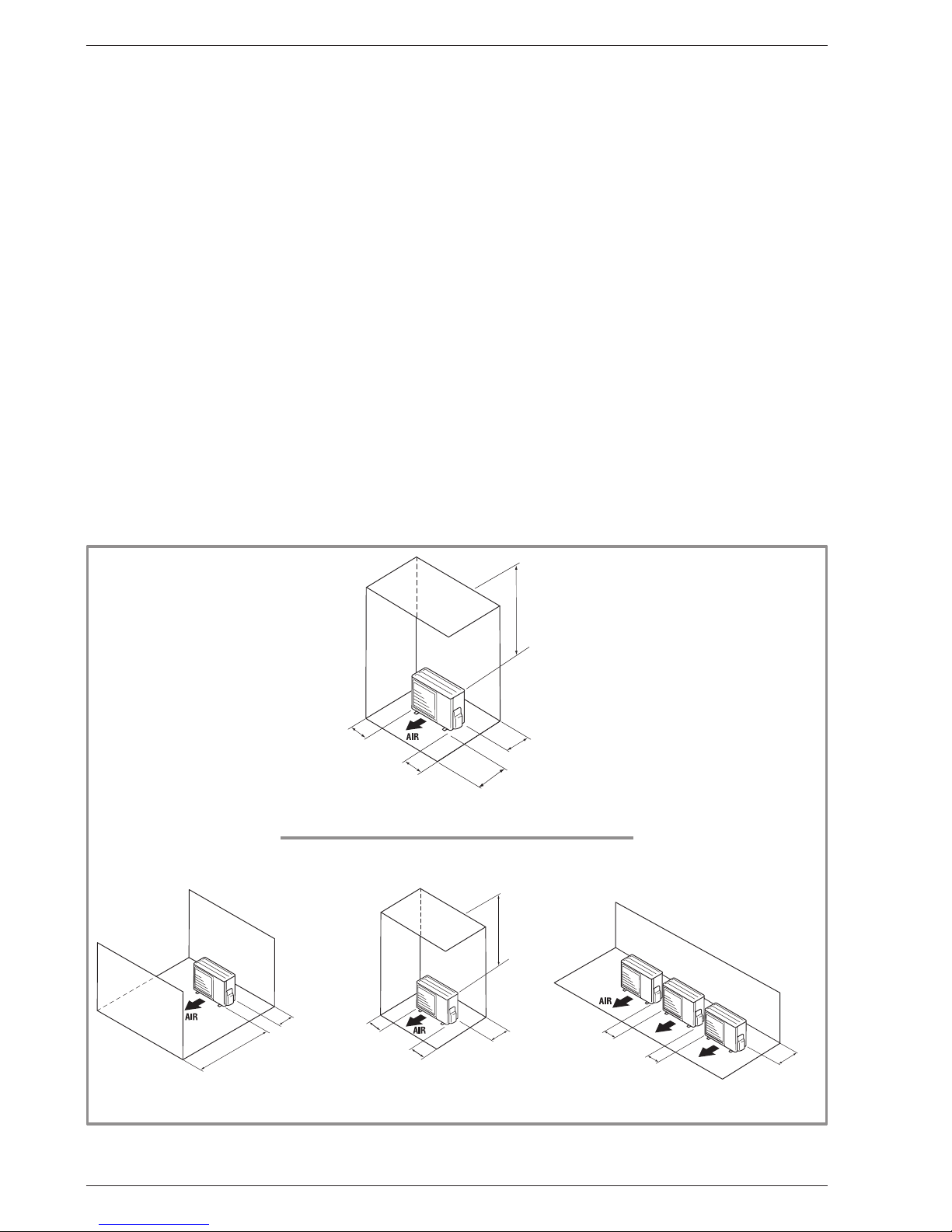
" The outdoor unit must only be installed
outside. If a shelter is required, it must have
broad openings on all 4 sides and installation
clearances must be observed (gure 13).
• Choose the location of the appliance after discussion
with the client.
• We recommend choosing a site that is sunny but
sheltered from strong cold prevailing winds.
• The unit must be easily accessible for future installation
and maintenance work (gure 13).
• Ensure that connections to the hydraulic unit can be
made easily.
• The outdoor unit is able to withstand bad weather but
avoid installing it in a position where it is likely to be
exposed to signicant dirt or owing water (e.g. under
a broken gutter).
• Water may ow out of the outdoor unit when it is
operating. Do not install the unit on a paved terrace;
choose a well-drained location (e.g. gravel or sand).
If installation is carried out in an area where the
temperature stays below 0°C for long periods, check
that the presence of ice does not present any danger.
A drainage pipe can also be connected to the outdoor
unit (gure 14).
• Nothing should obstruct the air circulation through the
evaporator and out from the fan (gure 13).
• Keep the outdoor unit away from heat sources and
ammable products.
gure 13 - Minimum installation clearances around the outdoor unit
600 mm
or more
100 mm
or more
250 mm or more
(Service space)
100 mm
or more
300 mm
or more
600 mm or more
250 mm
or more
250 mm
or more
300 mm
or more
600 mm or more
100 mm
or more
100 mm
or more
300 mm or more
(Service space)
300 mm
or more
" Alféa Extensa Duo A.I. 5, 6 and 8
" Alféa Extensa Duo A.I. 10
Minimum
Minimum
Minimum
Minimum
Minimum
Minimum
Minimum
Minimum
Minimum
Minimum
Minimum
Minimum
Minimum
Minimum
Installation and Operating Manual "1873- EN"
Alféa Extensa Duo A.I. Heat Pump
- 18 -
Page 19
• Make sure that the unit does not disturb the
surrounding area or inhabitants (noise level, draught,
low temperature of the ejected air freezing the plants
in its path).
• The surface on which the appliance is installed must:
- Be permeable (soil, gravel, etc.).
- Support its weight easily.
- Allow a solid fastening base,
- Not transmit any vibration to the dwelling. Anti-vibratory
blocks are available as an option.
• The wall bracket cannot be used where it is likely to
transmit vibrations. Installing the unit on the ground is
preferred.
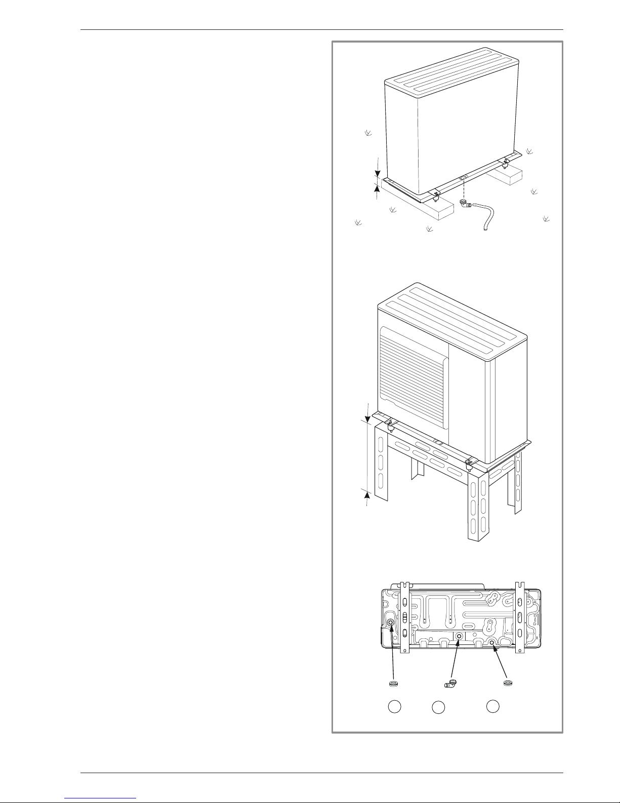
2.2.2 Positioning Outdoor Unit
The outdoor unit must be raised at least 50 mm
above ground level. In areas prone to snow, this
height should be increased but should not exceed
1.5 m (gure 14).
- Fasten the outdoor unit by means of screws and
rubber tightening or toothed lock washers to prevent
them from coming loose.
" Warning
In areas with heavy snowfall, if the intake and outlet
of the outdoor unit is blocked with snow, heating may
become dicult and a failure is likely to occur.
Construct a canopy or place the unit on a high stand
(local conguration).
- Place the unit on a solid stand in order to minimise
impacts and vibrations.
- Do not place the unit directly on the ground as this will
cause problems.
2.2.3 Condensate drain pipe
(see gure 14)
" The outdoor unit can generate a large volume of
water (called condensate).
If the use of a drain pipe is necessary:
- Install the condensate drain pan (optional / code 074008)
for Alféa Extensa Duo A.I. models 5, 6 and 8 only.
- Use the elbow provided (C) and connect a 16 mm-diameter
hose for draining the condensate.
- Use the plug(s) provided (B) to block the opening of
the condensate drain pan.
Allow for the condensate to ow away under the force of
gravity (waste water, rain water, gravel bed).
" If installation is carried out in an area where the
temperature stays below 0°C for long periods,
equip the drain pipe with trace heating to avoid
it icing up. Trace heating must heat not only the
drain pipe but also the bottom of the appliance's
condensate collection tank.
gure 14 - Installation of the outdoor unit
evacuation of condensates
Installation and Operating Manual "1873- EN" - 19 -
Alféa Extensa Duo A.I. Heat Pump
H
H
C
* In areas with heavy snowfall,
(H) must be higher than the average snow layer
B
B
C
" Only Alféa Extensa Duo A.I. 10
Page 20
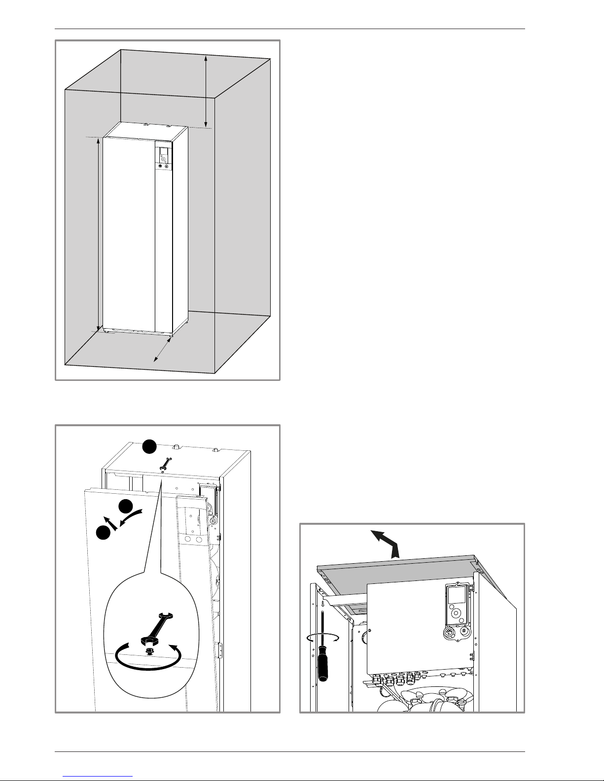
gure 15 - Minimum installation clearances
around the hydraulic unit and
distances away from fuel storage areas
1000
1841
300
2.3 Installation of the hydraulic unit
2.3.1 Installation precautions
• Choose the location of the appliance after discussion
with the client.
• The installation space should comply with current
regulations.
• To facilitate maintenance and to allow access to the
various components, we recommend that you provide
sucient space all around the hydraulic unit (gure 15).
• In accordance with EN 378-1 -2017 standard
(Refrigerating systems and heat pumps - Safety and
environmental requirements), the system's hydraulic
unit and all refrigeration connections passing through
inhabited areas must comply with the minimum room
volume requirements shown hereafter.
The minimum volume of a room (in m3) is calculated
using the formula: "uid ll load" (in kg) / 0.39.
Alternatively, you must ensure that
- the location has natural ventilation through another
room where the combined volume of the two rooms
is greater than "liquid ll load" (in kg) / 0.39 kg/m3.
The opening between the two rooms must have a door
clearance of at least 1 cm.
- or that the location is mechanically ventilated.
• Be careful not to bring ammable gas near the heat pump
during installation, in particular when brazing is required.
The appliances are not reproof and should not
therefore be installed in an explosive environment.
- To avoid condensation inside the condenser, remove
the refrigeration circuit caps only when making the
refrigeration connections.
- If the refrigeration connection is only performed at the
end of the installation, make sure that the refrigeration
circuit caps* remain in place and tight throughout the
installation.
* (Hydraulic unit side and outdoor unit side)
- After each maintenance operation on the refrigeration
circuit and before the nal connection, take care to put
the caps back in position to avoid any pollution of the
refrigeration circuit (sealing with adhesive is prohibited).
1
2
3
gure 16 - Open the front cover gure 17 - Removing the cover
Installation and Operating Manual "1873- EN"
Alféa Extensa Duo A.I. Heat Pump
- 20 -
Page 21
" This appliance uses refrigerant R410A.
Comply with the legislation on handling of refrigerants.
3.1 Rules and precautions
" Connections must be made on the same day the
installation is lled with gas (see para. page 24).
• Minimum tools required
- Set of pressure gauges (Manifold) with hoses
exclusively designed for HFCs (Hydrouorocarbons).
- Vacuum gauge with isolation valves.
- Vacuum pump specically for HFCs (using a standard
vacuum pump is allowed if, and only if, it is tted with
a non-return valve on the suction side).
- Flaring tool, Pipe-cutter, Deburring tool, Spanners.
- Certied refrigerant gas leak detector (sensitivity 5g/year).
" Using tools that have been in contact with
HCFCs (R22 for example) or CFCs is prohibited.
" The manufacturer declines any liability with
regard to the warranty if the above instructions
are not observed.
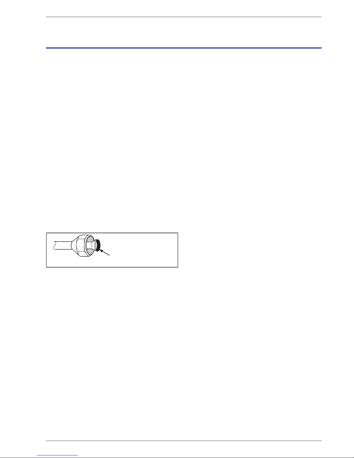
• Flared connections
" Lubricating with mineral oil (for R12, R22) is prohibited.
- Lubricate only with polyolester oil (POE). If POE is not
available, t without lubrication.
Coat the ared surface with POE
refrigeration oil.
Do not use mineral oil.
• Brazing the refrigeration circuit (if necessary)
- Silver brazing (40% minimum recommended).
- Brazing only with dry nitrogen internal ux.
• Other remarks
- After each maintenance operation on the refrigeration
circuit and before nal connection, take care to put
the caps back in position to avoid any pollution of the
refrigeration circuit.
- To eliminate any lings getting into the pipes, use dry
nitrogen to avoid introducing any humidity that may
adversely aect the appliance's operation. In general,
take every precaution to avoid humidity penetrating
into the appliance.
- Proceed with thermal insulation of the gas and liquid
pipes to avoid any condensation. Use pipe insulators
resistant to temperatures over 90°C. In addition, if the
humidity level in areas where the refrigerant pipes are
installed is expected to exceed 70%, protect the pipes
with pipe insulators. Use an insulating material thicker
than 15mm if the humidity level reaches 80%, and an
insulating material thicker than 20mm if the humidity
exceeds 80%. If the recommended thicknesses are
not observed under the conditions described above,
condensation will form on the surface of the insulation
material. Lastly, use insulating sleeves whose thermal
conductivity will be less than or equal to 0.045 W/mK if
the temperature is equal to 20°C. The insulation must
be impermeable in order to withstand the passage
of vapour during the defrosting cycles (glass wool is
prohibited).
3.2 Shaping the refrigeration pipes
3.2.1 Bending
The refrigeration pipes must be shaped only on a
bending machine or with a bending spring in order to
avoid any risk of crushing or breaking them.
" Warning!
• Remove the insulation material from the section of
pipe to be bent.
• Do not bend copper to an angle greater than 90°.
• Never bend pipes more than 3 times in the same place
otherwise traces of fracturing may appear (hardening
of the metal).
3 Refrigeration connections
and lling the installation with gas
Installation and Operating Manual "1873- EN" - 21 -
Alféa Extensa Duo A.I. Heat Pump
Page 22
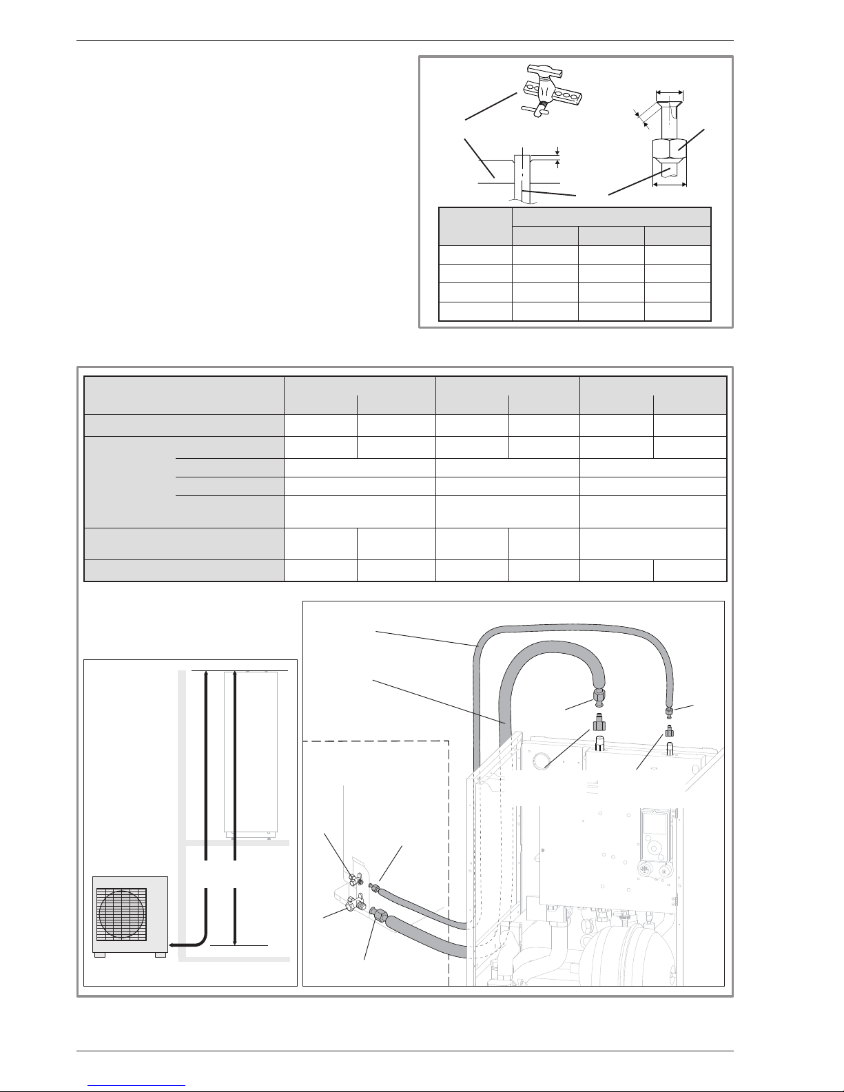
gure 19 - Refrigeration connections (authorised diameters and lengths)
HP model
Alféa Extensa Duo A.I. 5, 6 Alféa Extensa Duo A.I. 8 Alféa Extensa Duo A.I. 10
gas liquid gas liquid gas liquid
Outside unit connections 1/2" 1/4" 5/8" 1/4" 5/8" 3/8"
Refrigeration
connections
Diameter: (D1) 1/2" (D2) 1/4" (D1) 5/8" (D2) 1/4" (D1) 5/8" (D2) 3/8"
Minimum length (L) 5 5 5
Maximum length** (L) 30 30 30
Maximum Height
Difference** (D)
20 20 20
Male-female adapter
(reduction)
(R1)
1/2" - 5/8"
(R2)
1/4" - 3/8"
without
(R2)
1/4" - 3/8"
without
Hydraulic unit connections 5/8" 3/8" 5/8" 3/8" 5/8" 3/8"
**: Including any additional lling (see "Additional lling", page 27).
DL
Heat pump
Hydraulic unit
Heat Pump
Outdoor unit
"Gas" refrigeration
connection
diameter D1
"Liquid" refrigeration
connection
diameter D2
Flared
nut
Flared nut
R2 adapter
(depending on
model)
R1 adapter
(depending on
model)
Flared
nut
Flared
nut
"Liquid”
valve
“Gas”
valve
Hydraulic unit
Outdoor unit
gure 18 - Flaring of the ared connections
Flaring tool
Pipe
Nut
are
B
L
C
Pipe ø
Dimensions in mm
L B 0/
-0.4
C
6.35 (1/4") 1.8 to 2 9.1 17
9.52 (3/8") 2.5 to 2.7 13.2 22
12.7 (1/2") 2.6 to 2.9 16.6 26
15.88 (5/8") 2.9 to 3.1 19.7 29
3.2.2 Creating the arings
- Cut the pipe to an appropriate length with a pipe-cutter
without damaging it.
- Carefully deburr it, holding the pipe pointing downward
to avoid introducing lings into the pipe.
- Remove the ared connection nut situated on the
valve to be connected and slide the pipe into the nut.
- Proceed to are it, letting the pipe protrude out of the
aring tool's tube.
- After aring, check the state of the working radius (L).
This must not present any scratches or signs of
fracturing. Also check the dimension (B).
Installation and Operating Manual "1873- EN"
Alféa Extensa Duo A.I. Heat Pump
- 22 -
Page 23
3.3 Checks and connection
" The refrigeration circuit is very sensitive
to dust and humidity: check that the area
around the connection is clean and dry
before removing the plugs protecting the
refrigeration connectors.
" Indicated blowing value: 6 bar for minimum
30 seconds for connection of 20 m.
Checking the gas connection (large diameter).
Connect the gas connection to the outdoor unit.
Blow dry nitrogen into the gas connection and inspect
its end:
- If water or impurities emerge, use a brand new
refrigeration connection.
Otherwise, proceed with aring and connect the
refrigeration connection to the outdoor unit immediately.
Checking the liquid connection (small diameter).
Connect the liquid connection to the hydraulic unit.
Blow nitrogen into the gas-condenser-liquid connection
system and inspect its end (outdoor unit side).
- If water or impurities emerge, use a brand new
refrigeration connection.
- Otherwise, proceed with aring and connect the
refrigeration connection to the outdoor unit immediately.
" Take particular care to position the tube opposite
its connector so as not to risk damaging the
threads. A properly aligned connector can be
attached easily by hand without much force
being required.
- Where necessary, connect an adapter (reducer)
1/4''- 3/8'' or 1/2''- 5/8'' (see gure 19).
- Remove the plugs from the pipes and the refrigeration
connections.
- Comply with the indicated tightening torques.
gure 20 - Tightening torques
Designation Tightening torque
Flare 6.35 mm (1/4") 14 to 18 Nm
Flared nut 9.52 mm (3/8") 33 to 42 Nm
Flared nut 12.7 mm (1/2") 50 to 62 Nm
Flared nut 15.88 mm (5/8") 63 to 77 Nm
Plug (A) 3/8", 1/4" 20 to 25 Nm
Plug (A) 1/2" 25 to 30 Nm
Plug (A) 5/8" 30 to 35 Nm
Plug (B) 3/8", 5/8" 10 to 12 Nm
Plug (B) 1/2", 1/4" 12.5 to 16 Nm
Plug (A) and (B) : see gure 22, page 25.
Holding spanner
Torque wrench
gure 21 - Checking refrigeration connections
Nitrogen
Nitrogen
Nitrogen
Gas
connection
Gas
connection
Gas
Liquid
connection
Installation and Operating Manual "1873- EN" - 23 -
Alféa Extensa Duo A.I. Heat Pump
Page 24
3.4 Filling the installation with gas
" This operation is reserved for installers familiar with the legislation for handling refrigerants.
" Creating a vacuum with a calibrated vacuum pump is essential (see APPENDIX 1).
" Never use equipment used previously with any refrigerant other than a HFC.
" Only remove the refrigeration circuit caps when performing the refrigeration connections.
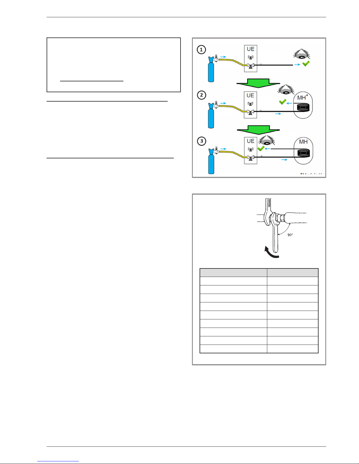
APPENDIX 2
Triple Evacuation Method
- Connect the Manifold high-pressure hose to the
lling hole (gas connection). A valve must be tted
to the vacuum pump's hose so you can shut it o.
a) Create a vacuum until the desired value is
reached and maintain this value for 30 mins
(see table in APPENDIX 1),
Lo
Hi
UE
MH
Liaison...
liquide
gaz
Haute
pression
Jeu de manomètres
(Manifold)
Basse
pression
Vacuomètre
Pompe à vide
Set of pressure gauges
(Manifold)
Low
Pressure
High
Pressure
Vacuum pump
Connection
Liquid
Gas
Vacuum
b) Switch o the vacuum pump, close the valve at
the end of the service hose (yellow), connect this
hose to the expansion valve on the nitrogen bottle,
ll to 2 bar, close the hose's valve again,
Lo
Hi
UE
MH
Liaison...
liquide
gaz
Haute
pression
Azote
High
Pressure
Nitrogen
Connection
Liquid
Gas
c) Connect this hose to the vacuum pump again,
switch it on and slowly open the hose's valve.
Lo
Hi
UE
MH
Liaison...
liquide
gaz
Haute
pression
High
Pressure
Connection
Liquid
Gas
d) Repeat this operation at least three times.
" Remember: performing these operations
using refrigerant is strictly prohibited.
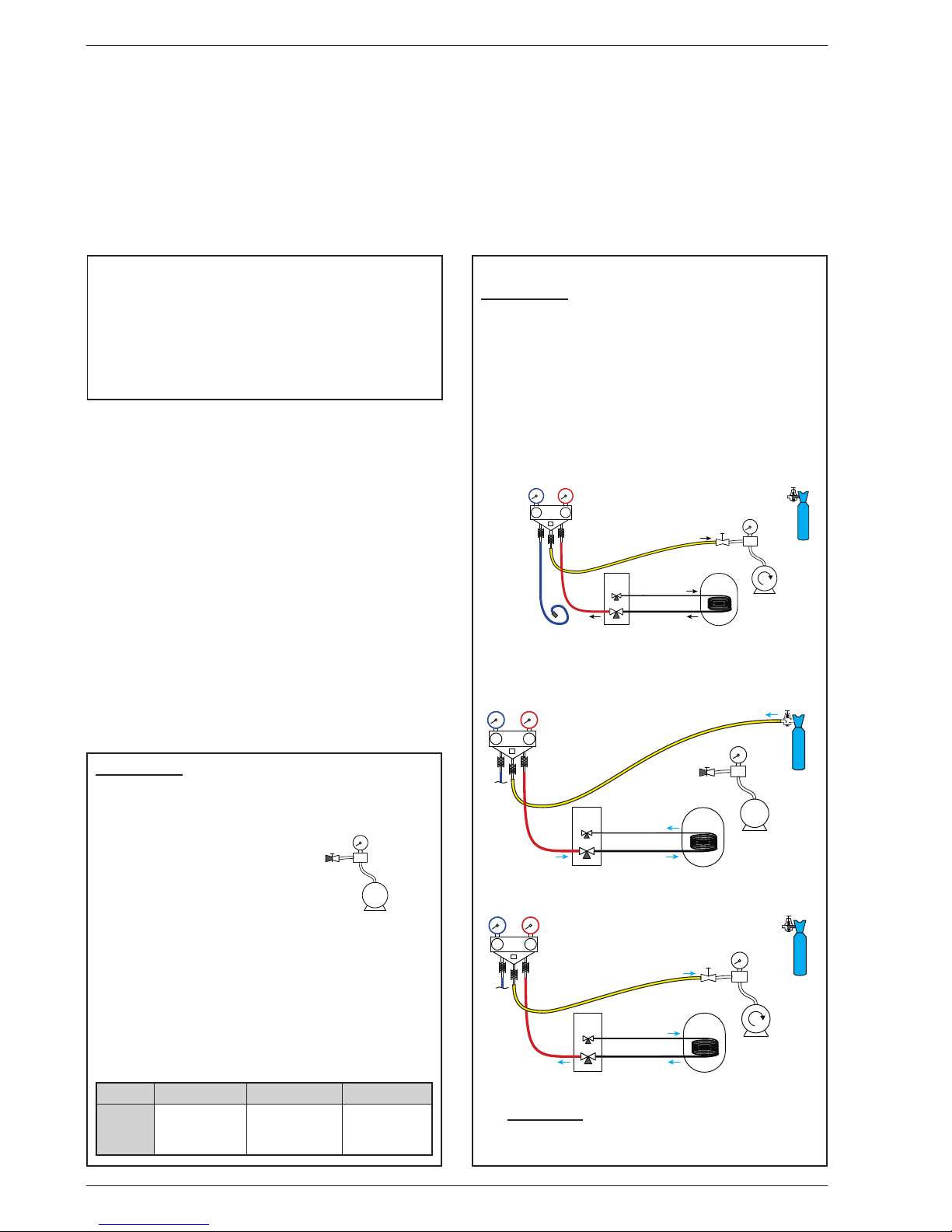
APPENDIX 1
Method for calibrating and checking a vacuum
pump
- Check the vacuum pump's oil level.
- Connect the vacuum pump
to the vacuum gauge as
shown in the diagram.
- Pump down for 3 minutes.
- After 3 minutes, the pump
reaches its threshold vacuum limit and the vacuum
gauge's needle stops moving.
- Compare the obtained pressure value against the
table of values. Depending on the temperature, this
pressure should be lower than that shown in the
table.
=> If this is not the case, replace the gasket, hose
or pump.
T °C 5°C<T<10°C 10°C<T<15°C 15°C < T
Pmax
- bar
- mbar
0.009
9
0.015
15
0.020
20
Vacuomètre
Flexible
bouché
Pompe
à vide
" If the outdoor temperature is below +10°C:
- You must use the triple evacuation method
(see APPENDIX 2).
- We recommend installing a dehydrator lter
(and this is highly recommended if the outdoor
temperature is below +5°C).
Gauge
Vacuum
gauge
Vacuum
pump
Plugged
hose
Installation and Operating Manual "1873- EN"
Alféa Extensa Duo A.I. Heat Pump
- 24 -
Page 25
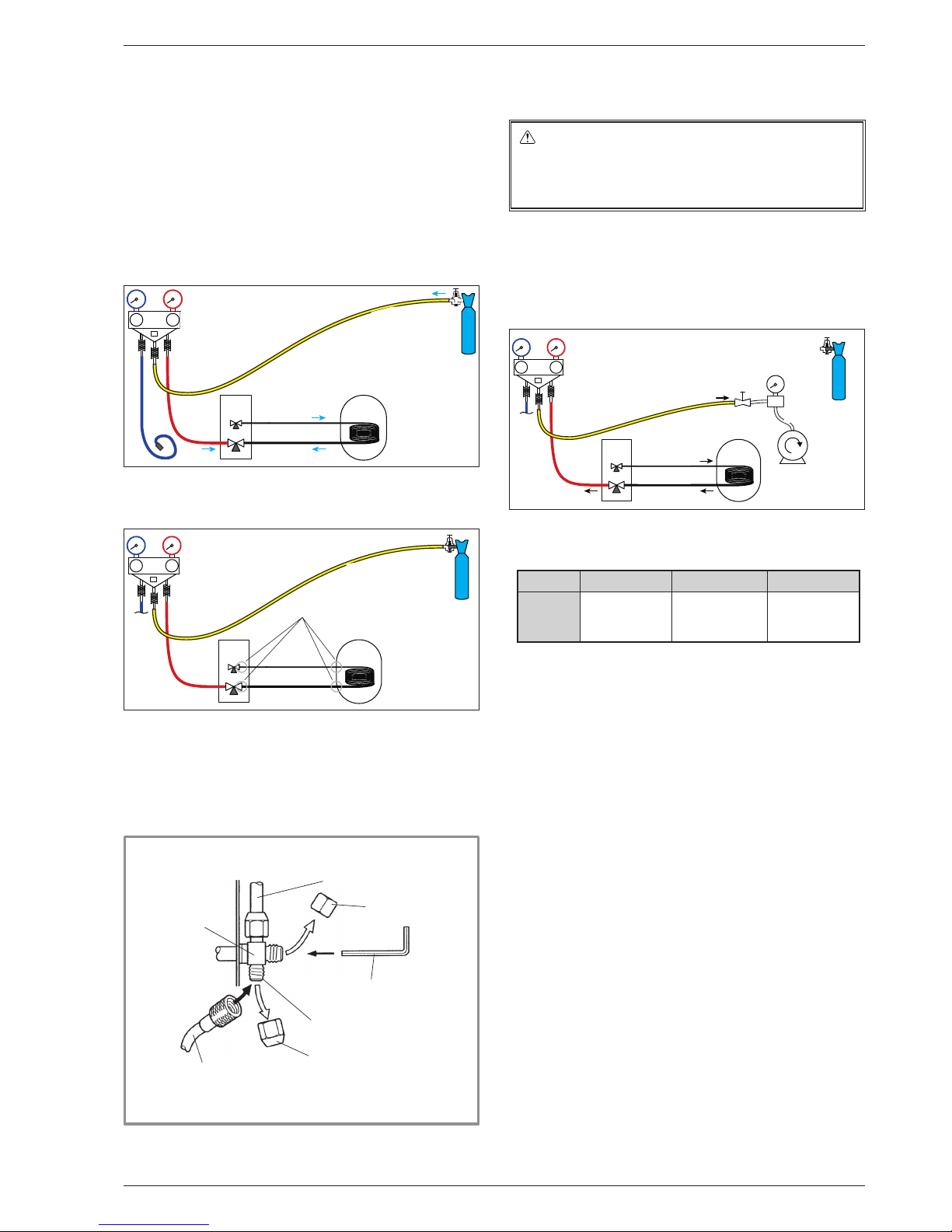
3.4.1 Seal test
- Remove the protective plug (B) from the lling hole
(Schrader) in the gas valve (large diameter).
- Connect the high pressure hose from the Manifold to
the lling hole (gure 22).
- Connect the nitrogen bottle to the Manifold (only use
dehydrated nitrogen type U).
- Fill the refrigeration circuit with nitrogen to maximum
10 bar (gas-condenser-liquid connection system).
- Maintain this pressure in the circuit for 30 minutes.
Lo
Hi
UE
MH
Liaison...
liquide
gaz
Haute
pression
Azote
10 bars max.
30 mn mini
- If a pressure drop occurs, bring it back down to 1 bar
and look for leaks with a leak detector, repair and
repeat the test.
Lo
Hi
UE
MH
Liaison...
liquide
gaz
Haute
pression
Contrôle
d’étanchéité
Vanne fermée,
Contrôle pression
- Once the pressure is steady and there are no leaks,
empty the nitrogen by leaving the pressure above
atmospheric pressure (between 0.2 and 0.4 bar).
3.4.2 Creating a vacuum
The triple evacuation method (APPENDIX 2)
is strongly recommended for any installation and
especially when the outdoor temperature is
below 10°C.
- If necessary, calibrate the manometers(s) of the
Manifold to 0 bar. Adjust the vacuum gauge to the
atmospheric pressure (≈ 1013 mbar).
- Connect the vacuum pump to the Manifold. Connect
a vacuum gauge if the vacuum pump is not equipped
with one.
Lo
Hi
UE
MH
Liaison...
liquide
gaz
Haute
pression
Vacuomètre
Pompe à vide
- Create a vacuum until the residual pressure* in the
circuit falls below the value given in the following
table (* measured with the vacuum gauge).
T °C 5°C<T<10°C 10°C<T<15°C 15°C < T
Pmax
- bar
- mbar
0.009
9
0.015
15
0.020
20
- Let the pump continue to operate for another 30 minutes
minimum after reaching the vacuum.
- Close the Manifold valve, then stop the vacuum pump
without disconnecting any of the hoses in place
Liaison frigorifique (gaz)
Bouchon (A)
Clé hexagonale/Allen
(4mm)
Vanne3voies
Orifice de charge
Bouchon (B)
Flexible haute pression
(rouge)
gure 22 - Connecting the hose to the gas valve
High
Pressure
Valve closed
Seal test
High
Pressure
Nitrogen
Max 10 bar
Min 30 mins
Connection
Liquid
Gas
High
Pressure
Vacuum pump
Connection
Liquid
Vacuum
Gauge
Gas
3-way valve
Refrigeration connection
(gas)
Plug (A)
Plug (B)
Filling hole
High-pressure hose (red)
Allen (hex) key (4 mm)
Installation and Operating Manual "1873- EN" - 25 -
Alféa Extensa Duo A.I. Heat Pump
Page 26

3.4.3 Filling with gas
If additional lling is required, do it before
lling the hydraulic unit with gas. Refer to
paragraph "Additional lling", page 27.
- Remove the access plugs (A) from the valve controls.
- First of all fully open the liquid valve (small) and
then the gas valve (large) using an Allen (hex) key
(anti-clockwise direction) without using excessive
force against the stop.
- Quickly disconnect the hose from the Manifold.
- Ret the 2 original caps (be sure they are clean) and
tighten them to the recommended tightening torque
indicated in the table gure 20, page 23. A seal is
achieved in the caps only with metal to metal.
The outdoor unit does not contain any additional
refrigerant allowing the installation to be bled.
Bleeding by ushing is strictly forbidden.
3.4.4 Final sealing test
The sealing test must be carried out with a certied gas
detector (sensitivity of 5g/year).
Once the refrigeration circuit has been gassed as
described above, check that all the refrigeration
connectors are gas-tight (4 connectors). If the arings
have been made correctly, there should be no leaks.
If necessary, check the seal of the refrigeration valve
caps.
" If the event of a leak:
- Return the gas to the outdoor unit (pump down).
The pressure should not drop below atmospheric
pressure (0 relative bar read on the Manifold) so as not
to contaminate the recovered gas with air or moisture.
- Redo the connection,
- Restart the commissioning procedure.
Installation and Operating Manual "1873- EN"
Alféa Extensa Duo A.I. Heat Pump
- 26 -
Page 27
3.4.5 Additional lling
The amount needed to ll the outdoor units corresponds to the maximum distances between the outdoor unit and the
hydraulic unit as dened here page 22. If the distances are greater, an additional amount of R410A is required.
For each type of appliance, this additional amount depends on the distance between the outdoor unit and the
hydraulic unit. Any additional lling with R410A must be carried out by an approved specialist.
Alféa Extensa Duo A.I. 5, 6, 8 (Outdoor unit WOYA060LFCA, WOYA080LFCA)
15m < Length of the connections ≤ 30m
(Length of the connections - 15 m) x 25 g/m = g
Model /
Factory ll
Length of the
connections in m
16 17 X 29 30
Alféa Extensa Duo A.I. 5, 6 /
1100 g
Fill amount in g
1125 1150 1100 + (X - 15) x 25 = g 1450 1475
Alféa Extensa Duo A.I. 8 /
1400 g
1425 1450 1400 + (X - 15) x 25 = g 1750 1775
Alféa Extensa Duo A.I. 10 (Outdoor unit WOYA100LFTA)
15m < Length of the connections ≤ 30m
(Length of the connections - 15 m) x 40 g/m = g
Model /
Factory ll
Length of the
connections in m
16 17 X 29 30
Alféa Extensa Duo A.I. 10 /
1800 g
Fill amount in g 1840 1880 1800 + (X - 15) x 40 = g 2360 2400
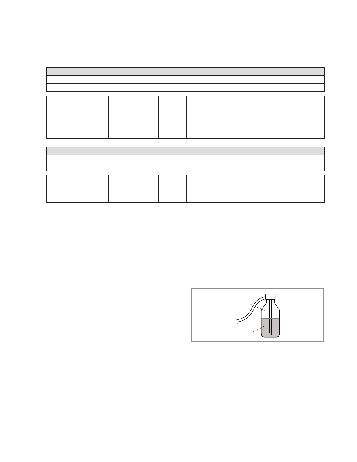
Filling must be carried out after creating a vacuum and
before gassing the hydraulic unit, as follows:
- Disconnect the vacuum pump (yellow hose) and
connect a bottle of R410A in its place in the uid
extraction position.
- Open the bottle’s valve.
- Bleed the yellow hose by loosening it slightly on the
Manifold side.
- Place the bottle on scales with a minimum accuracy of
10g. Note the weight.
- Carefully open the blue valve slightly and check the
value shown on the scales.
- As soon as the value displayed has dropped by the
value for the calculated additional ll amount, close the
bottle and disconnect it.
- Quickly disconnect the hose connected to the
appliance.
- Proceed to ll the hydraulic unit with gas.
R410A
Liquid
Gas
gure 23 - Gas bottle R410A
" Warning!
• Only use R410A!
• Only use tools suitable for R410A
(set of pressure gauges).
• Always ll in the liquid phase.
• Never exceed the maximum length or dierence in
level.
Installation and Operating Manual "1873- EN" - 27 -
Alféa Extensa Duo A.I. Heat Pump
Page 28

3.4.6 Recovering the refrigerant
in the outdoor unit
" Before performing any maintenance, make
sure that all power supplies have been cut o.
"
Stored energy: after cutting o the power
supplies, wait for 1 minute before accessing
the internal parts of the equipment.
Perform the following procedures to collect the
refrigerant.
- 1- Switch the start/stop switch to the 0 position
(mark 3, gure 9, page 13). Disconnect the outdoor
unit's power supply.
- 2- Remove the front panel. Open the power control
box. Then turn ON the DIP SW1 on the interface
board,
- 3- Reconnect the power supply. Switch
the start/stop switch to position 1.
(The green and red LEDs start ashing;
1s on / 1s o). The outdoor unit begins cooling
operation about 3 minutes after being switched on.
- 4- The circulation pump starts.
- 5- Close the liquid valve on the outdoor unit maximum
30 secs after the outdoor unit starts.
- 6- Close the gas valve on the outdoor unit when
the pressure is below 0.02 relative bar read on the
Manifold, or 1-2 minutes after the liquid valve has been
closed, while the outdoor unit continues to operate.
- 7- Disconnect the power supply.
- 8- Recovery of the refrigerant is complete.
Notes:
- The pump down operation cannot be activated even
if DIP SW1 is set to ON while the heat pump is in
operation.
- Do not forget to switch DIP SW1 back to OFF after
the pump down operation has been completed.
- Select the heating mode.
- If the pump down operation fails, try the
operation again by turning the machine o and
opening the "liquid" and "gas" valves. Then after
2-3 minutes, restart the pump down operation.
gure 24 - Location of DIP switches and LEDs
on the hydraulic unit interface board
DIP SW
Interface Board
LED2
(Green)
LED1
(Red)
OFF
ON
Installation and Operating Manual "1873- EN"
Alféa Extensa Duo A.I. Heat Pump
- 28 -
Page 29

Installation and Operating Manual "1873- EN" - 29 -
Alféa Extensa Duo A.I. Heat Pump
Page 30

4.1 Connecting the hydraulic unit
to the heating circuit
4.1.1 Flushing the installation
Before connecting the hydraulic unit to the installation,
rinse out the heating system correctly to eliminate
any particles that may aect the appliance's correct
operation.
Do not use solvents or aromatic hydrocarbons (petrol,
paran, etc.).
In the case of an old installation, provide a suciently
large decanting pot with a drain on the return from the
boiler and at the lowest point in the system in order to
collect and remove any impurities.
Add an alkaline product and a dispersant to the water.
Flush the installation several times before proceeding
to the nal lling.
4.1.2 Connections
The heating circulation pump is built into the hydraulic
unit.
Connect the central heating pipes to the hydraulic unit
correctly according to the direction of circulation.
The pipe between the hydraulic unit and the heat collector
must be at least one inch in diameter (26x34 mm).
Calculate the diameter of the pipes based on ow rates
and lengths of the hydraulic systems.
Tightening torque: 15 to 35 Nm.
Use union connectors to make it easier to remove the
hydraulic unit.
Try to use connection hoses to avoid transmitting noise
and vibrations to the building.
Connect the drains from the drain valve and the safety
valve to the main sewer system.
Verify that the expansion system is correctly connected.
Check the expansion vessel pressure (pre-inated to 1
bar) and the safety valve is calibrated.
The ow rate of the installation must be at least equal to
the minimum value mentioned in the specications table
(section 1.4, page 7). The installation of a regulator
(other than those included in our congurations) which
reduces or stops the ow through the hydraulic unit is
prohibited.
4 Hydraulic connections
Installation and Operating Manual "1873- EN"
Alféa Extensa Duo A.I. Heat Pump
- 30 -
Page 31

R1
D
MT
CAR
GS
gure 25 - Basic Hydraulic Layout
Key:
CAR: Non-return valve.
D: Shut-o.
GS: Safety valve (mandatory
/ not supplied).
MT: Thermostatic mixer valve.
R1: Heating circuit.
Ø 26x34
1" male
Ø 20x27
3/4" male
4.1.3 Volume of the heating system
You must maintain the minimum installation water
volume. Install a buer tank on the return from the
heating circuit in case the volume is lower than this
value. Where the system is tted with one or more
thermostatic valves, you must ensure that this minimum
water volume is able to circulate.
Min. volume in litres PER CIRCUIT (excl. HP)
Heat Pump
Mandatory
Fan-coil
Recommendation
Radiators
Recommendation
Heating-cooling oor
Alféa Extensa Duo A.I. 5 23 12 2
Alféa Extensa Duo A.I. 6 23 12 2
Alféa Extensa Duo A.I. 8 36 33 15
Alféa Extensa Duo A.I. 10 49 44 22
Installation and Operating Manual "1873- EN" - 31 -
Alféa Extensa Duo A.I. Heat Pump
Page 32

4.2 Connecting to the DHW circuit
Attach dielectric connections and DHW pipes to the tank
(see gure 26). Insulate the pipes with the insulation
provided.
" Be sure to place the DHW sensor back in the
bottom of the tank thermowell.
Mandatory: On the cold water inlet, place a safety valve
calibrated to between 7 and 10 bar max. (depending on
local regulations) and connected to a drain pipe leading
to the sewer. Operate the safety valve according to
manufacturer's specications. The domestic hot water
tank must be fed with cold water passing through a
safety valve. There must be no other valves between
the safety valve and the tank.
Connect the safety valve to the sewer.
We recommend installing a thermostatic mixing valve
on the hot water outlet.
DHW outlet on RHS of HP
DHW outlet on LHS of HP
DHW outlet on both sides of HP
55 mm
gure 26 - Attaching DHW pipe connections
40Nm
gure 27 - DHW circuit outlets
Installation and Operating Manual "1873- EN"
Alféa Extensa Duo A.I. Heat Pump
- 32 -
Page 33

1
2
3
5
4
6
7
8
9
10
11
Key:
1. "Liquid" refrigeration connection.
2. "Gas" refrigeration connection.
3. Heating return (1 circuit).
4. Heating ow (1 circuit).
5. Stop valve (not provided).
6. DHW outlet (domestic hot water).
7. DCW inlet (domestic cold water).
8. Shut-o (not provided).
9. Filling.
10. Safety valve (mandatory / not supplied).
11. Connections to sewer with siphon
(safety valve).
gure 28 - Connections
4.3 Filling and bleeding the installation
Check the pipe xings, tightness of the connectors and
the stability of the hydraulic unit.
Check the direction in which the water is circulating and
that all the valves are open.
Proceed to ll the installation.
Do not operate the circulation pump during lling. Open
all the drain valves in the installation and the bleeder
valve on the hydraulic unit (P) to expel the air contained
in the pipes.
Close the drain valves and add water until the pressure
in the hydraulic circuit reaches 1 bar.
Check that the hydraulic circuit has been bled correctly.
Check there are no leaks.
After the "Commissioning", page 42 stage, and once the
machine has started, bleed the hydraulic unit again
(2 litres of water).
" Precise lling pressure is determined by the
water pressure in the installation.
gure 29 - Hydraulic unit manual bleeder valve
P
Installation and Operating Manual "1873- EN" - 33 -
Alféa Extensa Duo A.I. Heat Pump
Page 34

4.4 Heating circulation pump
speed settings
gure 30 - Available hydraulic pressures and ow rates
gure 31 - Operating signals of the HP circulation pump
LED O:
The circulation pump is not working, no power supply.
Green LED On:
The circulation pump is operating normally.
Green LED ashing:
Venting mode in operation (10 minutes).
Red/green LED ashing:
Operating error with automatic restart.
Red LED ashing:
Operating error.
0
1
2
3
4
5
6
7
8
mCE
1 mbar=10 mmCE=100 Pa
m/h
3
1
1,5 20,50
1
3
55
77
0
1
2
3
4
5
6
7
8
mCE
1 mbar=10 mmCE=100 Pa
m/h
3
1
1,5 20,50
1
3
55
77
Variable pressure
The circulation pump varies the water
pressure depending on the ow rate.
Recommended for an installation tted with
radiators (particularly any system with
thermostatic valves or zone solenoids).
Constant pressure
The circulation pump maintains a constant
water pressure whatever the ow rate.
Recommended for an installation with
constant pressure drops such as an
underoor heating system.
Ne pas utiliser cette zone
Do not use these zones
Installation and Operating Manual "1873- EN"
Alféa Extensa Duo A.I. Heat Pump
- 34 -
Page 35

Circulation pump fouled or stuck:
If the motor becomes stuck, a start-up cycle is launched.
If the motor remains stuck, it will be permanently
stopped.
" Cut o the power supply to the circulation pump
for 30 secs in order to free it and allow a new
start-up cycle to begin.
gure 32 - Circulation pump control button
Pression variable
Dégazage
Pression constate
Variable pressure
Gas venting
Constant pressure
Installation and Operating Manual "1873- EN" - 35 -
Alféa Extensa Duo A.I. Heat Pump
Page 36

" Before any maintenance operation, ensure that the general power supply is switched o.
" Electrical installation must be performed in accordance with current regulations.
5 Electrical connections
The electrical diagram for the hydraulic unit is shown on gure 48, page 73.
gure 33 - Overall layout of electrical connections for a simple installation (1 heating circuit)
Outside sensor
Cable 2 x 0.75 mm²
Connection outdoor unit and hydraulic unit
(phase, neutral, earth, communications bus)
Cable 4 x 1.5 mm²
Room sensor A78 (battery/option)
Room sensor A59 (battery/option)
Room sensor A75 (option)
Cable 2 x 0.5 mm²
Room sensor A59 (option)
Cable 2 x 0.5 mm²
Typass ATL (option)
Cable 3 x 0.5 mm²
Electrical backup power supply (option)
(see table below)
DHW power supply
(phase, neutral, earth) Cable 3 x 1.5 mm²
General electrical supply (phase, neutral, earth)
(see table below)
Electrical
Board
or
or
or
or
Installation and Operating Manual "1873- EN"
Alféa Extensa Duo A.I. Heat Pump
- 36 -
Page 37

5.1 Cable dimensions and protection rating
These cable dimensions are provided for information purposes only and do not exempt the installer from checking
that these dimensions match requirements and comply with current standards.
• Outdoor Unit Power Supply
Heat Pump (HP) Electricity supply 230 V - 50 Hz
Model
Max. power
consumption
Connection cable
(phase, neutral, earth)
Circuit breaker
C curve
Alféa Extensa Duo A.I. 5 2530 W
3 x 1.5 mm² 16 A
Alféa Extensa Duo A.I. 6 2875 W
Alféa Extensa Duo A.I. 8 4025 W
3 x 2.5 mm² 20 A
Alféa Extensa Duo A.I. 10 4255 W
• Interconnection between outdoor unit and hydraulic unit
The hydraulic unit is powered by the outdoor unit by means of a 4 x 1.5 mm² cable
(phase, neutral, earth, communication bus).
• DHW power supply
The DHW section is powered directly via a 3 x 1.5 mm² cable (phase, neutral, earth).
Protection by circuit breaker (16 A, C curve).
• Electrical backup power supply (option)
The hydraulic unit contains a electrical backup circuit (option) installed in the storage tank.
Heat pump Electrical backups Electrical backup power supply
Model Power Nominal current
Cable
(phase, neutral, earth)
Circuit breaker
C curve
Alféa Extensa Duo A.I.
5, 6, 8 and 10
with 6 kW Backup Kit
2 x 3 kW 26.1 A 3 x 6 mm² 32 A
Installation and Operating Manual "1873- EN" - 37 -
Alféa Extensa Duo A.I. Heat Pump
Page 38

5.2 Electrical connections
on the outdoor unit side
Access to connection terminals:
• Alféa Extensa Duo A.I. models 5, 6 and 8
- Remove the cowl.
• Alféa Extensa Duo A.I. model 10
- Remove the front panel and cowl.
- Make the connections according to the diagram (gure 34).
- Use cable clamps to prevent any power cables from
being disconnected accidentally.
- Fill in the space where the cables enter the outdoor
unit with the insulating plate.
Remove the cap
(1 screw)
Brackets (4 places)
Remove the
front panel
(2 screws)
Bracket
(3 places)
Déposer le capot
(2 vis)
Crochets
(4 endroits)
Câbles
Serre-Câble
Hooks
(x3)
Hooks (x4)
Remove the cowl
(1 screw)
Remove the front panel
(2 screws)
gure 34 - Connections to outdoor unit's terminal block gure 35 - Access to outdoor unit's terminal block
Hooks
(4 places)
Cable clamp
Cable
Remove the cowl
(2 screws)
General power cable
Interconnection
between outdoor unit
and hydraulic unit
Terminal
Installation and Operating Manual "1873- EN"
Alféa Extensa Duo A.I. Heat Pump
- 38 -
" Alféa Extensa Duo A.I. 5, 6 and 8
" Alféa Extensa Duo A.I. 10
Page 39

5.3 Electrical connections
on the hydraulic unit side
Access to connection terminals:
- Remove the front plate.
- Open the power control box.
- Make the connections according to the diagram (gure 37).
Do not place the sensor and power supply lines parallel
to each other to avoid interference due to voltage spikes
in the power supply.
Make sure that all electrical cables are housed in the
areas provided for this purpose.
• Interconnection between outdoor unit and
hydraulic unit
Match up the terminal block markers on the hydraulic
unit to those of the outdoor unit exactly when connecting
the interconnection cables.
An incorrect connection could result in the destruction
of one or other of the units.
• Electrical backup (option)
If the heat pump is not installed with a boiler connection:
- Connect the power supply for the backup to the
electrical panel.
• Boiler connection (option)
" If the boiler connection option is used, the
electric backup option must not be connected.
- Please refer to the instructions supplied with the boiler
connection kit.
- Please refer to the instructions supplied with the boiler.
• Second heating circuit (option)
- Refer to the instructions supplied with the double
hydraulic circuit kit.
• Contract with Energy Supplier
The heat pump can be set to operate within particular
types of energy contract, e.g. o-peak, day/night.
In particular, domestic hot water (DHW) at the comfort
temperature will be produced at o-peak times when
electricity is at its cheapest.
- Connect the "energy supplier" to the EX2 input.
- Set the DHW conguration to "O-Peak".
• 230V on input EX2 = "Peak Hours” information
activated.
• Power limitation or EDR (Energy Demand
Reduction)
Power limitation is designed to reduce electricity
consumption when it is too high for the contract signed
with the energy supplier.
- Connect the power limiter device to input EX1. Heat
pump and DHW backups will be shut o in the event
of over-consumption by the dwelling.
• 230 V on input EX1 = power limitation in progress
• Faults external to the heat pump
Any component which reports back information
(Underoor heating safety switch, thermostat, pressure
switch, etc.) may signal an external problem and stop
the heat pump.
- Connect the external component to input EX3.
• 230 V on input EX3 = heat pump stopped
(system displays Error 369).
gure 36 - Description of the hydraulic module's electrical control box
HP controller
Cable grommets (power)
Interface Board
Cable grommets (sensors)
DHW Relay + Terminal
Terminal
Installation and Operating Manual "1873- EN" - 39 -
Alféa Extensa Duo A.I. Heat Pump
Page 40

5.4 Outside sensor
The outside sensor is required for correct operation of
the heat pump.
Please see the tting instructions on the sensor’s
packaging.
Place the sensor on the coldest side of the building,
generally the northern or north-western side.
It must not be exposed to morning sun.
It must be installed so as to be easily accessible but at
least 2.5m from the ground.
It is essential that it is not placed near any sources of
heat such as ues, upper parts of doors and windows,
near extractor vents, under balconies and eaves,
or anywhere which would insulate the sensor from
variations in the outdoor air temperature.
- Connect the outside sensor to connector X84
(terminals M and B9) on the heat pump control board.
5.5 Room sensor (option)
The room sensor is optional.
Please see the tting instructions on the sensor’s
packaging.
The sensor must be installed in the living room area on
an unobstructed wall. It must be installed so as to be
easily accessible.
Avoid direct sources of heat (chimney, television,
cooking surfaces, sun) and draughty areas (ventilation,
door, etc.).
Draughts in buildings are often brought about by cold air
blowing through the electrical ducting. Lag the electrical
ducts if there is a cold draught behind the room sensor.
5.5.1 Installing a room sensor
• Room sensor A59
- Connect the sensor's power supply to connector X86
on the HP control board using the connector provided
(terminals 2 and 3).
• Room sensor A75
- Connect the sensor's power supply to connector X86
on the HP control board using the connector provided
(terminals 2 and 3).
5.5.2 Installing a Typass ATL
- Connect the Typass ATL to connector X86
on the HP control board using the connector provided
(terminals 1, 2 and 3).
5.5.3 Fan convector zone
If the installation is equipped with fan convectors or
dynamic radiators, do not use a room sensor.
gure 37 - Connection to terminal blocks and power relay
230 V
L
N
L N
2
4
L
N
1 2 3
4 5 6 7
1
2
3
4
5
L
N
COM
L
1 2 3 L N
L
N
Outdoor unitHydraulic unit
Power supply
230 V
Power supply
Domestic Hot Water
230 V
towards external
component
contact*
red
blue
brown
green/yellow
Interconnection
between outdoor unit
and hydraulic unit
Installation and Operating Manual "1873- EN"
Alféa Extensa Duo A.I. Heat Pump
- 40 -
Page 41

23 1
X86 X84
X11
External component contact*
(faults, power limiter, electricity meter)
Outside
sensor
** Typass ATL
** Room sensor A75
** Room sensor A59
(if cabled)
or
Power limitation or
EDR
(Energy Demand Reduction)
Taris, peak times/o-
peak times, day/night
External fault
gure 38 - Connections on the heat pump controller (accessories and options)
** If the control device does not provide a potential-free contact, the contact must be relayed to create an equivalent wiring.
In any case, refer to the instructions for the external components (power limiting device, electricity meter, etc.) to create the wiring.
** Option
EX1
X86 X84
X11
EX2
EX3
External component contact*
(faults, power limiter, electricity meter)
Outside
sensor
Typass ATL
Room sensor A75
Room sensor A59
gure 39 - Sensor cable feeds
Power limitation or
EDR
(Energy Demand Reduction)
Taris, peak times/o-
peak times, day/night
External fault
Installation and Operating Manual "1873- EN" - 41 -
Alféa Extensa Duo A.I. Heat Pump
Page 42

6 Commissioning
- Close the installation's main circuit breaker.
Upon initial start-up (or in winter), to preheat the
compressor, engage the installation's main circuit
breaker (outdoor unit power supply) several
hours before starting any tests.
- Press the heat pump's Start/Stop button.
To ensure that inputs EX1, EX2 and EX3 operate
correctly: Check that the electricity supply's
neutral phase polarity has been respected.
When the power is switched on and every time that the
ON/OFF button is switched o and then switched on
again, the outdoor unit will take approximately 4 minutes
to start up, even if the setting is requesting heating.
When the power is switched on, the "Easy Start" quick start function allows you to set the appliance's initial settings.
- Turn the knob to choose the language.
- Press the knob to accept.
Easy Start
English
- Turn the knob to adjust the date. Press the knob to accept.
- Repeat this operation for the month, year, hours and minutes.
Easy Start
09: 45
Monday September
12
2016
- Set the appliance's power.
Easy Start
Alféa ---
-- KW
- Set the Electrical backup power:
3kW / 6kW / 9kW / None.
3 KW
Electrical back-up
Easy Start
Installation and Operating Manual "1873- EN"
Alféa Extensa Duo A.I. Heat Pump
- 42 -
Page 43

- If the installation covers 2 zones, set "2nd circuit kit" to "Yes".
2nd circuit kit
No
Easy Start
- Choose the radiator type for each zone:
Low temp. radiator / Heat. oor system / Dynamic Radiators / Radiators.
Low temp. radiator
Easy Start
Emitters type
Area 1 (Direct circuit)
- If the installation is tted with cooling function, choose the zone(s):
None / Area 1 / Area 2 / Area 1 and 2.
No
Cooling
Easy Start
- Appliance settings summary screen. Press the knob to accept.
- The appliance starts initialising.
Alféa xxxxxxxxx
x KW
Area 1 Low temp. radiator
3 KWElectrical back-up
No2nd circuit kit
Cooling Area 1
Easy Start
Validate
- The welcome screen is displayed (screen varies depending on installed options).
15:23
12°
19,0°
21,5
ECO
OFF
7 September 2017
Upon commissioning, the electrical backup heaters or boiler are liable to start up even if the outdoor temperature at
the time is above the heaters’ trigger temperature.
The controller uses the initial average outdoor temperature of 0°C and needs time to update this temperature.
Installation and Operating Manual "1873- EN" - 43 -
Alféa Extensa Duo A.I. Heat Pump
Page 44

N° Description
1
Menu button
2
Navigation knob (rotate knob), accept (press knob)
3
Back button
7 Controller Interface
7.1 User Interface
MENU
15:23
12°
19,0°
19.5
ECO
19,0°
21.5
ECO
OFF
" 2 heating circuit version
+ domestic hot water (DHW)
Zone 1 Zone 2
MENU
15:23
12°
19,0°
21,5
ECO
OFF
" 1 heating Circuit version
+ domestic hot water (DHW)
1
2
3
7 September 2017 7 September 2017
Installation and Operating Manual "1873- EN"
Alféa Extensa Duo A.I. Heat Pump
- 44 -
Page 45

7.2 Display Description
N° Symbols Denitions
1 15:23 Time
2
7 September 2017
Date
3
21.5
Temperature measured by the room
sensor*
4
19,0°
Room temperature setpoint
5
Information (Area names, emergency mode,
test mode, error display, etc.)
6
Domestic Hot Water (DHW):
Activated
Boosting in progress
Deactivated
7
Temperature measured by the
outside sensor
8
Operation
Heating
Cooling*
N° Symbols Denitions
9
Mode
Comfort
Manual (exemption)
ECO
Holiday
Floor drying
Stop (except frost)
10
Production via ...
Heat Pump
Electrical backup*
HP + electrical backup*
HP + Fuel/Gas*
Fuel/Gas*
* Option
15:23
12°
19,0°
19.5
ECO
19,0°
21.5
ECO
7
10
9
3
10
8
6
4
5
7 September 2017
Zone 1 Zone 2
1 2
Installation and Operating Manual "1873- EN" - 45 -
Alféa Extensa Duo A.I. Heat Pump
Page 46

7.3 Installer Menu
To access the Installer Menu, press and hold the
MENU
button and turn the knob a quarter turn to the right.
To return to the User Menu, repeat the same operation.
7.4 Navigating the Menus
To ... Action:
Access the menu
Press
MENU
.
Choose a menu item
Turn the knob to highlight your choice.
Press the knob to accept.
Return to the previous menu
Press .
Return to the main menu
Press
MENU
twice.
Return to the welcome screen
Press
MENU
or on the main menu.
Note: Some settings (or menus) might not be displayed. They are dependent on the installation's conguration
(and installed options).
gure 40 - Installer Menu
MENU
Installation and Operating Manual "1873- EN"
Alféa Extensa Duo A.I. Heat Pump
- 46 -
Page 47

7.5 Modifying Settings
• Turn the knob to highlight the setting you wish to
change.
• Press the knob to accept the change.
• Turn the knob to adjust the setting.
• Press the knob to accept your choice.
gure 41 - Navigation
MENU
MENU
HP conguration
System status
Auxiliary functions
Hydraulic conguration
Settings
Easy Start
Installed options
Installation and Operating Manual "1873- EN" - 47 -
Alféa Extensa Duo A.I. Heat Pump
Page 48

7.6 Temperature control
The heat pump's operation is subject to the temperature
control.
The heating circuit water temperature setpoint is
adjusted according to the outdoor temperature.
If there are thermostatic valves on the installation,
these must be fully open or set higher than the normal
temperature setpoint.
7.6.1 Setting
During the installation, the temperature control must be
congured to suit the radiators and level of insulation of
the dwelling.
The temperature control graphs (gure 42) refer to a
room temperature setpoint of 20°C.
The temperature control's gradient determines the
impact of variations in the outdoor temperature on
variations in the heating ow temperature.
The steeper the gradient, the more likely a slight
reduction in the outdoor temperature will cause a
signicant increase in the water ow temperature in the
heating circuit.
The temperature control o-set modies the ow
temperature of all graphs, without modifying the gradient
(gure 43).
Corrective actions to take in the case of discomfort are
listed in the table (gure 44).
Installation and Operating Manual "1873- EN"
Alféa Extensa Duo A.I. Heat Pump
- 48 -
Page 49

&
&
&
&
&
&
&
&
&
Sensations...
...in mild weather
...in cold weather Gradient O-set
No correction
No correction
No correction
No correction
No correction
Good Good
Good
Good
Good
Good
Cold
Cold
Cold Cold
Cold
Hot
Hot
Hot
Hot
Hot
Hot
Cold
No correction
Corrective actions on the temperature control:
gure 44 - Corrective actions in case of discomfort
gure 42 - Heating curve gradient
gure 43 - Transferral of the heating curve
40
50
60
70
-20-15-10
-55
10
-4,5
+4,5
20
0
10
30
0
30
Heating ow
temperature°C
External temperature °C
Curve o-set
Heating curve
gradient
0.5
90
80
70
60
50
55
40
30
° C
100
° C
20
-20
10
1
0.75
1.75
0.5
0.25
1.25
-100
2
1.5
2.753
2.25
2.5
Application relève de chaudière
Application PAC seule
Pente de la
courbe de chauffe
Radiateur classique
Radiateur dynamique
Radiateur BT
(basse température)
Plancher chauffant
T
empérature départ chau
ffage °C
Température extérieure °C
Heating curve gradient
Standard radiator
Low temperature radiator
Dynamic radiators
With boiler connection
Heat pump application only
Heating ow temperature
Underoor heating
Outdoor temperature
Installation and Operating Manual "1873- EN" - 49 -
Alféa Extensa Duo A.I. Heat Pump
Page 50

8 Controller Menu
8.1 Menu Structure
Some settings (or menus) might not be displayed. They are dependent on the installation's conguration (and installed options).
Installed options
page 51
Hydraulic conguration
Heating Control / Temperature control Temperature control
page 51 Comfort optimisation
ECO mode limitation
Setting setpoint T°
Time programming
DHW General Conguration
Time programming
Setting setpoint T°
Anti-legionella management
HP conguration
HP Compressor conguration
page 56 Heating/cooling conguration
DHW conguration
Tari input conguration
Electrical backup / Connection boiler
System status
Active functions
page 58 Control panel
Errors history
Temperature control
Energy consumption
Auxiliary functions
Floor drying
page 60 Emergency mode
Relay test
Outd. T° simulation
Reset factory conguration
Settings
Date and time
page 62 Language
Advanced/simplied menu
Areas name
Connectivities Connection
Reset connectivities
Software version
Easy Start
page 66
Installation and Operating Manual "1873- EN"
Alféa Extensa Duo A.I. Heat Pump
- 50 -
Page 51

8.2 Installed options
Installed options are congured during commissioning (see page 42). However, you
can modify them by accessing the "Installed Options" menu.
Name of Appliance
- Choose the appliance's power.
Electrical backup
- Choose the electrical backup power.
Boiler connection
-
If the electrical backup is set to "No", you can then set the boiler connection to "Yes ".
- If a power setting is applied to the electrical backup, the boiler connection setting
remains set to "No" and cannot be changed.
Number of Circuits
- Choose the number of circuits.
Cooling
- If the installation is tted with cooling function, choose the zone(s):
None / Area 1 / Area 2 / Area 1 and 2.
Name of Appliance
-- KW
Number of circuits 2
3 KWElectrical back-up
Area 1Cooling
Boiler connection No
Installed options
Complete
8.3 Hydraulic conguration
8.3.1 Heating / Cooling
- Choose the heating zone to congure.
Hydraulic conguration
Area 1 (Direct circuit)
Area 2 (Mixed circuit)
Hot water
Some settings (or menus) might not be displayed. They are dependent on the installation's conguration (and installed options).
Installed options
Hydraulic conguration Area 1
Installation and Operating Manual "1873- EN" - 51 -
Alféa Extensa Duo A.I. Heat Pump
Page 52

" Choose the temperature control to adjust: "Heating".
" Two methods for adjusting the temperature control are available: ow temperature or gradient control.
● Control using ow temperature
1
- Set "Room T° inuence" then select "Advanced settings".
2
- Set "Display" to "ow T°". Set "ow T° to -10°C" and "ow T° to +20°C".
3
- Set "Max ow T°" and "Min ow T°".
1
Area 1 Heating
Room T° inuence
Outd. T°
20-10
65
40%
ow T°
Advanced settings
15
ow T° at -10°C 47°C
2
Display
ow T°
ow T° at -10°C
ow T° at +20°C
47°C
22°C
Area 1 Heating
Outd. T°20-10
15
65
ow T°
Next
3
Max ow T°
Min ow T°
Outd. T°
20
-10
15
65
55°C
17°C
ow T°
Complete
Area 1 Heating
● Control using gradient
1
- Set "Room T° inuence" then select "Advanced settings".
2
- Set "Display" to "Gradient". Set "Gradient" and "O-set".
3
- Set "Max ow T°" and "Min ow T°".
1
Area 1 Heating
Room T° inuence
Outd. T°
20-10
65
40%
ow T°
Advanced settings
15
ow T° at -10°C 47°C
2
Display
Gradient
Gradient
Off-set
1
0°C
Area 1 Heating
Outd. T°20-10
15
65
ow T°
Next
3
Max ow T°
Min ow T°
Outd. T°20-10
15
65
55°C
17°C
ow T°
Complete
Area 1 Heating
● Use 100% ambient temperature
If set to use 100%, adjust the radiator type.
Room T° inuence
Emitters type
100%
Radiator
Area 1 Heating
Max ow T°
Min ow T°
55°C
17°C
Some settings (or menus) might not be displayed. They are dependent on the installation's conguration (and installed options).
Control / Temperature control
Temperature control
Hydraulic conguration Area 1
Installation and Operating Manual "1873- EN"
Alféa Extensa Duo A.I. Heat Pump
- 52 -
Page 53

"Accelerated decrease": ON / Stop.
"ECO / Comfort switchover" Anticipates time needed to reach the comfort setpoint.
"Comfort / ECO switchover" Anticipates time needed to switch from comfort setpoint
to ECO setpoint.
Area 1
Comfort optimisation
Accelerated decrease
Max anticipation
ECO / Comfort switchover
Comfort / ECO switchover
Stop
03:00 h
00:30 h
"Activation outd. T°": -30°C / +10°C.
"Stoping outd. T°": -30°C / +10°C.
Area 1
ECO mode limitation
Activation outd. T°
Stoping outd. T°
---
-5°C
"Comfort T°": ECO Temperature … 35°C.
"ECO T°": Holiday Temperature ... Comfort Temperature.
"Absence T°": 4°C… ECO Temperature.
" Heating temperatures factory settings:
Comfort 20°C, ECO 19°C, Absence 8°C.
" Cooling temperatures factory settings:
Comfort 24°C, ECO 26°C, Absence 35°C
Zone 1
Comfort T°
20°C
ECO T° 19°C
Absence T° 8°C
Heating Setpoint T°
Some settings (or menus) might not be displayed. They are dependent on the installation's conguration (and installed options).
Comfort optimisation
Control / Temperature control
ECO mode limitation
Setting setpoint T°
Hydraulic conguration
Hydraulic conguration
Area 1
Area 1
Installation and Operating Manual "1873- EN" - 53 -
Alféa Extensa Duo A.I. Heat Pump
Page 54

1
- Choose "Heating" or "Cooling" as well as the appropriate zone by accessing the menu:
"Programming" > "Heating" / "Cooling" > "Area 1" / "Area 2".
2
- Select the day.
3
- Adjust the Comfort period start and end times.
" If 2 or 3 Comfort periods are not required, click on "--:--".
- To return to the previous setting (e.g. end 1st heating period to start of 1st heating period), press the button.
• To copy the program to other days:
4
- Select "Validate and copy".
5
- Set the required days to "Yes" and then select "Complete".
• Else "Validate".
" Heating / cooling period factory setting: 06:00 - 22:00.
2
0 6 12 18 24
Heating prog.
Tuesday
Monday
Wednesday
Thursday
Friday
Saturday
Sunday
3
0 6 12 18 24
Monday
Comfort ranges
Validate
Validate and copy
Program 2: 11:45 14:00-
Program 3: --:-- --:---
Program 1: 06:50
07:50-
5
Copying programs
Copy the Mon. program to
Complete
NoWednesday
NoThursday
NoFriday
NoSaturday
NoSunday
Tuesday
Yes
To delete a Comfort period, set its start and end times to the same value.
When accepting a setting, the screen displays:
Program X: --:-- --:---
0 6 12 18 24
Monday
Comfort ranges
Validate and copy
Validate
Program 3: 18:30 23:00-
Program 1: 06:50 07:50-
Program 2:
--:-- --:---
Some settings (or menus) might not be displayed. They are dependent on the installation's conguration (and installed options).
Time programming
Hydraulic conguration Area 1
Installation and Operating Manual "1873- EN"
Alféa Extensa Duo A.I. Heat Pump
- 54 -
Page 55

8.3.2 Hot Water (HW)
"Comfort T° charge": DHW program + o-peak hours / O-peak hours / Permanent.
Electrical back-up power: 0 to 20 KW.
Conguration
Comfort T° charge
Electrical back-up power
1KW
DHW Circuit
DHW program + o-peak hours
See "Time programming", page 54.
" DHW period factory setting: 00:00 - 05:00, 14:30 - 17:00.
"Comfort T°": ECO Temp Setpoint … 65°C.
"ECO T°": 8°C... Comfort Temp setpoint.
" DHW temperature factory settings: Comfort 55°C, ECO 40°C.
Setpoint settings
Comfort T°
55°C
ECO T° 40°C
DHW Circuit
"Anti-legionella": Stop, ON.
"Day of treatment": Monday / Tuesday / Wednesday / Thursday / Friday / Saturday /
Sunday.
"Hour of treatment": 00:00.
"Setpoint T°": 55°C... 95°C.
Anti-legionella management
Day of treatment Sunday
Anti-legionella
Stop
Hour of treatment ---
Setpoint T° 60°C
DHW Circuit
Some settings (or menus) might not be displayed. They are dependent on the installation's conguration (and installed options).
Hydraulic conguration Hot water
General Conguration
Time programming
Setting setpoint T°
Anti-legionella management
Installation and Operating Manual "1873- EN" - 55 -
Alféa Extensa Duo A.I. Heat Pump
Page 56

8.4 Heat Pump Conguration
8.4.1 Heat Pump
"Minimum shutdown time": 0 mins... 120 mins.
"Max HP T°": 8°C... 100°C.
"Post-circulation": 10 secs... 600 secs.
"Power shedding operating": Automatic, When needed.
Released: HP = Start / DHW Backup = Stop / 1st HP Backup = Stop /
2nd HP Backup = Stop / Boiler = Start.
When needed (Locked): HP = Stop / DHW Backup = Stop /
1st HP Backup = Stop / 2nd HP Backup = Stop / Boiler = Start.
HP
Compressor conguration
Minimum shutdown time
8 mins
Post-circulation 240s
Max HP T° 75°C
Power shedding
operating
Released
1
- "Summer/winter switchover outd.T°" Zone 1: 8°C... 30°C.
"Mini. cooling switchover outd. T°": 8°C... 35°C.
"Mini. time prior to heat./cool.switchover ": 8h... 100h.
2
- "Circuit 2 heating": 0°C... 20°C.
- "Circuit 2 cooling": 0°C... 20°C.
1
HP
Heating/cooling conguration
Summer/winter switchover
outd.T°
18°C
Mini. cooling switchover
outd. T°
---
Mini. time prior to heat./
cool.switchover
24h
Next
2
HP
Complete
Heating/cooling conguration
Mixing valve compensation
Area 2
Area 2 heating 0°C
Area 2 cooling 0°C
"Maximum HP DHW T°": 0°C... 80°C.
"Switching dierential": 0°C... 20°C.
"Heat./cool. alternating time": 10 mins... 600 mins.
(with dynamic radiator, set to 40 mins).
HP
DHW conguration
Maximum HP DHW T°
52°C
Switching differential 7°C
Heat./cool. alternating time
90 mins
Some settings (or menus) might not be displayed. They are dependent on the installation's conguration (and installed options).
HP conguration HP
Compressor conguration
Heating/cooling conguration
DHW conguration
Installation and Operating Manual "1873- EN"
Alféa Extensa Duo A.I. Heat Pump
- 56 -
Page 57

"Type of use": Power shedding + O-peak hours / Smartgrid.
"EX1: function activation": 230V / 0V.
"EX2: function activation": 230V / 0V.
Heat Pump
Tari input conguration
EX1: function activation
230V
EX2: function activation
0V
Type of use
Power shedding +
Off-peak hours
8.4.2 Electrical back-up
"Authorisation if outd. T° <": -50°C... 50°C.
"Switching setting": 0°Cmin... 500°Cmin.
Conguration
Back-up
Switching setting
100°C min
Authorisation if outd. T° <
2°C
Some settings (or menus) might not be displayed. They are dependent on the installation's conguration (and installed options).
1
- "Authorisation if outd. T°<" : --- , -15°C... 10°C.
"Authorisation if outd. T°>" : 0°C... 30°C.
"Switching setting" : 10°C.min... 500°C.min.
2
- "Minimum shutdown time" : ---, 1min... 120min.
"Post-circulation" : 0min... 120min.
"DHW operating" : Emergency / Back-up / Priority.
1
Conguration
Connection boiler
Switching setting
Next
100°C.min
Authorisation if outd. T°<
Authorisation if outd. T°>
2°C
---°C
2
Conguration
Connection boiler
DHW operating
Complete
Emergency
Minimum shutdown time
Post-circulation
---
20min
HP conguration
HP conguration
HP conguration
HP
Tari input conguration
Electrical back-up
Connection boiler
Installation and Operating Manual "1873- EN" - 57 -
Alféa Extensa Duo A.I. Heat Pump
Page 58

8.5 System status
The "Active Functions" page tells you which services are operating and allows you to
change their status.
- "Indoor comfort": Heating / Cooling / Stop.
- "Area 1" / "Area 2" / "Hot water": ON / Stop.
" If "Indoor Comfort" is set to "Stop", Area 1 and 2 cannot be modied.
Active functions
Area 1 Start
Indoor comfort
Heating
StartArea 2
StartHot water
The "Control Panel" allows you to see the status of the dierent functions and actuators.
1
- Press the knob to access the "Control Panel" second screen.
3
- Press the knob to return to the "System Status" menu.
1
Control panel
Next
Generator 40%
DHW valve Circuit
Mode Heating
Elec. backup Stop
Mixing valve Stop
HP circulation pump ON
Area 2 circulation pump ON
DHW backup ON
2
Control panel
Next
HP ow T° 11.0°C
Return T° 9.0°C
Area 2 ow setpoint 38.0°C
Area 2 ow T° 12.0°C
Outdoor T° 26.0°C
Setpoint T° DHW 55.0°C
Hot Water T° 55.0°C
3
Control panel
Complete
Power shedding input Inactive
Smartgrid EX2 Active
External fault input Inactive
10: Outside sensor, 32: Flow sensor 2, 33: Flow sensor HP,
44: Return sensor HP, 50: DHW sensor 1, 60: Room sensor 1, 65: Room sensor 2,
83: BSB short-circuit, 127: Legionella temp, 441: BX31 no function, 442: BX24 no function,
443: BX33 no function, 444: BX34 no function, 369: External, 370: Thermodynamic source,
516: Heat pump missing.
For more info about errors § "Fault Diagnosis", page 74.
Errors history
Error10/09/2016 441
Error10/09/2016 369
Error09/09/2016 441
Error09/09/2016 369
Error20/08/2016 369
Error20/08/2016 369
Error01/08/2016 441
Error01/08/2016 369
Error14/07/2016 441
Error06/05/2016 441
Some settings (or menus) might not be displayed. They are dependent on the installation's conguration (and installed options).
System status
Active functions
Control panel
Errors history
Installation and Operating Manual "1873- EN"
Alféa Extensa Duo A.I. Heat Pump
- 58 -
Page 59

See "7.6 Temperature control", page 48.
Consumption can be displayed per usage:
- Heating (Zones 1 and 2).
- Cooling.
- Domestic Hot Water (DHW).
- Total (Heating + Cooling + Hot Water).
This information is available for:
- the last 8 days: daily consumption (Tdy = Today, D-1 = yesterday, etc.).
- the last 12 months: monthly consumption (Initial letter of month. e.g. J = January, etc.).
-
the last 10 years:
annual consumption (last 2 digits. e.g. 16 = 2016).
20kW.h
Daily cons.
Heating
D-7 D-6 D-5 D-4 D-3 D-2 D-1 Tdy
Example for daily consumption of the heating system.
Some settings (or menus) might not be displayed. They are dependent on the installation's conguration (and installed options).
System status
Temperature control
Energy consumption
Installation and Operating Manual "1873- EN" - 59 -
Alféa Extensa Duo A.I. Heat Pump
Page 60

8.6 Auxiliary functions
- Choose the zone.
- Choose the "Drying type": Stop / Automatic / Manual.
- Set the "Flow T° setpoint": 0°C... 95°C.
Area 1 oor drying
Drying type
Stop
Flow T° setpoint 25°C
- Stop: The HP is operating normally (with backup if necessary).
- Start: The HP is using the backup heating or boiler connection.
Use the "Start" setting only in emergency or test mode
as your heating bill could be large.
Emergency mode
Activate emergency mode
Some settings (or menus) might not be displayed. They are dependent on the installation's conguration (and installed options).
Auxiliary functions
Floor drying
Emergency mode
Installation and Operating Manual "1873- EN"
Alféa Extensa Duo A.I. Heat Pump
- 60 -
Page 61

- "HP circulation pump": ON / ----
- "Elec. backup 1": ON / ----
- "Area 2 circulation pump": ON / ----
- "Mixing valve": Open / Close / ----
- "DHW valve": DHW / ----
- "DHW backup": ON / ----
- "Boiler connection": ON / ----
- "Boiler connection ON / Stop": ON / ----
Relay test
HP circulation pump
Elec. backup 1
Area 2 circulation pump
Mixing valve
DHW valve
DHW backup
----
----
----
----
----
----
- "Simulated Outd. T°" : -55°C... 50°C.
Outd. T° simulation
Simulated Outd. T°
---
The factory settings, stored within the controller,
will replace and delete any custom programs.
" Your custom settings will therefore be lost.
Reset factory conguration
Reset factory conguration
Some settings (or menus) might not be displayed. They are dependent on the installation's conguration (and installed options).
Auxiliary functions
Relay test
Outd. T° simulation
Reset factory conguration
Installation and Operating Manual "1873- EN" - 61 -
Alféa Extensa Duo A.I. Heat Pump
Page 62

8.7 Settings
To set the appliance's date and time, access the menu:
"Settings" > "Date and Time".
Settings
Date and time
09: 45
Monday September 2016
12
Modify
Validate
To set the appliance's language, access the menu:
"Settings" > "Language".
Settings
Language
English
Some settings (or menus) might not be displayed. They are dependent on the installation's conguration (and installed options).
Settings
Date and time
Language
Installation and Operating Manual "1873- EN"
Alféa Extensa Duo A.I. Heat Pump
- 62 -
Page 63

Two display modes for menus and appliance functions are available:
- Advanced menu:
- The appliance follows the time programming dened in paragraph "Time programming", page 54.
- Simplied menu*:
- The appliance operates at a constant temperature set directly by the user.
- Some functions are no longer accessible.
* The "Simplied Menu" setting is not compatible with the Cozytouch application.
Choose the display mode from the menu:
"Settings" > "Advanced/Simplied menu".
Settings
Simplied menu
Advanced/simplied menu
Select the level of accessible
functions:
" Setting the temperature in the Simplied Menu
" 1 zone
1
- Turn the knob to adjust the temperature directly.
" 2 zones
2
- Select the zone. Accept.
4
- Set the temperature using the knob. Accept.
1
15:23
12°
24,0°
--,-
OFF
7 September 2017
2
15:23
12°
19,0°
--,-
19,0°
--,-
OFF
7 September 2017
Some settings (or menus) might not be displayed. They are dependent on the installation's conguration (and installed options).
Advanced/simplied menu
Settings
Installation and Operating Manual "1873- EN" - 63 -
Alféa Extensa Duo A.I. Heat Pump
Page 64

You can customise the zone names from the menu:
"Settings" > "Areas name".
Available names: "Area 1" / "Area 2" / "Day area" / "Night area" / "1st oor" / "Lounge"
/ "G. oor" / "Bedroom" / "Floor" / "Radiator".
Settings
Circuits name
Rename Zone 1 in
Rename Zone 2 in
Day
Night
To connect a room sensor, go to the menu:
"Settings" > "Connectivities" > "Connection".
The appliance waits for pairing for 10 minutes.
" See the room sensor's installation instructions.
" The "Connection" menu is no longer accessible if a sensor has already
paired.
Connection
Quit
Settings
Connectivities
All pairings are re-initialised annually.
Select "Re-set" in the menu:
"Settings" > "Connections" > "Re-set Connections".
Reset connectivities
Reset
Quit
Warning! The equipment will be
removed from the system.
Settings
Connections
Some settings (or menus) might not be displayed. They are dependent on the installation's conguration (and installed options).
Areas name
Settings
Connectivities
Connection
Reset connections
Settings
Installation and Operating Manual "1873- EN"
Alféa Extensa Duo A.I. Heat Pump
- 64 -
Page 65

Show the display and controller software versions.
Software version
HMI:
Controller:
xxxx xxxx xxxx xxxx
RVS21 - 85.002.030
Some settings (or menus) might not be displayed. They are dependent on the installation's conguration (and installed options).
Software versions
Settings
Installation and Operating Manual "1873- EN" - 65 -
Alféa Extensa Duo A.I. Heat Pump
Page 66

8.8 Easy Start
- Turn the knob to choose the language.
- Press the knob to accept.
Easy Start
English
- Turn the knob to adjust the date. Press the knob to accept.
- Repeat this operation for the month, year, hours and minutes.
Easy Start
09: 45
Monday September
12
2016
- Set the appliance's power.
Easy Start
Alféa ---
-- KW
- Set the Electrical backup power:
3kW / 6kW / 9kW / None.
3 KW
Electrical back-up
Easy Start
- If the installation covers 2 zones, set "2nd circuit kit" to "Yes".
2nd circuit kit
No
Easy Start
Some settings (or menus) might not be displayed. They are dependent on the installation's conguration (and installed options).
Easy Start
Installation and Operating Manual "1873- EN"
Alféa Extensa Duo A.I. Heat Pump
- 66 -
Page 67

- Choose the radiator type for each zone:
Low temp. radiator / Heat. oor system / Dynamic Radiators / Radiators.
Low temp. radiator
Easy Start
Emitters type
Area 1 (Direct circuit)
- If the installation is tted with cooling function, choose the zone(s):
None / Area 1 / Area 2 / Area 1 and 2.
No
Cooling
Easy Start
- Appliance settings summary screen. Press the knob to accept.
- The appliance starts initialising.
Alféa xxxxxxxxx
x KW
Area 1 Low temp. radiator
3 KWElectrical back-up
No2nd circuit kit
Cooling Area 1
Easy Start
Validate
- The welcome screen is displayed (screen varies depending on installed options).
15:23
12°
19,0°
21,5
ECO
OFF
7 September 2017
Upon commissioning, the electrical backup heaters or boiler are liable to start up even if the outdoor temperature at
the time is above the heaters’ trigger temperature.
The controller uses the initial average outdoor temperature of 0°C and needs time to update this temperature.
Some settings (or menus) might not be displayed. They are dependent on the installation's conguration (and installed options).
Installation and Operating Manual "1873- EN" - 67 -
Alféa Extensa Duo A.I. Heat Pump
Page 68

9 Basic Hydraulic Layout
• Conguration 1: 1 heating circuit
SE
Ssa
Sae
AE
SR
VE
C
VD
GS
MT
CAR
SDp
Pg
SaeC
SSe
D
R
OU
PC
SA
SA
Rdyn*
OU
SA*
BT *
Key:
AE - DHW electrical backup
CAR - Non-return valve
C - HP circulation pump
CCM - Mixed circuit circulation pump
D - Shut-o
GS - Safety valve (mandatory)
MT - Thermostatic mixing valve
PC - Underoor heating system
Pg - Bleeder valve
R - Radiators
SA - Room sensor circuit 1(optional)
Sae - DHW electrical backup safety thermostat
SaeC - Safety thermostat (heating backup
option)
SDp - HP ow sensor
SE - Outside sensor
SR - Return sensor
Ssa - DHW sensor
SSe - Safety valve
VD - Distribution valve
VE - Expansion vessel
Installation and Operating Manual "1873- EN"
Alféa Extensa Duo A.I. Heat Pump
- 68 -
Page 69

• Conguration 2: 2 heating circuits
Key:
AE - DHW electrical backup
AVS - Extension board, 2 circuits
CAR - Non-return valve
C - HP circulation pump
CCM - Mixed circuit circulation pump
D - Shut-o
GS - Safety valve (mandatory)
K2c - 2 circuit kit
MT - Thermostatic mixing valve
PC - Underoor heating system
Pg - Bleeder valve
R - Radiators
SA - Room sensor circuit 1 (optional)
SA - Room sensor circuit 2 (optional)
Sae - DHW electrical backup safety thermostat
SaeC - Safety thermostat (heating backup
option)
SDp - HP ow sensor
SDpM - Mixed circuit ow sensor
SE - Outside sensor
SP - Heated oor safety fuse
SR - Return sensor
Ssa - DHW sensor
SSe - Safety valve
VD - Distribution valve
VE - Expansion vessel
VM - Circuit mixer valve
SE
Ssa
Sae
AE
SR
VE
C
VD
GS
MT
CAR
SDp
Pg
SaeC
SSe
D
R
OU
PC
SA
SA
Rdyn*
OU
SA*
BT *
M
SP
CCM
VM
SDpM
K2c
CAR
AVS
SA
SA
SA*
Circuit 1
Circuit 2
CAR
Installation and Operating Manual "1873- EN" - 69 -
Alféa Extensa Duo A.I. Heat Pump
Page 70

10 Electrical Cabling Plans
gure 45 - Outdoor unit electrical cabling Alféa Extensa Duo A.I. 5 and 6
1
2
3
1
2
3
CN30
4WV
1
2
3
4
5
1
2
3
4
5
CN401
PMV
1
2
3
4
5
6
1
2
3
4
5
6
7 7
CN800
F M
1
2
1
2
3
4
563
4
7
8
CN39
PS
1
2
3
1
2
3
121
2
3 3
CN73
W7
W8
W9
S
C
R
C M
W20
W1
W2
W12
W16
W3
2
(N)
1 3 L
N
F101
1
2
3
1
2
3
CN70
1
2
3
4
1
2
3
4
CN71
121
2
CN72
W11
W10
BK
RD
WH
YE
BN
RD
WH
BK
RD
WH
BK
RD
WH
BK
BK
BK
RD
BU
OG
YE
WH
BK
BK
BK
BK
BK
BK
BK
BK
WH
WH
WH
WH
RD
RD
BN
BN
OR
BK
BK
WH
RD
WH
RD
BK
BK
GN
GN
Colour codes
BK Black
BN Brown
BU Blue
GN Green
GY Grey
OG Orange
RD Red
VT Violet
WH White
YE Yellow
Induction Induction
Compressor
Pressure sensor
Electronic expansion valve
Fan
4-way valve
Temperature sensor. Discharge
Temperature sensor. Electronic
expansion valve
Temperature sensor. Compressor
Temperature sensor. Evaporator
Temperature sensor. Outdoor
Terminal
Electricity supply 230 VInterconnection
between outdoor unit
and hydraulic unit
10A - 250V fuse
Control board
Fuse
20A - 250V
Installation and Operating Manual "1873- EN"
Alféa Extensa Duo A.I. Heat Pump
- 70 -
Page 71

gure 46 - Outdoor unit electrical cabling Alféa Extensa Duo A.I. 8
1 2 3
4
5
1
2
3
4
5
6
7
89
123
4
5
6
7
89
123
4
5
12
3
4
5
12
3
4
5
1
2
3
4
5
678
9
1
2
345 6
7
8
9
1
2
1
2
123
4
123
4
1
2
1
2
1
2
1
2
1 2
1
2
3
4
5
1
2
3
4
5
1
2
3
4
5
6
7
1
2
3
4
5
6
7
1
2
1
2
3
1
2
3
3
1
2
3
1
2
3
1
2
3
1
2
3
1
2
3
1
2
3
4
1
2
3
4
1
2
1
2
W4
CN400CN200CN40CN42
CN303
CN301
W306
W307
TM302
TM301
W17
W16
TM102
TM101
TM303 - W
TM304 - V
TM305 - U
W12
W13
W8
W7
S
C
R
L2L1+IN
-IN
P
N
CN11
CN1
CN100
W29
W28
W21
W9
W20
W19
W3
W18
W17
W2
W1
CN 110
TM600
TM601
CN800
CN700
CN500
CN61
CN62
CN72
CN64
CN90
NL321
CM
PS
4WV
PMV
FM
(Main PWB)
(IPM PWB)
(Filter PWB)
(ACTPM)
WH
WH
WH
WH
WH
WH
WH
WH
WH
WH
WHWHWH
WH
WH
BK
BN
RD
OG
YE
RD
WH
BK
BN
BN
BK
BK
BK
BK
BK
BK
BK
BK
BK
BK
WH
YE
OG
BU
RD
BN
YE
WH
BK
RD
RD
RD
WH
WH
RD
WH
BK
BK
BN
OG
VT
WH
BU
YE
BKBK
GN
GN
WH
BK
WH
WH
WH
WH
BK
BK
GY
Colour codes
BK Black
BN Brown
BU Blue
GN Green
GY Grey
OG Orange
RD Red
VT Violet
WH White
YE Yellow
Compressor temp.
sensor
Compressor
PCB condenser
Pressure sensor
Fan
Electronic
expansion valve
4-way valve
Control board
Power board
Temperature sensor.
Evaporator
Discharge temp. sensor
Temperature sensor.
Outdoor
Temperature sensor.
Electronic expansion
valve
Terminal
Electricity
supply
230 V
Interconnection
between outdoor unit
and hydraulic unit
20A - 250V fuse
Coil
Installation and Operating Manual "1873- EN" - 71 -
Alféa Extensa Duo A.I. Heat Pump
Page 72

gure 47 - Outdoor unit electrical cabling Alféa Extensa Duo A.I. 10
1
2 3 4 5 6 7 8 9
1
2 3 4 5 6 7 8 9
1
234
5
1
234
5
1
2 3 4 5
1
2 3 4 5
1
2
3
4
5
67
89
1
2
3
4
5
67
89
1
2
1
2
1
2 3 4
1
2 3 4
1
2
1
2
1
2
1
2
1 2
1
2
3
4
5
1
2
3
4
5
1
2
3
4
5
6
7
1
2
3
4
5
6
7
1
2
3
1
2
3
1
2
3
1
2
3
1
2
3
1
2
3
1
2
3
1
2
3
1
2
3
1
2
3
1
2
1
2
W4
CN400CN200CN40CN42
CN303
CN301
W306
W307
TM302
TM301
W17
W16
TM102
TM101
TM303 - W
TM304 - V
TM305 - U
W12
W13
W8
W7
S
T
R
L2
L1
+IN
-IN
P
N
CN11
CN1
CN100
W29
W28
W25
W26
W21
W9
W20
W19
W3
W18
W17
W2
W1
CN110
TM600
TM601
CN800
CN700
CN500
CN63
CN65
1
2
3
1
2
3
CN72
CN62
CN64
CN90
NL321
CM
4WV
PMV
FM
PS
WH
WH
WH
WH
WH
WH
WH
WH
WH
WHWHWH
WH
WH
WH
BK
BN
RD
OG
YE
RD
WH
BK
BN
BN
BU
BU
BK
BK
BK
BK
BN
BN
BK
BK
WH
YE
OG
BU
RD
BN
YE
WH
BK
RD
RD
RD
WH
WH
RD
WH
BK
BK
OG
OG
BN
OG
VT
WH
BU
YE
BKBK
GN
WH
BK
WH
BK
WH
WH
BK
BK
GY
Colour codes
BK Black
BN Brown
BU Blue
GN Green
GY Grey
OG Orange
RD Red
VT Violet
WH White
YE Yellow
Temperature sensor.
Compressor
Compressor
PCB condenser
Pressure sensor
Fan
Electronic
expansion valve
4-way valve
Control board
Power board
Temperature sensor.
Evaporator
Temperature sensor.
Discharge
Temperature sensor.
Outdoor
Temperature sensor.
Electronic expansion
valve
Terminal
Electricity
supply
230 V
Interconnection
between outdoor unit
and hydraulic unit
20A - 250V fuse
Coil
Installation and Operating Manual "1873- EN"
Alféa Extensa Duo A.I. Heat Pump
- 72 -
Page 73

gure 48 - Electrical wiring of hydraulic unit (excluding connections made by installer)
X10
X11X12
X13
X14
X15
X30
X50
X70
X75
X80
X82
X83
X84
X86
X100
C.C
X60
Défauts externes/
External defaults
Délestage /Power shedding
Tarifs (HP/HC; Jour/Nuit)
Tariffs peak times/ off-peak times
Options
0/I
M
2a
1a
1b
2b
EX1
EX2
EX3
L
N
3
2
1
Départ /
Flow sensor
Retour /
Return sensor
L
N
COM
RP ECS
L
N
L
N
230V
Contact d'organe externe
External device connection
ACI
Electrode
Ballon ECS /
DHW Tank
+
-
1
2
3
4
5
L
N
COM
L
L
N
OPTION 2 CIRCUITS
2 circuits option
BK
BN
BU
Sonde Condensation/
Condensation Sensor
CN21
A1 A2
B1 B2
L
N
( ) 3KW
(=) 6KW
L
1
2
3
4
5
A1
A2
14
11
A1
A2
14
11
Ou/
Or
Ou/
Or
U0585558-D
1+N
230 V
RD
BU
GN/YE
BN
L1
N
1 2
3
L
N
T3.15AH250V, 5x20 mm, IEC 60127-1
T6.3AH250V, 5x20 mm, IEC 60127-1
/
Fuse specifications
Caractéristiques fusibles
FUSE 250V/3.15A
FUSE 250V/6.3A
Connection to terminal blocks and power relay
(see gure 37, page 40)
Connections on the heat pump
controller, accessories and options
(see gure 38, page 41)
Electrode
Options
Fuse specications
DHW
tank
Flow
sensor
Condensation
sensor
2 circuit option
Power limitation
Taris (day/night)
External faults
External
component contact
Return
sensor
Boiler Connection Option
Or
Single phase electrical backup
Option
Installation and Operating Manual "1873- EN" - 73 -
Alféa Extensa Duo A.I. Heat Pump
Page 74

11 Fault Diagnosis
" Before any maintenance operation, make sure that the general power supply is switched o.
" Frost protection is not available when the heat pump is not powered up.
If a fault occurs, the error number appears on the welcome screen.
To obtain the error's designation, select it using the knob.
15:23
12°
24,0°
--,-
OFF
7 September 2017
Error XXX
" In the event of an error originating in the outdoor unit, the user interface
displays error code "370: Thermodynamic Generator" followed by the
outdoor unit error.
Error
138: No control sensor HP
Validate
" The error log can be viewed in the "System Status" > "Errors history", page 58.
11.1 Faults in the Hydraulic Unit
Error Designation Probable causes Proposed actions
10 Outside sensor
Short-circuit.
Unplugged or disconnected sensor.
Faulty sensor.
Other fault.
- Check the sensor's wiring.
- Replace the sensor.
32 Flow sensor 2
33 Flow sensor HP
44 Return sensor HP
50 DHW sensor 1
60 Room sensor 1
65 Room sensor 2
83 BSB, short circuit
Wiring problem (between the sensor
or remote control, display and
controller).
- Check the wiring.
127 Legionella temp
Anti-legionella temp setpoint not
reached.
- Check the wiring of the DHW backup
/ boiler connection.
441 BX31 no function
Short-circuit.
Unplugged or disconnected sensor.
Faulty sensor.
Other fault.
- Check the sensor's wiring.
- Replace the sensor.
442 BX24 no function
443 BX33 no function
444 BX34 no function
369 External External safety triggered EX3. -
370 Thermodynamic source
See details in "Faults in the outdoor
unit".
-
516 Heat pump missing
Loss of connection between
controller and HP.
- Check the wiring between X60 and
the interface board.
Installation and Operating Manual "1873- EN"
Alféa Extensa Duo A.I. Heat Pump
- 74 -
Page 75

11.2 Faults in the outdoor unit
Error
Interface Board
Outdoor Unit
Board
Error designation
LED
Green
LED
Red
LED
11 1 1
O
Serial communication error
1
32 3 2 - UART communications error
42 4 2 22 Hydraulic unit heat-exchange thermistor error
63 6 3 18 Inverter error
64 6 4 19 Active lter error, PFC error
71 7 1 2 Discharge thermistor error
72 7 2 8 Compressor thermistor error
73 7 3
5 Heat-exchange thermistor error (center)
4 Heat-exchange thermistor error (outlet)
74 7 4 7 Outdoor thermistor error
77 7 7
9 Heat sink thermistor error (inverter)
10 Heat sink thermistor error (P.F.C.)
78 7 8 6 Expansion valve thermistor error
84 8 4 - Current sensor error
86 8 6 3 Pressure sensor error / Pressure switch error
94 9 4 13 Current tripped
95 9 5 15 Compressor motor control error
97 9 7
16
Outdoor unit fan motor error
17
A1 10 1 11 Discharge temperature 1 protection
A3 10 3 12 Compressor temperature protection
A5 10 5 20 Low pressure abnormal
- - - - Outdoor unit error
Installation and Operating Manual "1873- EN" - 75 -
Alféa Extensa Duo A.I. Heat Pump
Page 76

gure 49 - Draining the hydraulic unit
and/or hot water tank
1
5
6
2
4 3
12.3 Checking the outdoor unit
- Remove any dust from the exchanger, if necessary,
while making sure not to damage the blades.
- Straighten the blades using a comb.
- Check that there is nothing blocking the air ow.
- Check the fan.
- Verify that condensate drain is not obstructed.
• Checking the refrigeration circuit :
If the amount of refrigerant in the system exceeds
2kg (models > 10kW), the refrigeration circuit must be
checked annually by an approved engineer (they must
have a certicate of competence for the handling of
refrigerants).
- Check there are no leaks (connections, valves…).
12.4 Checking the electrical circuit
- Check the connections and re-tighten if necessary.
- Check the state of the cables and plates.
" Before any maintenance operation, make sure
that the general power supply is switched o.
12.1 Checking the hydraulic circuit
" If frequent rells are required it is absolutely
essential that you check for any leaks. If relling
and a pressure reset are necessary, check what
type of uid was used initially.
Recommended lling pressure: between 1 and 2 bar
(the exact lling pressure is determined by the water
pressure in the installation).
Every year,
- Check the expansion circuit pressure (pre-ination to
1 bar) and the correct operation of the safety valve.
- Check the safety valve on the cold water supply inlet.
Make it operate as advised by the manufacturer.
- Check the shut-o.
- Check the correct operation of the distribution valve.
12.2 Maintenance of the DHW tank
Maintenance on the tank must be carried out annually
(frequency may vary according to water hardness).
12.2.1 Emptying the hot water tank
- Remove the front panel from the HP.
- Close the cold water inlet into the tank.
- Open a hot water tap and open the water tank drain
valve (ref. 1).
12.2.2 Descaling
- Empty the water tank.
- Remove the cowl from the electrical backup (ref. 2).
- Disconnect the electrical backup.
- Disconnect the ACI.
- Remove the electrical backup (ref. 3).
- Descale the exchanger to maintain performance.
- Remove any scale deposits that may have accumulated
in the tank. It is best to leave any scale sticking to the
sides of the tank: this forms a protective layer.
- Gently remove any scale deposits on the thermowell.
Do not use any metal objects or chemical or abrasive
products.
- Replace the electrical backup's gasket (ref. 4) each
time it is dismantled.
- Reinstall the electrical backup and tighten alternate
nuts in rotation.
- Reconnect the electrical backup.
- Reconnect the ACI.
- Replace the cowl on the electrical backup.
Close
Open
12 Maintenance of the installation
Installation and Operating Manual "1873- EN"
Alféa Extensa Duo A.I. Heat Pump
- 76 -
Page 77

gure 50 - Mounting the distribution valve
Return from
the heating circuit
B
A
AB
Return from DHW tank
Valve
Valve motor
Flow towards
exchanger
13.1 Emptying the hydraulic unit
- Remove the front panel of the hydraulic unit.
- Place the distribution valve in the middle position.
- Open the drain valve (ref. 5x).
- Check that the hydraulic unit's bleeder valve are
opened (ref. 6).
- Open the installation’s bleeder valve(s).
13.2 Distribution valve
Ensure the distribution valve is tted in the correct
direction:
Channel AB: outlet towards the hydraulic unit.
Channel A open: Return from DHW tank.
Channel B open: Return from the heating circuit.
13.3 ACI check
- Check polarity.
- Check voltage: With the appliance powered on,
the voltage value must be positive and lie between
+10 and +13 V DC.
gure 51 - ACI check
13 Other maintenance
U = + 0 + 6,5 V
Contrôle de l'alimentation ACI Raccordement
Raccordement ACI :
Le sur la masse du ballon,
Le sur le connecteur de l'électrode.
-
+
à
10 13
ACI power supply control Connection
ACI connection:
- to the tank body,
+ to the electrode connector.
to
Installation and Operating Manual "1873- EN" - 77 -
Alféa Extensa Duo A.I. Heat Pump
Page 78

14.1.1 Before starting-up
• Sight checks
Outdoor unit (see chapter "Installation of the outdoor unit", page 18). OK Not compliant
Location and ttings, condensate evacuation.
Comply with distances from obstacles.
• Hydraulic checks
Hydraulic unit (see chapter "Installation of the hydraulic unit", page 20). OK Not compliant Value
Connection of pipes, valves and pumps (heating circuit, DHW).
Installation water volume (expansion vessel of adequate capacity?).
No leaks.
Main system pressure and degassing.
• Refrigeration connections and checks
(see chapters "Refrigeration connections
and lling the installation with gas", page 21).
OK Not compliant
Check the refrigeration circuits (sealing, no dust or humidity).
Connections between units (pipe length, are tightening torque...).
Installation of HP pressure gauges and vacuum gauges on the gas line (large tube).
Pump down mandatory.
Nitrogen leak test (~ 10 bar).
Opening of refrigeration valves to outdoor unit.
Filling hydraulic unit and pipes with refrigerant.
• Electrical checks
Outdoor unit (see chapter "Electrical connections", page 36). OK Not compliant Value
Main power supply 230v.
Protection by rated circuit breaker.
Cable dimensions.
Earth connection.
Hydraulic unit (see chapter "Electrical connections
on the hydraulic unit side", page 39).
OK Not compliant
Connection to the outdoor unit (L, N, Earth).
Sensors connection (positioning and connections).
Distribution valve connections (boiler and DHW) and circulation pump.
Power supply and protection of electric backup (option).
14 Start-up procedure
Before switching on the hydraulic unit:
• Check the electric wiring.
• Check the refrigeration circuit and make sure that it has been gassed.
• Check the hydraulic circuit's pressure (1 to 2 bar), check that the heat pump has been bled, along with the rest of
the installation.
• Make sure that ALL DIP SW are OFF before starting up.
14.1 Start-up check-list
Installation and Operating Manual "1873- EN"
Alféa Extensa Duo A.I. Heat Pump
- 78 -
Page 79

14.1.2 Starting-up
• Start-up
(see chapter "Controller Interface", page 44). OK Not compliant
Close the installation's main circuit breaker (outdoor unit power supply)
2 hours before testing => Preheating of the compressor.
Press the On/O Switch => Initialisation takes several seconds.
Operation of the heating circulation pump.
Outdoor unit starts after 4 mins.
Congure Time, Date and Heating circuit, DHW timer programs if dierent from the default values.
Congure the hydraulic circuit.
Set the heating gradient.
Adjust the max ow setpoint.
• Outdoor unit checks
OK Not compliant Value
Operation of fan(s), compressor.
Current measurement.
After several minutes measure the dierence in air temperature.
Check condensation and evaporation pressure/temperature.
• Hydraulic unit checks
OK Not compliant Value
After 15 mins of operation.
Primary water temp. dierence.
DHW priority (switching of distribution valve).
Operation of heating, mixing valve, boiler backup, etc.
• Control
(see chapter "Controller Interface", page 44). OK Not compliant
Settings, maintenance, checks.
Program the heating periods.
Adjust the setpoints for the heating circuits if dierent from the default values.
Adjust the DHW setpoints if dierent from the default values.
Setpoint display.
Explanations of use.
The heat pump is ready for operation!
Installation and Operating Manual "1873- EN" - 79 -
Alféa Extensa Duo A.I. Heat Pump
Page 80

14.2 Commissioning technical datasheet
Site Installer
Outdoor unit
Serial No.
Hydraulic unit
Serial No.
Model Model
Refrigerant type Refrigerant load Kg
Checks Operating voltage & current on outdoor unit
Compliance with positioning distances L/N V
Condensate evacuation correct
Electric connections / connections tightness L/T V
No GAS leaks (unit ID No.: )
Installation refrigeration connection correct (length
m)
N/E V
Taken in operation when HOT
Compressor discharge temperature °C Icomp A
Liquid line temp. °C
}
}
}
Condensation
temperature
HP = bar °C Under-cooling °C
Tank water output temperature °C ΔCondensation Temp. °C
Tank water input temperature °C ΔSecondary Temp. °C
Evaporation temperature LP = bar °C
}
}
}
Suction Temp. °C Overheating °C
Battery air input temperature °C ΔEvaporation Temp. °C
Battery air output temperature °C ΔBattery Temp. °C
Hydraulic network on hydraulic unit
Secondary system
Underoor heating system
Circulation pump brand TypeLT Radiators
Fan coils
Domestic hot water; tank type
Estimated water volume of secondary system L
Options & accessories:
Electric backup kit Room sensor A59
Correct location of room sensor Wireless room sensor A75
2 circuit kit Wireless room sensor A78
Boiler connection kit
Cooling kit
Details
Control settings
Conguration type
Essential settings
Installation and Operating Manual "1873- EN"
Alféa Extensa Duo A.I. Heat Pump
- 80 -
Page 81

Installation and Operating Manual "1873- EN" - 81 -
Alféa Extensa Duo A.I. Heat Pump
Page 82

Installation and Operating Manual "1873- EN"
Alféa Extensa Duo A.I. Heat Pump
- 82 -
15 ErP performance gures
15.1 Denition of ErP
The term "ErP" includes two directives that are part of the European program for reducing greenhouse gases:
- The Ecodesign Directive establishes eciency thresholds and prohibits the marketing of products whose eciency is below these thresholds.
- The Energy Labelling Directive requires an energy performance label for products, in order to encourage customers to buy products that
consume less energy.
15.2 ErP specication
Trademark / Product name: Atlantic / Alféa ... Extensa Duo
A.I. 5
Extensa Duo
A.I. 6
Extensa Duo
A.I. 8
Extensa Duo
A.I. 10
Export code 526226 526227 526228 526229
Heating applications 35°C 55°C 35°C 55°C 35°C 55°C 35°C 55°C
Air/water heat pump Yes
Equipped with a backup heater Yes
Heat pump combination heating appliance Yes
Average climate - Space heating
Energy class (product) - - A++ A+ A++ A+ A++ A+ A++ A+
Energy class (package) - - A++ A+ A++ A+ A++ A+ A++ A+
Rated heat output
(2)
P
rated
kW 4 4 5 5 7 6 8 8
Rated energy efciency ƞ
s
% 169 115 169 11 5 156 118 155 113
Rated energy efciency with outside sensor
(1)
ƞ
s
% 171 117 171 11 7 158 120 157 11 5
Rated energy efciency with room sensor
(1)
ƞ
s
% 173 119 173 11 9 160 122 159 11 7
Annual energy consumption Q
he
kWh 2160 3027 2505 3180 3375 3886 4415 5415
Average climate - Domestic hot water production
Filling prole - - L L L L
Energy class - - A+ A+ A+ A+
Energy efciency ƞ
wh
% 120 120 120 120
Annual energy consumption AEC kWh 880 880 880 880
Daily electricity consumption Q
elec
kWh 4 4 4 4
Colder climate - Space heating
Rated heat output
(2)
P
rated
kW
NARated energy efciency ƞ
s
%
Annual energy consumption Q
he
kWh
Colder climate - Domestic hot water production
Filling prole - -
NA
Energy efciency ƞ
wh
%
Annual energy consumption AEC kWh
Daily electricity consumption Q
elec
kWh
Warmer climate - Space heating
Rated heat output
(2)
P
rated
kW 4 4 5 4 6 5 8 6
Rated energy efciency ƞ
s
% 217 139 212 138 207 138 196 136
Annual energy consumption
Q
he
kWh 1090 1423 1167 1531 1439 1934 2203 2422
Warmer climate - Domestic hot water production
Filling prole - - L L L L
Energy efciency ƞ
wh
% 120 120 120 120
Annual energy consumption AEC kWh 880 880 880 880
Daily electricity consumption Q
elec
kWh 4 4 4 4
Page 83

Installation and Operating Manual "1873- EN" - 83 -
Alféa Extensa Duo A.I. Heat Pump
Trademark / Product name: Atlantic / Alféa ... Extensa Duo
A.I. 5
Extensa Duo
A.I. 6
Extensa Duo
A.I. 8
Extensa Duo
A.I. 10
Export code 526226 526227 526228 526229
Heating applications 35°C 55°C 35°C 55°C 35°C 55°C 35°C 55°C
Acoustic data
Sound power level of hydraulic unit L
WA
dB (A) 46
Sound power level of outdoor unit L
WA
dB (A) 63 63 69 69
Declared heat output with a partial load for an indoor temperature of 20°C and an outdoor temperature of Tj
Tj = -7°C Pdh kW 4.0 3.8 4.6 4.0 5.8 5.3 7.5 6.7
Tj = +2°C Pdh kW 2.4 2.3 2.8 2.5 3.5 3.1 4.5 4.1
Tj = +7°C Pdh kW 2.0 1.7 2.3 1.7 2.3 2.0 3.5 3.2
Tj = +12°C Pdh kW 2.3 2.1 2.3 2.1 2.4 2.2 4.0 4.0
Tj = bivalent temperature Pdh kW 4.0 3.8 4.6 4.0 5.8 5.3 7.5 6.7
Tj = operating temperature limit Pdh kW 3.9 3.2 4.5 3.5 5.6 4.9 7.0 5.9
Bivalent temperature T
biv
°C -7 -7 -7 -7 -7 -7 -7 -7
Degradation coefcient
(3)
Cdh - 0.9 0.9 0.9 0.9 0.9 0.9 0.9 0.9
Declared coecients of performance with a partial load for an indoor temperature of 20°C and an outdoor temperature of Tj
Tj = -7°C COP
d
- 2.86 1.86 2.65 1.79 2.35 1.77 2.35 1.74
Tj = +2°C COP
d
- 4.10 2.82 4.17 2.86 3.82 2.93 3.81 2.74
Tj = +7°C COP
d
- 5.00 4.00 5.99 4.03 5.69 4.12 5.71 4.10
Tj = +12°C COP
d
- 8.12 5.84 8.29 5.84 8.16 5.81 7.16 5.72
Tj = bivalent temperature COP
d
- 2.86 1.86 2.65 1.79 2.35 1.77 2.35 1.74
Tj = operating temperature limit COP
d
- 2.65 1.54 2.57 1.56 2.02 1.47 2.16 1.44
For air/water heat pumps: operating temperature
limit
TOL °C -10 -10 -10 -10 -10 -10 -10 -10
Maximum heating water operating temperature WTOL °C 55 55 55 55 55 55 55 55
Backup heater
Rated heat output
(2)
P
sup
kW 0.6 1.1 0.7 1.0 0.9 1.2 1.4 1.7
Type of energy used - - Electric
Electricity consumption in modes other than the active mode
Shutdown mode P
OFF
W 6 6 6 6 6 6 5 5
Thermostat shutdown mode P
TO
W 19 17 23 16 30 16 43 22
Standby mode P
SB
W 10 10 10 10 9 9 8 8
Casing resistance mode P
CK
W 0 0 0 0 0 0 0 0
Other characteristics
Power control
- - Inverter
For air/water heat pumps, rated air ow rate,
outdoors
- m3/h 2070 2340 3600 6200
(1) The calculation details are available on the package datasheet. The room unit refers to: sensors, thermostats and remote controllers included, or not included, in the kits.
(2) For heat pump space heaters and heat pump combination heaters, the rated heat output P
rated
is equal to the rated caloric load P
designh
, and the rated heat output of the
backup heater P
sup
is equal to the caloric output of the extra backup heating (Tj).
(3) If Cdh is not determined by measurement then the default degradation coefcient is Cdh=0.9.
Page 84

Installation and Operating Manual "1873- EN"
Alféa Extensa Duo A.I. Heat Pump
- 84 -
Outside sensor included in the combined package
Controller class II
Seasonal efciency contribution 2%
Modulating room thermostat references
(outdoor sensor included in the package)
074208
074213
074214
(Navilink A59)
(Navilink A75)
(Navilink A78)
Regulator class VI
Seasonal efciency contribution 4%
" Application 35°C
A
+++
A
++
G F E D C B A A
+
< 55% ≥ 55% ≥ 59% ≥ 61% ≥ 100% ≥ 107% ≥ 115% ≥ 123% ≥ 150% ≥ 175%
Product name Alfea ... Extensa Duo A.I. 5 Extensa Duo A.I. 6 Extensa Duo A.I. 8 Extensa Duo A.I. 10
Export code 526226 526227 526228 526229
Seasonal energy eciency of heat pump for space
heating
169% 169% 157% 155%
Type of temperature control
- Outdoor sensor (included in the package)
class II - class II - class II - class II -
- Modulating room thermostat (outdoor sensor
included in the package)
- class VI - class VI - class VI - class VI
Bonus 2% 4% 2% 4% 2% 4% 2% 4%
Seasonal space heating energy eciency of
package in average climate conditions
171% 173% 171% 173% 159% 161% 157% 159%
Energy class of the package A++ A++ A++ A++ A++ A++ A++ A++
Seasonal space heating energy eciency of
package in warmer climate conditions
219% 221% 214% 215% 209% 211% 198% 200%
Seasonal space heating energy eciency of
package in colder climate conditions
NA
The energy eciency of the combined product provided for in this datasheet may not correspond to its actual energy eciency once the
combined product has been installed in a building, as the eciency is inuenced by other factors such as heat loss in the distribution system
and the capacity of the products in relation to building size and characteristics.
" Application 55°C
A
+++
A
++
G F E D C B A A
+
< 30% ≥ 30% ≥ 34% ≥ 36% ≥ 75% ≥ 82% ≥ 90% ≥ 98% ≥ 125% ≥ 150%
Product name Alfea ... Extensa Duo A.I. 5 Extensa Duo A.I. 6 Extensa Duo A.I. 8 Extensa Duo A.I. 10
Export code 526226 526227 526228 526229
Seasonal energy eciency of heat pump for space
heating
115% 115% 118% 113%
Type of temperature control
- Outdoor sensor (included in the package)
class II - class II - class II - class II -
- Modulating room thermostat (outdoor sensor
included in the package)
- class VI - class VI - class VI - class VI
Bonus 2% 4% 2% 4% 2% 4% 2% 4%
Seasonal space heating energy eciency of
package in average climate conditions
117% 119% 117% 119% 120% 122% 115% 117%
Energy class of the package A+ A+ A+ A+ A+ A+ A+ A+
Seasonal space heating energy eciency of
package in warmer climate conditions
141% 143% 140% 142% 140% 142% 138% 140%
Seasonal space heating energy eciency of
package in colder climate conditions
NA
The energy eciency of the combined product provided for in this datasheet may not correspond to its actual energy eciency once the
combined product has been installed in a building, as the eciency is inuenced by other factors such as heat loss in the distribution system
and the capacity of the products in relation to building size and characteristics.
15.3 Package datasheet
Page 85

Installation and Operating Manual "1873- EN" - 85 -
Alféa Extensa Duo A.I. Heat Pump
Explain to the user the operation of the installation
(heating and hot water temperature settings), especially
the ambient sensor functions and the programs that are
accessible via the user interface.
Emphasise that a heated oor has signicant inertia and
that therefore any adjustments must be made gradually.
Also explain to the end user how to check the lling of
the heating circuit.
" End-of-life of the appliance
The appliances must be dismantled and recycled by a
specialised service. The appliances must not, under any
circumstances, be thrown out with household waste,
bulky waste or at a tip.
At the end of its service life, please contact your installer
or local representative to proceed with its dismantling
and recycling.
16 Instructions for the end user
Page 86

Installation and Operating Manual "1873- EN"
Alféa Extensa Duo A.I. Heat Pump
- 86 -
Page 87

Installation and Operating Manual "1873- EN" - 87 -
Alféa Extensa Duo A.I. Heat Pump
Page 88

Commissioning date:
Contact details of your heating engineer or After Sales service.
This appliance is marked with this symbol. It means that all electrical and electronic products must be strictly separated from household waste.
A specic recovery system for this type of product is in place in the countries of the European Union (*), Norway, Iceland and Liechtenstein.
Do not attempt to dismantle this product yourself. This can have adverse eects on your health and on the environment.
Refrigerant liquid, oil and other parts must be reprocessed by a qualied installer in accordance with applicable local and national laws.
In terms of recycling, this appliance must be processed by a specialised service and must not, under any circumstances, be thrown out with household waste, bulky waste or at
a tip.
Please contact your heating engineer or After Sales service for further information.
* Depending on the national regulations of each member state.
The equipment may be modied without prior notice - Non-contractual document
atlantic-comfort.com
Société Industrielle de Chauage
SATC - BP 64 - 59660 MERVILLE - FRANCE
RC Dunkerque - Siren 440 555 886
This equipment complies with:
- Low Voltage Directive 2006/95/EC in accordance with EN 60335-1 and EN 60335-2-40 standards,
- Electromechanical Compatibility Directive 2004/108/EC,
- Machines Directive 2006/42/EC,
- Pressure Equipment Directive 97/23/EC.
- Ecodesign Directive 2009/125/EC,
- Energy Labelling Directive 2010/30/EC.
This appliance also complies with:
- Decree No. 92-1271 (and its modications) relating to certain refrigeration uids used in refrigeration and air conditioning equipment.
- Regulation 842/2006 of the European Parliament on certain uorinated greenhouse gases.
- Standards relating to the product and testing methods used: Air-conditioners, liquid chiller units and heat
pumps with a compressor driven by an electric motor for heating and refrigeration EN 14511-1, EN 14511-2,
EN 14511-3, EN 14511-4.
- EN 12102 standard: Air-conditioners, heat pumps and dehumidiers with compressor driven by electric motor.
Measurement of airborne noise. Determination of the level of sound power.
012
Keymark Certication:
012-007 - Alféa Extensa Duo A.I. 5 / 012-008 - Alféa Extensa Duo A.I. 6
012-009 - Alféa Extensa Duo A.I. 8 / 012-010 - Alféa Extensa Duo A.I. 10
 Loading...