

Page 1
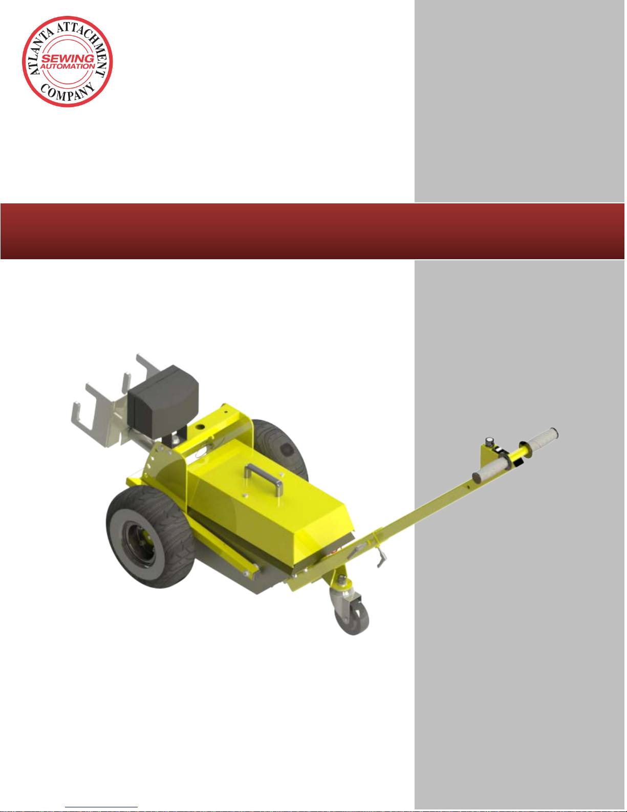
Technical Manual & Parts Lists
Model 701D
Atlanta Attachment Company
Revision 2 Updated Dec 14, 2015
362 Industrial Park Drive
Lawrenceville, GA 30046
770-963-7369 • www.atlatt.com
Page 2

IMPORTANT
It is important to read and understand the information contained within this
manual before attempting to operate the machine. Atlanta Attachment Co., Inc.
shall not be held liable for damage resulting from misuse of the information
presented within, and reserves the right to change the information contained
within, without prior notification.
ATLANTA ATTACHMENT COMPANY, INC.
Confidential and Proprietary Information
The materials contained herein are confidential and proprietary information of Atlanta
Attachment Company. In addition to any confidentiality and non-disclosure obligations that
currently exist between you and Atlanta Attachment Company, your use of these materials
serves as an acknowledgment of the confidential and proprietary nature of these materials
and your duty not to make any unauthorized use or disclosure of these materials.
All materials contained herein are additionally protected by United States Copyright
law and may not be used, disclosed, reproduced, distributed, published or sold without the
express written consent of Atlanta Attachment Company, which consent may be withheld in
Atlanta Attachment Company’s sole discretion. You may not alter or remove any copyright,
trademark or other notice from copies of these materials.
.
Atlanta Attachment Company
362 Industrial Park Drive
Lawrenceville, Georgia 30046
Teléfonos (770) 963-7369
Fax:(770) 963-7641
Email:[email protected]
Page 3

Technical Manual & Parts Lists
TABLE OF CONTENTS
SAFETY INSTRUCCIONS ................................................................................................................................. 3
1.- INSTALATION MANUAL`........................................................................................................................... 4
1.1.- PIECES AND COMPONENTS ......................................................................................................................... 4
2.2.- MOUNTING ................................................................................................................................................. 5
Handle Installation ....................................................................................................................................... 5
2.3.- SPECIFICATIONS ......................................................................................................................................... 5
Maximun Speed ............................................................................................................................................. 5
Batery Duration ........................................................................................................................................... 5
Weight ........................................................................................................................................................... 5
2.4.- DIMENSIONS ............................................................................................................................................... 6
2.5.- OPTIONS ..................................................................................................................................................... 6
2.- OPERATING MANUAL ................................................................................................................................ 7
2.1.- GENERAL DESCRIPTION .............................................................................................................................. 7
a.- Main Switch. ............................................................................................................................................ 7
b.- Control Lever ........................................................................................................................................... 7
c.- Direction Control (1) ............................................................................................................................... 7
d.- Speed Control (2) ..................................................................................................................................... 7
2.2.- OPERATION ................................................................................................................................................ 8
a.- Adjusting the Chassis Height ................................................................................................................... 8
b.- Operating the Unit ................................................................................................................................... 9
2.3.- REPLAC ING THE BATTERY ........................................................................................................................ 10
2.4.- CHARGING THE BATTERY ......................................................................................................................... 11
3.- SERVICE MANUAL .................................................................................................................................... 12
3.1.- TIRE SPECIFICATIONS ............................................................................................................................... 12
3.2.- PREVENTIVE MAINTENANCE .................................................................................................................... 12
Atlanta Attachment Company 362 Industrial Park Drive, Lawrenceville, GA 30046 E-mail: [email protected] Telephone: +1 (770) 9637369
2
Page 4

Technical Manual & Parts Lists
Safety Instructions
WARNING: All persons involved in operating and/or performing maintenance
to this equipment should read and follow the instructions of this manual. Use
this equipment only in the way this manual explains. The incorrect use can
cause damage to the equipment or persona l injuries. It is the responsibility of
the owner to be sure that the operator of this equipment read and unders tand
this manual before operate it. It is also the responsibility of the owner to be
sure that the operator is qualified and in good physical conditions, and also
has the adequate training in its operation.
General
The guidelines on security mentioned in this manual cover the entire line of products
manufactured by Atlanta Attachment Company. Some warnings and instructions my not
applied to this unit in particular. All maintenance should be performed by a qualified
technician
Security should be a constant concern for everybody. Always be very careful when working
with this equipment. Although all normal security precautions were taken in the design and
fabrication of this equipment, there are some potentially risk factors of security.
• W arning labels of s pecific security can be found on the equipment near to the immediate
areas of potential danger. These labels shouldn’t be eliminated or er ased. Replace them if
they turn unreadable.
• ALWAYS keep safety shields and covers in place, except for servicing.
• ALWAYS operate equipment in daylight or with adequate working lights.
• Follow daily and weekly checklists, making sure hoses are tightly secured and bolts
are tightened.
• ALWAYS watch and avoid holes or deep depressions.
• ALWAYS wear adequate eye protection when servicing the hydraulic system and
battery.
• NEVER operate a poorly maintained machine.
• NEVER allow persons to operate this machine without proper instruction.
• NEVER put hands or feet under any part of the machine while it is running.
• NEVER attempt to make any adjustments or repairs to the machine while running.
Repairs or maintenance should be performed by trained personnel only.
• NEVER work under the machine unless it is safely supported with stands, blocks or a
hoist and blocks.
• NEVER touch hot parts of machine.
• Do not operate the machine in areas where it can fall or overturn .
• Wet terrain can affect dramatically the traction.
Atlanta Attachment Company 362 Industrial Park Drive, Lawrenceville, GA 30046 E-mail: [email protected] Telephone: +1 (770) 9637369
3
Page 5
Technical Manual & Parts Lists
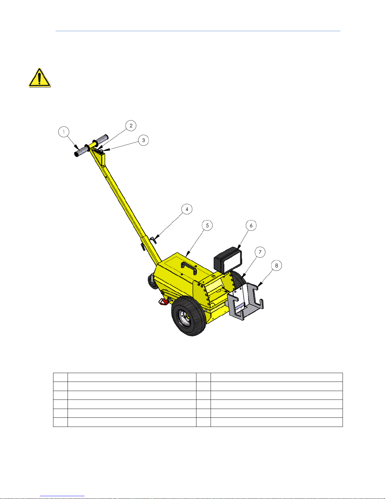
1
Handle
7
Tires
2
Forward/Reverse switch
8
Tighten the Cart Clamp
3
Speed Control
4
Adjust height of Handle
5
Batteries Chamber
6
Light
1.- INSTALATION MANUAL`
WARNING: It is important that the utility tug operator read this manual and is
familiar with all the functions and safety concerns of the unit before operating.
1.1.- Pieces and Components
Atlanta Attachment Company 362 Industrial Park Drive, Lawrenceville, GA 30046 E-mail: [email protected] Telephone: +1 (770) 9637369
4
Page 6
Technical Manual & Parts Lists
Effective Power
400W
Motor Voltage
24 V CC
Voltage Charger
1 ph 110/240V 50/60 Hz
Maximum Speed
3,7 mph / 6 kph
Battery Duration
3 hrs
Weight
110 Lbs / 50 Kgs
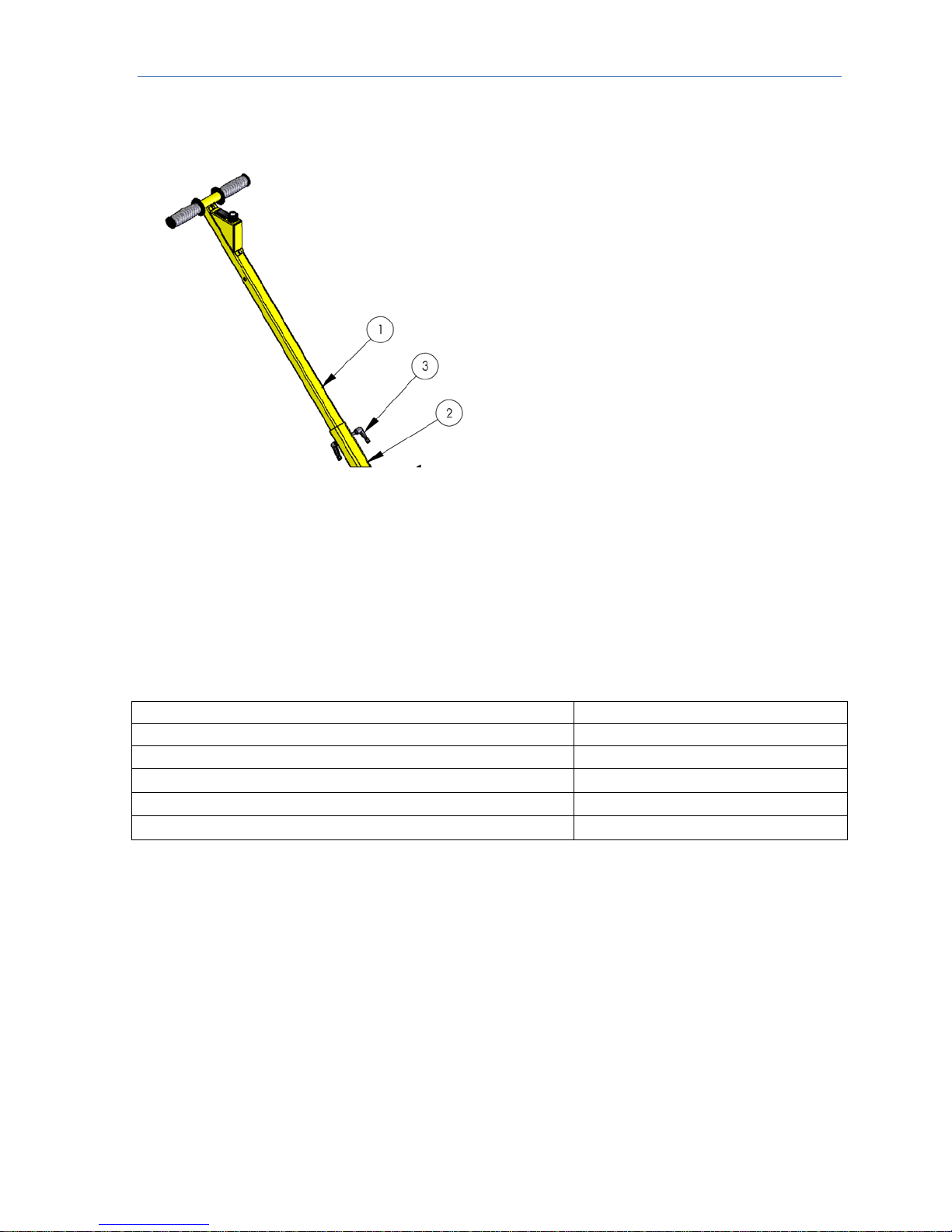
2.2.- Handle Bar Installation
1. Push the handle tube (1) inside the receiving tube (2).
2. Position the lever at the desired height and tighten the threaded shaft (3) to set its location.
2.3.- Specifications
Atlanta Attachment Company 362 Industrial Park Drive, Lawrenceville, GA 30046 E-mail: [email protected] Telephone: +1 (770) 9637369
5
Page 7
Technical Manual & Parts Lists
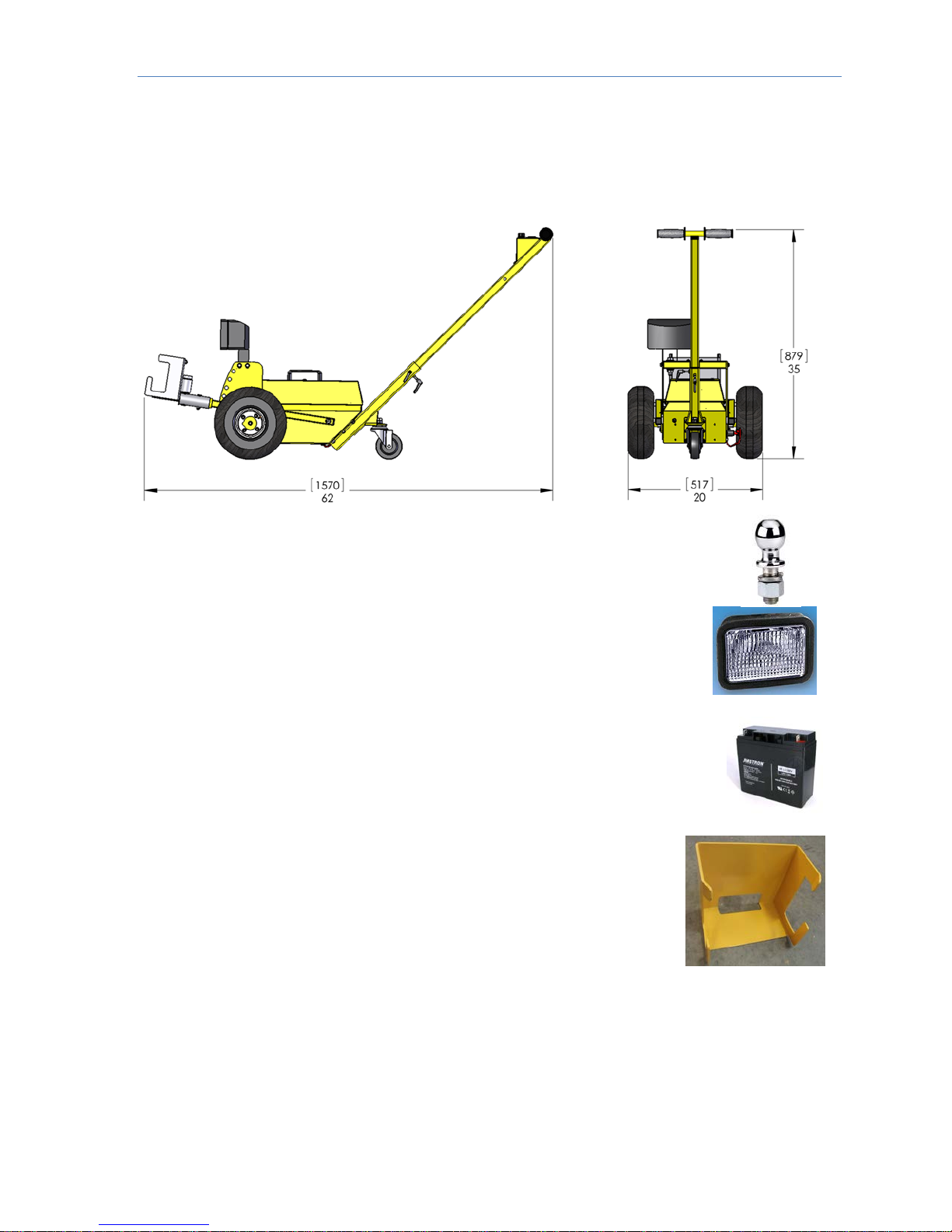
2.4.- Dimensions
Aprox. 62 "x 35" x 20 "(1570mm x 879mm x 517mm) depending on accessories
2.5.- Options
• Hitch ball attachment to facilitate move ment of boats and trailers.
• Light
• Adapters
• Batteries
• Clamps depending on hooks
Atlanta Attachment Company 362 Industrial Park Drive, Lawrenceville, GA 30046 E-mail: [email protected] Telephone: +1 (770) 9637369
6
Page 8
Technical Manual & Parts Lists
2.- OPERATING MANUAL
WARNING: It is important that the utility tug operator read this manual and is
familiar with all the functions and safety concerns of the unit before operating.
2.1.- General Description
This equipment is designed to move loads in flat surfaces to a maximum wei ght of
4.700 lbs. (2.000 Kgs.). There is not any other particular use implicit.
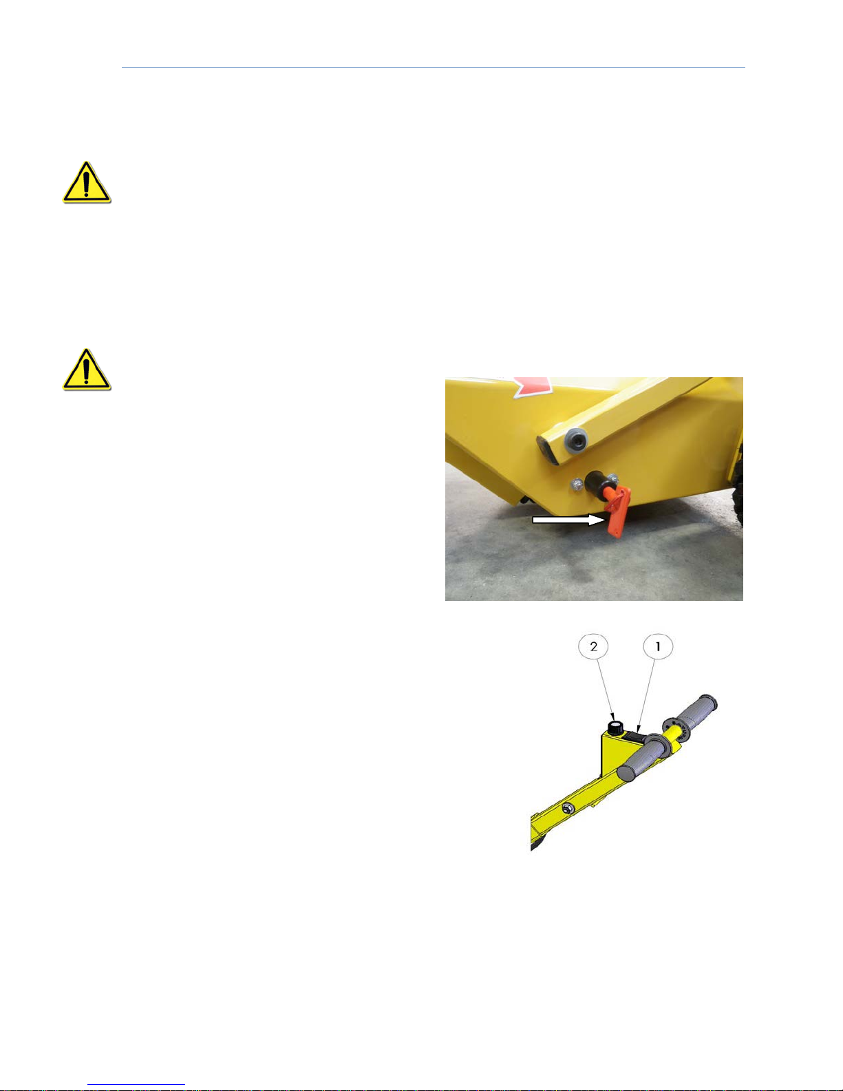
a.- Main Switch.
WARNING: The unit should remain de-energized when is not in use.
The main Switch is located in the bottom
right. It is responsible for cutting the
energy to the unit.
b.- Control Lever
The main operator control is located on
top of the control handlebar. It consists of the
following parts:
c.- Direction Control (1)
The utility tug moves forward or reverse by pressing
the corresponding side of the forward/reverse switch
(1). It has three positions: Forward / Reverse /
Center (Off).
d.- Speed Control (2)
Turn the speed control to the right to increase
speed. Turn the speed control in the opposite way to
reduce speed. The motor control has a “soft start”
and “soft stop”, function that allows it to maneuver
carefully.
Atlanta Attachment Company 362 Industrial Park Drive, Lawrenceville, GA 30046 E-mail: [email protected] Telephone: +1 (770) 9637369
7
Page 9
Technical Manual & Parts Lists
2.2.- Operation
WARNING: It is important that the utility tug opera tor r ead this manual and is
familiar with all the functions and safety concerns of the unit before operating.
.
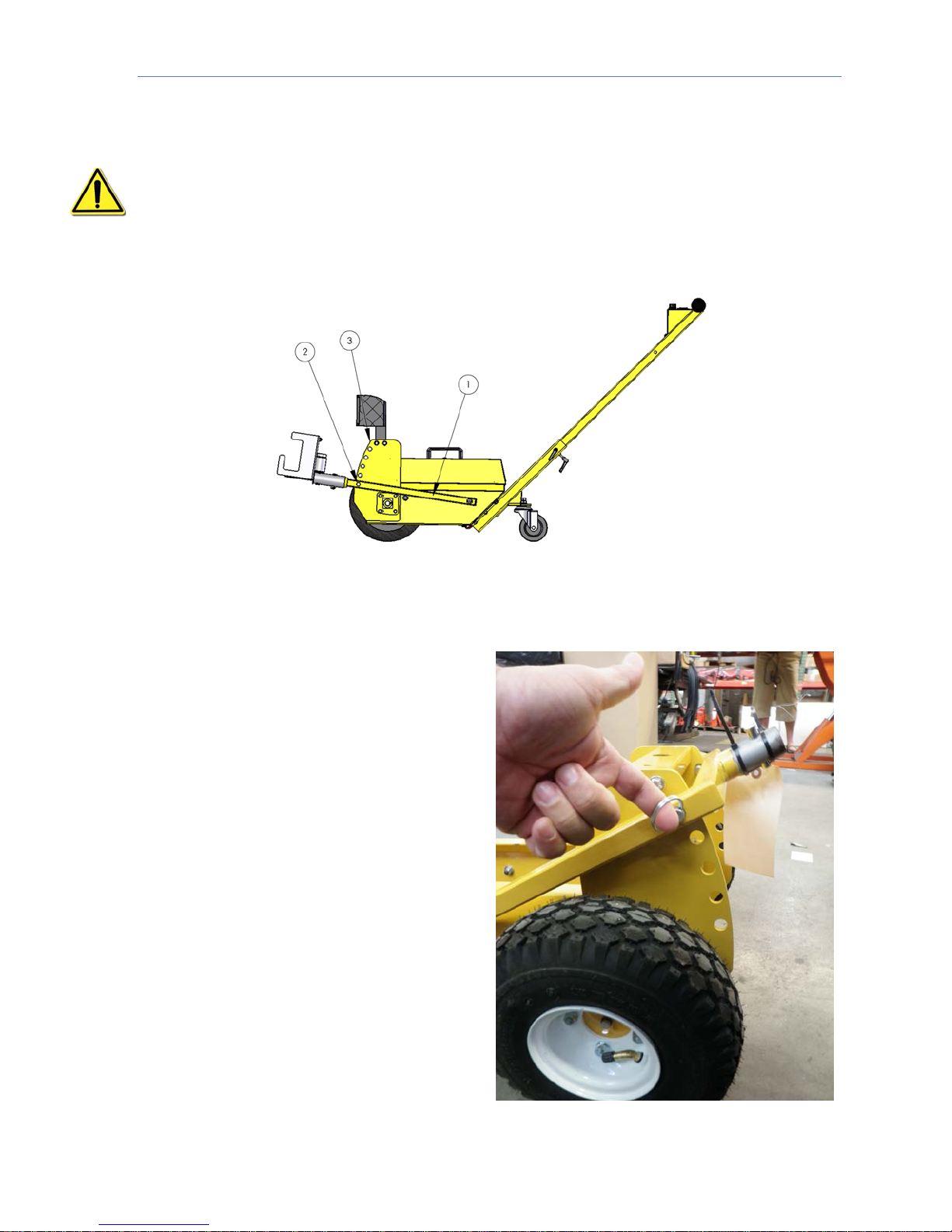
a.- Adjusting the Chassis Height
When the utility tug and the car to be towed are connected, it should be a minimum
of two inches (51mm) free space
between the ground and the rest of the
foot in the utility tug. This assures that
the utility tug will be able to pass over
any irregular surface and ensures the
traction of the equipme nt.
The adjustment is to change the angle of
the clamp (1).
1. Remove the clevis pins (2) of the side
plates.
2. Align the holes in the clamp with the
corresponding holes in the side plates
which provide the necessary angle to
reach the minimum space of 2”
Atlanta Attachment Company 362 Industrial Park Drive, Lawrenceville, GA 30046 E-mail: [email protected] Telephone: +1 (770) 9637369
8
Page 10
Technical Manual & Parts Lists
b.- Operating the Unit
WARNING: Before operating the uti lity tug, the operator should be completely
familiar with the proper use and functioning of the equi pment, it should read
the manual totally, and it should have practiced the slow manuevers to be very
familiar with the functioning of the equipment before try an operation at a
regular speed.
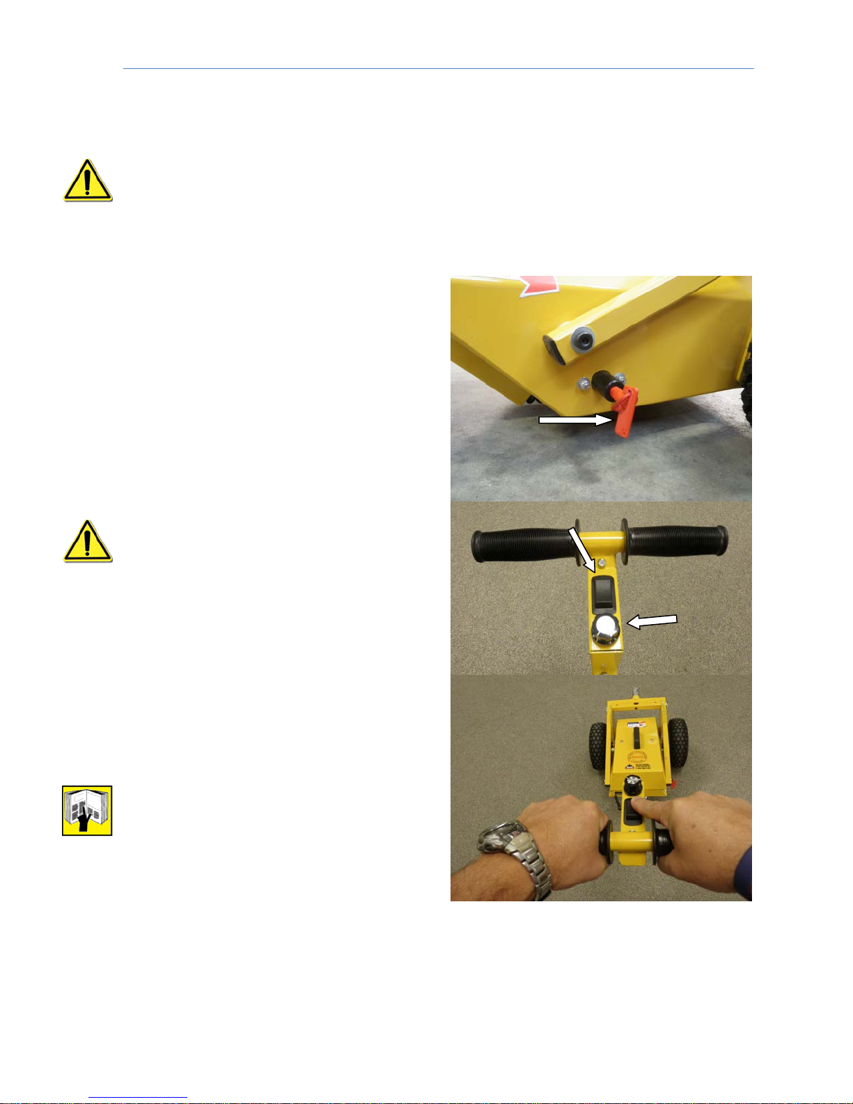
1. If it is necessary install a new battery
(see battery replacement)
2. Turn the switch On/Off to the On
position. The utility tug is active and ready
to function. Remember that when the
operation is completed return the switch
to the Off position.
3.- Turn the speed potentiometer de
counterclockwise to reach a slow speed.
WARNING: It is advisable to practice
all manuevers to become familiar with
the speed, controls and directional
methods before trying regular speed.
4.- Grab the handlebar firmly with both
hands. Active with one finger the
directional button and follow the force
exerted by the tug. Readjust the
potentiometer if it is necessary. Turn the
speed control to the right to increase
speed. Turn the control in the opposite
direction to reduce speed
Note: The Tug electronics will shut off
automatically in case of over or under
load.
5.- Turn the handlebar in the desire direction.
Atlanta Attachment Company 362 Industrial Park Drive, Lawrenceville, GA 30046 E-mail: [email protected] Telephone: +1 (770) 9637369
9
Page 11
Technical Manual & Parts Lists
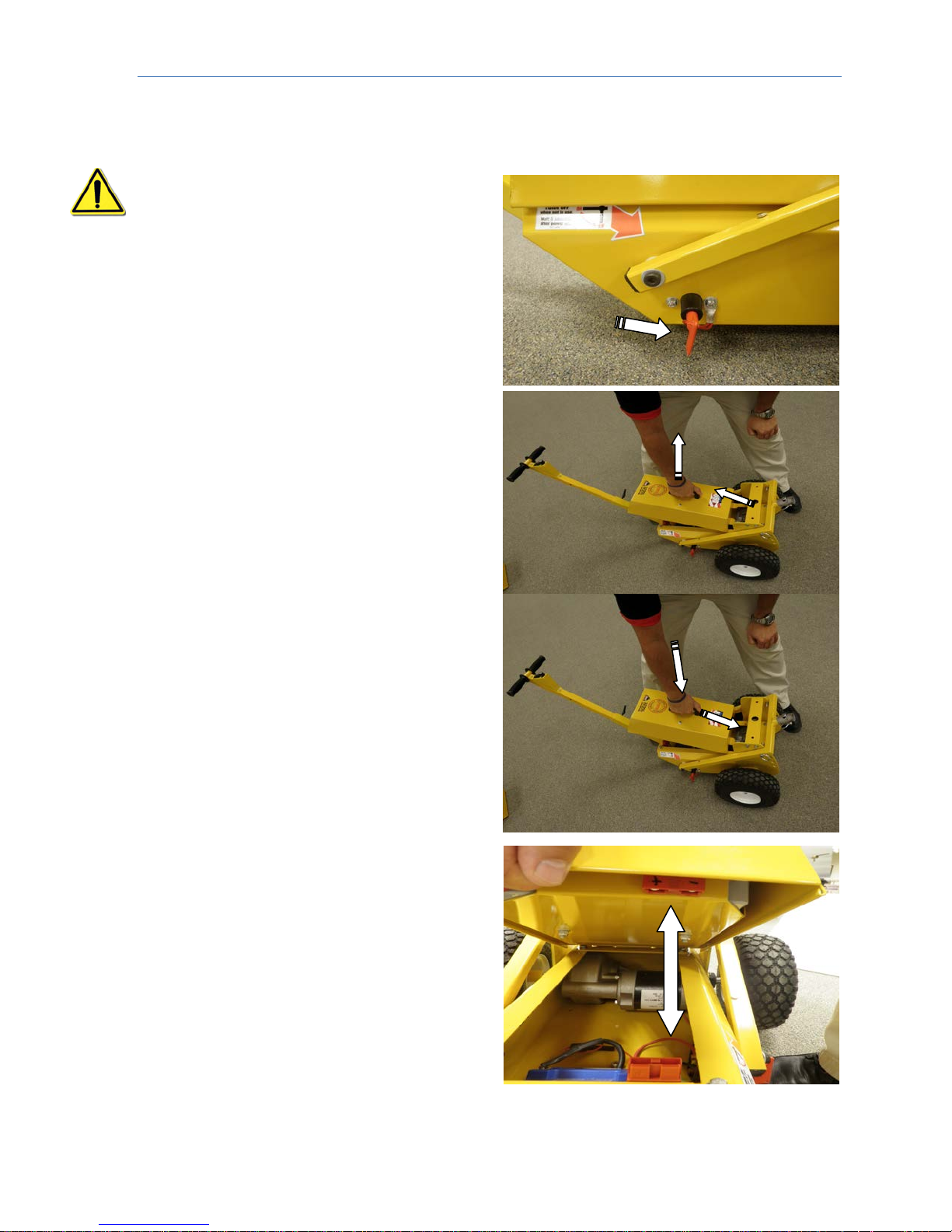
2.3.- Replacing the Batter y
WARNING: Always wear appropriate
protectors when handling batteries.
1.- Before taking out the battery from the
unit be sure that the switch On/Off is in
the Off position.
2.- Grab the battery from its handle, push
it up and remove it from its chamber..
3.- Do the opposite to place the battery
back.
4.- Be sure that the battery connector
snaps into the receptacle of the unit.
Atlanta Attachment Company 362 Industrial Park Drive, Lawrenceville, GA 30046 E-mail: [email protected] Telephone: +1 (770) 9637369
10
Page 12
Technical Manual & Parts Lists
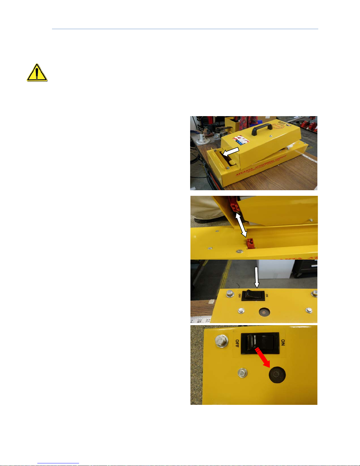
2.4.- Charging the Battery
WARNING: Always wear appropriate prot ect or s when handling batteries
Before connecting the battery to the charging unit, be sure that the switch On/Off is
in the Off position
1. Plug the cable from the load unit to an AC power source. (110 / 240 volts 50/60
Hz).
2. Take the battery by the carrying handle
and insert it into the charging receptacle;
ensure it is attached to the connector
receptacle
3.- Make sure the connectors are coupled.
4.- Change the position of the switch to
On.
5.- The charger unit will determine
automatically the batteries status and it
will charge them accordingly with their
status. A FLICKERING light in the charger
(Red Arrow) will indicate that the batteries
are fully charge. A STEADY light in the
charger indicates that charge is in
progress. Once the charge is finished,
turn the switch off and remov e the battery.
Atlanta Attachment Company 362 Industrial Park Drive, Lawrenceville, GA 30046 E-mail: [email protected] Telephone: +1 (770) 9637369
11
Page 13
Technical Manual & Parts Lists
3.- SERVICE MANUAL
WARNING: It is important that the utility tug operator re ad this manual and is
familiar with all the functions and safety concerns of the unit before operating.
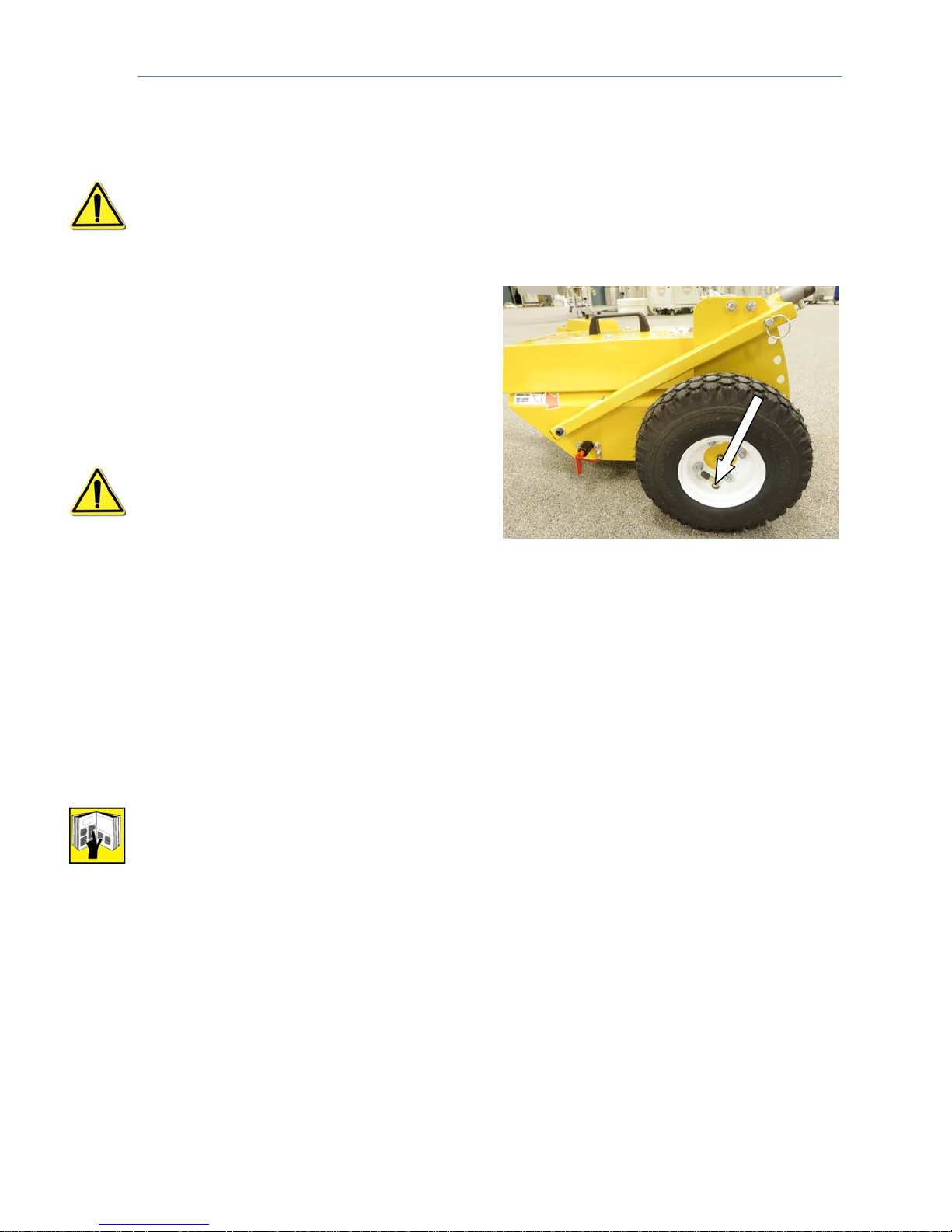
3.1.- Tire Specifications
It is important that the tires are inflated
and that both have a pressure of 25 psi.
(1.7 bar) For heavy load operations
reduce the pressure of the tires a 20 psi.
(1.4 bar) These lower pressures allow a
better grip and prevent with heavy loads
the tires from sliding.
WARNING: Use extreme precaution
when inflating the tires. Avoid over
inflation because there is a danger of
explosion.
3.2.- Preventive Maintenance
Regular maintenance is the best prevention to avoid costly downtime and early
repair jobs
a.- Daily
1.- Keep the unit clean; remove deposits of dirt and debris that can cause
malfunctions etc.
2.- Clean grease deposits, oil and debris, especially in the battery area.
3.- Make sure there are not threads or strings of rope entangled in the tires.
NOTE: This unit does not require practically of a preventive maintenance but
the following recommendations are important:
a.- Be aware of noises that could potentially indicate a problem.
b.- Inspect visually the unit for any abnormal ware or damages.
c.- A good moment to detect potential problems is with a programmed maintenance.
To fix the problems as quick as possible is the best insurance.
Atlanta Attachment Company 362 Industrial Park Drive, Lawrenceville, GA 30046 E-mail: [email protected] Telephone: +1 (770) 9637369
12
Page 14
Technical Manual & Parts Lists
Atlanta Attachment Company 362 Industrial Park Drive, Lawrenceville, GA 30046 E-mail: [email protected] Telephone: +1 (770) 9637369
13
Page 15
Technical Manual & Parts Lists
Atlanta Attachment Company 362 Industrial Park Drive, Lawrenceville, GA 30046 E-mail: [email protected] Telephone: +1 (770) 9637369
14
Page 16

Technical Manual & Parts Lists
Atlanta Attachment Company 362 Industrial Park Drive, Lawrenceville, GA 30046 E-mail: [email protected] Telephone: +1 (770) 9637369
15
 Loading...