


MPT
40Amp Charge Controller
Display Kit
Part#PVCM40D-MPT & SEDM6-40
SUNEXPLORER II-MPT™
Manufactured by: Atkinson Electronics, Inc.

Table of Contents
Diagrams ........................................................................................ 1
Description ..................................................................................... 2
Kit Contents .................................................................................... 3
PVCM40D-MPT Description of Operation ................................... 3
SEDM6-40 Description of Operation ........................................... 4
New Installation Instructions for PVCM40D-MPT ..................... 5
Installation Instructions for PVCM40D-MPT .............................. 5
Installation Tips for PVCM40D-MPT ............................................ 6
Battery Type Selection .................................................................. 7
Power Up Initialization Routine ................................................... 8
Battery Type Selection Switch ...................................................... 8
Charging Mode Definitions ........................................................... 9
Charge Type LED Definitions ........................................................ 9
Battery Status LED Definitions ..................................................... 9
Charging Stage Descriptions ...................................................... 10
Charging Stage Descriptions Continued ................................... 11
Wiring Diagram .......................................................................... 12
Installation Instructions for SEDM6-40.................................... 13
Battery Adjustment Pot & Jack Locations ................................ 14
Installation Tips for SEDM6-40 ................................................. 14
User Instructions for SEDM6-40 ............................................... 15
Trouble Shooting Tips for PVCM40D-MPT .............................. 16
Specifications for PVCM40D-MPT ............................................. 17
Specifications for SEDM6-40 ..................................................... 18
Wire Size Recommendation Chart ............................................ 19
Cleaning Tips & Template for SEDM6-40 ................................. 20
Appendix-A .................................................................................. 21
Warnings & Recommendations ................................................. 22
Limited Warranty ....................................................................... 23
www.atkinsonelectronics.com Circuit Board Division
800.261.3602 Revised 05/19

Features
PVCM40D
SEDM6-40
www.atkinsonelectronics.com Circuit Board Division
800.261.3602 Revised 05/19
1

Description
PVCM40D-MPT
Mounting Holes: Accepts a #8 sheet metal or wood screws.
¼” Brass Bolt: Connects to the + battery terminal wire.
¼” Brass Bolt: Connects to the + solar (PV) panel wire.
¼” Push on Spade Connector: Connects to the – battery terminal or wire.
Battery Type Dip Switch: Select your battery type.
RJ-45 Jack: Power and signal connection point for the SEDM6-40 display module.
(Requires Cat-5 patch cable).
Charge & Battery Status LED’s: Charge mode LED indicates the charging stage. The
charge type LED indicates the type of charge: soft, bulk, absorption, float, equalization
boost. The Battery status LED indicates the level of charge: 6 levels from full to empty.
SEDM6-40
Display Processor: Microprocessor controls all display and read-out functions.
Battery Voltage Adjust P1: Displays battery voltage adjustment potentiometer. Set
during step 2 of SEDM6-40 installation.
Solar Voltage Adjust P2: Displays solar voltage adjustment potentiometer. Set during
step 3 of SEDM6-40 installation
RJ-45 Jack: Power and signal connection point to PVCM40D-MPT charge controller
module. Requires Cat-5 patch cable.
Cable Error LED: Lights when a crossover cable is connected.
3 Digit Backlit LCD Display: Lights for 15 seconds every time the select button is
pressed
Mode Select Button: Allows user to change display read out, reset solar Amp hour
accumulator, and lock display setting.
Selection Indicators: Indicates which of 6 readings is displayed.
www.atkinsonelectronics.com Circuit Board Division
800.261.3602 Revised 05/19
2

Kit Contents
SEDM6-40 PVCM40D-MPT
PVCM40D-MPT Description of Operation
The PVCM40D-MPT, micro-processor based, solar 5 stage charge controller connects PV
panels to 12VDC storage batteries. PVCM40D-MPT performs 5 basic functions:
1. Monitors solar panels to know if it has enough solar voltage to start charging the
battery(s), and when to adjust the PWM charge rates based on solar conditions.
2. Monitors the battery voltage to know when the battery(s) have completed the bulk
and absorption charging stages and has entered the float stage.
3. It adjusts the PWM charge algorithms based on the varying load and solar conditions
to maintain maximum charging current throughout the charging process.
4. It checks the available solar charge voltage every second to make sure there is
sufficient charge voltage. If not, it suspends the charging routine until the solar voltage
increases or drops below 5VDC at which point it enters night or End of Day routine
(EOD).
5. It compensates for battery temperature and adjusts the charge thresholds voltages
when mounted in the battery area.
www.atkinsonelectronics.com Circuit Board Division
800.261.3602 Revised 05/19
3

SEDM6-40 Description of Operation
The SEDM6-40 display module serves as a remote digital readout for either the PVCM40D-MPT or
PVCM40D-SE2 charge controller. The SEDM4-25 display module serves as a remote digital readout for
the PVCM25D charge controller. The display units and controllers are not interchangeable. The
PVCM40D-MPT charge controller contains an internal solar current shunt, RJ-45 network jack and
associated internal wiring to provide power and signals to the SEDM display unit through a standard
computer network patch cable which plugs into the RJ-45 jack on the back of the SEDM.
If the wrong configuration network cable, such as the crossover type, is used then the error LED on the
back of the SEDM6-40 will light indicating that the wrong type cable has been plugged in for the display.
The SEDM6-40’s normal display indication is Battery Percent Remaining and its associated LED. The
select button allows the user to turn on the displays backlight, advance to the next display setting, reset
the solar Amp hour accumulator, force the PVCM40D-MPT into a bulk charge routine to top off the
battery voltage, lock display or current setting, or activate scroll mode (see page 15). The SEDM6-40 will
automatically switch back to the battery percent remaining display setting after 4 minutes unless the
display setting lock is activated. The backlight will come on for 15 seconds any time the select button is
pushed and will stay on continuously in scroll mode.
If a low battery voltage condition occurs, the display will automatically switch to the battery voltage
setting and blink the display reading and battery voltage LED. If the user accesses other display settings
while in this condition, they will be displayed for 5 seconds then switch back to battery voltage setting
until the low battery voltage problem is corrected. Any accumulated values may be meaningless if the
battery voltage remains below 10V as the minimum voltage for the SEDM6-40 to operate properly is
10VDC. The SEDM6-40 display will continue to accumulate Amp-hours, they won’t be displayed without
reverting back to the flashing battery voltage after 5 seconds.
If the charging Status LED is green, the user can scroll down to the charging status position. The user can
tell the charge controller to top-off the battery(s), provided there is sufficient PV voltage to do so. This is
done by pressing the select button and holding it, this will cause the display to blink the ‘n_c’ 3 to 4 times
telling the controller to go into charge mode. The LED color changes to red and the display indicates
‘chr’, then release the select button The display will then alternate between solar charge Amps and
battery voltage, switching every 10 seconds, (backlight will be on during the charging cycle), until the
charge cycle is complete, in which the display then returns to battery percent remaining.. You can exit
display cycle by pressing the Select button.
www.atkinsonelectronics.com Circuit Board Division
800.261.3602 Revised 05/19
4

New Installation Instructions for PVCM40D-MPT
1. Complete the installation of the solar panels following the solar panel manufacturer’s instructions for
panel mounting and wire size based on total wattage of the solar panels and the distance between
panels and batteries. If the distance is less than 15 feet and the total solar panel charge Amps is 40
Amps or less, 8 AWG wire or larger is recommended. If the distance is greater than 15 feet use a 6
AWG wire. Reference the wire size recommendation chart.
2. Complete the installation of the optional display module and cat5e cable run to the charge
controller’s mounting location.
3. Identify the polarity (positive and negative) on the wires used for the battery and solar panels. Wire
the PVCM according to the wiring diagram (page 12). Keep the solar panels covered with an opaque
material until wiring and setup is complete.
4. Choose a location for the controller that is close to the battery location to minimize the voltage drop
when charging. The recommended location should be away from moisture and heat sources and
protected from weather.
5. Mount the PVCM controller in or next to the battery box for temperature compensation routines to
work properly using two ½ inch # 10 wood or sheet metal screws. Remove the fuse from the fuse
holder.
6. The red and black wires used to connect to the battery should wire directly to the controller using
proper ring terminal connectors.
7. Connect the positive wire from the solar panels to the PV connection on the controller, and connect
the panel’s negative wire to the battery negative terminal. Set the Battery type DIP switch for your
battery type. See diagram showing the switches and the four battery type settings.
8. Review all your wire connections to avoid any reverse polarity connections before re-installing the
fuse.
5
www.atkinsonelectronics.com Circuit Board Division
800.261.3602 Revised 05/19

Installation Instructions for PVCM40D-MPT
Battery Type Flooded Lifeline AGM. Sealed/Gel
Absorption voltage: 14.4 VDC 14.3 VDC 14.3 VDC 14.1 VDC
Float voltage: 13.7 VDC 13.4 VDC 13.5 VDC 13.3 VDC
Equalization voltage: 15.0VDC N/A N/A N/A
Conditioning voltage: N/A 15.5 VDC ** N/A N/A
**LIFELINE® Battery’s Technical Manual Rev. E Section 5.5 Conditioning, outlines the conditions
that should have occurred before the battery(s) are to be conditioned, the conditioning
recommendations as to the procedure, and how long and how often. Requires a minimum of 10+
Amps of total solar charging current.
Installation Instructions for PVCM40D-MPT
1. Exposed connections should be waterproofed. Grease or silicon will adequately protect connections
such as splices or the network cable jack. Moisture causes un-protected connections to oxidize,
making them highly resistive which will cause the controller to not work properly.
2. When wiring the PV panel into the battery system, adequate wire size must be used. An 8 AWG wire
for short distances and a 6 AWG or larger wire for longer distances is recommended. If a smaller wire
is used, the wire’s resistance is higher which produces a higher voltage drop between battery(s) and
solar panels and the battery(s) will not achieve full charge.
See WIRE SIZE RECOMMDATION CHART for size verse distance. (Page 19)
3. When first powering your PVCM40D-MPT controller, make user you have selected to correct dip
switch settings for your battery type. If you have flooded lead acid batteries, check the battery fluid
level as directed by the battery manufacturer.
4. Install the PVCM40D-MPT in or next to the battery enclosure for the temperature compensation to
work properly.
5. Recommended for Lifeline batteries, a minimum of 3- 90 watt 12V panels with Imp = 5.0 Amps or
greater or 2- 160 Watt 12V panels with Imp = 8.8 Amps.
Recommended dielectric grease for ALL power connections
between solar panels, PVCM40D-MPT charge controller and
battery bank.
Brand : Ideal Noalox or Permatex
Google it!
www.atkinsonelectronics.com Circuit Board Division
800.261.3602 Revised 05/19
6

Battery Type Selection Switch
Flooded Lead Acid (wet) battery(s): Set both DIP switches (1 & 2) to the open position, then
power the controller by connecting the black ground wire to the ground spade connector.
Battery equalization automatically occurs when the battery voltage drops below 12.1VD C for
the 3rd time in a 14 day period or once in a 28 day period. The controller blinks the charge
type LED blue when the equalization flag has been set, and when conditions are met it then
will run the equalization routine, turning the charge type LED on solid blue, to bring the
internal cells of the battery to an equal state to reverse the effects of being discharged below
12.1VDC.
Lifeline ® AGM battery: Set both DIP switches (1 & 2) to the closed position, then power the
controller by connecting the black ground wire to the ground spade. Lifeline recommends
using a minimum of a 3 stage charger to fully charge their batteries. The Lifeline setting uses a
specific algorithm that follows Lifeline’s charging recommendations. The Lifeline AGM
batteries can be conditioned* (equalized) when the battery is showing symptoms of capacity
loss due to extended time in a partial or low state of charge as a result of limited charging
current. The PVCM40D-MPT’s Lifeline algorithm monitors the battery condition and will
perform a conditioning charge, provided the following requirements and conditions are met:
MINIMUM Imp of 12 Amps (2x-100 to 160 Watt solar panel), and must complete a full charge
cycle. Conditions to set conditioning flag which will cause the charge type LED to blink Blue
are: Battery voltage drops below 12.1VDC or the controller fails to complete its charge cycle 3
times in a 14-21 day period. Conditioning will only once in a 21-28 day period. If solar panels
don’t produce 10+Amps of charging current during bulk charge, the conditioning routine is
not activated, during that days charging routine. It will retry the following days charge
routine.
Other Brands of AGM batteries: Set DIP switch 1 to the closed position and switch 2 to the
open position, then power the controller by connecting the black ground wire to the ground
spade. This AGM algorithm is configured for most types of AGM batteries, requiring a
minimum of 3 stage PWM charger with slightly lower charging voltage thresholds than those
of Lifeline batteries. This setting does NOT perform any battery conditioning.
Sealed/gel batteries: Set DIP switch 1 to the open position and switch 2 to the closed
position, then power the controller by connecting the black ground wire to the ground spade.
The sealed/gel battery algorithm is configure for the average sealed/gel rechargeable battery,
recommending a 3 stage PWM charger with charging voltage thresholds. It does NOT perform
a battery conditioning.
7
www.atkinsonelectronics.com Circuit Board Division
800.261.3602 Revised 05/19

Power Up Initialization Routine
To power up the controller, insert the fuse into the battery wire fuse holder or switch on the circuit
breaker. The controller cycles each LED thru its three colors:
Charge monde & battery status Red, orange & green
Charge type Red, blue & magenta
The controller then checks its voltage inputs, the battery type DIP switches and looks for any flags. The
controller then enters ready mode, re-reading the battery & solar panel voltages, if the solar voltage is
less than 10VDC, it displays the battery status level by blinking the status LED once every 10 seconds:
Green Full
Orange Partial
Red Low
If the solar voltage is greater than 10VDC it turns on the LED to indicate battery level. If the battery
voltage is less than 10.5VDC it blinks the battery status LED red and sets a soft charge flag, blinking the
charge type LED red, and sets the battery equalization flag alternating between red and blue. The
controller then determines if there is enough solar voltage to charge, if the voltage is less than the
minimum voltage for charging, the charge mode LED remains off. Once the solar voltage reaches the
minimum operational voltage it again checks the battery voltage to determine the absorption time, and
checks for a soft charge flag. If the soft charge flag is set, then it enters the charge routine turning on the
charge mode and type LEDs red to indicate it is in a soft/ bulk charge. If the soft charge flag was not set,
then the charge mode LED will be lit red indicating it is in
Battery Type Selection Switch
The PVCM40D-MPT’s battery type selection dip
switch is located left of the cat5e jack for the
SEDM6-40 display module.
The PVCM40D-MPT has three bi-color LED’s,
one each for the three following conditions:
Charging mode: Red, orange, green
Charge type: Red, magenta, blue
Battery level status: Red, orange, green
8
www.atkinsonelectronics.com Circuit Board Division
800.261.3602 Revised 05/19

Charging Mode LED Definitions
The Charge Mode LED indicates which of the three main PWM charge stages the controller is in:
Bulk charge stage - The LED is lit red
Absorption charge stage - The LED blinks red
Float charge stage - The LED is lit green
If the charge mode LED is not lit, it means that there is not enough sun light to charge the battery,
controller is in night mode.
Charge Type LED Definitions
The charge type LED indicates the types of charge the controller is in:
Soft Charge - The LED is lit red.
Soft charge is set when the battery voltage drops below 11.0VDC.
Once battery voltage climes above 11.5VDC it turns off.
Equalization Conditioning - The LED blinks blue.
Equalization flag is set when the battery voltage drops below 12.1VDC three times in a 14 day
period.
It is continuously lit while in equalization mode.
Auto Boost - The LED blinks magenta when the auto boost flag is set.
It is continuously lit during the bulk and absorption phase of the boost cycle. It turns off once the
controller returns to float stage.
The charge type LED is not normally lit, if any of the above conditions occurs, it will then blink or light
continuously, indicating the charge it’s in.
While in the float charge stage, if the load currents exceeds the solar charge current and the controller
can’t maintain the float voltage, the charge mode LED will blink green. If the battery voltage drops below
13VDC for 5 minutes the controller sets its auto boost flag and blinks the charge type LED magenta. Once
the load is reduced or the solar charge current increases and battery voltage returns to float voltage, the
charge type LED turns on, until it completes the auto boost charge cycle.
Battery Status LED Definitions
The battery status LED indicates six levels of charge: full, high, medium, partial, low and empty.
COLOR POWER BATTERY SOC VDC
Lit Green Full 100% >12.8
Blinking Green High 95 to 70% 12.8 down to 12.4
Lit Orange Medium 70 to 50% 12.4 down to 12.1
Blinking Orange Partial 50 to 30% 12.1 down to 11.8
Lit Red Low 30 to 10% 11.8 down to 11.5
Blinking Red Empty 0% <11.5
9
www.atkinsonelectronics.com Circuit Board Division
800.261.3602 Revised 05/19

Charging Stage Descriptions
Stage 1 - Soft Charge
When the batteries are discharged below 10.5VDC, the controller will softly ramp up the charge rate until the
battery voltage reaches 10.5VDC at which point it will enter the bulk charge stage. (Battery status LED blinks
red, charge type & charge mode LEDs will be lit red).
Stage 2 - Bulk Charge
Maximum charge current from solar panels is applied to the battery(s) until it reaches the absorption voltage
threshold for your battery type selected on DIP switches 1&2. (Charge mode LED will be solid red).
Stage 3 - Absorption Charge
The battery voltage is maintained at a constant voltage using PWM technology to finish charging the
battery(s) to 100% of charge.
The controller uses Multi Point Tracking (MPT) to compensate for changing loads and solar conditions to
maintain constant charge rate. (Charge mode LED will blink red).
Stage 4 - Battery Equalization Charge
Battery equalization is only available for (wet) flooded lead acid battery(s). Battery equalization automatically
occurs when the battery voltage has dropped below 12.1VDC for the third time within a 14 day period or
once in a 28 day period. The controller blinks the charge type LED blue when the equalization flag is set, and
will run the equalization routine once the conditions are met, to bring the internal cells of the battery to an
equal state to reverse the loss of capacity due to being discharged below 12.1VDC.
Red: Charge mode
Blink Red: Absorption charge
Blue: Equalization charge
10
www.atkinsonelectronics.com Circuit Board Division
800.261.3602 Revised 05/19

Charging Stage Descriptions Continued
Stage 4a – Lifeline Conditioning Charge
Lifeline batteries can be conditioned if the total Imp. from the solar panels is greater than 10 Amps.
The PVCM40D-MPT monitors the solar charge Amps during the Bulk charge stage, if 10+ Amps was
detected it sets the 10 Amp Flag. The controller also monitors the battery voltage over a 14 to 21 day
period, if the battery voltage drops below 12.1VDC three times in that period or fails to finish the
Absorption charge before end of day during that period it sets the conditioning flag. At the end of the 21
day period the controller must see
10+Amps of charge current during the Bulk charge and complete the full charge cycle before it begins a
conditioning cycle. If the panels don’t produce 10+Amps during the bulk charge the conditioning charge
is not activated that day and will try again during the next day’s charging cycle. Conditioning will only
occur once in a 21 - 28 day period.
Stage 5 - Float Charge
The batteries are fully charged at this point and are maintained at a safe voltage level. During the float
charge the controller is constantly adjusting its PWM control to adjust for varying solar charging
currents and trailer loads to maintain a float voltage of 13.5VDC for sealed/gel batteries and 13.7VDC for
lead acid & & AGM batteries.
Green: Charge mode.
Stage 6 – Auto Boost Charge
The auto boost feature is as follows: The controller is in float charge, the trailer loads become greater
than the solar charging current and the battery voltage is pulled below 13.0VDC for more than 5
minutes. The auto boost flag is set, when the loads are reduced to the point where the float charge
returns the battery voltage back to float voltage, the controller then performs a shortened
Bulk/Absorptions charge cycle restoring the battery(s) to 100% and then returns to the float charge.
Charge type LED will blink magenta when auto boost flag is set and will on continuously during the
charge cycle.
Stage 6a – Manual Boost Charge
The PVCM40D-MPT & SEDM6-40 provides the user, the ability to perform a manual boost charge, any
time the controller is in the float charge stage when a SEDM6-40 display is used with the MPT controller.
The Manual boost feature is not available when using either PVCM4 or SEDM4 displays. To perform a
manual boost charge, the charge controller must be in the float stage as indicated on the controller or
the display’s charge status LED is green. The operator uses the SEDM6-40 display’s select button to
scroll down to the charge status location, then presses and holds the select button until the green LED
turns Red. The PWM controller’s charge mode LED changes from green to red and the charge type LED
will light magenta in color. When the controller finishes the manual boost charge it returns to the float
Stage and the displays charge status LED will turn green.
11
www.atkinsonelectronics.com Circuit Board Division
800.261.3602 Revised 05/19

Wiring Diagram
www.atkinsonelectronics.com Circuit Board Division
800.261.3602 Revised 05/19
12

Installation Instructions for SEDM6-40
1. Complete the installation and test the operation of the PVCM40D-MPT charge control module.
2. Before mounting the SEDM6-40 module, plug in a short cat5e network cable into both, the
PVCM40D-MPT controller’s RJ-45 jack and the SEDM6-40 display’s RJ-45 jack and verify that all
readings work properly.
3. Next measure your battery voltage at the battery with a volt meter, then calibrate the display’s
battery voltage reading by selecting the battery voltage setting on the display and then adjusting the
P2 potentiometer on the back of the display +/- 1/4 turn on the adjustment pot so it reads correctly.
4. Next remove the fuse from the controller’s PV in-line fuse holder and measure the voltage on the PV
side of the fuse clip and ground. Re-insert the fuse and scroll down to the solar panel voltage reading
on the display and adjust P4 potentiometric on the back of the display +/- 1/4 turn on the
adjustment pot so it reads correctly.
5. Determine the mounting method to be used, surface-cutout or single electrical box ring.
6. For surface-cutout mounting, place the template (found on page 20 of this manual) over the desired
mounting location and mark through the template the two mounting screw locations. Drill two pilot
holes into the cabinet or mounting surface at the marked locations. Use a Phillips screw driver to
drive the screws into the mounting surface before mounting the display module. Back out the screws,
cut-out the template leaving the mounting screw areas and attach the template with the screws to
the mounting surface. Draw around the template on the mounting surface marking through the
template around the mounting screw tabs. Carefully cut out the marked area using a hole saw or
rotary tool leaving the mounting screw areas.
7. For single gang electrical box ring mounting, use the ring as a templet and mark the area to be cut
out. Carefully cut area for the mounting ring, mount the box securely and install optional conduit if
desired.
8. Unplug the short network cable from both the controller and display. Next route or pull the display
end of the network cable into the mounting area or electrical box, being careful not to damage the RJ45 plug.
9. Plug the network cable into the controller’s RJ-45 jack, then after pulling it through the cutout hole,
plug it into the display’s RJ45 jack, the SEDM will power up turning on its backlight, and use the
select button to scroll thru and to verify the readings. Push any excess CAT-5 wire back into the hole
and mount the display. Insert the screws through the front of the SEDM6-40 module and into the
holes and tighten by hand with a Philips screwdriver to avoid damaging the SEDM6-40 display.
10. Use grease or silicone to cover the controller’s end of the Cat5e network cable plug to avoid
corrosion.
www.atkinsonelectronics.com Circuit Board Division
800.261.3602 Revised 05/19
13

Battery Adjust Pot & Jack Locations
Installation Tips for SEDM6-40
1. When a network cable (up to 50 feet long), is used to connect the SEDM6-40 to the PVDCM25D-
MPT charge controller, it must be the straight through type or the display will not read properly. A
cable error LED will light up brightly on the back of the meter if the wrong type of cable such as the
crossover type is used.
2. The minimum solar charge current the SEDM6-40 will indicate is about 0.30 Amps. Below this
value the SEDM6-40 will display “chr” if the PVCM40D-MPT is passing solar charge current to the
battery. The current display reading will indicate “0" if the controller is not in any of the charging
stages.
3. The solar current shunt used in the PVCM40D-MPT is rated for a maximum of 25 Amps. There are
other displays and charge controllers in the SUNEXPLORER product line for higher Amperage
systems.
The SEDM6-40 display module serves as a remote digital readout for the
PVCM40D-MPT charge controller. The display units and controllers ARE NOT
interchangeable with other parts from other kits.
www.atkinsonelectronics.com Circuit Board Division
800.261.3602 Revised 05/19
14

User Instructions for SEDM6-40
1. The power and signals to the SEDM6-40 display are supplied through the cat5e network cable
connecting the SEDM6-40 to a PVCM40D-MPT charge controller.
2. The SEDM6-40 will normally revert back to displaying the continuous battery percent remaining after
approximately 4 minutes from any other reading.
3. Select button operation:
Tapping or pressing the select button activates the backlight for 15 seconds. Pressing the select
button to advance, resets the 15 second timer.
Pressing for 1 second then releasing the button advances to the next reading.
From the battery voltage display only, pressing and holding the button will advance the display
automatically through each of the readings.
1. If the button is released before returning to the battery voltage display, the reading will remain
in that position until the display times out (4 min).
2. If the button is held through all readings then released after the battery voltage display, the
SEDM6-40 will enter the scroll mode, advancing to the next reading every 3 seconds,
indefinitely.
3. Tapping the button exits the scroll mode.
4. A low battery voltage condition will also exit the scroll mode.
Display lock mode is available for solar charge Amps and battery %.
1. To lock display from timing out and reverting to battery % remaining, advance display to
desired position then press and hold the button until the display flashes (approximately 3
seconds).
2. Release button when the display stops flashing, it will remain indefinitely in that reading.
3. Tapping button while the display is flashing prevents entering lock mode.
4. Advancing to the next reading cancels the lock mode.
5. Low battery voltage also cancels the lock mode.
Resetting the solar accumulated Amp hour reading to zero.
1. Pressing and holding the button for approximately 6 seconds will reset the display value. The
display starts flashing after 3 seconds, the reading goes to zero after 6 seconds and the display
stops flashing.
2. Releasing the button while the display is flashing cancels the reset. The display will stop flashing
and retain its current value after several sec.
Battery voltage top off-advance to charging status, display will indicate “Fch”.
1. Press and hold the select button the display will flash “Fch”once, telling the charge controller to
enter the charge routine. When controller enters charge mode the displays green status LED
turns RED and the display indicates ‘chr’, 3 second later display jumps to solar charge Amps and
shows the charging current for 10 seconds, then to battery voltage showing the battery voltage,
then it alternates between them until it exit the charge routing or the select button is pressed.
Low battery voltage will cancel any user selections. The user can advance to any reading, but it will
automatically return to the flashing low battery voltage display after 5 seconds.
www.atkinsonelectronics.com Circuit Board Division
800.261.3602 Revised 05/19
15

Trouble Shooting Tips for PVCM40D-MPT
Problem: The PVCM modules charge and battery status LEDs are not lit, and there is sunlight on the
PV panels.
Solution: Verify the following check list:
The in-line fuse is good, circuit breaker has not tripped.
The battery wire polarity - Red to PVCM’s battery positive bolt and black to battery
negative.
The battery voltage at the controller is greater than 8VDC. Measure voltage between red
and black wires with DC volt meter.
The solar panel voltage is 16VDC or greater. Measure voltage between PV+ and black
wires with DC volt meter. If ALL the above conditions are met, reset the controller by
disconnecting the black wire for 10 seconds and then reconnecting black wire.
If the unit still does not wake up and enter bulk charge, contact our
Customer Service Department @ 800.261.3602.
Problem: The PVCM module is always in night mode (Charge status LED OFF), and there is sunlight on
the solar panels.
Solution: Verify the following check list:
The solar panel voltage is greater than 16VDC by measuring the voltage between PV+ and black
wires with DC volt meter.
The solar panel wire polarity - positive connected to the controllers PV+ bolt and the negative
wired to battery negative post.
If you don’t have a voltage, check for an open connection, if you have multiple panels, disconnect
one at a time and measure its output voltage. It only takes one shorted panel to bring down the
entire system.
If the above conditions are met, reset the controller by disconnecting the black wire for 10
seconds and then reconnecting the black wire.
Problem: The battery loads have been left on and the storage battery has discharged below 7VDC. The
PVCM40D-MPT is not charging when the load or loads are turned off.
Solution: The PVCM40D-PWM needs at least 8VDC from the battery to operate properly. Use an AC
battery charger to bring the battery voltage up above 8VDC. Once the battery voltage is
above 8VDC and the solar panels are in direct sunlight, then disconnect AC battery charger
and the PVCM40D-PWM will then function properly, and charging your battery(s). If there
isn’t enough daylight left to charge your battery(s) completely, we recommend allowing the
AC battery charger to finish charging your battery(s).
www.atkinsonelectronics.com Circuit Board Division
800.261.3602 Revised 05/19
16

Specifications for PVCM40D-MPT
Size & Weight: 3.0 x 4.0 x 1.0 inches, 8 ounces
Enclosure: Epoxy potted in PVC plastic
Mounting: 2 #10 x .5" L screws (not provided)
Power: 7 to 15VDC from storage battery(s)
Current Draw: 40Amps @ 25VDC Solar Panels
Minimum wattage panel 80 watts
Maximum wattage panels 725 watts
Bulk/ Absorption: At room temperature (25°C/ 77°F)
Sealed/ Gel 14.1VDC
AGM 14.3VDC
Flooded (wet) 14.4VDC
Lifeline 14.3VDC
Accuracy ± 0.1VDC
Float Voltage: At room temperature (25°C/ 77°F)
Sealed/ Gel 13.3VDC
AGM 13.5VDC
Flooded (wet) 13.7VDC
Lifeline 13.4VDC
Accuracy ± 0.1VDC
Current Draw: Continuous - ≤ 7mA
During charge - ≤ 25mA
LED Indication: Charge status: bulk, absorption, float
Charge type: soft charge, auto boost
Battery equalization
Battery state of charge:
Green > 12.8VDC
Blinking Green 12.4V up to 12.8VDC
Orange 12.1V up to 12.4VDC
Blinking Orange 11.8V up to 12.1VDC
Red 11.5V up to 11.8VDC
Blinking Red 11.5VDC
Voltage Drop: 0.100VDC @ 40Amps
Internal Shunt: 0.025Ω 100 millivolt 10 watt
Temperature: -30 to 75°C18
www.atkinsonelectronics.com Circuit Board Division
800.261.3602 Revised 05/19
17

Specifications for SEDM6-40
Size & Weight: 2.75 x 4.5 x .75 inches, 5 ounces
Mounting: Single - gang electric box or surface mount with cutout
Power: 12VDC from PVCM40D-MPT
Current Draw: 15 mA normal mode
25 mA with back light on
Connection: RJ-45 jack to T568A or T568B network Cat-5 patch cable
Control: Single select/ reset button
Display: 3 digit LCD to 999 or 99.9 with decimal
0.35 inch character height
Battery Percent
Display: 12.8V = 100%, 12.1V = 50%, 11.5V = 0%, 12V system
Battery Voltage: Displays 0 to 25VDC
Low Battery
Voltage: Detects @ 11.8V
Solar Voltage: Displays 0 to 25VDC
Current Display: 0 to 25 solar charge Amps
Below .3 Amps the display will indicate “chr”
if the controller is charging
Amp Hours: Displays 0 TO 999 accumulated
Charging Status: LED OFF: Not charging, display indicates “n_c”
Green LED: Float charge, display indicates “Fch”
Red LED: Bulk/ absorption charge “bch/Ach”
Manual Boost: Available only during float charging stage. Press and hold
Select button while in charging status location will force
PVCM40D-MPT into bulk charge mode
Temperature: 0 to 50°C
www.atkinsonelectronics.com Circuit Board Division
800.261.3602 Revised 05/19
18
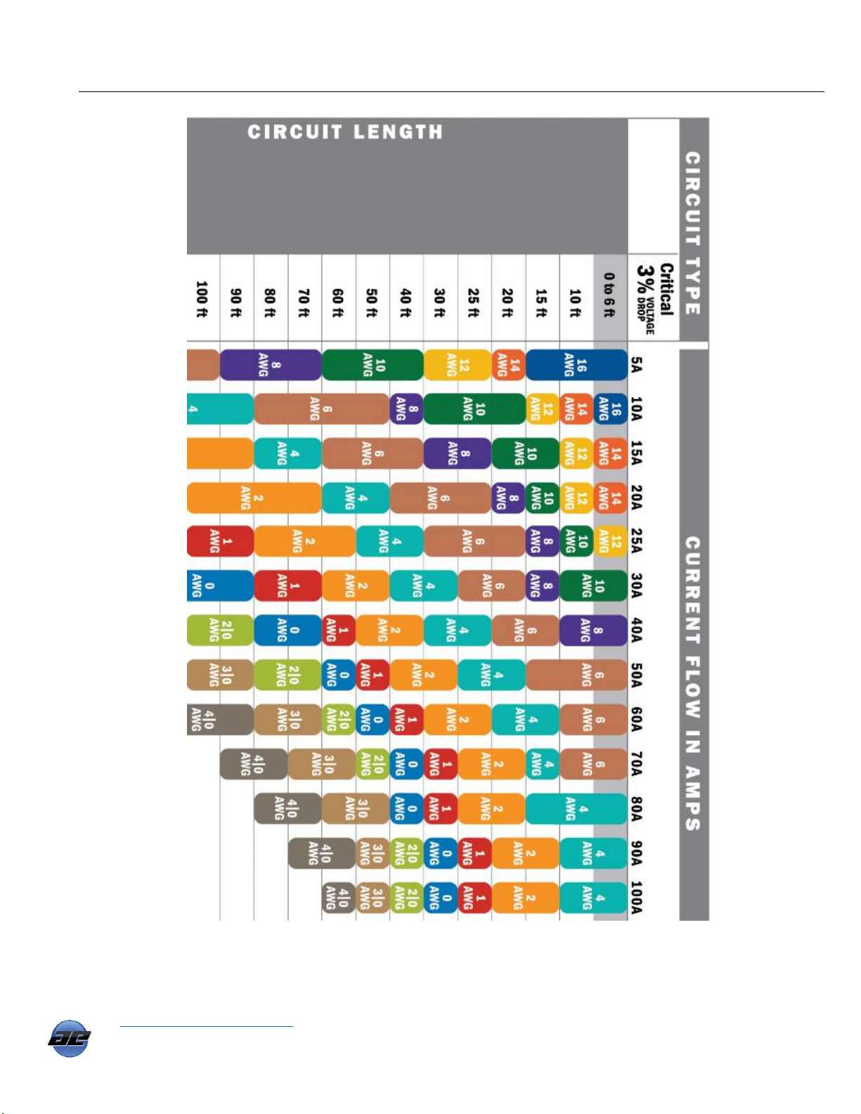
Wire Size Recommendation Chart
www.atkinsonelectronics.com Circuit Board Division
800.261.3602 Revised 05/19
19

Appendix-A
When selecting the correct amperage rating for your in-line circuit breaker, first determine the
maximum current output of your solar panel array by adding up the current at maximum Power (Imp)
for each panel, then round up to the next standard amperage size.
Example: (3) 150watt panels, Imp = 8.5Amps ea. Total Imp. = 25.5Amps
Recommended fuse or circuit breaker size 30 Amps.
In-line Fuse examples (Resettable or Blade type)
Bussman Maxi in-line fuse holder
Part number: HHX (6 Awg wire)
Bussman Maxi Fuse
Available in 20, 25, 30, 35, 40 & 50 Amps
Part number: CB185-XX
XX= Amp rating
Bussman Resettable Circuit Breaker
Available in 20, 25, 30, 35, 40 & 50 Amps
XX=Amp rating
Automotive Audio Resettable Breaker
Available in 20, 30, 40 & 50 Amps
The fuse, fuse holder and circuit breakers are available at any of the major on-line retailers.
20
www.atkinsonelectronics.com Circuit Board Division
800.261.3602 Revised 05/19

Cleaning Tips
Do not spray water or cleaning solution directly to the face plate or LCD of the SEDM6-40. The liquid
could run between the face plate and the LCD on to the circuitry on the SEDM6-40 circuit board causing
damage to the electronics and WILL VOID THE WARRANTY!
Template for the SEDM6-40
21
www.atkinsonelectronics.com Circuit Board Division
800.261.3602 Revised 05/19

Make sure ALL of your connections, from the
solar panel to the battery, are coated in
dielectric grease.
Like Ideal Nolax or Permatex
22
www.atkinsonelectronics.com Circuit Board Division
800.261.3602 Revised 05/19

Limited Warranty
Atkinson Electronics, Inc. gives this express warranty (along with extended warranty endorsements, where applicable)
in lieu of all other warranties, express or implied, including (without limitation), warranties of merchantability and
fitness for a particular purpose. This constitutes Atkinson Electronics, Inc.'s sole warranty and obligation with regard to
our products as well as the customer's sole remedy.
Atkinson Electronics, Inc. expressly disclaims all liability and responsibility for any special, indirect or consequential
damages or any further loss of any kind whatsoever resulting from the use of our product. The customer's sole and
exclusive remedy and the limit of Atkinson Electronics, Inc.'s liability for any loss whatsoever, shall not exceed the
purchase price paid by the customer for the product to which a claim is made.
Countries or States that do not allow limitations of incidental or consequential damages or on how long an implied
warranty lasts, the above limitations may not apply to you. This warranty gives you specific legal rights and you may
also have other rights which vary from State to State or Country to Country.
All products manufactured by Atkinson Electronics, Inc. are warranted to be free from defects in material and
workmanship in accordance with and subject to the following terms and conditions:
1. This warranty is limited to the original customer only. It cannot be transferred or assigned to third parties unless
the intent to transfer to a third party is expressly indicated in a purchase order and/or warranty processing
arrangements have been agreed upon in writing by Atkinson Electronics, Inc.
2. Atkinson Electronics, Inc. will correct any defects in material or workmanship which appear within two (2) years
from the date of shipment by Atkinson Electronics, Inc. (or its authorized distributors) to the original customer.
Atkinson Electronics, Inc. will repair or replace, at our option, any defective products, provided that our
inspection discloses that such defects developed under normal and proper use. This warranty does not extend
to goods subjected to misuse, neglect, accident or improper installation, or to maintenance or repair of products
which have been altered or repaired by anyone except Atkinson Electronics, Inc., unless otherwise stated in
writing. Atkinson Electronics, Inc. will correct any defects in material or workmanship of OEM products
(designated as such in our catalog or web site) which appear within two (2) years from the product date code or
from the factory invoice date, whichever is later.
3. An appropriate charge (25% of product list price) may be made for testing, repairs, replacement and shipping
for a returned product which is not defective or found to be defective as the result of improper use, maintenance
or neglect.
4. Atkinson Electronics, Inc. will not accept responsibility for any invoiced goods or services that are not covered
by an Atkinson Electronics, Inc. written purchase order. Under no circumstances does Atkinson Electronics, Inc.
agree to pay for labor or other related expenses associated with the troubleshooting and/or repair of our product
without prior specific written authorization.
5. Information in our descriptive literature is based on product specifications that are current at the time of
publication.
Product specifications, design and descriptive literature are subject to change as improvements are introduced.
Although we announce changes as they occur, we cannot guarantee notification to every customer. Atkinson
Electronics, Inc. warrants delivered products to conform to the most current specifications, design and descriptive
literature. This warranty policy may be expanded or limited, for particular categories of products or customers, by
information sheets published as deemed appropriate by Atkinson Electronics, Inc.
www.atkinsonelectronics.com Circuit Board Division
800.261.3602 Revised 05/19
23
 Loading...