

Page 1

Wireless G
Router
www.ativasupport.com
Ativa Tech Support
US: 1-866-91-ATIVA (1-866-912-8482)
© 2006 Ativa. All rights reserved. All trade names are registered trademarks of respective manufacturers listed.
Apple, AirPort, Mac, Mac OS, and AppleTalk are trademarks of Apple Computer, Inc., registered in the U.S. and
other countries. Windows, NT, and Microsoft are either registered trademarks or trademarks of Microsoft
Corporation in the United States and/or other countries.
P75234
Page 2
Wireless G
Router
User Manual
AWGR54
Page 3

Page 4

Table of Contents
1. Introduction . . . . . . . . . . . . . . . . . . . . . . . . . . . . . . . . . . . . . . . . . . . . . 1
Benefits of a Home Network. . . . . . . . . . . . . . . . . . . . . . . . . . . . . . . . 1
Advantages of a Wireless Network . . . . . . . . . . . . . . . . . . . . . . . . . . . 1
2. Product Overview . . . . . . . . . . . . . . . . . . . . . . . . . . . . . . . . . . . . . . . . 6
Product Features . . . . . . . . . . . . . . . . . . . . . . . . . . . . . . . . . . . . . . . . . . 6
3. Knowing your Router . . . . . . . . . . . . . . . . . . . . . . . . . . . . . . . . . . . . . 9
Package Contents . . . . . . . . . . . . . . . . . . . . . . . . . . . . . . . . . . . . . . . . . 9
System Requirements. . . . . . . . . . . . . . . . . . . . . . . . . . . . . . . . . . . . . . 9
Easy Install Wizard Software System Requirements . . . . . . . . . . . . . 9
4. Connecting and Configuring your Router . . . . . . . . . . . . . . . . . . . 14
5. Alternate Setup Method. . . . . . . . . . . . . . . . . . . . . . . . . . . . . . . . . . 22
6. Using the Web-Based Advanced User Interface . . . . . . . . . . . . . 37
Changing LAN Settings . . . . . . . . . . . . . . . . . . . . . . . . . . . . . . . . . . . 38
Viewing the DHCP Client List Page . . . . . . . . . . . . . . . . . . . . . . . . . 40
Configuring the Wireless Network Settings . . . . . . . . . . . . . . . . . . 40
Securing your Wi-Fi Network . . . . . . . . . . . . . . . . . . . . . . . . . . . . . . 45
WEP Setup . . . . . . . . . . . . . . . . . . . . . . . . . . . . . . . . . . . . . . . . . . . 50
WPA Setup . . . . . . . . . . . . . . . . . . . . . . . . . . . . . . . . . . . . . . . . . . . 52
Setting WPA/WPA2 . . . . . . . . . . . . . . . . . . . . . . . . . . . . . . . . . . . 53
Using the Access Point Mode . . . . . . . . . . . . . . . . . . . . . . . . . . . . . . 56
Configuring the Firewall . . . . . . . . . . . . . . . . . . . . . . . . . . . . . . . . . . 57
Setting MAC Address Filtering . . . . . . . . . . . . . . . . . . . . . . . . . . . . . 60
Restarting the Router . . . . . . . . . . . . . . . . . . . . . . . . . . . . . . . . . . . . 64
Updating the Firmware . . . . . . . . . . . . . . . . . . . . . . . . . . . . . . . . . . 68
7. Manually Configuring Network Settings . . . . . . . . . . . . . . . . . . . . 76
8. Recommended Web Browser Settings . . . . . . . . . . . . . . . . . . . . . . 81
9. Troubleshooting. . . . . . . . . . . . . . . . . . . . . . . . . . . . . . . . . . . . . . . . . 83
10. Information . . . . . . . . . . . . . . . . . . . . . . . . . . . . . . . . . . . . . . . . . . . 100
Page 5

Page 6

Introduction
Thank you for purchasing the Ativa Wireless G Router (the Router). The following
two short sections discuss the benefits of home networking and outline best
practices for maximizing your wireless home network range and performance.
Please be sure to read through this User Manual completely, and pay special
attention to the section entitled “Placement of your Router for Optimal
Performance” on page 2.
Benefits of a Hom e N etwork
• Share one high -speed Internet connection with all the computers
in your home
• Share resou rces , such as fil es and hard drives among all the connected
computers i n your home
• Share a single prin ter with the ent ire fam ily
• Share docum ents, music , vide o, a nd digital pict ures
• Store, retrieve, and copy files from one computer to another
• Simultaneo usly play ga mes online , check Interne t e mail, and chat
Advan tages of a Wireless Network
• Mobility – you’ll no lon ge r need a dedicated “computer
room”—now you can work on a netw orked lapt op or desktop co mputer
anywhere within your wireless range
• Easy ins tallati on – The Ativa Easy Installation Wizard makes
setup simple
• Flexi bility – set up and access printers, c omputers, and other networking
devices fro m a nywh ere i n your home
• Easy expan sion – the wide range of Ativa network ing products le ts
you expand you r n etwork to inc lude devices such as printers a nd
gaming cons oles
• No cabling required – you can spare the expense and hassle of
retrofitting Ethernet cabling throu ghout the hom e o r office
• Widespread industry acceptanc e – choose from a wide range of
interope rabl e n etworki ng products
sectio n
1
2
3
4
5
6
7
8
9
10
1
Page 7

Introduction
Placement of your Router for Optimal Performance
Important Factors for Placement and Setup
Your wireless connection will be stronger the closer your co mputer is to your
Router. Typical indoor operating range for wireless de vices is betw een 100 and
200 feet.
In the same way, your wireles s c onnecti on and performance will degrade
somewhat as the distance between your Rout er and connec ted device s
increase s. This may or may not be notic eable to you. As you move far ther
from your Router, connec tion speed may dec re ase. Fac tors that can weak en
signals simply by get ting in the way of your ne twork’s radio waves are metal
appliances or obstruc tions, an d walls .
If you have concern s a bout your network’s perfor mance that mi ght be related
to ran ge or ob struction fact ors, try moving the computer to a position
between five a nd 10 fe et away from the Router in order to see if distance is
the problem . If difficulties persist even at clo se range, please contact Ativa
Technical Support .
Note: Whi le some of the items listed below can affect network performance,
they will not prohibit your wirele ss network from functioning; if you are
concerned that your netw ork is not operating at its maximum effective ness,
this checklist may hel p.
1. Wireless Router Placement
Place your Route r, the ce ntral connection point of your network , as close
as possible to the center of your wi re less netwo rk devices .
To achie ve the best wireless network cove rage for your “ wireless clients”
(i.e., c omputers ena bled by Ativa Wireless Notebook Network Cards,
Wireless Desktop Network Card s, and Wireless USB Adapters):
• Ensure that yo ur Ro uter’s networking antennas are parallel to each
other, and are positioned vertically (toward the ceili ng). If your
Router itself is positioned vertically, poin t t he antenna s a s much as
possible in an upward direct ion.
• In multistory homes, pl ace the Router on a floo r t hat is as close
to the center of the ho me as possibl e. This may mean pla cing the
Router on an upper floor.
• Try not to place the Ro uter near a cordless phone.
2
Page 8

Introduction
2. Avoid Obstacles and Interference
Avoid pl acing your Router near devices that may e mit radio “no ise,”
such as microwave ovens . Dense obje cts that can inh ibit wireless
communic ation incl ude:
• Refrigerators
• Washers and /or drye rs
• Met al cabinet s
• Large aquari ums
• Met allic-based , UV-tinte d w indows
If your wireless sig nal seems wea k i n s ome spots, make sure that ob jects
such as these are not blocking the signal ’s path (b etween your computers
and Router).
3. Cordless Phones
If the performance of your wireles s n etwork is imp aired after att ending
to the above issu es, and you have a cordless ph one:
• Try mo ving cordless phones away from the Rout er and your
wireless -enabled computers.
• Unp lug and remove the ba ttery from any cordless phone that operate s
on the 2.4GHz band (check the manufacturer’s in fo rmation ). If this
fixes the proble m, your phon e m ay
be interfering.
• If you r p hone suppo rts ch annel selection, change the chan nel on
the phone to the far thest channel from your wireless network. For
example, change the phone to chann el 1 a nd move your Router to
channel 11. See your pho ne’s user ma nu al fo r d etailed in struction s.
• If nec essary, conside r s witching to a 900MHz cordles s p hone.
sectio n
1
2
3
4
5
6
7
8
9
10
4. Choose the “Quietest” Channel for your Wireless Network
In locations where home s o r offices are close together, suc h a s a partm ent
buildings or office complexes, there may be wirele ss network s n earby
that can conflict with yours.
Use the Site Su rvey capabil ities found in the wi re less utili ty of your
wireless ad apter or card to locate any oth er wireless net works that are
avail able (see your wireless adapter’s o r c ard’s user manual), and move
your Router and com puters to a chan nel as far away from other networks
as possible.
3
Page 9

Introduction
• Experiment with more than one of the available channels in order to
find the clearest connection and avoid interference from neighboring
cordless phones or other wireless devices.
• For Ativa wireless networking products, use the detailed Site Survey and
wireless channel information included with your Wireless Network Card
or Adapter. See your Network Card’s user guide for more information.
These guidelines should allow yo u t o c over the maximu m p ossible area
with your Router.
5. Secure Connections, VPNs, and AOL
Secure conn ections ty pically require a user name and password , and are
used where securit y i s i mportant . Secure con nection s i nclude:
• Virtual Privat e N etwork (VPN) connections, often used to connect
remotely to an office ne twork
• The “Bring Your Own Access” progra m f ro m America Online (AO L),
which lets you us e AOL throu gh broadband provided by anoth er cable
or DSL service
• Mos t o nline bank ing websit es
• Many com mercial websites that require a user name and password to
access your account
Se cure connect ions can be inte rrupted by a compu ter’s power
management setting , which causes it to “go to sleep.” The simpl est
solution to avoid this is to simp ly reco nnect by rerunnin g t he VP N or AOL
software, or by re-logging into the secure websi te.
A sec ond alternative is to chan ge your co mputer’s power management
settings so it does not go to sleep; however, this may not be appro priate
for portable computers. To ch ange your power manage ment setti ng under
Windows, see the “Power Opt ions” item in the Control Panel.
If you continue to have diffic ulty with Secure Connec tions, VPNs , and
AOL, p lease review th e s teps above to be sure you have add ressed
these issues.
4
Page 10

Introduction
For more information regarding our networking products, visit our website at
www.ati vasu pport .com or call Ativa Technical Support at:
US: 1-866-91-ATIVA (1-866-912-8482)
sectio n
1
2
3
4
5
6
7
8
9
10
5
Page 11

Product Overview
Product Features
In minutes you will be able to share your Inte rnet conne ction and net work
your comput ers. The following is a list of features that ma ke your new Ativa
Wireless G Router an ideal soluti on fo r your home or small office network.
Works with Both PCs and Mac® Computers
The Router supports a variety of networking environments including Mac
OS® X v 10.x, Apple Talk®, Linux®, Windows® 98, Me, NT®, 2000, an d XP, and
others. All that is needed is an Internet browse r a nd a n etwork ada pter that
suppor ts TCP/ IP (the stand ard language of the Inter net).
Front-Panel LED Display
Lighted LEDs on the front of the Router ind icate whic h f unction s a re in
operation. You’ll know at-a-gla nce whether your Router is connected to
the Internet. This feature elim inates the ne ed fo r a dvan ced software and
status-monitori ng procedures.
Web-Based Advanced User Interface
You can set up the Rout er’s advanced functions easily throu gh your web
browser, without having to insta ll additio nal software onto the computer.
There are no disks to ins tall or keep track of an d, best of all, you can make
changes and pe rform setup fun ctions from any comp uter on the netw ork
quickly and easily.
NAT IP Address Sharing
Your Router em ploys Network Address Translatio n ( NAT) to share the single
IP address ass igned to you by your Internet Service Provider whil e s av ing the
cost of adding IP ad dresses to your In ternet ser vice account.
SPI Firewall
Your Router is eq uipped wit h a fi rewall that will protect yo ur network from a
wide array of common hac ker attacks includ ing IP Spoofing, L and Attack, Ping
of D eath (PoD), De nial of Service (DoS), IP with ze ro length, Smu rf Attac k, TCP
Null Scan, SY N f lood, UDP flooding, Tear Drop Attack , ICMP defect, RIP defec t,
and fragment flo oding .
6
Page 12

Product Overview
Integrated 10/100 4-Port Switch
The Router has a built-in, 4-port network switch to allow yo ur wired
computers t o s hare printers, data and MP3 files, digital photos, and muc h
more. The swi tch features automatic dete ction so it will adjust to the spee d of
connected devices. The switc h will transfer data be tween comp uters and the
Internet simultaneou sly without interrupting or consuming re sources.
Universal Plug-and-Play (UPnP) Compatibility
UPnP (Unive rsal Plug-and-Play) is a tec hnology th at offers se amless ope rati on
of v oice messa ging, v ideo messa gi ng, games, and other applications that are
UPnP-compliant.
Support for VPN Pass-Through
If you connect to yo ur office network from home using a VPN connection,
your Router will al low your VPN-equipped computer to pass through the
Router and to your offic e n etwork.
1
sectio n
2
3
4
5
6
Built-In Dynamic Host Configuration Protocol (DHCP)
Built-In Dyna mic Host Configurati on Protocol (DH CP) on-boa rd makes for
the easiest possible connection of a net work. Th e D HCP server will assign
IP addresse s t o e ach computer automatically so there is no need for a
complicated networking setup.
Easy Install Wizard
The Easy Insta ll Wi zard takes the guesswork out of sett ing up your Router.
This automatic soft ware dete rmines you r network settings for you and sets up
the Router for connection to your Int ernet Serv ice Provider (I SP). In a matter
of m inutes, you r Wireless Router will be up and running on the In ternet.
NOTE: Easy Install Wizard software is compa tible with Wind ows 98SE, Me,
2000, an d XP; and Mac OS X. If you are using an other operatin g s ystem, the
Wireless Router can be set up using the Alternate Setup Method describe d i n
this User Manu al (see page 22).
7
7
8
9
10
Page 13

Product Overview
Integrated 802.11g Wireless Access Point
802.11g is an exc iting new wirel ess tech nology tha t a chieves da ta rates up to
54Mbps, nearly five times fa ster than 802 .11b.
MAC Address Filtering
For ad ded security, you can set up a list of MAC address es (unique cl ient
identifiers) that are allo wed access to your ne twork . Every co mputer has it s
own MAC address. S imply enter the se MAC addresses int o a li st using the
Web-B ased Advan ced User Inte rface and you can con trol access to
your networ k .
8
Page 14

Knowing your Router
Package Contents
• Ativa Wireless G Router
• Quick Installation Guide
• Ativa Easy Install Wizard Software CD with User Manua l
• Ativa RJ45 Ethernet Networking Cab le
• Pow er Supply
System Requirements
• Broadban d I nternet co nnectio n s uch as a cable or DSL modem with
RJ45 (Ethernet) connection
• At least one computer with an installed network in terface adapter
• TCP/IP networking protocol ins talled on eac h computer
• RJ45 Ethernet networking cable
• Internet browser
Easy Install Wizard Software System Requirements
• A PC running Wi ndows 98SE , Me, 2000, o r XP; or a Mac com puter
running Mac OS X
• Minimum 64M B R AM
• Internet browser
1
2
sectio n
3
4
5
6
7
8
9
10
9
Page 15
Knowing your Router
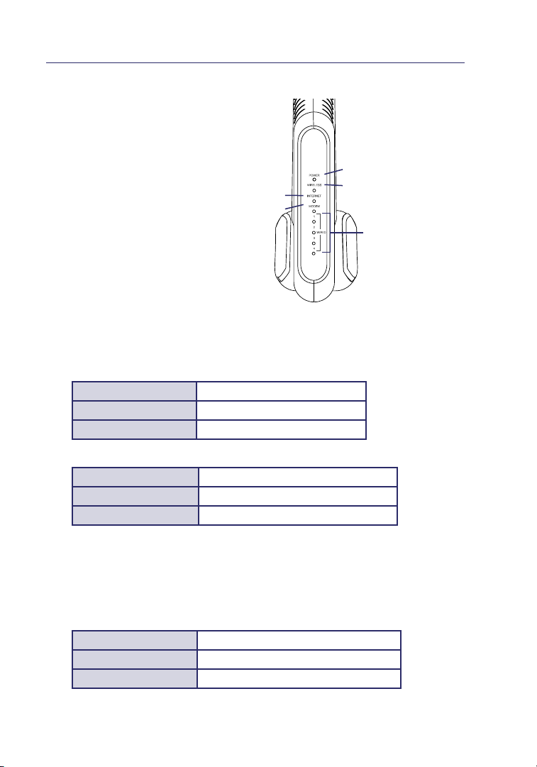
The Router has been designed to
be placed on a desktop. All of the
cables exit from the rear of the
Router for better organiz ation and
utility. The LED indicators are easily
visible on the front of the Router to
provide you with info rmation ab out
network activity and status.
(5)
(4)
1. Power/Ready LED
When you apply power to the Router or restart it, a short peri od of time
elapses whi le the Router boot s u p. D uring this time, the Power/Ready LED
blinks. When the Router ha s c omplete ly booted up, the Power/ Re ady LED
becomes a SO LID light, indi cating the Rout er is re ady for us e.
OFF Router is OFF
Blinking Blue Router is Booting Up
Solid Blue Router is Ready
2. Wireless Network LED
OFF Wireless Network is OFF
Blue Wirel ess Networ k i s Rea dy
Blinking Blue Indicates Wireless Activit y
(1)
(2)
(3)
3. Wired Computer Status LEDs
These LEDs are labeled 1–4 and correspond to the numbered ports on the
rear of the Router. When a computer is properly connected to one of the
wired computer ports on the rear of the Router, the LED will light. BLUE
means a 10/100Base-T device is connected. When information is being sent
over the port, the LED blinks rapidly.
OFF No Device is Lin ked to the Port
Blue 10/100Bas e-T Dev ice Conn ected
Blinking Blue Port Activity
10
Page 16

Knowing your Router
4. Modem Status LED
This LED lights in BLUE to indic ate that your mo dem is connec ted
properly to the Route r. It bli nks rap idly when information is being sent
over the por t between the Router and the modem.
OFF No WAN Link
Solid Blue Good WAN Link
Blinking Blue WAN Acti vity
5. Internet LED
This unique LED shows you when the Router i s c onnecte d t o t he
Internet. When the light is O FF, the Router is NOT co nnected to th e
Internet. When the light is blinking, th e Rou ter is attemp ting to conne ct
to the Internet. When the ligh t i s s olid BLUE, the Router is co nnected
to the Internet. When using th e “Disconnect after x minutes” feature,
this LED becomes extreme ly us eful in monit oring the statu s o f your
Router ’s connec tion.
OFF Router is not Connecte d t o t he Interne t
Blinking Blue
Solid Blue Router is Co nnected to th e I nternet
Router is Atte mpting to Connect to
the Internet
1
2
sectio n
3
4
5
6
7
8
9
10
11
Page 17

Knowing your Router
(6)
(7)
(8)
(9)
Res et butt on i s
loc ated on the
side of the unit .
6. Power Jack
Conne ct the includ ed 5V DC power supp ly to this jack.
7. Connections to Computers (Wired Computer Ports)
Conne ct your wired (non -wireless ) c omputers to the se ports. These po rts
are RJ45, 10/ 100 auto-n egotiatio n, auto-u plinkin g p orts for stan dard UT P
category 5 or 6 Ethernet cable. The port s a re la beled 1 through 4. These por ts
correspo nd to the numbered LEDs on th e f ront of the Router.
8. Connection to Modem (Modem Port)
This port is for con nection to your ca ble or DSL modem. Use the cable that was
provided wi th the modem to con nect the mode m t o t his port . Use of a cable
other than the cable supplied with the cable modem may not work properly.
12
Page 18

Knowing your Router
9. Reset Button
The “Rese t” button is used in rare case s whe n t he Ro uter may functi on
improper ly. Resetting the Router will restore th e Rou ter’s n ormal
operation while ma intaini ng the programmed sett ings. You can als o
restore the factor y d efault setti ngs by using the “Reset” butto n. Use
the restore opti on in instanc es wh ere you may h ave forgotten your
custom password.
a. Resetting the Router
Push and relea se the “Reset ” button. The lights on the Router
will momentarily flash. The Po wer/Ready ligh t w ill begin to
blink. When the Power/Ready lig ht becomes solid again, t he
reset is compl ete.
b. Restoring the Factory Defaults
Press and hold th e “Reset” button fo r a t l east 10 secon ds, then
release it. The lig hts on the Router wil l m omentarily flash. The
Pow er/Ready light wi ll begin to blink. When the Power/Ready light
becomes s olid again, the restore is compl ete.
1
2
sectio n
3
4
5
6
7
8
9
10
13
Page 19

Connecting and Configuring your Router
Verify the contents of your box. You should have the following:
• Ativa Wireless G Router
• Quick Installation Guide
• Ativa Easy Install Wizard Software CD with User Manua l
• RJ45 Ethernet Networking Cable (for co nnectio n of the
Router to the computer)
• Pow er Supply
• Wireless Securi ty Setup Guide
Modem Requirements
Your cabl e o r D SL modem must be equi pped with an RJ4 5 E thernet po rt. Many
modems have both an RJ45 Ethernet port and a USB connection. If you have
a modem with both Ethernet and USB, and are usin g t he USB connec tion at
this time, you w ill be instructed to use the RJ45 Ethernet port during the
installation proce dure. If your mod em has only a USB port , you can req uest a
different type of modem from yo ur ISP, or you can , in some cas es, purchas e a
modem that has an RJ45 Ethernet port on it .
Ethernet USB
ALWAYS INSTALL YOUR ROUTER FIRST! IF YOU ARE INSTALLING
NUMEROUS NETWORK DEVICES FOR THE FIRST TIME, IT IS IMPORTANT THAT
YOUR ROUTER IS CONNECTED AND RUNNING BEFORE ATTEMPTING TO
INSTALL OTHER NETWORK COMPONENTS SUCH AS NOTEBOOK CARDS AND
DESKTOP CARDS.
Easy Install Wizard
Ativa has provided our Easy Install Wi zard software to make insta lling your
Router a simple and easy task. You can use it to get your Rout er up and
running in minut es. The Easy Install Wizard requires that yo ur Windows 98SE,
Me, 2000 , or XP; or Mac OS X v10.1.x co mputer be con nected direc tly to your
cable or DSL modem and that the Internet connection is active and workin g
at the time of insta llation . If it is not , you must use the “Alternate Setup
Method” se ction of this User Manual to configure your Router. Add itional ly, if
you are using an operati ng system oth er than Windows 98 SE, Me, 2000, or XP,
you must set up the Router using the “Alternate Setup Method” sectio n of this
User Manual .
14
Page 20

Connecting and Configuring your Router
IMPORTANT: Run the Easy Install Wizard software from the computer that
is directly connected to the cable or DSL modem. DO NOT CONNECT THE
ROUTER AT THIS TIME.
Step 1 Run the Easy Install Wizard Software
1.1 Shut down any progra ms that are running on you r c omputer at th is time.
1.2 Mak e sure you have th e fol lowing ite ms at the comput er that is now
directly conn ected to the cab le or DSL modem. D O NOT CONNECT TH E
ROUTER AT THIS TIME.
• Quick Ins tallati on Guide
• The Easy Instal l Wizard S oftware CD with User Manual
• The Router
• The Router ’s Power Supply
• RJ45 Ethernet Networking Cable
1.3 Turn off any firewall or Inter net-connection-sha ring software
on your comput er.
1.4 Ins ert the Easy Ins tall Wizard software CD into yo ur CD-ROM drive.
The Easy Insta llation Wiza rd scre en will automatically app ear on your
screen with in 15 seconds . If it does not , selec t your CD-ROM drive from
“My Com puter ” and double -clic k on the file nam ed “EasyInstall.exe”
on the CD-ROM.
1
2
3
sectio n
4
5
6
7
8
9
10
15
Page 21
Connecting and Configuring your Router
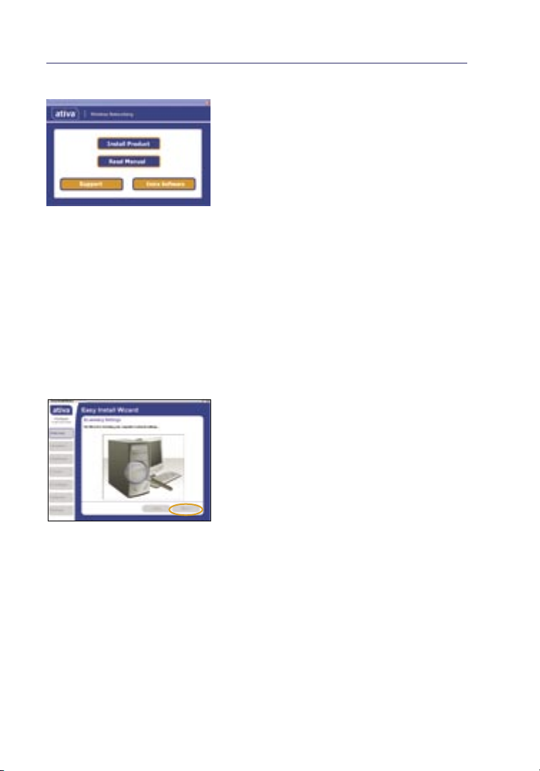
Welcome Screen
After you ins ert the CD in to your
CD-ROM drive, the Wi zard ’s welcom e s creen
will appear. Make su re you have not co nnected
the Router at this point. If you have
connected your Router, please reco nnect your
computer directly to the mode m. Click “Run
the Easy Insta ll Wi zard” wh en you are re ady t o
move on.
Progress Screen
The Easy Insta ll Wi zard will show you a
progress screen each time a step in the set up
has been completed. Eac h time you see the
progress screen, click “Next” when you are
ready to move to the next step.
Examining Settings
The Wizard will now exam ine your comp uter’s
network settings and gather informatio n
needed to complete the Router’s co nnectio n
to the Internet. When the Wizard is fini shed
examining your comput er, cl ick “N ext”
to continue .
Multiple Network Adapters Found Screen
If you have more than one netw ork adapte r
installed in your comput er, th is screen will
appear. If you have more than one ne twork
adapter installed in you r c omputer, you
must design ate for the Wizard which adapt er
is connected to your modem. To do this,
select it from th e l ist and click “Next ”. If
you are not sure which adapter to choose,
select the adapter at the top of the li st. If
you mistake nly choose th e w rong adapter
now, you wil l b e a ble to choose a differe nt
one later.
16
Page 22
Connecting and Configuring your Router
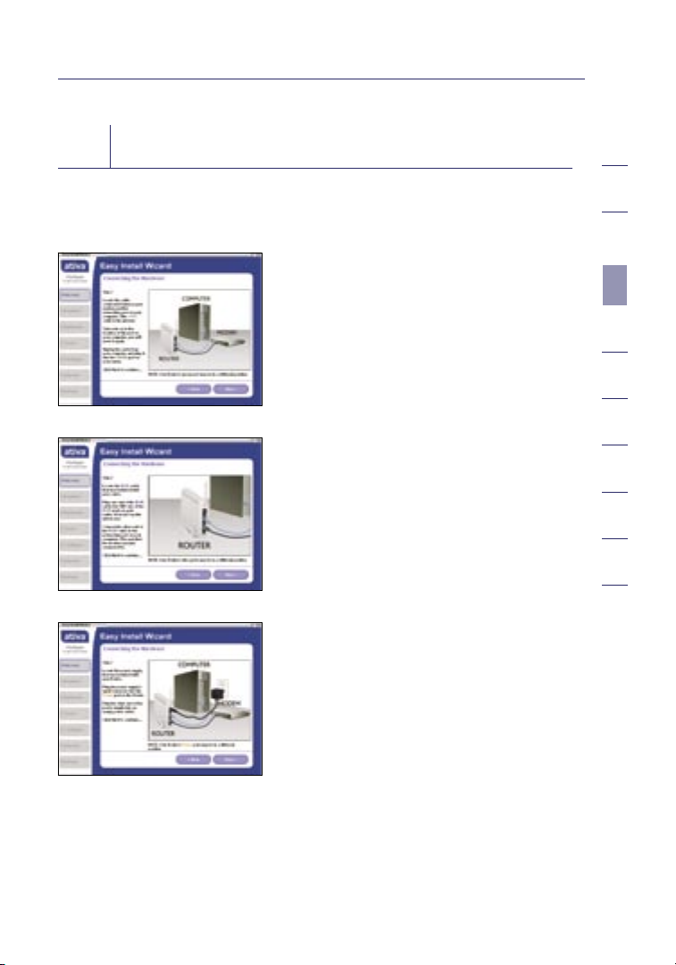
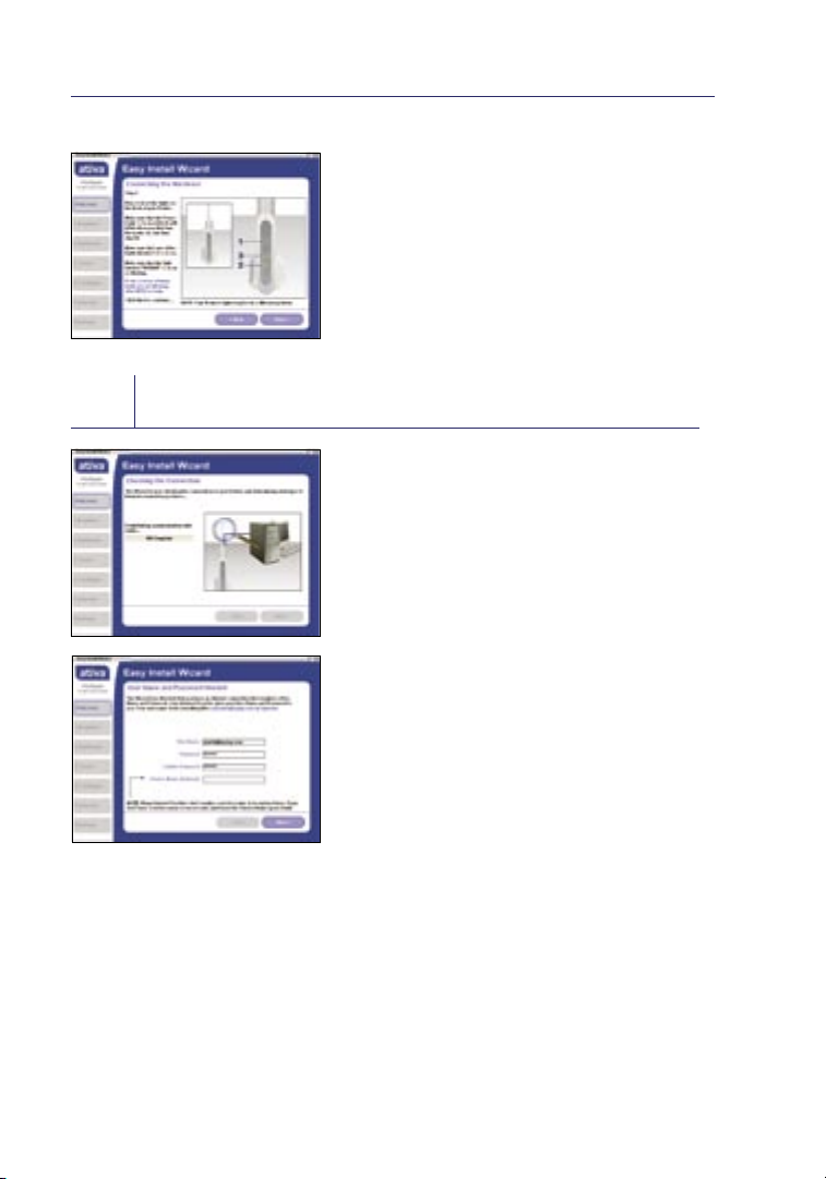
Step 2 Set up the Hardware
The Wizard will walk you through connecting your Router to your computer and
modem. Follow the steps on the screen using the pictures as a guide.
2.1 This step instructs you to locat e
the cable connected between your
modem and the networking port on
your comput er. Un plug this cab le
from the compu ter and plug it int o
the modem port on the Router. Click
“Next” to con tinue.
2.2 This step instructs you to locat e
the BLUE cable that is included
with your Router. Plug on e e nd
of t his cable int o AN Y o ne of the
wired-co mputer por ts on your
Router. Plug the other end of t he
cable into the networking port on
your comput er. C lick “ Next”
to continue .
2.3 This step ins tructs you to locate the
power supply t hat is includ ed with
your Router. Plug the pow er supply’s
small connector into the power port
on the Router. Plug the powe r s upply
into an empty power outlet. Click
“Next” to con tinue.
1
2
3
sectio n
4
5
6
7
8
9
10
17
Page 23
Connecting and Configuring your Router
2.4 This step instructs you to look at the
lights on the fro nt of yo ur Ro uter. Make
sure the appropria te lights are ON. Refer
to the Easy Insta ll Wi zard software on
your comput er’s screen for more detail s.
Click “Next” to con tinue.
Note : The Easy Install Wiza rd may ask
you to reboot your com puter. If it does,
reboot your computer and proceed with
the installation.
Step 3 Check the Connection
3.1 Onc e you have co mpleted co nnectin g
the Router, the Wizard will ch eck the
connection to the Router and then go
on to determine what type of Intern et
connection you have.
3.2 User Name and Password N eeded
If you have a c onnecti on type that
requires a user nam e a nd a p assword, the
Wizard w ill ask you to type in your us er
name and password. If your conn ection
type does not req uire a u ser name and
password, yo u w ill not see this sc re en.
Your user name and password is provided
to you by your Internet Service Provider.
If you have to type in a user name an d
password to conn ect to the Inter net,
then type that same user name and
password in here. Your us er name looks
something like “jsmith @myi sp.com” or
simply “j smith”. The service name is
optional and is very rarely req uired by
your ISP. If you don’t kn ow your service
name, le ave this blank. When you have
entered your infor mation, click “Next”
to move on.
18
Page 24
Connecting and Configuring your Router
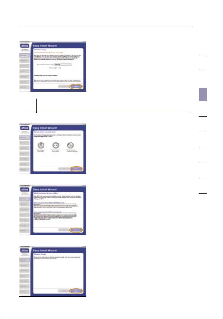
Step 4 Secure your Network
3.3 Wir eless Setu p
This step is op ti onal.
Click “Next” if you want to skip it .
Using thi s s tep, you can cust omize your
wireless ne twork sett ings if you want
to. Follow the steps on the screen to
complete this step. Click “N ext”
to continue .
4.1 After connection has been established,
you will be prompted by t he Ea sy
Install Wiz ard to select your desi re d
security le vel.
4.2 WEP an d WPA are the two securit y
options. If you do not want security or
would prefer to install at a later time,
click the radi o b utton next to “NONE”
and click “Next .”
4.3 The Wi-Fi Protected Acc ess (WPA)
security op tion features a two- password
setup. You can select one password
that provid es COM PLETE NETWOR K
access and ano ther passw ord for GUE ST
(Internet only) access only. Clic k “Next”.
1
2
3
sectio n
4
5
6
7
8
9
10
4.4 Sec urity setup is now co mplete. Click
“Next” to con figure.
19
Page 25
Connecting and Configuring your Router
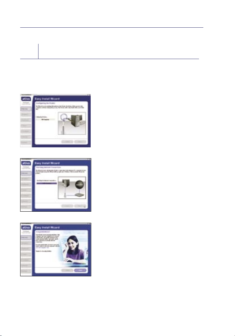
Configure the Router
Step 5
The Wizard will now transfer all of the configuration information to the Router.
This will take approximately one minute. During this time, do not turn off the
Router or computer. The Router will restart itself at the end of this step.
5.1 Checking Internet
The Wizard will now ch eck for an Internet
connection. Thi s c an take a few minutes.
The Wizard may n ot detect a conn ection
right away. If not, it wil l ret ry a number
of t imes. The “Connected” l ight on the
front panel of the Router will flash
during this ti me. Pleas e b e p atient
through thi s p ro cess.
5.2 Finished
When the Internet connection is
complete, the Wizard will tell yo u t hat
you are finished. The “Conne cted” LED
on the front of the Router will be solid
BLUE, in dicatin g t hat the Router is now
connected to the Internet.
Your Rou ter is now con nected to the Interne t.
Now you can begin surfin g the I nternet by
opening your browser and going to your
favorite web page.
20
Page 26

Connecting and Configuring your Router
Congratulations. You have finished installing your new Ativa Router. You
are ready to set up the ot her com puters in your h ome. You can also add
computers to your Router any time yo u wa nt.
1
2
3
sectio n
4
5
6
7
8
9
10
21
Page 27

Alternate Setup Method
The We b-Based Advanced User Interface is a web- based tool th at you can use
to set up the Router if you don’t want to use the Eas y I nstall Wizard. You can
also use it to manage a dvan ced functi ons of the Router. From th e Web-B ased
Advan ced User Inte rface, you can perform the fo llowing ta sks:
• View the Rout er’s cu rrent settings and status
• Confi gure the Router to connect to your ISP wit h t he setting s t hat they
provided you
• Change the current network settings suc h as the Internal IP address, t he
IP address poo l, DHCP settings, and more
• Set the Router ’s firewall to work wi th specifi c a pplicat ions
(por t forwardin g)
• Set up securit y features such as client restricti ons, MAC address fi ltering ,
WEP, and WPA
• Enable the DMZ feature for a single comput er on your netwo rk
• Change the Router’s int ernal pass word
• Enable /Disab le UPnP (Univ ersal Plug-a nd-Play)
• Reset the Router
• Back up your co nfiguration settings
• Reset the Router ’s default settings
• Update the Router’s f irmware
Connect your Router
Step 1
1.1 Turn off the pow er to your modem by unpl ugging the po wer supply from
the modem.
1.2 Loc ate the network cable that is connected between your mode m a nd
your comput er and unplug it from yo ur compute r, leavi ng the other end
connected to your modem.
1.3 Plug the loose end of the cable you just unplu gged into the po rt on the
back of the Route r l abeled “Modem”.
1.4 Connect a new network cable (not included) from the bac k of the
computer to one of t he wired computer ports labeled “1–4”. N ote: It
does not matter which numbe re d p ort you choose.
22
Page 28
Alternate Setup Method
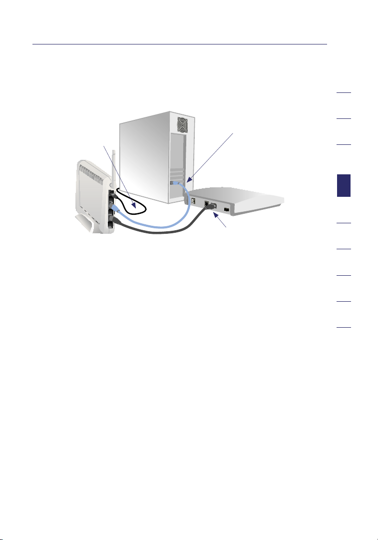
1.5 Turn you r c able or DSL mode m o n by rec onnecti ng the power sup ply
to the modem.
Mac or PC computer that was originally connected
to the cable or DSL modem
Network cable
(to computer)
To power adapter
Existing networking cable
(came with modem)
Note : Your Router may have ports in different locations than depicted
in the illustrat ion above.
1.6 Before plu gging the pow er cord in to the Router, plug the cord into the
wall, then plug the cord into the Router’s pow er jack.
1.7 Verify th at your modem is connected to the Router by c hecking the
lights on the front of the Router. The BLUE light labeled “Modem”
should be ON if you r m odem is conne cted correct ly to the Router. I f i t
is not, rechec k your connections.
1.8 Verify th at your computer is connected properly to the Route r by
chec king the ligh ts labeled “1–4”. The light th at corresponds to the
numbered port connect ed to your compu ter should be ON if you r
computer is connected properly. If it is not, recheck your connections.
1
2
3
4
sectio n
5
6
7
8
9
10
23
Page 29
Alternate Setup Method
Step 2
Set up your Computer’s Network Settings to
Work with a DHCP Server
See the section in this User Manu al called “ Manually Configurin g N etwork
Settings” fo r d irections .
Step 3
Configure the Router Using the Web-Based
Advanced User Interface
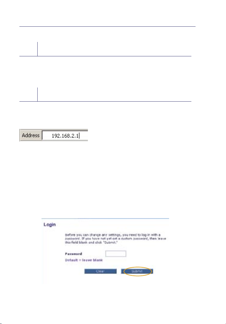
Using your Int ernet browser, you ca n a ccess the Router’s Web-Bas ed Advanced
User Interface. In your brow ser, type “192 .168.2. 1” (you do not need to type
in anything else such as “http://” or “www” ). Then press the “Ente r” key.
PLEASE NOTE: If you have difficulty accessing th e Rou ter ’s Web-Based
Advan ced User Inte rface, go to the secti on entitle d “Manually Config uring
Network Settings”.
Logging into the Router
You will see th e Rou ter’s home page in your browse r w indow. The home page
is visible to any user who wants to see it. To make any changes to the Router’s
settings, you have to log in. Clicking the “Login” button or clicking on any one
of t he links on the hom e p age w ill take you to the login scree n. The Router
ships with no password entered. In the logi n s creen, leave the password blank
and click the “Sub mit” button to log in.
24
Page 30
Alternate Setup Method
Logging out of the Router
One computer at a time can log into the Router for the purp oses of making
changes to the se ttings of the Router. Once a us er has logged in to make
changes, there are two ways that th e c omputer ca n b e l og ged out. Clicking the
“Logout” butto n w ill log the comput er out . The second method is automatic.
The login will time out after a specified period of time. The default login
time -out is 10 minutes . This can be ch anged from 1 to 99 minutes. For more
information, see the section in this manu al entitle d “Changin g t he Logi n
Time-Out Se tting”.
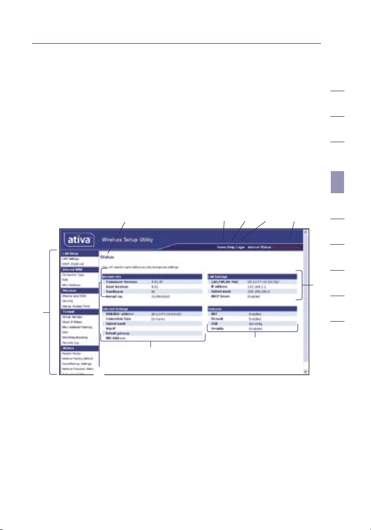
Using the Web-Based Advanced User Interface
The home page is the first page you wi ll see when you access the Web-Based
Advan ced User Inte rface (UI). The home page shows you a qui ck view of the
Router ’s status an d s ettings . A ll adva nced setup pa ges can be reached from
this page.
(10) (2) (5) (4) (3)
(1)
(7)
(8)
(6)
1
2
3
4
sectio n
5
6
7
8
9
10
(9)
1. Quick-Navigation Links
You can go directly to any of the Router ’s UI pages by clicking directly
on these links. The link s a re di vided into logica l c ategories and grouped
by t abs to make find ing a particular setting easier to find. Clicking on
the purple heade r of each tab will show you a s hort des cription of the
tab’s function.
25
Page 31

Alternate Setup Method
2. Home Button
The “Ho me” button is available in every page of the UI. Press ing this
button will take you back to th e h ome page.
3. Internet Status Indicator
This indicator is visible in all pages of the UI, ind icating th e c onnecti on
status of the Route r. When the indicator says “con nection O K” i n
GREEN, t he Ro uter is conne cted to the Inte rnet. When the Router is not
connected to the Internet, the indicator will read “n o c onnecti on” in RED.
The indicator is automatically upd ated when you make changes to the
settings of th e Rou ter.
4. Login/Logout Button
This button enables you to log in and out of th e Rou ter with the press of
one button. When you are logged into the Router, this butt on will cha nge
to read “Logout”. Logging into the Router will take you to a s eparate
login page where you must enter a password. When you are logged into
the Router, you can make changes to the settings. Whe n y ou are f inished
making changes, you can log out of th e Router by clicki ng the “Logout”
button. For more information about logging into the Router, s ee the
section called “L og ging into the Rout er”.
26
Page 32

Alternate Setup Method
5. Help Button
The “He lp” button gives you acc ess to the Router’s help pages . Help is
also available on many pages by cl icking “more info” next to cer tain
sections of ea ch page.
6. LAN Settings
Shows you the set tings of the Loc al Area Network (LAN) side of the
Router. Changes can be mad e t o t he setting s by clicking on any one of
the links (IP Address, Subnet Ma sk, D HCP Server) or by cli cking th e “L AN”
“Quick Navigation” link on the left side of th e s creen.
7. Features
Shows the status of the Router ’s NAT, fi re wall , and wi re less features.
Changes can be made to the settings by cl ickin g o n a ny one of the li nks
or by c licki ng the “Quick Navigatio n” links on th e l eft side of the scree n.
8. Internet Settings
Shows the settings of the Inte rnet /WAN side of the Route r t hat connec ts
to the Internet. Changes to any of these set tings can be made by cli cking
on the links or by clic king on the “Intern et /WAN” “Qui ck Navigation” link
on the left side of the sc reen.
9. Version Info
Shows the firmware version, boot-cod e v ersion, hardware version, and
serial number of the Router.
10. Page Name
The page you are on can be identi fied by this nam e. This User Ma nual will
sometimes refer to pages by name. For instance “L AN > LAN Settings”
refers t o t he “LAN Settin gs” page.
1
2
3
4
sectio n
5
6
7
8
9
10
27
Page 33

Alternate Setup Method
Step 4
Configure your Router for Connection to your
Internet Service Provider (ISP)
The “In ternet /WAN” tab is where you wil l s et up your Router to connect
to your Intern et Service Provider (ISP). The Router is capable of connecting
to virt ually any ISP’s system provided you have cor rectly configured the
Router ’s settin gs fo r your ISP’s conn ection typ e. Your ISP connection settings
are provided to you by your IS P. To configure the Router with the settings
that your ISP gave you, click “Connect ion Type” (A) on the lef t s ide of the
screen. Se lect the conn ection typ e you use. If your ISP gave you DNS settings,
clicking “DN S” (B) allo ws you to enter DNS ad dress entries for ISPs th at
require speci fic settin gs. Clic king “ MAC a ddress” (C) will let you clo ne your
computer’s MAC add re ss or type in a specif ic WAN MAC address, if requi red
by y our ISP. Whe n you have finished making settings, the “Intern et Status”
indicator will read “connection OK” if your Router is set up properly.
(A)
(B)
(C)
28
Page 34

Alternate Setup Method
Setting your Connection Type
From the “Connection Type” page, you can select the type of connection you use.
Select the type of connection you use by clicking the button (1) next
to your connection type and then clicking “Next” (2).
(1)
(2)
1
2
3
4
sectio n
5
6
7
8
9
10
29
Page 35

Alternate Setup Method
Setting your Internet Service Provider (ISP) Connection Type to Dynamic IP
A dynamic connection type is the most common connection type used with cable
modems. Setting the connection type to “dynamic” in many cases is enough to
complete the connection to your ISP. Some dynamic connection types may require
a host name. You can enter your host name in the space provided if you were
assigned one. Your host name is assigned by your ISP. Some dynamic connections
may require that you clone the MAC address of the PC that was originally
connected to the modem.
Change WAN MAC Address
If your ISP requires a specific MAC address to connect to the service, you can
enter a specific MAC a ddress or clone the current computer ’s MAC address
through thi s l ink .
30
Page 36

Alternate Setup Method
Setting your Internet Service Provider (ISP) Connection Type
to Static IP
A static IP address connection type is less common than other connection types.
If your ISP uses static IP addressing, you will need your IP address, subnet mask,
and ISP gateway address. This information is available from your ISP or on the
paperwork that your ISP left with you. Type in your information, then click “Apply
Changes” (5). After you apply the changes, the “Internet Status” indicator will read
“connection OK” if your Router is set up properly.
(1)
(2)
(3)
1. IP Address
Provided by your IS P. Enter your IP add ress here.
2. Subnet Mask
Provided by your IS P. Enter your sub net mask here.
3. ISP Gateway Address
Provided by your IS P. Enter the ISP gateway address here.
1
2
3
4
sectio n
5
6
7
8
9
10
31
Page 37

Alternate Setup Method
Setting your ISP Connection Type to PPPoE
Most DSL provi ders use PPPoE as the connec tion type. If you use a DSL
modem to connect to the Internet, your ISP may use PPPoE to log you into
the service. If you have an Intern et connect ion in your home or sm all office
that doesn’t require a modem, you may also use PPPoE.
(1)
(2)
(3)
(4)
(5)
Your connection type is PPPoE if:
1) Your ISP gave you a u ser name and pas sword, whic h i s req uired to
connect to the Internet;
2) Your ISP gave you software such as Win POET or Enternet300 that you use
to connect to the Internet; or
3) You have to double -clic k on a desktop ic on other than your browser to
get on the Internet.
32
Page 38

Alternate Setup Method
1. User Name
This space is pro vided to type in your us er name that was assign ed by
your ISP.
2. Password
Type in your passw ord and re -type it in to the “Retyp e Passw ord” b ox to
confirm it.
3. Service Name
A service name is rarely required by an ISP. If you are not sure if your
ISP requires a serv ice name, le ave t his blank.
4. MTU
The MTU setting should neve r b e c hanged unl ess your ISP gives you
a specific MTU setting . Mak ing chan ge s t o t he MTU settin g c an cause
problems wi th your Interne t c onnecti on includi ng disconn ection
from the Inter net, slow Internet access, and problems with Internet
applications working properly.
5. Maximum Idle Time
The “Ma ximum Idle Time” feature is use d t o a utomati cally discon nect
the Router from your ISP when there is no activity for a specified period
of t ime. For insta nce, plac ing a check mark next to thi s o ption and
entering “5” into the minu te field will cause the Router to disconnect
from the Inter net after five minutes of no Interne t a ctivity. This opti on
should be used if yo u p ay for your Int ernet serv ice by the minute.
1
2
3
4
sectio n
5
6
7
8
9
10
33
Page 39

Alternate Setup Method
Setting Custom Domain Name Server (DNS) Settings
A “Domain Name Server” is a server located on the Internet that translates
Universal Resource Locators (URLs) like “www.ativasupport.com” into IP
addresses. Many Internet Service Providers (ISPs) do not require you to enter
this information into the Router. The “Automatic from ISP” box (1) should be
checked if your ISP did not give you a specific DNS address. If you are using a
static IP connection type, then you may need to enter a specific DNS address and
secondary DNS address for your connection to work properly. If your connection
type is dynamic or PPPoE, it is likely that you do not have to enter a DNS address.
Leave the “Automatic from ISP” box checked. To enter the DNS address settings,
uncheck the “Automatic from ISP” box and enter your DNS entries in the spaces
provided. Click “Apply Changes” (2) to save the settings.
(1)
(2)
34
Page 40

Alternate Setup Method
Configuring your WAN Media Access Controller (MAC) Address
All network components including cards, adapt ers, and route rs , have a
unique “serial number” called a MAC add re ss. Your Inter net Servic e P ro vider
may record th e M AC ad dress of your comput er’s adapter and only let that
part icular com puter conn ect to the Inter net servic e. When you ins tall the
Router, its own MAC address will be “seen” by t he ISP and may cause the
connection not to work . Ativa has provid ed the abilit y t o c lone (copy) the
MAC address of the compu ter into the Route r. Thi s M AC ad dress, in turn ,
will be seen by the ISP ’s system as th e o ri gi nal MAC address and wil l a llow
the connection to work . If you are not sure whether yo ur ISP needs to see
the original MAC address, simply clon e t he MAC address of the computer
that was originally conne cted to the mode m. Cloning the address wil l not
cause any problems with your netwo rk.
1
2
3
4
sectio n
5
6
7
8
9
10
35
Page 41

Alternate Setup Method
Cloning your MAC Address
To clone you r M AC ad dress, make sure that you are using the com puter that was
ORIGINALLY CONNEC TED to your modem before the Router was installed. Click
the “Cl one” button (1). Click “Apply Changes ” (3). Your MAC addres s i s n ow cloned
to the Router.
Entering a Specific MAC Address
In cert ain circumstan ces you may need a specific WAN MAC ad dress. You
can manually ent er one in the “MAC Address” page. Type in a MAC address
in the spaces pro vided (2) and clic k “Apply Change s” (3) to save the change s. The
Router ’s WAN MAC address will no w b e c hanged to the MAC address
you specifi ed.
(2)
(1)
(3)
Using your Int ernet browser, you ca n a ccess the Router’s Web-Bas ed Advanced
User Interface. In your brow ser, type “192 .168.2. 1” (do not type in anythi ng else
such as “http://” or “www ”) then press the “Enter ” key.
You will see th e Rou ter’s home page in your browse r w indow.
36
Page 42

Using the Web-Based Advanced User Interface
Viewing the LAN Settings
Clicking on the header of th e “L AN Setup” tab (1) will tak e you to its
header page. A quic k descript ion of the funct ions can be found here. To view
the settings or make change s t o a ny of the L AN settings, click on “L AN
Settings” (2) o r t o v iew the list of con nected com puters, cli ck on “DHCP
Client List” (3).
(1)
(2)
(3)
1
2
3
4
5
sectio n
6
7
8
9
10
37
Page 43

Using the Web-Based Advanced User Interface
Changing LAN Settings
All settings for the internal LAN setu p o f t he Ro uter can be view ed and
changed here.
(1)
(2)
(3)
(4)
(5)
(6)
1. IP Address
The “IP ad dress” is the internal IP address of the Rout er. Th e d efault
IP address is “ 192.168 .2.1”. To access the Web-Based Advanced User
Interfac e, type this IP ad dress into the add ress bar of your browse r. Thi s
address can be changed if needed. To change the IP address, type in the
new IP address an d c lick “Apply Changes”. The IP address you c hoose
should be a non-routable IP.
Examples of a non -routable IP are:
192.168.x.x (where x i s a ny thing betw een 0 and 255), an d
10.x .x.x (where x is anything bet ween 0 and 255).
2. Subnet Mask
There is no need to change the subnet mask . This is a uniq ue, advanced
feature of your Ativa Router. It is possib le to change the subnet mask if
necessary; howe ver, do NOT m ake changes to the subnet mask unless you
have a specific reason to do so. Th e d efault setting is “255.255.255.0”.
38
Page 44

Using the Web-Based Advanced User Interface
3. DHCP Server
The DHCP serve r f unction ma kes settin g u p a ne twork very ea sy by
assigning IP addresse s t o e ach computer on the network automatically.
The default sett ing is “On”. The DHCP server can be turned OFF if
necessary; howe ver, in order to do so yo u mus t m anually set a static
IP address for each computer on you r n etwork. To turn off the DHCP
server, select “Off” and click “Apply Changes”.
4. IP Pool
The range of IP addresses set aside for dynamic assignment to the
computers on your network . The default is 2–100 (99 computers). If you
want to c hange this number, you can do so by entering a new starting
and ending IP address and clicking on “Apply Changes”. The DHCP server
can assign 100 IP addresses automatically. This means that you cannot
specify an IP address pool larger than 100 computers. For example,
starting at 50 means you have to end at 150 or lower so as not to
exceed the 100-client limit. The starting IP address must be lower in
number than the ending IP address.
5. Lease Time
The length of tim e t he DHCP serve r w ill reserve the IP address for
each computer. We recommend that you leave th e l ease time set to
“Fo rever”. The default setting is “ Fore ver”, meani ng that any time a
computer is assigned an IP address by the DHCP server, th e I P a ddress
will not change for th at parti cular comp uter. Setting le ase times
for shorter intervals such as one day or on e h our frees IP addresses
after the specified peri od of time. Thi s a lso means that a parti cular
computer’s IP ad dress may change over tim e. If you have set any of the
other advanced features of t he Ro uter suc h a s D MZ or client IP filters,
these are depe ndent on the IP add re ss. For this reason, you will not
want the IP address to change.
1
2
3
4
5
sectio n
6
7
8
9
10
6. Local Domain Name
The default setting is “Ativa”. You can set a local domain name (network
name) for your network . It is not necessary to change this setting unless
you have a specific naming requirement. You can name the network
anything you want such as “MY NETWORK”.
39
Page 45

Using the Web-Based Advanced User Interface
Viewing the DHCP Client List Page
You can view a lis t o f t he compute rs (known as cli ents), whic h are connect ed
to your networ k . You a re ab le to view the IP addres s (1) of th e c omputer, the
host name (2) (if the comp uter has been as signed one ), and the MAC address
(3) of the computer’s ne twork inte rface card (NIC ). Pressi ng the “Refresh” (4)
button will update the list. If there have been any changes, t he list will
be updated.
(1) (2) (3)
(4)
Configuring the Wireless Network Settings
Clicking on the header of th e “Wireless” t ab will take you to the “Wireless”
header page. From this pa ge , the Router ’s wirele ss radi o c an be enabled or
disabled (the default sett ing is enable d). Und er the “Wireles s” tab, there are
links that allow you to make ch anges to the wireles s n etwork set tings.
40
Page 46

Using the Web-Based Advanced User Interface
Changing the Wireless Network Name (SSID)
To identify your wireless network, a name called the SSID (Service Set
Identifier) is used. The default SSID of the Rout er is “Ativa54g”. You can
change this to anyt hing you want to or you can leave it unc hanged. If
there are other wirel ess networ ks operating in your area, you will want
to make sure that your SSID is unique (does not matc h t hat of another
wireless ne twork in the area) . To cha nge t he SSID, type in the SSID that
you want to us e i n t he “SSID” field (1) and clic k “Apply Changes” (2). The
change is imme diate. If yo u m ake a change to the SSID, you may also need
to reconfig ure your wireless -equipped computers to connect to your new
network name. Refer to your wireless network adapter’s documentation for
information on making this change.
(1)
(2)
1
2
3
4
5
sectio n
6
7
8
9
10
41
Page 47

Using the Web-Based Advanced User Interface
Using the Wireless Mode Switch
Your Router ca n o perate in three different wirel ess modes:
“g and b”, “g only”, and “b only ”. The different modes are
explained on the next page.
42
Page 48

Using the Web-Based Advanced User Interface
g and b Mode
In this mode, the Router is comp atible wit h 8 02.11b and 80 2.11g wirele ss
clients simultaneous ly. This is the factory default mode an d e nsures
successf ul operation with all Wi-Fi -compat ible devic es. If you have a mix
of 8 02.11b and 80 2.11g clie nts in your netw ork , we re commend se tting the
Router to g and b mode. This settin g s hould only be ch anged if you have a
specific re ason to do so.
g only Mode
g only mode works wi th 802.11g cl ients only. This mode is recomm ended
only if you want to prevent 802.11 b c lients from acc essing your network. To
switch modes, select the desire d m ode from the “Wireless Mode” drop- down
box. Then, click “Apply Ch anges”.
b only Mode
We recommend you DO NOT use this mode unless yo u h av e a very specific
reason to do so. This mode exi sts only to solve unique proble ms that
may occur with so me 802.11b cl ient adapt ers a nd is NOT neces sary for
interope rabi lity of 802.1 1g and 802.11 b s tandards.
When to use b only Mode
In some cases, older 802.11b clients may not be compatible with 802.11g
wireless . These adap ters tend to be of inferior des ign and may use older
drivers or technology. Switchin g t o t his mode can s olve problem s that
sometimes occur wit h t hese clien ts. If you suspect that you are using a
client adapter that fall s i nto this cate gory of ad apters, first check wi th the
adapter ven dor to see if there is a driver upd ate. If there is no dri ver update
avail able, swi tchin g t o b on ly mo de may f ix your problem. Please note that
switching to b only mode will decrease 802.11g performance.
Changing the Wireless Channel
There are a nu mber of operating channel s you can choose from. In the
United Stat es and Au stralia, there a re 11 channel s. In the Unite d K ingdom
and most of Europe, there are 13 chan nels. In a smal l num ber of other
countrie s, there are other c hannel requirements. Your Rout er is configu red
to operate on the proper channel s for the country you reside in. The default
channel is 11 (unless you are in a coun try that does no t a llow cha nnel 11).
The channel can be chan ge d i f n eeded. If th ere a re other wireless networks
operating in your are a, your network should be set to opera te on a c hannel
that is different tha n t he other wirele ss network s. For best performance,
use a channel that is at least five c hanne ls away from the other wi re less
network . For instance, if another network is operatin g o n c hanne l 1 1, then
set your netwo rk to chann el 6 o r b elow. To change the ch annel , selec t t he
channel from the drop-do wn list. Click “Apply Changes ”. The change
is immediate.
1
2
3
4
5
sectio n
6
7
8
9
10
43
Page 49

Using the Web-Based Advanced User Interface
Using the Broadcast SSID Feature
Note: Th is adva nced feature should be employed by advanced users only.
For se curity, you can choose not to broadcast your ne twork’s S SID. Doing so
will keep your ne twork name hi dden from computers that are scan ning for the
presence of wireless networks. To tu rn off t he broadcast of the SSID, remove
the check mark from the box next to “Broadca st SSID”, and then cli ck “Apply
Changes”. The cha nge is immediate. Each comp uter now need s to be set to
connect to you r s pecific SS ID; an SSID of “ANY ” will no longer be accepted.
Refer to the documentation of your wire less netwo rk adapter for information
on making this change.
Protected Mode Switch
As part of the 802.11g specification, Protec ted mode ensu re s p ro per operation
of 8 02.11g cli ents and acce ss points when the re is he avy 8 02.11b traffic in
the operating envi ro nment . Whe n P ro tected mod e i s ON, 802.1 1g scans for
other wirel ess networ k t raffic befo re it tran smits data . Therefore, using this
mode in environments with HEAVY 802.11b traffi c o r i nterference ac hieves
best performance results. I f you are i n a n e nvironment wit h very little —or
no—other wireless net work traffic , your best performanc e w ill be achi eved
with Protec ted mode OFF.
44
Page 50

Using the Web-Based Advanced User Interface
Securing your Wi-Fi® Network
Here are a few di fferen t ways you can maximize the securit y o f your
wireless ne twork and prote ct your data from pry ing eyes and ears. This
section is intended for the home, home office, and small office user. At
the time of this Use r M anual’s pub licatio n, there are three enc ryption
methods availab le.
Name 64-bit Wired
Equivalent
Privacy
Acr onym 64-bit WEP 128-bit WE P WPA-TKIP WPA-AES
Securit y Good Better Best Best
Fea tu res Static k ey s Static keys Dynamic ke y
Encryption
key s based on
RC4 al gorithm
(typically
40-bit keys)
128-bit Wired
Equivalent Privacy
More secure
than 64-bit
WEP using a
key length o f
104 bits plus
24 additional
bits of sy st em gen erated d at a
Wi-Fi Protected
Access-TKIP
encryption
and mutual
authentication
TKIP (temporal
key integrity
pro to co l) added
so t ha t keys
are rotated an d
encryption is
stren gt he ne d
Wi-Fi Protected
Access-AES
Dynamic ke y
encryption
and mutual
authentication
AES (Adva nc ed
Encryption
Sta nd ard)
does not
cause any
throug hput loss
WEP (Wired Equivalent Privacy)
WEP (Wired Equivalent Privacy) is a common protocol that adds securi ty
to all Wi-Fi-compliant wireless products . WEP was designed to give
wireless ne tworks the eq uiva lent level of privacy prote ction as a
comparable wi re d n etwork.
1
2
3
4
5
sectio n
6
7
8
9
10
64-Bit WEP
64-bit WE P was first introduced with 64-bit encryption, wh ich includes
a key l ength of 40 bits pl us 24 additio nal bits of system-generated data
(64 bits total). Some ha rdware manufact urers refer to 64 -bit as 40-bi t
encryption. Sho rtly after th e t echno logy wa s i ntroduced , researche rs foun d
that 64-bit encryption was too easy to decode.
45
Page 51

Using the Web-Based Advanced User Interface
128-Bit WEP
As a re sult of 64-bit WEP’s potent ial security we aknesse s, a more secure
method of 128- bit encryp tion wa s d eveloped. 128-bi t e ncrypti on include s
a key l ength of 104 bit s p lus 24 additi onal bits of system-generated data (128
bits total). Some hardware manufactu re rs refer to 128 -bit as
104-bit encryption.
Most of the new wirele ss equipme nt in the market to day s uppor ts both
64-bit and 128-bit WEP en cryptio n, but you migh t h ave older equipment that
only suppor ts 64-bi t WEP. All Ativa wireless products will support both 64-bit
and 128-bit WEP.
Encryption Keys
After selecting either the 64-bit or 128-bit WEP encryption mode, it is critical
that you generate an encryption key. If the encryption key is not consistent
throughout the entire wireless network, your wireless networking devices will be
unable to communicate with one another on your network and you will not be
able to successfully communicate within your network .
You can ente r y our key by typing in the he x k ey manually, or you can ty pe in
a passphrase in the “Passphrase” fiel d a nd click “Generate” to crea te a k ey. A
hex (hexadecimal) key is a com binatio n of num bers and letters from A–F and
0–9. For 64-bit WEP, you must enter 10 hex keys. For 128-b it WEP, you must
enter 26 hex keys .
For in stance:
AF 0F 4B C3 D4 = 64-bit WEP key
C3 03 0F AF 0F 4B B2 C3 D4 4B C3 D4 E7 = 128-bit WEP key
The WEP pass phrase is NOT the same as a WEP key. Your Router use s t his
passphrase to gene rate yo ur WEP keys, bu t d iffe rent hardwa re ma nu fa cturers
might have different methods on generating th e k eys. If you have multiple
vendors’ equ ipment in your network, the easiest thing to do is to use the hex
WEP key from your Router or access point and enter it manually int o t he hex
WEP key table in you r Router’s c onfiguration screen.
46
Page 52

Using the Web-Based Advanced User Interface
WPA (Wi-Fi Protected Access)
WPA (Wi-Fi P rotected Access ) i s a ne w Wi- Fi standard that wa s d esigned to
improve upon the security features of WEP. To use WPA security, th e d rivers
and software of your wireless equipment must be upgraded to supp ort WPA .
These updates will be found on the wireless vendor ’s website. Th ere a re two
types of WPA sec urity, WPA-PSK (no ser ver) and WPA (with rad ius server).
WPA-PSK (no server) uses what is known as a pre- shared key as the
network key. A network key is basi cally a password that is between eight
and 63 charact ers l ong . It can be a combination of lette rs, numbers, or
characte rs . Each clien t u ses the same net work key to access the network.
Typically, this is the mode that will be used in a home environment.
For a lis t o f Ativa wi re less products that support WPA , please visit our
website at w ww.ativasupp ort .co m.
Sharing the Same Network Keys
Most Wi-Fi products ship with securi ty turned off. So once you have your
network working, you must act ivat e WEP or WPA and make sure yo ur
wireless ne tworkin g d evices are sharin g t he same netwo rk key.
1
2
3
4
5
sectio n
6
7
8
9
10
47
Page 53

Using the Web-Based Advanced User Interface
Network key=
MyPassword
Network key=
MyPassword
Network key=
MyPassword
Network key=
WRONG Password
The Wireless G Des ktop Card cannot access the network because it
is using a different network key than the network key that is configured on the
Wireless G Router.
48
Page 54

Using the Web-Based Advanced User Interface
Using a Hexadecimal Key
A hexadecimal key is a combina tion of numbers and let ters from A –F and
0–9. 64- bit keys are five two-d igit nu mbers. 128-bit keys are 13
two-digit numbers.
For in stance:
AF 0F 4B C3 D4 = 64-bit key
C3 03 0F AF 0F 4B B2 C3 D4 4B C3 D4 E7 = 128-bit key
In the boxes below, make up your key by writing in two characters bet ween
A–F and 0–9 in eac h box. You will us e t his key to program the encryption
settings on yo ur Ro uter and your wi re less compu ters.
Note to Mac users: Original Apple
64-bit encryption only. A pple AirPor t 2 prod ucts can supp ort 64-bit or
128-bit encryption. Pleas e c heck you r p ro duct to see whic h v ersion you are
using. If you can not config ure your network with 128-bit encryption, try
64-bit encryption.
®
AirPor t® pro ducts supp ort
1
2
3
4
5
sectio n
6
7
8
9
10
49
Page 55

Using the Web-Based Advanced User Interface
WEP Setup
64-Bit WEP Encryption
1. Select “WE P” f rom the “Security” menu’s “Al lowed Cli ent Type”.
2. Select “64 -bit” as the WEP mode.
3. After selecting your WEP encryption mode, you can ente r y our key
by t yping in the hex ke y m anually, or you can put a c heck mar k i n
“Passphrase”, then type in yo ur passphrase. Click “Apply Changes” to
generate four different hex keys.
A hex (hexadecimal) key is a combination of numbers and letters from
A–F and 0–9. For 64-bit WEP, you must enter 10 hex keys.
For instance: AF 0F 4B C3 D4 = 64-bit WEP key
4. Select the “Default Key ID” from the drop-down menu .
WARNING: If you are configuring the Wireless G Rou ter or access point
from a compute r w ith a wireless cli ent, you must ensure that se curity is
turned ON for this wi reless client. If this is not done, your client will lose its
wireless co nnectio n.
50
Page 56

Using the Web-Based Advanced User Interface
128-Bit WEP Encryption
Note to Mac users: The passphrase op tion will not op erate with Apple
AirPort. To configure en cryptio n for your Ma c c omputer, set the en cryptio n
using the manu al method des cribed in the next se ction.
1. Select “WEP” from the “Security” m enu’s “Allow ed Client Typ e”.
2. Select “128-bit” as the WEP mode.
3. After selecting your WEP encryption mode, you can enter your key
by t yping in the hex ke y m anually, or you can put a c heck mar k i n
“Passphrase”, then type in yo ur passphrase. Click “Apply Changes” to
generate four different hex keys.
A hex (h exadeci mal) key is a combination of numbers and letters from
A–F and 0–9. For 128-bit WEP, you must enter 26 hex keys.
For instance: C3 03 0F AF 0F 4B B2 C3 D4 4B C3 D4 E7 = 128-bit WEP key
4. Select the “Default Key ID” from the drop-d own menu.
1
2
3
4
5
sectio n
6
7
8
9
10
WARNING: If you are configuring the Wireless G Rou ter or access point
from a compute r w ith a wireless cli ent, you must ensure that se curity is
turned ON for this wi reless client. If this is not done, your client will lose its
wireless co nnectio n.
51
Page 57

Using the Web-Based Advanced User Interface
Changing the Wireless Security Settings
Your Router is eq uipped wit h WPA (Wi-Fi P rotected Access ), the lates t
wireless se curity stand ard. It also supports the legacy securit y s tandard,
WEP (Wired Equivalent Privacy). By default, wireless se curity is disabled. To
enable security, you must first determine which standard you want to use.
To access th e s ecurity settings, click “ Security” on the “Wireless ” ta b.
WPA Setup
Note: To use WPA securi ty, all your cli ents must be upgraded to dri vers and
software that supp ort it . At the ti me of this User Manual’s publication, a
security pa tch download is available, for free, f ro m M icrosof t®. This patc h
works only wit h t he Wi ndows XP opera ting syste m. You mu st downloa d t he
latest driver for you r Ativa Wireless G Notebook Card from the Ativa support
site. Other operating sy stems are not supp orted at this time. Microsoft’s
patch only suppor ts devices wi th WPA-enabled drivers such as Ativa
802.11g pro ducts.
WPA uses a so- called pre -shared key as the security key. A pre-shared key
is a password that is bet ween eight an d 6 3 c haracters long . It can be a
combination of letters, numbers, and ot her characters. Each cli ent uses the
same key to acces s t he network . Typically, this mode will be used in a
home environment.
WPA2 is the seco nd ge nera tion of WPA, offering a more advanced
encryption technique over WPA .
52
Page 58

Using the Web-Based Advanced User Interface
Setting WPA/WPA2
1. Select “WPA/WPA2” or “WPA2 only” from the “Allowed Client Type”.
2. Select “Pre-shared key” as th e a uthenti cation typ e.
3. Enter your pre-sh ared key. This can be from eight to 63 charac ters and
can be letters , nu mbers, or symbols. Th is same key must be used on all
of t he clients th at you set up. This pre -shared key wil l a llow users full
access to your ne twork incl uding shared fi les and printers.
4. Click “Apply Changes” to finish. You must now set all cl ients to matc h
these settings.
5. Enter your pre-sh ared key for guest access . This can be from eight to
63 characte rs an d c an be letters, numbers, or symb ols. This guest preshared key allows users only Inter net access.
6. Click “Apply Ch anges” to finish . You must now set all clients to match
these settings depending on the type of acc ess you want them to have.
1
2
3
4
5
sectio n
6
7
8
9
10
53
Page 59

Using the Web-Based Advanced User Interface
Setting up WPA for Wireless Desktop and Wireless Notebook
Cards that are NOT Manufactured by Ativa
If you do NOT have an Ativa Wireless G No tebook Card and it is not eq uipped
with WPA-enabled s oftware, a file from Mic rosoft cal led
“Windows X P S uppor t Patch fo r Wirel ess Protected Acce ss” is available for free
download.
Please note: The file that Microsoft has made available works only with
Windows XP. Other operati ng systems are not su pport ed at this time.
Important: You als o n eed to ensure that the wireless card manufacturer
suppor ts WPA and th at you have d ownload ed and instal led the lates t d river
from their sup port sit e.
Suppor ted Operati ng Syst ems:
• Wi ndows XP Profess ional
• Wi ndows XP Home Edition
Setting up Windows XP Wireless Network Utility to
use WPA-PSK
In ord er to use WPA-P SK, e nsure you are using the Wind ows Wireless Network
Utility by doi ng the followin g:
1. Under Windows XP, click “Start > Control Panel > Network Connections”.
2. Right-click on “Wireless Network Connect ion Proper ties”, and
select “Proper ties”.
3. Click ing on the “Wirele ss Network s” tab will display the fol lowing scree n.
Ensure the “ Use Windows to configure my wireless net work setti ngs” box
is chec ked.
54
Page 60

Using the Web-Based Advanced User Interface
4. Under the “Wireless Netw orks” tab, clic k the “Config ure” button and
you will see the follo wing screen.
5. For a home or small business user, select “WPA-PS K” under
“Network Authentication”.
Note: Se lect “WPA” if you are using this computer to con nect to a
corporate network that supports an authentication server such as a
rad ius server. Please consult your network administrator for
furt her information.
6. Select “TKI P” or “AES” under “D ata Encryp tion”. This set ting will have to
be identical to the Router that you se t u p.
1
2
3
4
5
sectio n
6
7
8
9
10
7. Type your encryption key in the “Network key” box.
Important: Enter your pre -shared key. This can be from eigh t t o 6 3
characte rs an d c an be letters, numbers, or symb ols. This same key must be
used on all of the clie nts that you set up.
8. Click “OK” to apply set tings.
55
Page 61

Using the Web-Based Advanced User Interface
Using the Access Point Mode
Note: This advanced feature should be employed by advanced users only.
The Router can be configured to work as a wire less netwo rk access point.
Using this mode will defeat the NAT IP sharing feat ure a nd DHCP server.
In Acce ss Point (AP) mode, the Router will need to be configured with an
IP address tha t i s i n t he same subne t a s t he re st of the network that you
will bridge to. The default IP address is 192. 168.2.2 54 and subnet ma sk is
255.255.255.0. These can be cus tomized for your nee d.
1. Enable the AP mode my selecting “Enable” in the “Use as Acces s Point
only” page. Wh en you select this option, you wi ll be able to cha nge t he
IP settings.
2. Set you r I P s ettings to ma tch your network . Click “Apply Ch anges”.
3. Connect a cabl e f ro m t he WAN port on the Rout er to your
existing network .
The Router is now acting as an access poi nt. To access th e Rou ter’s
Web-B ased Advan ced User Inte rface again, typ e t he IP address you spe cified
into your browser’s n av igation bar. You c an set the encry ption sett ings, MAC
address filte ring, SSID, and channel normally.
56
Page 62

Using the Web-Based Advanced User Interface
Configuring the Firewall
Your Router is eq uipped wit h a fi rewall that will protect yo ur network from
a wide array of common hack er attac ks includi ng:
• IP Spoofing
• SY N f lood
• Land Attac k
• UDP flooding
• Ping of Death (PoD)
• Tear Drop Attack
• Denial of Servi ce (DoS)
• ICMP defect
• IP with zero length
• RIP defect
• Smurf Attack
• Fragment flooding
• TCP Null Sca n
The firewall also masks common ports that are frequently used to attack
networks. These ports appear to be “Stealth”, meaning that for all intents and
purposes, they do not exist to a would-be hacker. You can turn the firewall
function off if needed; however, it is recommended that you leave the
firewall enabled. Disabling the firewall protection will not leave your network
completely vulnerable to hacker attacks, but it is recommended that you
leave the firewall enabled.
1
2
3
4
5
sectio n
6
7
8
9
10
57
Page 63

Using the Web-Based Advanced User Interface
Configuring Internal Forwarding Settings
The “Virtual Servers” function will allow you to route external (Internet)
calls for services such as a web server (por t 80), FTP server (Port 21), or
other applications through your Router to your internal network. Since your
internal computers are protected by a firewall, computers outside your
network (over the Internet) cannot get to them because they cannot be
“seen.” A list of common applications has been provided in case you need to
configure the “Virtual Server” function for a specific application. You will need
to contact the application vendor to find out which port settings you need.
Entering Settings into the Virtual Server
To enter settings, enter the IP address in the space provided for the internal
(server) machine, the port(s) required to pass, select the port type (TCP or
UDP), and click “Apply Changes”. Each inbound port entry has two fields with
five characters maximum per field that allows a start and end port range, e.g.
[xxxxx]-[xxxxx]. For each entry, you can enter a single port value by filling in
the two fields with the same value (e.g. [7500]-[7500]) or a wide range of ports
(e.g. [7500]-[9000]). If you need multiple single port values or a combination of
ranges and a single value, you must use multiple entries up to the maximum of
20 entries (e.g. 1. [7500]-[7500], 2. [8023]-[8023], 3. [9000]-[9000]). You can only
pass one port per internal IP address. Opening ports in your firewall can pose a
security risk . You can enable and disable settings very quickly. It is recommended
that you disable the settings when you are not using a specific application.
58
Page 64

Using the Web-Based Advanced User Interface
Setting Client IP Filters
The Router can be configured to restrict access to the Internet, email, or
other network services at specific days and times. Restriction can be set for a
single computer, a range of computers, or multiple computers.
To restrict Internet access to a single computer, for example, enter the IP
address of the computer you wish to restrict access to in the IP fields (1).
Next, enter “80” in both the port fields (2). Select “Both” (3). Select “Block”
(4). You can also select “Always” to block access all of the time. Select the
day to start on top (5), the time to start on top (6), the day to end on the
bottom (7), and the time to stop (8) on the bottom. Select “Enable” (9). Click
“Apply Changes”. The computer at the IP address you specified will now be
blocked from Internet access at the times you specified. Note: Be sure you
have selected the correct time zone under “Utilities> System Settings>
Time Zone”.
(5)
(6)
1
2
3
4
5
sectio n
6
7
8
9
10
(1) (2)
(4) (7) (8) (9)
(3)
59
Page 65

Using the Web-Based Advanced User Interface
Setting MAC Address Filtering
The MAC address filter is a powerful security feature that allows you
to specify which computers are allowed on the network . Any computer
attempting to access the network that is not specified in the filter list will be
denied access. When you enable this feature, you must enter the MAC address
of each client (computer) on your network to allow network access to each.
(1)
(2)
Not s hown, scrol l down
(3)
to th e bottom of the
page to click “App ly
Change s”.
To enable this feature, select “MAC Address Filtering” and click “Enable” (1).
Next, enter the MAC address of each computer on your network by clicking
in the space provided (2) and entering the MAC address of the computer
you want to add to the list. Click “Add” (3), then “Apply Changes” to save the
settings. You can have a MAC-address-filtering list of up to 32 computers.
Note: You will not be able to delete the MAC address of the computer you
are using to access the Router’s administrative functions (the computer you
are using now).
60
Page 66

Using the Web-Based Advanced User Interface
Enabling the Demilitarized Zone (DMZ)
The DMZ feature allows you to specify one computer on your network to
be placed outside of the firewall. This may be necessary if the firewall is
causing problems with an application such as a game or video conferencing
application. Use this feature on a temporary basis. The computer in the DMZ
is NOT protected from hacker attacks.
Note: If your ISP subscription provides you with additional public (WAN) IP
addresses, additional computers can be placed outside the firewall provided
eac h computer uses a different public (WAN) IP.
To put a computer in the DMZ, enter the last digits of its IP address in the IP
field and select “Enable”. Click “Apply Changes” for the change to take effect.
1
2
3
4
5
sectio n
6
7
8
9
10
61
Page 67

Using the Web-Based Advanced User Interface
WAN Ping Blocking
Computer hackers use what is known as “pinging” to find potential victims on
the Internet. By pinging a specific IP address and receiving a response from
the IP address, a hacker can determine that something of interest might be
there. The Router can be set up so it will not respond to an ICMP ping from
the outside. This heightens the level of security of your Router.
(1)
To turn off the ping response, select “Block ICMP Ping” (1) and click “Apply
Changes”. The Router will not respond to an ICMP ping.
62
Page 68

Using the Web-Based Advanced User Interface
Utilities Tab
This screen lets you manage different parameters of the Router and perform
cer tain administrative functions.
1
2
3
4
5
sectio n
6
7
8
9
10
63
Page 69

Using the Web-Based Advanced User Interface
Restarting the Router
Sometimes it may be necessary to restart or rebo ot the Router if it begins
working improperly. Restarti ng or re booting th e Rou ter will NOT de lete any
of y our config urat ion settin gs.
Restarting the Router to Restore Normal Operation
1. Click th e “Restart
Router ” button.
2. The followin g m essage
will appear. Cli ck “OK ”.
3. The followin g m essage
will appear. Restarting
the Router can take
up to 25 seconds. It is
important not to tur n off
the power to the Router
during the resta rt.
4. A 25-second co untdown wi ll appear on the scre en. When the countdown reaches
zero, the Router will be res tarte d. The Router’s hom e p age should appear
automatically. If not, typ e i n t he Ro uter’s address (default = 1 92.168. 2.1) into
the navigation bar of yo ur browser.
64
Page 70

Using the Web-Based Advanced User Interface
Restoring Factory Default Settings
Using this option will rest ore a ll of the settings in the Router to the facto ry
(default) set tings. It is recommended that you back up your settings before
you restore all of the defaults.
1. Click th e “Restore
Defaults” button.
2. The followin g m essage
will appear. Cli ck “OK ”.
3. The followin g m essage
will appear. Restoring
the defaults inc ludes
restar ting the Router.
It can take up to 25
seconds. It is important
not to turn the power to
the Router off during
the restart.
1
2
3
4
5
sectio n
6
7
8
9
10
4. A 2 5-second countdown will appear on the screen. When the
countdown reaches zero, the Router’s defaults will be restored. The
Router ’s home page should appear automatically. If it does not , type in
the Router’s address (d efault = 192.16 8.2.1) int o t he navigation bar of
your browser.
65
Page 71

Using the Web-Based Advanced User Interface
Saving a Current Configuration
You can save your current config urat ion by using thi s feature. Saving you r
configurat ion will allo w you to re store it later if your settings are los t o r
changed. It is recommended that you bac k u p your current configuration
before performing a firmware update.
1. Click “ Save”. A window
called “File Download”
will open. Click “Save”.
2. A w indow will op en that
allows you to sel ect the
location wh ere you want
to save the configura tion
file. Se lect a locati on.
You can name th e f ile
anything you want, or
use the default nam e
“Conf ig”. Be sure t o n ame
the file so you ca n l ocate
it yourself later. W hen
you have selecte d t he
location and name of the
file, cl ick “S ave”.
66
Page 72

Using the Web-Based Advanced User Interface
3. When the save is
complete, you will see
the following window.
Click “Close ”.
The config urat ion is
now saved.
Restoring a Previous Configuration
This option will allow you to resto re a previously saved configuration.
1. Click “Browse ”. A window wil l o pen that allo ws you to select the
location of th e c onfiguration file. All configuration fi les end with a
“.b in”. Locate the co nfiguration file you wan t t o res tore and
double -clic k on it.
1
2
3
4
5
sectio n
6
7
8
9
10
67
Page 73

Using the Web-Based Advanced User Interface
2. You will be ask ed if you wan t t o c ontinue. C lick “ OK”.
3. A reminder wi ndow will app ear. I t w ill take up to 35 seco nds for the
configurat ion restoration to complete. Click “OK”.
4. A 35-second countdown will appear on th e s creen. Wh en the
countdown reaches zero, the Router’s configu ration will be restore d.
The Router’s home page sho uld appear au tomatic ally. If not, type in
the Router’s address (d efault = 192.16 8.2.1) int o t he navigation bar of
your browser.
Updating the Firmware
From tim e t o t ime, Ativa may release new versions of the Router ’s firm ware.
Fir mware upd ates conta in fe ature improvem ents and fixes to probl ems
that may exist . Whe n Ativa releases new firmware , you can download the
firmware from the Ativa update website and upd ate your Router ’s firm ware
to the latest version.
Searching for a New Version of Firmware
From h tt p://www.a tiva support. com, type in th e Ativa pa rt number
“AWGR54 ” in the “Searc h” field . Click “Search”.
68
Page 74

Using the Web-Based Advanced User Interface
Downloading a New Version of Firmware
You will now be ta ken to the downl oad page of “AWGR 54 Firmware up date
- North America”.
1. To dow nload the new version of f irmware, clic k t he downloa d
logo ( ).
2. A window will open that allows you to select the location where you want
to save the firmware file. Select a location. You can name the file anything
you want, or use the default name. Be sure to save the file in a place
where you can locate it yourself later.
Note: We suggest savi ng this to your desktop to make it easy to loc ate
the file. When you have selec ted the location, clic k “Save”.
1
2
3
4
5
sectio n
6
7
8
9
10
69
Page 75

Using the Web-Based Advanced User Interface
3. When the save is complete, you wi ll see the followi ng window.
Click “Close ”.
The download of t he firmware is complete. To up date the firm ware, foll ow
the next steps in “Upda ting the Router ’s Firmware”.
Updating the Router’s Firmware
1. In the “Fi rmwa re Update”
page, clic k “Brows e”. A
window will open that
allows you to sel ect the
location of th e
firmware update fi le.
2. Browse to the firmware file you downloaded. Select the file by
double -clic king on the file name.
70
Page 76

Using the Web-Based Advanced User Interface
3. The “Up date Firmware”
box will now disp lay
the location and name of
the Afirmware file
you just selec ted.
Click “Updat e”.
4. You will be asked if you
are sure you want to
continue . Click “OK”.
5. You will see one more
message. This message
tells you that th e Rou ter
may not respond for as
long as one minut e a s
the firmware is loade d
into the Router and the
Router is reboot ed.
Click “OK”.
6. A 6 0-second countdown will appear on the screen. When the
countdown reaches zero, the Router’s firmware update wil l b e
complete. The Router ’s home page sh ould appea r a utomati cally. If not ,
type in the Router’s add re ss (default = 192. 168.2.1 ) i nto the navigatio n
bar of your browser.
1
2
3
4
5
sectio n
6
7
8
9
10
The firmware update is complete.
71
Page 77

Using the Web-Based Advanced User Interface
Changing System Settings
The “System Se ttings” page is where you can enter a new administrator
password, se t t he time zone, enable remote ma nagement, and turn on and
off the NAT fun ction of the Router.
Setting or Changing the Administrator Password
The Router ships with NO password entered. If you wish to add a password for
greater security, you can set a password here. Write down your password and keep it
in a safe place, as you will need it if you need to log into the Router in the future.
It is also recommended that you set a password if you plan to use the remote
management feature of your Router.
Changing the Login Time-Out Setting
The login time -out optio n a llows you to set the period of t ime that you can
be logged into th e Rou ter’s Web-Based Advan ced User Inte rface. The timer
star ts wh en there has been no act ivity. For exam ple, you have mad e s ome
changes in the ad vanc ed setup inte rface, then left your compu ter alone
without clicking “Logout”. A ssuming th e t ime-o ut is set to 10 minutes, then
10 minutes aft er you leave, the login session will expire. You wi ll have to log
into the Router again to make any m ore changes. The login t ime-out option
is for security purpose s a nd the default is set to 10 minutes.
Note: Only one co mputer can be logged into the Router ’s Web-Based
Advan ced User Inte rface at one time.
Setting the Time and Time Zone
The Router keeps time by connect ing to a Simple Net work Time Protocol
(SNTP) server. Th is allows the Rout er to synch ro nize the syst em clock to the
global Internet. The syn chronized clock in the Route r i s u sed to record the
security log and co ntrol client fi ltering . Select the time zone that you resi de
in. If you reside in an are a t hat observes dayl ight saving, th en place a che ck
mark in the box next to “Auto matical ly Adjus t D aylight Saving ”. The system
clock may not upd ate immedi ately. Allow at least 15 minutes for the Router
to contact the time servers on the Internet and get a respons e. You cannot
set the cloc k yourself.
72
Page 78

Using the Web-Based Advanced User Interface
1
2
Enabling Remote Management
Before you enable thi s a dvan ced feature of your Ati va Router, MAK E S URE
YOU HAVE SET THE A DMINISTRATO R PA SSWORD. Remote management
allows you to mak e c hanges to your Router’s settings from anywhe re on th e
Internet. There are two methods of remo tely managing the Rout er. Th e f irst
is to allow acces s t o t he Ro uter from anywhere on the Internet by selec ting
“Any IP addres s c an remotely manage the Rout er”. By typing in yo ur WAN
IP address from any comp uter on the Inte rnet, you will be presented with
a login screen where you need to type in the password of your Router. The
second method is to allow a specific IP addres s o nly t o rem otely manage
the Router. This is more secure, but less convenient . To use th is method,
enter the IP address you know you will be accessing the Router from in the
space provi ded and selec t “Only this IP address can remote ly ma nage the
Router ”. Before you enab le this funct ion, it is STRONGLY RECOMMENDED
that you set your administrator pa ssword. Leavi ng the passwo rd empt y w ill
potentially open your Router to intrusion.
3
4
5
sectio n
6
7
8
9
10
73
Page 79

Using the Web-Based Advanced User Interface
Enabling/Disabling NAT (Network Address Translation)
Note: This advanced feature should be modified by advanced users only.
Network Address Translation (NAT) i s t he method by which the Router
shares the sin gle IP address ass igned by your ISP wit h t he other comp uters
on your networ k a nd is enabled by de fa ult. NAT shou ld only be disable d
if your ISP assig ns you multiple IP addresses or you need NAT disabled for
an advanced system configurati on. If you have a single IP address and you
turn NAT off, the computers on your network will not be able to access the
Internet. Other proble ms may also occur. Turni ng off NAT will dis able your
firewall functi ons.
Enabling/Disabling UPnP
UPnP (Universal Plug-and-Play) is yet another advanced feature offered by your
Ativa Router. It is a technology that offers seamless operation of voice messaging,
video messaging, games, and other applications that are UPnP-compliant. Some
applications require the Router’s firewall to be configured in a specific way to operate
properly. This usually requires opening TCP and UDP ports. An application that is
UPnP-compliant has the ability to communicate with the Router, basically “telling”
the Router which way it needs the firewall configured. The Router ships with the
UPnP feature disabled. If you are using any applications that are UPnP-compliant,
and wish to take advantage of the UPnP features, you can enable the UPnP feature.
Simply select “Enable” in the “UPnP Enabling” section of the “Utilities” page. Click
“Apply Changes” to save the change.
74
Page 80

Using the Web-Based Advanced User Interface
1
2
3
4
5
sectio n
6
Enabling/Disabling Auto Firmware Update
This innovation provides the Router with the built-in capability to automatically
check for a new version of firmware and alert you that the new firmware is available.
When you log into the Router’s Web-Based Advanced User Interface, the Router will
perform a check to see if new firmware is available. If so, you will be notified. You can
choose to download the new version or ignore it. The Router ships with this feature
enabled. If you want to disable it, select “Disable” and click “Apply Changes”.
75
7
8
9
10
Page 81

Manually Configuring Network Settings
In order for your computer to properly communicate with your Router, you will need
to change your PC’s TCP/IP settings to DHCP.
Manually Configuring Network Adapters in Windows 2000, NT, or XP
1. Click “Start”, “Settings”, then “Control Panel”.
2. Double-click on the “Network and dial-up connections” icon (Windows
2000) or the “Network” icon (Windows XP).
3. Right-click on the “Local Area Connection” associated with your network
adapter and select “Properties” from the drop-down menu.
4. In the “Local Area Connection Properties” window, click “Internet
Protocol (TCP/IP)” and click the “Properties” button. The following screen
will appear:
(1)
(2)
(3)
5. If “Use the following IP address” (2) is selected, your Router will need to
be set up for a static IP connection type. Write the address information in
the table below. You will need to enter this information into the Router.
6. If not already selected, select “Obtain an IP address automatically” (1) and
“Obtain DNS server address automatically” (3). Click “OK”.
Your network adapter(s) are now configured for use with the Router.
76
Page 82

Manually Configuring Network Settings
Manually Configuring Network Adapters in Windows 98SE or Me
1. Right-click on “My Network Neighborhood” a nd select “Properties”
from the drop-do wn menu.
2. Select “TC P/IP -> setti ngs” for your insta lled netwo rk adapter. You will
see the following window.
(1)
(3)
(2)
3. If “Specify an IP address” is selected, your Rout er will need to be set
up for a static IP connection type. Wri te the address information in the
table below. You will need to enter this information into the Router.
1
2
3
4
5
6
sectio n
7
8
9
10
4. Write in the IP addres s a nd subnet mas k f rom the “IP
Address” tab (3).
5. Click th e “Gateway” tab (2). Write the gate way address do wn
in the chart.
6. Click the “DNS Conf iguration” tab (1). Write the DNS add re ss(es)
in the chart.
7. If not already selected, select “Ob tain IP address au tomatic ally” in the
“IP Address” tab. Click “OK”.
Restart the computer. When the computer restarts, your network
adapter(s) are now configured for use with the Router.
77
Page 83

Manually Configuring Network Settings
Set up the computer that is connected to the cable or DSL modem FIRST
using these steps. You can also use these ste ps to add comput ers t o your
Router after the Router has been set up to connect to the Internet.
78
Page 84

Manually Configuring Network Settings
Manually Configuring Network Adapters in Mac OS X
1. Click on the “Syst em Preferences” icon.
2. Select “Network” (1) from the “Sys tem Preferences” menu.
(1)
3. Select “Built-in Ethernet” (2) ne xt to “Show” in the
Network menu.
(2)
(3)
1
2
3
4
5
6
sectio n
7
8
9
10
(5)
(4)
79
Page 85

Manually Configuring Network Settings
4. Select the “TCP/IP” tab (3). Next to “Con figure:” (4), you should see
“Manually” or “Using DH CP”. If you do not, ch eck the PPPoE tab (5) to
make sure that “Connect using PPPoE” is NOT selected. If it is, you will
need to configure your Router for a PPPoE connection type using your
user name and password.
5. If “Manually” is selected, your Router will need to be set up
for a static IP connection type. Wri te the address infor mation
in the table below. You will need to enter this information into
the Router.
6. If not already sel ected, select “Using DHCP” ne xt to “Configure:” (4),
then clic k “Apply Now”.
Your network adapter(s) are now configured for use with the Router.
80
Page 86

Recommended Web Browser Settings
In most cases, you will not need to make any c hanges to your web
browser’s setti ngs. If you are having trouble access ing the Inter net or the
Web-B ased Advan ced User Inte rface, then change your brows er’s se ttings to
the recomme nded setti ngs in this sect ion.
Internet Explorer 4.0 or Higher
1. Start your web browser. Select “Tools” the n “Inter net Optio ns”.
2. In the “Internet Opt ions” scree n, there are three selections: “Never dial
a connection”, “D ial whenever a network connection is not present”,
and “Always dial my defa ult c onnecti on”. If you can make a sele ction,
select “Never dial a connection”. If you ca nnot make a sele ction, go to
the next step.
3. Under the “Internet Options ” screen, cli ck on “Connections” and sel ect
“LAN Settings…”.
1
2
3
4
5
6
7
sectio n
8
9
10
81
Page 87

Recommended Web Browser Settings
4. Make sure there are no check marks next to any of the displayed
options: “Automati cally detect se ttings”, “Use automatic configura tion
script”, and “Use a proxy server”. Cli ck “OK ”. The n c lick “ OK” again in
the “In ternet Op tions” page.
Netscape® Navigator® 4.0 or Higher
1. Start Ne tscape. Click on “Edit” then “Preferences”.
2. In the “Preferences” windo w, click on “Advanced” then selec t “Proxies”.
In the “Proxies” window, select “Direct conn ection to the In ternet”.
82
Page 88

Troubleshooting
Problem:
Installation CD does not automatically star t.
Solution:
If the CD-ROM does no t s tart the Easy Install Wiza rd auto matical ly,
it could be that the computer is run ning other ap plicati ons that are
interfering with the CD drive.
1. If the Ea sy Install Wiza rd scre en does not appe ar within 15- 20
seconds, open up your CD- RO M d ri ve by double-clicking on the “ My
Compu ter ” ic on that is locat ed on your deskt op.
2. Next , doubl e-click on the CD- ROM dri ve that the Easy Install Wizard
Software CD has been plac ed in to start the installation.
3. The Easy Install Wizard should start within a few sec onds. If, inste ad, a
window appears showin g t he files on the CD, double -click on the icon
labeled “EasyIns tall.exe”.
1
2
3
4
5
6
7
8
sectio n
9
10
4. If the Easy Install Wizard still does not start, reference the section
titled “Manually Configu ri ng Network Se ttings” ( page 76 of this User
Manual) for an altern ate setup met hod.
83
Page 89

Troubleshooting
Problem:
The Easy Insta ll Wi zard cannot find my Router.
Solution:
If the Easy Insta ll Wi zard is not able to find the Router during the
installation proce ss, pleas e c heck the following items:
1. If the Ea sy Install Wiza rd is not able to find the Router during the
installation proce ss, there may be third-party firewall sof tware installed
on the computer attempting to access the In ternet. Examples of thirdpart y f irewal l s oftware are Zo neAlarm , Black ICE PC Protection, M cAfee
Personal Firewall, and Norton Pers onal Firewall.
If you do have firewall software installed on your computer, please mak e
sure that you properly c onfigure it. You can determine if the firewall
software is preventi ng Interne t a ccess by temporarily tur ning it off. If,
while the firewall is disa bled, Int ernet access works proper ly, you will
need to change th e f irewall settings to function properly when it is
turned on.
Please refer to the instructions provided by the publisher of your
firewall software for instructions on configuring the firewall to all ow
Internet access.
2. Unplug power to the Router for 10 seco nds, and then plug the power
back into the Router. E nsure that the Router’s Power li ght is on; it
should be solid blue. If not, check to ma ke sure that the AC adapter is
correctly con nected to the Rout er and plug ge d i nto a wall ou tlet.
3. Ensure that yo u h ave a ca ble (use the cab le include d w ith the Router)
connected between (1) the network (Ethernet) port on the back of the
computer and (2) one of the L AN ports , labeled “1” through “4”, on the
back of the Route r.
Note: The co mputer sho uld NOT be conn ected to the por t labele d
“Internet /WAN” on the back of the Router.
4. Try shutting down and restarting your computer, then rerunning the Easy
Install Wiz ard.
If the Easy Install Wizard is still unabl e t o f ind the Router, reference
the section titled “ Manually Configurin g N etwork Set tings” for
installation steps.
84
Page 90

Troubleshooting
Problem:
The Easy Insta ll Wi zard cannot connect my Rout er to the Intern et.
Solution:
If the Easy Insta ll Wi zard is not able to connect the Router to the Internet,
please check the follo wing items :
1. Use the troubles hooting su ggestio ns within the Easy In stall Wizard. If
the trouble shootin g s creen does not ope n a utomati cally, cli ck on the
“Troubleshoot” button in the lo wer, rig ht-hand corner of th e Eas y I nstall
Wizard w indow.
2. If your ISP requi res a user name and password, make sure tha t y ou have
typed in your use r n ame and passw ord correctly. Some user names
require that the IS P’s domai n b e a t t he end of the name. Example:
“my name@myisp.com”. The “@myisp.com” pa rt of the user name may
need to be typed as well as your user name .
If you continue to have no In ternet con nection , reference the section
titled “Manually Configu ri ng Network Se ttings” ( page 76 of this User
Manual) for an altern ate setup met hod.
Problem:
• The Easy Install Wizard completed installation, but my web brow ser
doesn’t work .
• I am unable to connect to the Internet. The Route r’s “WAN” light is off
and the “Connected” light is bl inking.
Solution:
If you cannot con nect to the Inte rnet, the “WAN ” li ght is off, and the
“Conn ected” light is blinking, t he problem may be that your modem and
Router are not conn ected proper ly.
1. Make sure the network cable between the modem and the Router is
connected. We s trongly recommend using the cable that was supplied
with your cabl e o r D SL modem for this purpose . The cable should be
connected at one end to the Router’s “Internet /WAN” por t, an d a t t he
other end to the network por t on your modem.
1
2
3
4
5
6
7
8
sectio n
9
10
85
Page 91

Troubleshooting
2. Unplug the cable or DSL modem from its power source for three
minutes. After three minute s, plug the mod em back int o i ts power
source. Th is may force the mod em to properly recogni ze
the Router.
3. Unplug the power to your Route r, wait 10 secon ds, and then reco nnect
the power. This will cause the Router to rea ttempt com mu nicatio n w ith
the modem.
If the “WAN” light on the Router is not lit after completing these steps,
please contact Ativa Tec hnica l S uppor t.
4. Try shutt ing down and resta rting yo ur compute r.
Problem:
• The Easy Install Wizard completed installation, but my web brow ser
doesn’t work .
• I am unable to connect to the Internet. The Route r’s “WAN” light is on
and the “Connected” light is bl inking.
Solution:
If you cannot con nect to the Inte rnet, the “WAN ” li ght is on, and the
“Conn ected” light is blinking, t he problem may be that your connection type
may not match the IS P’s conne ction.
• If you have a “sta tic IP address” c onnecti on, your ISP must as sign
you the IP address, subnet mask, a nd gateway address. Please refer to
the section entitled “Alt ernate Set up Method” for deta ils on changing
this setting .
• If you have a “PPPoE” co nnectio n, your ISP wil l a ssign you a user name
and password and sometim es a s ervice nam e. Make sure the Route r
connection type is configured to PPPoE and the set tings are entered
properly. Please refer to the section entitled “Alternate Se tup Method ”
for details on ch anging this set ting.
• You may need to co nfigure your Router to meet the specific
requiremen ts of yo ur ISP.
86
Page 92

Troubleshooting
If you are still unable to access the Int ernet afte r verifying these settings,
please contact Ativa Tec hnica l S uppor t.
Problem:
• The Easy Install Wizard completed, but my web browser
doesn’t work .
• I am unable to connect to the Internet. The “ WAN” light on my Router is
blinking and the “Connected” light is s olid.
Solution:
If the “WAN” li ght is blinki ng and the “Connected” light is s olid, but you are
unable to acce ss the Intern et, t here may b e t hird-party firewall software
installed on the computer attempting to access the In ternet. Examples of
third-party firewall soft ware are ZoneAla rm, BlackICE PC Protectio n, McAfee
Personal Firewall, and Norton Pers onal Firewall.
If you do have firewa ll software insta lled on your computer, p lease make
sure that you properly c onfigure it. You can determine if the firewall
software is preventi ng Interne t a ccess by temporarily tur ning it off. If, while
the firewall is disab led and Inter net access works properly, you wi ll need to
change the firewall settings to function properly whe n i t i s t urned on.
Please refer to the instruction s p ro vided by the publisher of your
firewall software for instructions on configuring the firewall to all ow
Internet access.
If you are still unable to access the Int ernet afte r d isablin g a ny fire wall
software, please contact Ativa Technical Support .
Problem:
I can’t connect to th e I nternet wi relessly.
Solution:
If you are unable to connect to the Internet from a wireles s c omputer,
please do the following:
1. Look at the lights on your Router. Your Ativa Router’s light s s hould be as
follows:
• The “Pow er” lig ht should be on.
• The “Connected” lig ht should be on and no t b linking .
• The “WAN” light should be either on or blinking.
1
2
3
4
5
6
7
8
sectio n
9
10
87
Page 93

Troubleshooting
2. Open your wi re less utili ty software by click ing on the icon in the sy stem
tray at the bo ttom, right-hand corner of the scree n. If you are also
using an Ati va Wireless G C ard or Adapte r w ith this Router, the tray icon
should look like this [pl ace image here] (the ic on may be red or gree n):
3. The exact window that opens will vary depending on the model of
wireless ca rd you have; h owever, any of the utilities should have a list of
“Avai lable Netw orks”—t hose wireles s n etworks it ca n c onnect to.
Does the name of your wireless network appear in the results?
Yes, my network na me is listed—go to the troubleshooting solution titled
“I can’t connec t t o t he Interne t w irelessly, b ut my network name
is listed”.
No, my net work name is not list ed—go to the trouble shootin g s olution
titled “I can’t connect to the Internet wirelessly, and my net work name is
not listed”.
88
Page 94

Troubleshooting
Problem:
I can’t connect to th e I nternet wi relessly, bu t my network name
is listed.
Solution:
If the name of your net work is listed in the “Available Networks” list, please
follow the steps below to connec t w irelessly:
1. Click on the correct network name in the “Availabl e
Networks” list.
2. If the network has security (encryption) enabled, you will need to
enter the network key. For more informa tion regarding securi ty, see the
section entitled “Securing yo ur Wi -Fi Network” in thi s U ser Manual.
3. Within a few second s, the tray icon in the lower, left-hand corner of
your screen should turn green, indicat ing a successful connection to
the network.
Problem:
I can’t connect to th e I nternet wi relessly, an d my network name is
not listed.
Solution:
If the correct ne twork name is no t l isted unde r “Available Networks” i n
the wireles s c onfiguratio n u tility, please att empt the following
troubles hooting st eps:
1. Temporarily m ove your computer, if po ssible, five to 10 feet away from
the Router. Close the wi reless confi guration utility, and reopen it. If the
correct net work name now ap pears under “Available Networks”, you
may have a range or interference problem. Please see th e s uggesti ons
discussed in the section titled “ Placeme nt of yo ur Ro uter for Optimal
Per fo rmance” in thi s U ser Manual.
2. Using a computer that is connected to the Rout er through a network
cable (as opposed to wirele ssly), ensu re th at “Broa dcast SSID ” is en abled.
This setting is found on the Router ’s wirele ss “Chan nel and SSID”
configurat ion page.
1
2
3
4
5
6
7
8
sectio n
9
10
If you are still unab le to access the Internet after completing these
steps, p lease cont act Ativa Tec hnical Sup port.
89
Page 95

Troubleshooting
Problem:
My wireless ne twork performance is inconsistent.
Data transfer is sometimes slow.
Signal stre ngth is poor.
I am having difficu lty establishing and /or maintaining a Virtua l P ri vate
Network (VPN) connection.
Solution:
Wireless technology is radio -based, whi ch means co nnectiv ity and the
throughp ut performance between devices decrea ses when the dista nce
between devices incre ases. Ot her factors that wil l c ause signa l d egradation
(metal is generally the wo rs t c ulprit) are obstructions such as walls and
metal appliances. As a result , the typical indoor range of your wirel ess
devices will be between 100 to 200 fee t. Note also tha t c onnecti on speed
may decrease as you move farther away from the Router or access poi nt.
In ord er to determi ne if wireless iss ues are related to range, we sug gest
temporarily moving the computer, if pos sible, five to 10 fe et away from
the Router.
Changing the Wireless Channel - Dependi ng on local wirele ss traffic and
interference, switc hing the wire less channel of your netwo rk can improve
performance and reliability. The default chann el the Router is ship ped with
is channel 11. You may c hoose from se vera l o ther channels depending on
your region (see the sec tion title d “Changing the Wireless Ch annel” on page
43 for instructions on how to choose other cha nnels).
Limiting the Wireless Transmit Rate - Limiti ng the wireless transmit ra te
can help impro ve the maximum wirel ess ran ge an d c onnecti on stabili ty.
Most wirele ss card s h av e the ability to limit the transmission rat e. To ch ange
this proper ty, go to the Windows Control Panel, open “Networ k Connections”
and double-cli ck on your wireless card’s connection. In th e “Properties”
dialog , select the “Configure” b utton on the “ General” tab (Windows 98
users will have to select the wireles s c ard in the li st box a nd then click
“Properties”) , then cho ose the “Adva nced” tab and select the rate property.
Wireless client card s a re us ually set to automatically adjust the wirel ess
tra nsmit rate for you, but doi ng so can caus e p eriodic disc onnects when
the wireles s s ignal is too wea k; as a rule, slower transm ission rates are
more stable .
90
Page 96

Troubleshooting
Experime nt with different conn ection rates until you find the best on e
for yo ur environment ; not e t hat all avai lable transmission rates shou ld be
acceptab le fo r b ro wsing the Int ernet . For more assist ance, see your wireless
card’s user manua l.
Problem:
How do I extend the range of my wireless netw ork?
Solution:
Ativa recommends using one of the foll owing produc ts to extend wireless
network coverage throughout large homes or offi ces:
• Wireless Access Point : A wireless acc ess point can effect ively double
the coverage area of your wireles s n etwork. An access point is typically
placed in the are a n ot currently cove re d by you r Wireless G Router, and
is connected to the Router using either an Ethernet cable or through
your home’s p ower lines us ing two Powerline Ethernet Adapte rs.
1
2
3
4
5
6
7
8
sectio n
9
10
91
Page 97

Troubleshooting
Problem:
I am having difficu lty setting up Wired Equi vale nt Privacy (WEP) security on
an Ativa Wireless Router.
Solution:
1. Log in to your Wireless Route r.
Open your web browser and type in the IP address of the Wireless Router.
(The Router’s default is 192.168.2.1.) Log into your Router by clicking on
the “Login” button in the top, right-hand corner of the screen. You will
be asked to enter your password. If you never set a password, leave the
password field blank and click “Submit”.
Click the “Wireless” t ab on the left of your screen. Select the
“Encryption” or “Securit y” tab to get to the security settings page.
2. Select “128- bit WEP” from the drop -down menu.
3. After selecting yo ur WEP encryption mode, you can type in your he x
WEP key manually, o r y ou can type in a passphras e i n t he “Passphrase ”
field and click “G enerate” to create a WEP ke y f ro m t he passphrase.
Click “Apply Changes” to finish. You must now set all of your clients
to match these settings. A h ex (hexade cimal) key is a com binatio n of
numbers and lett ers f rom A— F a nd 0—9. For 128-b it WEP, you nee d t o
enter 26 hex keys .
For example:
C3 03 0F A F 4 B B2 C3 D4 4B C 3 D 4 E 7 E4 = 128-bit key
4. Click “App ly C hanges” to finish. Encryption in the Wirele ss Ro uter is now
set. Each of your comp uters on your wirele ss network wi ll now need to
be configured with the same se curity setti ngs.
WARNING: I f you are con figuring the Wireless Ro uter from a computer with
a wireless cli ent, yo u w ill need to ensu re that security is turned
on for this wireless client . If this is not do ne, you will lose yo ur
wireless co nnectio n.
Note to Mac users: Original A pple AirPort products support 64-bit
encryption only. App le AirPo rt 2 products ca n s uppor t 64-bit or
128-bit encryption. Pleas e c heck you r Apple AirPort prod uct to see
which version yo u a re us ing . If you cannot configure your ne twork with
128-bit encryption, try 64-b it encrypt ion.
92
Page 98

Troubleshooting
Problem:
I am having difficu lty setting up Wired Equi vale nt Privacy (WEP) security on
an Ativa client card (Wireless Network Card or Adapter).
Solution:
The client card must use th e s ame key as the Wireless G Rout er or access
point. For instanc e, if your Wireless Router or access poi nt uses the key
00112233445566778899AABBCC, then the client card must be set to the
exact same key.
1. Double -click the “Sign al Indicat or” ico n t o b ri ng up the “Wireless
Network Utility” scree n. The “Advanced” but ton will allo w you to view
and configure more options of your cl ient card.
2. Once the “Advanced” b utton is clic ked, th e Ativa Wire less LAN Utility
will appear. This Utility will allow you to manage all th e a dvan ced
features of the Ativa client card .
3. Under the “Wirel ess Networ k P ro perties” tab, select a network name
from the “Available Networks” list and clic k the “Prop erties” button.
4. Under “Da ta Encrypt ion”, sele ct “WEP”.
5. Ensure the box “Th e k ey is provided for me automatically” at th e b ottom
is unchecked. If yo u a re us ing this comp uter to conne ct to a c orpora te
network, pl ease consu lt yo ur network ad ministrator if th is box n eeds to
be chec ked.
7. Type your WEP key i n t he “Network key” box .
Important: A WEP key is a com binatio n of numbers and letters from A-F
and 0-9. For 128-bit WEP, you need to enter 26 keys. This network key
needs to match the key you assign to yo ur Wireless G Router or acc ess
point.
Fo r e xample:
C3 03 0F AF 4B B2 C3 D4 4B C3 D4 E7 E4 = 128-bit key
8. Clic k “OK”, and the n “Apply” to save the sett ings.
1
2
3
4
5
6
7
8
sectio n
9
10
If you are NOT using an Ativa wi re less clien t c ard, please consult the
manufacturer ’s user manual for that wirele ss client card.
93
Page 99

Troubleshooting
Problem:
Do Ativa products sup port WPA?
Solution:
Note: To use WPA securi ty, all your cli ents must be upgraded to dri vers and
software that supp ort it . At the ti me of this publication, a security patch
download is availa ble, for free, from Microsoft. This patch work s o nly with
the Windows XP operating sys tem.
Download the patch here:
http://www.microsoft.com /dow nloads /deta ils.aspx? FamilyID =009d84 25ce2b-47a4-abec-274845dc9e91&displaylang=en
You als o n eed to downlo ad the latest driv er for you r Ativa Wi re less
Notebook Card f ro m t he Ativa suppor t site. Other operating sy stems are not
suppor ted at this ti me. Microsoft’s patch only supports devices with WPAenabled dri vers such as Ati va 802. 11g products .
Download the latest driver at www.ativasupport.com for the
following products:
AWGNA54, AWGUA 54, AWGR54
94
Page 100

Troubleshooting
Problem:
I am having difficu lty setting up Wi-Fi Protected Access (WPA) sec urity on
an Ativa Wireless Router or for a home net work.
Solution:
1. Fro m t he “Security Mode” drop- down menu, select “W PA-PSK
(no server) ”.
2. For “Encryption Technique”, select “TKIP” or “AES”. Thi s s etting wil l h ave
to be identical on the clients that you set up.
3. Enter you r p re -shared ke y. This can be from ei ght to 63 characte rs an d
can be letters , nu mbers, symbols, or sp aces. Thi s s ame key must be used
on all of the client s t hat you set up. For example, your PSK might be
something like: “Smit h fam ily network key ”.
4. Clic k “Apply Chan ges” t o f inish. You must now set all clients to match
these settings.
1
2
3
4
5
6
7
8
sectio n
9
10
95
 Loading...