

Page 1

Radeon® X850 Series
User’s Guide
P/N 137-40814-10
Page 2

ii
Copyright © 2005, ATI Technologies Inc. All rights reserved.
ATI, the ATI logo, and ATI product and product-feature names are trademarks and/or registered
trademarks of ATI Technologies Inc. All other company and/or product names are trademarks and/or
registered trademarks of their respective owners. Feat ures, performance and sp ecifications are subjec t
to change without notice. Product may not be exactly as shown in diagrams.
Reproduction of this manual, or parts thereof, in any form, without the express written permission of
ATI Tec hnologies Inc.is strictly prohibited.
Disclaimer
While every precaution has been taken in the preparation of this document, ATI Technologies
Inc.assumes no liability with respect to the operation or use of ATI hardware, software or other
products and documentation described herein , for any act or omission of ATI concerning such products
or this documentation, for any interruption of service, loss or int erruption of business, loss of
anticipatory profits, or for punitive, incidental or consequential damag es in connection with the
furnishing, performance, or use of the ATI hardware, software, or other product s and documentation
provided herein.
ATI Technologies Inc.reserves the right to make changes without further notice to a product or system
described herein to improve reliability, function or design. With respect to ATI products which this
document relates, ATI disclaims all express or implied warranties regarding such products, including
but not limited to, the implied warranties of merchantability, fitness for a particular purpose, and noninfringement.
Macrovision
Apparatus Claims of U.S. Patent Nos. 4,631,603, 4,577,216, 4,819,098, and 4,907,093 licensed for
limited viewing uses only.
This product incorporates copyright prot ecti on techno log y that is protected by met hod claims of certain
U.S. patents and other intellectual property rights owned by Macrovision Corporation and other rights
owners. Use of this copyright protection technology must be authorized by Macrovision Corporation,
and is intended for home and other limited viewing uses only unless ot herwise authorized by
Macrovision Corporation. Reverse engineering or disassembly is prohib ited.
Documentation Updates
ATI is constantly improving its product and associated documentation. To maximize the value of your
ATI product, you should ensure that you have the latest documentation. ATI’s documentation contains
helpful installation/configuration tips and other valuable feature information.
Page 3

iii
L
IMPORTANT SAFETY INSTRUCTIONS
• Read Instructions - All the safety and operating instructions should
be read before the product is operated.
• Retain Instructions - The safety and operating instructions should
be retained for future reference.
• Heed Warnings - All warnings on the product and the operating
instructions should be adhered to.
• Compatibility - This option card is for use only with IBM AT or
compatible UL Listed personal computers that have Installation
Instructions detailing user installation of card cage accessories.
• Grounding - For continued protection against risk of electric shock
and fire, this accessory should be installed only in products equipped
with a three-wire grounding plug, a plug having a third (grounding)
pin. This plug will only fit into a grounding-type power outlet. This is a
safety feature. If you are unable to insert the plug into the outlet,
contact your electrician to replace the obsolete outlet. Do not defeat
the safety purpose of the grounding-type plug.
• Secure Attachment
tightened as to provide continuous bonding between the option card
and the PC chassis.
• Lightning - For added protection for this product during a lightning
storm, or when it is left unattended and unused for long periods of
time, unplug it from the wall outlet, and disconnect the antenna or
cable system. This will prevent damage to the product due to
lightning and power-line surges.
• Power Lines - An outside antenna system should not be located in
the vicinity of overhead power lines or other light or power circuits, or
where it can fall into such power lines or circuits.
• Antenna Installation - When installing an outside antenna system,
extreme care should be taken to keep from touching such power lines
or circuits, as contact with them may be fatal.
- All card securement pins shall be completely
Page 4

iv
Page 5

Table of Contents
Introduction . . . . . . . . . . . . . . . . . . . . . . . . . . . . . . . 1
System Requirements 1
External Connectors. 1
Using Multiple Displays . . . . . . . . . . . . . . . . . . . . . 3
Connecting Your Monitors 3
Display Configurations 4
Catalyst™ Control Center . . . . . . . . . . . . . . . . . . . 7
Launching Catalyst™ Control Center Using the Start Menu 7
Other Quick Launch Access Points 8
Video 10
Display Options 10
Color 11
GPU Recover 11
TV Properties 11
Hotkeys Manager 12
Profiles Manager 13
Preferences 13
Help 13
1
Using TV Display and Capture Features . . . . . . . 15
Using TV Out 15
Viewing Your PC’s Display on a TV 15
Connecting to a TV or VCR 15
Using a Monitor vs. Using TV Display 17
Viewing Text on a TV 17
Using A TV As The Only Display 17
Using Games and Applications 17
Connecting to HDTV 18
Using Your ATI HDTV Video Cable 19
Capturing Video 19
Connecting your media device for video capture 20
Setting the Windows® Volume Control 21
Page 6

2
Troubleshooting . . . . . . . . . . . . . . . . . . . . . . . . . . 23
Uninstalling Old Graphics Card Software 23
Windows® New Hardware Found 23
Installing the CATALYST™ Software Suite 24
Solution Selector 25
Index . . . . . . . . . . . . . . . . . . . . . . . . . . . . . . . . . . . . 29
Page 7
CHAPTER 1:
Introduction
System Requirements
Hardware • Intel® Pentium® 4/III; Celeron II™.
• 128 MB of system memory; 256 MB or more for best
performance.
• Motherboard with free PCI Express® slot and correct
PCIe™ chipset driver. Note: The [ProductName]
requires a free expansion slot next to the PCI
Express® slot.
• CD-ROM drive (for installation software).
• PCI Express® compatible system with a specialized
12v graphics card power connector. 350 watt or greater
power supply recommended. Consult your computer
system manual to ensure the power supply is designed
to accommodate a high-end graphics card with a peak
dissipation above 75 watts.
1
Operating
System
Monitor • High-resolution MultiSync or multi-frequency monitors
• Windows® XP (Home or Pro)
• Windows® 2000
or any other type of VGA monitor.
• Digital flat-panel (DFP) displays or digital CRT display.
External Connectors.
• 2 DVI-I outputs.
• S-Video output.
Page 8

2
Page 9
CHAPTER 2:
Using Multiple Displays
Connecting Your Monitors
Your Radeon® X850 Series provides hardware support for two DVI-I
monitor or two VGA monitors using the supplied DVI-I-to-VGA adapter.
It also provides TV output via a S-Video Out or Composite Out connector.
3
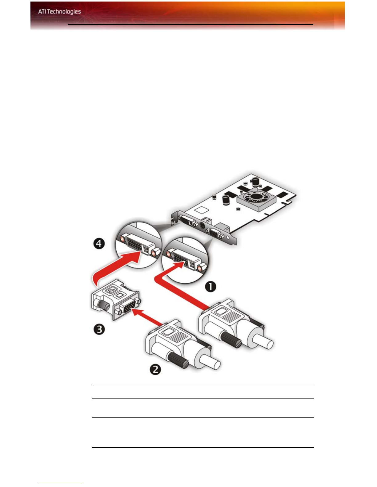
Connections and Adapters for the Radeon® X850 Series Card
X
Y
DVI Monitor Connector.
VGA Monitor Connector. To connect a VGA monitor to the DVI-I
connector, plug the supplied DVI-I-to-VGA adapter into the DVI-I
connector, then plug your monitor cable into the adapter
Page 10
4 Display Configurations
Connections and Adapters for the Radeon® X850 Series Card
Z
[
DVI-I-to-VGA Adapter.
DVI-I Backplate Connection. To connect a flat panel, plug the
monitors DVI-I connector into the DVI-I connection.
Note: If you use multiple monitors, the Radeon® X850 Series card
must be the primary graphics card. Normally, the system BIOS
determines which graphics card will be the primary.
To connect your monitors
1 Power off your computer and monitors.
2 Plug the monitor cables into their appropriate connectors.
3 Power on your monitors first, and then restart your computer so that
Windows® can detect the new hardware settings.
4 When the New Hardware Found Wizard appears, at the appropriate
prompt insert the ATI Installation CD to load the drivers for your
Radeon® X850 Series card.
Display Configurations
Your Radeon® X850 Series graphics card provides dual display
functionality and TV Out. The following table lists the different ways you
can connect displays to your card.
Display
Configuration
Single DFP
display
Single CRT
display
Single TV S-Video Out The S-Video out can also support a
Single HDTV
display
Connector(s)
Used
DVI-I connector DFP - digital flat panel display.
DVI-I connector
with DVI-I-to-VGA
adapter
S-Video Out to
HDTV (YPrPb)
cable
Comments
CRT- cathode ray tube analog
display.
composite connection via the SVideo-to-Composite adapter.
HDTV - High Definition Television
Page 11

Display Configurations 5
Display
Configuration
DFP display +
TV
CRT display +
TV
CRT display +
HDTV
DFP display +
HDTV
CRT display +
DFP display
Connector(s)
Used
DVI-I connector +
S-Video out
DVI-I-to-VGA
adapter + S-Video
Out
DVI-I-to-VGA
adapter + S-Video
Out to HDTV
(YPrPb) cable
DVI-I connector +
S-Video Out to
HDTV (YPrPb)
cable
DVI-I-to-VGA
adapter + DVI-I
connector
Comments
UNSUPPORTED CONFIGURATION
if the CRT display is attached to the
DVI-I connector via the DVI-I-to-VGA
adapter.
CRT display +
CRT display
DFP display +
DFP display +
TV
DFP display +
DFP display +
HDTV
CRT display +
DFP display +
HDTV
CRT display +
CRT display +
TV
DVI-I-to-VGA
adapter + DVI-I-toVGA adapter
DVI-I connector +
DVI-I connector +
S-Video Out
DVI-I connector +
DVI-I connector +
S-Video Out to
HDTV (YPrPb)
cable
DVI-I-to-VGA
adapter + DVI-I
connector + SVideo Out to HDTV
(YPrPb) cable
DVI-I-to-VGA
adapter + DVI-I-toVGA adapter + SVideo Out
The DVI-I connector can support a
CRT display using the DVI-I-to-VGA
adapter
The TV display will “clone” the image
of one of the other two displays
UNSUPPORTED CONFIGURATION
Page 12

6 Display Configurations
Display
Configuration
CRT display +
CRT display +
HDTV
Connector(s)
Used
DVI-I-to-VGA
adapter + DVI-I-toVGA adapter + SVideo Out to HDTV
(YPrPb) cable
Comments
UNSUPPORTED CONFIGURATION
Page 13

CHAPTER 3:
Cat alyst™ Control Center
The Catalyst™ Control Center is a graphical representation of the display
features of the installed ATI hardware and software. Use the Catalyst™
Control Center to fine-tune your graphic settings, enable or disab le
connected display devices, and change the orientation of your desktop.
Many of the features show you a preview of the changes before they are
applied.
The Catalyst™ Control Center offers you two views of the software:
Standard view is a simplified view that includes wizards to get the
inexperience user up and running. The Advance view allows the advanced
user to access and configure the complete feature set of the software.
7
The Catalyst™ Control Center can be customized for easy access to the
features you use most.
Use the Catalyst™ Control Center to access a comprehensive online help
system, or connect to the ATI Web site.
Catalyst™ Control Center can be launched from one of the following
access points:
• Windows Start Menu
• Windows System Tray
• Predefined Hotkeys
• Desktop Shortcuts
• Via an ATI MMC Application
Launching Catalyst™ Control Center Usin g the St art
Menu
From the windows task bar, click the Start button:
• For Windows XP, point to All Programs>ATI Catalyst™
Control Center .
• For Windows 2000, point to Programs>ATI Catalyst™
Control Center .
Page 14

8
Other Quick Launch Access Points
To launch Catalyst™ Control Center from MMC
You can also access the Catalyst™ Control Center while an ATI multimedia application, like TV Player, is running. Simply click the Catalyst™
Control Center icon in the multi-media application’s control panel, if
available.
Launching Catalyst™ Control Center Using Hot Keys
You can press a predefined key (like F7) or combination of keys (like
Ctrl+A). You can define your hot key by using the Hotkey Manager.
Launching Catalyst™ Control Center Using the Desktop
Shortcut
When you first installed Catalyst™ Control Center the setup wizard
provided you with the option of placing a shortcut on the desktop. If you
selected this option, simply double-click the Catalyst™ Control Center
desktop shortcut.
Launching Catalyst™ Control Center Using the System Tray
Right-click the ATI icon in the Windows® System Tray and select
Catalyst™ Control Center from the popup menu.
The Displays Manager is the central location for configuring your display
devices and arranging your desktop. Use the Displays Manager to quickly
Page 15

9
change your display setup, arrange your desktop in a multi-monitor
environment, and enable TV Out.
Displays Manager appears in both Standard and Advanced Views. Use the
Standard View wizard to help you configure your display preferences.
Experienced users who prefer to manually configure their desktop setting
should use the Advanced View.
Standard View
Advanced View
Page 16

10 Video
Use 3D to adjust features found in 3D applications, such as graphic-design,
CAD programs and games.
3D is available in the simplified standard view and advanced view. Use
standard view to adjust the overall performance and quality of your graphic
application. Use the advanced view to individually configure the following
settings:
• Standard Settings
• Anti-aliasing
• Anisotropic Filtering
• Catalyst™ A.I.
• Mipmap Deta il Level
•TruForm™
• SmartShader™
•API-Specific
Video
Use the Video aspect to use preconfigured profiles that best match your
viewing environment. Switch to the Advanced view to manually adjust
video overlay and choose a preferred viewing mode, such as Widescreen or
Fullscreen modes.
• Select Video in either Standard or Advanced View.
Display Options
The Display Options gives you additional control to optimize performance
of OpenGL® and Direct 3D® applications.
Use 3D Refresh Rate Override to set a refresh rate of your choice when a
full-screen application or game has a default refresh rate that is lower than
optimal.
Choose one of the Display Detection Options to prevent screen flicker
when detecting a display.
If you are using an older TV or one that has non-standard inputs that may
not be automatically detected, use Force TV Detection. Such a TV, once
detected, will appear in the Displays Manager aspect and can be configured
Page 17

Color 11
as required. However, some features that rely on automatic detection, such
as extended desktop, will not be supported.
• Select Display Options in the Catalyst™ Control Center
Advanced View.
Color
Use the Color aspect to adjust the color settings for your desktop and fullscreen games. The Preview effects area shows your changes to gamma,
brightness, and contrast in real time.
• Select Color in Advanced View.
GPU Recover
GPU Recover is a tool capable of detecting the rare situation when the
graphics processor is no longer able to respond to display driver
commands. When this occurs, GPU Recover attempts to reset the graphics
processor so that you are able to continue using your computer without
interruption or loss of data.
• Select GPU Recover in Advanced View.
Use the yMonitor Properties page to configure your Display Data Channel
(DDC) monitor’s attributes, to display information about the connected
monitor, and adjust the output display’s position and size.
To access Monitor Properties
• Select Monitor Properties in Advanced View.
TV Properties
If your graphics card has support for TV Out use the TV Properties to
configure your TV settings.
The TV Properties is comprised of:
• Image Quality
• Color
• Adjustments
•Formats
Page 18

12 Hotkeys Manager
Use Image Quality to adjust the contrast, saturation, and flicker of your
screen.
Use Color to adjust Hue, Saturation, and Temperature.
Note: This feature is supported by specific high-end ATI graphics
cards only.
Use Screen Adjustment to set the vide o mode, enable overscan, and change
the position and size of the screen.
Use Formats to determine how the TV signal is to be detected.
Use the Digital Panel Properties to configure the DVI settings and Image
Scaling to improve image quality without impacting performance. Use
HDTV Support to add EDID information to the Force button of the
Displays Manager.
Hotkeys Manager
The Hotkeys Manager allows you to create shortcut key combinations to
quickly perform tasks such as changing a graphics setting or opening an
application. A hot key is a combination of one or more modifier keys, such
as Ctrl, Alt, or Shift, and any letter from the alphabet.
Use ATI Overdrive 3 to maximize the performance of the graphics
processing unit (GPU) on your graphics card. An on-chip thermal sensor
constantly monitors the temperature of the GPU allowing the maximum
clock speed to be maintained while avoiding overheating. If the GPU gets
too hot, ATI Overdrive 3 will automatically decrease the clock speed until
a safe temperature is reached. ATI Overdrive 3 will never reduce the
graphics processor speed below the default clock speed.
Use the Automated clock configuration utility to obtain the ATI
recommended ATI Overdrive 3 speeds for the graphics processor clock and
video memory clock. Alternatively, manually set these speeds to meet your
specific requirements. Finally, ATI Overdrive 3 can be configured to run
when the computer is booted or only when running 3D applications.
• If your computer cannot restart after set ting a higher clock speed,
press and hold the SHIFT key during system start-up until you
hear three beeps. Once your computer has full booted, disable
Enable new clock settings at logon.
Page 19

Profiles Manager 13
Profiles Manager
Use profiles to create customized environments for your desktop, video,
and 3D applications. Define and save your own personal video settings that
can be quickly activated manually, through a hot key, or by file association.
Note: A profile applies to a specific graphics card. If there is more
than one graphics card installed in your computer, you need to select
the appropriate card before creating, loading, or activating a profile.
Preferences
Use the Preferences page to restore factory defaults, change skins, or
enable\disable the System Tray icon.
The CATALYST™ Control Center Preferences page contains the
following options:
• Hide Tooltips
•Always on Top
• Enable System Tray menu
• Restore factory defaults
• Show Toolbar Text
• Select a Language
• Select a Skin
Help
Use the Catalyst™ Control Center Help feature to access the
comprehensive online help system, generate a Problem Report, and get the
installed version information.
Page 20

14 Help
Page 21

Using TV Out 15
CHAPTER 4:
Using TV Display and Capture Features
This chapter describes how to use the TV display and video capture
features of your Radeon® X850 Series card.
Using TV Out
Your Radeon® X850 Series has TV Out capability.
Viewing Your PC’s Display on a TV
You can attach your Radeon® X850 Series to a TV and a monitor at the
same time.
L
TV display is ideal for giving presentations and watching movies, or
playing games on a screen larger than a typical monitor. The following tips
will help you get the most out of your TV Out feature.
IMPORTANT INFORMATION for European Customers
Some PC monitors in Europe cannot be used simultaneously with TV
display. When you enable TV display in Europe, the refresh rate for the
monitor and TV is set to 50 Hz. Some monitors may not support this
refresh rate and could be damaged.
• Please check the documentation supplied with your monitor to see if
your monitor supports a refresh rate of 50 Hz.
• If your monitor does not support 50 Hz (or if you are not sure), turn off
your monitor before turning on your PC when using your TV as a
display.
Connecting to a TV or VCR
To connect your Radeon® X850 Series card to a TV or VCR, use an SVideo cable. Many TVs (and VCRs) have a Composite video input, in
which case you can use the supplied S-Video-to-Composite video adapter.
If your TV has cable input only, you can connect your graphics card to your
TV through your VCR or an RF modulator that is available from most
electronics stores.
Page 22

16 Using TV Out
To connect S-Video Out
1 Power off your computer and your TV (or VCR).
2 Determine if your TV (or VCR) supports either a S-Video or
Composite video connection.
3 Looking at the back of your PC, locate your S-Video Out. Using an S-
Video cable or the supplied adapter cable, attach one end of the cable
to your graphics card and the other to your TV (or VCR). Refer to the
illustration.
4 Power on your TV (or VCR) first, then your computer.
Connecting Your S-Video Out to a TV or VCR
X
Y
Z
[
S-Video Connection on graphics card
TV or VCR
S-Video Cable (with or without S-Video-to-Composite Adapter)
Computer
Page 23

Using TV Out 17
Using a Monitor vs. Using TV Display
Using your TV for your computer’s display can be useful, however, the
display on your monitor may change or looked squashed. This distortion
occurs because the display adjusts to fit the dimensions of your TV. To
correct the monitor’s display, use the monitor’s control buttons to adjust its
display size and position.
Some single-frequency monitors may not work with TV display enabled. If
you experience problems when TV display is enabled, disable TV display
to restore your monitor’s display.
Viewing Text on a TV
A TV is designed primarily to show moving images. The large dot pitch of
a TV will yield poor quality static images. The small text sizes commonly
used for PC desktops can appear blurred or unclear on a TV. You can
compensate for this degradation by using larger fonts.
Switching to a larger display font
1 Access the Display Properties dialog by right-clicking on the desktop
or navigating through Windows®
Control Panel.
2 Click the Settings tab, the Advanced button, and then the General
tab.
3 In the Display section, select Large (120 DPI) from the Font Size
(or DPI Setting) drop-down list.
4 Click Apply. If prompted, click Yes to restart your Computer.
Using A TV As The Only Display
If you plan to move your computer to a place where you are using TV
display only, make sure that you have the TV display feature enabled prior
to removing the monitor.
The maximum display resolution for TV is 1024 x 768. Choosing a
resolution higher than this will cause the TV display to disappear if it is the
only display device.
Using Games and Applications
Some older games and applications may program your Radeon® X850
Series directly to run under a specific display mode. This may cause your
TV display to turn off automaticall y or beco me scrambled (your PC
monitor or portable LCD display will not be affected). Your TV display
will be restored once you exit the game or if you restart your computer.
Page 24

18 Connecting to HDTV
Connecting to HDTV
View computer output directly on your High Definition Television
(HDTV) or other component input device. Provide a big-screen experience
for your computer that is ideal for playing games, giving presentations,
watching movies, and browsing the Internet.
HDTV uses YPbPr connectors to receive input. YPbPr stands for the
following:
• Y = Green
• Pb = Blue
•Pr = Red
The HDTV Component Video Adapter can be used in place of the standard
A/V Output cable to connect to an HDTV or other component input device,
using component video cables.
L
You must have a monitor attached to your computer before installing
the ATI HDTV. For proper operation of your ATI Component Video
Adapter, ATI display drivers must be correctly installed.
ATI HDTV Cable
X
ATI HDTV Video Output Cable
Page 25

ATI HDTV Cable
Using Your ATI HDTV Video Cable 19
Y
Z
[
Installing your ATI HDTV video cable
Backplate of the ATI Graphics Card
Male RCA Patch Cables – available from consumer electronics dealer
Typical HDTV Video Input Connections
Note: Input and output cables lengths should not exceed 50 feet
(15m).
1 Turn on your component input device, and set it to YPbPr input.
Note: See your HDTV or component input device manual for
configuration information specific to your device.
2 Turn on your computer.
Note: Your TV will not display anything until Windows starts. This
can take several minutes.
Using Your ATI HDTV Video Cable
Use the HDTV Video Cable to watch DVD movies and play video games
on your High Definition Television.
L
For maximum performance when you watch DVD movies or play
computer games on your HDTV, you should find the mode and screen
resolution that provide the best result on your TV, and use those settings
exclusively.
Copy-protected DVDs restrict playback to 480i and 480p modes.
Capturing Video
The Radeon® X850 Series has the ability to capture video from your
camcorder, VCR, or TV. Use your favorite video editing application to add
effects, make changes, or stream your video on the Internet.
Page 26

20 Capturing Video
The audio and video output connectors on your TV, camcorder, or VCR
will be similar those depicted in the illustration. Use Composite Video Out
or S-Video Out. S-Video Out will provide better results.
Connecting Your Video Device to Your Radeon® X850 Series Card
A
B
X
Y
Z
[
Composite In and Out Connectors. Recommended connecto r
for best picture quality.
S-Video In and Out Connectors.
ATI Graphics Card
Video In/Video Out Cable
Typical Video In of TV, VCR, or Camcorder connections
Typical Video Out of TV, VCR, or Camcorder connections
Connecting your media device for video capture
Use the Video In/Video Out Cable to connect to a TV, VCR, or Camcorder.
Use the S-Video connectors.
Page 27

Capturing Video 21
To capture video to your computer
1 Connect the ATI Video In/Video Out cable to the Video In/Video Out
connector on the ATI Graphics Adapter.
2 Connect the Video In of the ATI Video In\Video Out cable to the
Video Out of your media device.
Note: S-Video and Composite extension cables are available from a
consumer electronics dealer
3 Start your video capture software in record mode. For more
information see the documentation that came with your video capture
software.
4 Power on your TV or hit Play on your TV or VCR.
Note: To capture sound, you must connect the Line Out of your
media device to the Line In of your sound card. Audio cables are
available from a consumer electronics dealer.
Setting the Windows® Volume Control
For correct audio performance, your sound card’s Line Input must be
active.
To display the Line Input settings
1 Right-click the Speaker icon in the Taskbar, which usually in the
lower-right corner of your screen.
If the volume icon is not in your Taskbar, do the following:
•Click
• Double-click
•In the
2 Click Open Volume Controls.
3 If the Line-In volume slider is not visible, click Options, then click
Properties.
4 Click the Line-In volume control checkbox, then click OK. If the
Mute checkbox is checked, click it to cancel muting.
Start, then click Control Panel.
Sounds and Audio Devices.
Volume tab, check Place volume icon in the taskbar.
Page 28

22 Capturing Video
Page 29

Uninstalling Old Graphics Card Software 23
CHAPTER 5:
T roubleshooting
The following troubleshooting tips may help if you experience problems.
ATI’s documentation contains helpful installation/configuration tips and
other valuable feature information. Please contact your dealer for more
advanced troubleshooting information.
More troubleshooting information can be found on the ATI Website at
ati.com/support/.
Uninstalling Old Graphics Card Software
To ensure successful installation of your Radeon® X850 Series card, you
must uninstall the graphic drivers for the existing graphics card before
removing it from your computer.
To uninstall old graphics drivers
1 With your current graphics card still in your computer, close all open
applications.
2Click
Programs
3 Select your current graphic drivers, then click
• The Wizard will help you remove your current display drivers.
• Restart your system after the drivers have been removed.
L
Start > Settings > Control Panel, then select Add/Remove
.
Add/Remove:
If the previously installed graphics card has any additional software
installed, they may also need to be removed at this point. For example,
DVD Player or Multimedia applications.
Windows® New Hardware Found
Windows may start the Add New Hardware Wizard to install the
Standard VGA Driver.
Page 30

24 Installing the CATALYST™ Software Suite
To install and detect your new hardware
1Click Next to allow Windows® to search for the Standard VGA or
Standard PCI Graphics Adapter.
If prompted for the Windows® CD-ROM, insert it into your CDROM drive.
2 Type the following:
D:\WinXP.
If
D is not your CD-ROM drive, substitute D with the correct drive
D:\<Operating System name> for example
letter.
3Click
4Click
OK.
Finish to close the Wizard and then restart your system.
Installing the CATALYST™ Software
Suite
ATI’s CATALYST™ software suite provides you with all you need to get
the most out of your ATI Graphics Accelerator card. To ensure you install
supported software, use the ATI Installation CD-ROM that shipped with
your ATI Graphics Accelerator card.
To install the CATALYST™ Software Suite
1 Insert the ATI INSTALLATION CD-ROM into your CD-ROM
drive.
If Windows® runs the CD-ROM automatically, proceed to step 6.
2Click
3 Select
Start.
Run.
4 Type the following:
If D is not your CD-ROM drive, substitute D with the correct drive
letter.
5Click
6Click
7Click
8Click
9Click
OK.
Install under Software Install.
Next.
Yes to the license agreement.
ATI Easy Install to begin the Installation Wizard.
10 Follow the Wizard’s on-screen instructions to complete the
installation.
D:\ATISETUP
Page 31

Solution Selector 25
Note: The Express installation option is recommended. If your ATI
Graphics Accelerator card includes a multimedia component, the
software for that component will automatically be installed, along
with the ATI graphics driver. Not all software components are
installed using the Express installation. Custom installation allows
you to select individual software components for installatio n.
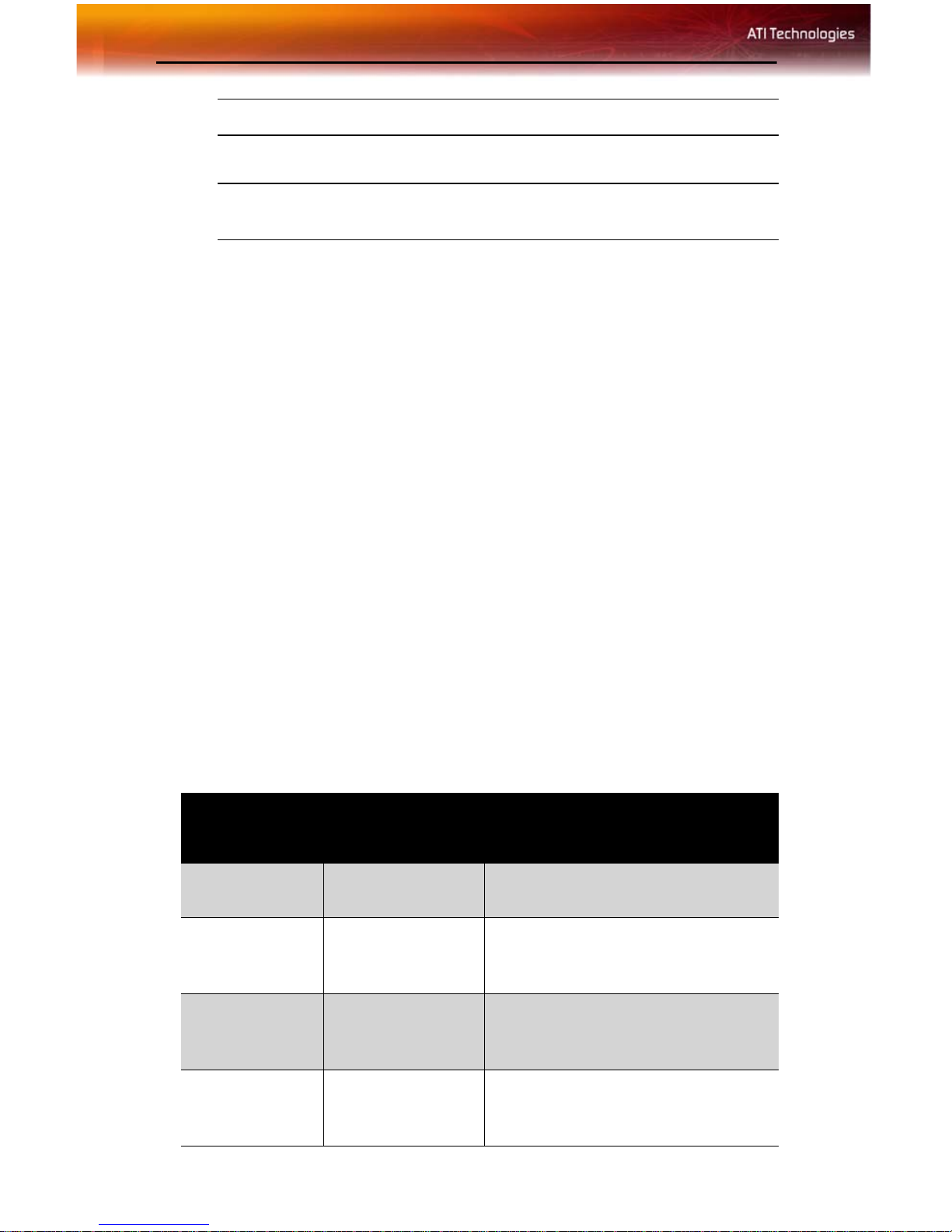
Solution Selector
General Problems
Problem Possible Solution
Computer Does
Not Boot-Up
Properly
No Display • Check that the card is seated properly in its expansion
• Verify that the installation instructions were properly
followed.
• Check that the card is properly installed in your system
and connected to your monitor.
• If you have problems during start-up, restart your
computer in Safe Mode.
While started Windows® 2000 and Windows® XP
press and hold F8 until you see the Windows®
Advanced Options Menu. Use the arrow keys to select
Safe Mode, and press Enter.
• Check the system configuration utility of your operating
system for the interrupt assignments.
• Contact ATI’s Customer Care or your local technical
support.
slot.
• Ensure that the monitor cable is securely fastened to
the card.
• Make sure that the monitor and computer are plugged
in and receiving power.
• If necessary, disable any built-in graphics capabilities
on your mother board. For more information, consult
your computer’s manual or manufacturer. (Note: some
manufacturers do not allow the built-in graphics to be
disabled or to become the secondary display.)
• Make sure that you selected the appropriate monitor
when you installed your enhanced driver.
Page 32

26 Solution Selector
General Problems
Problem Possible Solution
Screen Defects
Appear
Off-Center
Screen Image,
Odd Colors or No
Picture
• Check if your monitor supports the resolution,
horizontal (kHz) and vertical (Hz) refresh rates as
required by the graphics card.
• Check your current resolution, refresh rate, and color
depth settings in the Settings and Monitor tabs in your
Display Properties dialog.
Warning! Ensure that both video card and monitor
support resolution and refresh rates you select.
Incompatible resolution/refresh rate selection may result in
monitor damage. Refer to your monitor's documentation
for recommended resolutions and refresh rates.
• Try adjusting the brightness, sharpness, contrast, and
color balance controls of your monitor.
• Try adjusting the centering and positioning controls of
your monitor to position the picture on the screen.
• Set the monitor's RGB inputs (and sync switches, if this
option is available) to 75 Ohms, with the sync set to
external.
• Digital Flat Panel (DFP) monitor users: refer to your
monitor's documentation for the appropriate cable and
connector to plug into the DVI-I connector on the
graphics card.
Operating
System Warns
that Video Card
Isn’t Properly
Configured
• Check the driver installation and make sure that all
software is correctly loaded corresponding to your
operating system and applications.
• Re-install the ATI drivers for your Radeon® X850
Series card.
HDTV/HDTV Adapter Troubleshooting
Problem Possible Solution
The colors on my
TV display are
incorrect
There is no
display on my TV
• Ensure that the connections between the Component
Video Adapter and your HDTV are correct (Y=Green,
Pb=Blue, Pr=Red).
• Your TV will not display anything until Windows starts;
this may take several minutes.
• Set your TV to YPbPr input.
• Ensure that the HDTV Component Video Adapter is
properly connected, then restart your computer.
Page 33

HDTV/HDTV Adapter Troubleshooting
Problem Possible Solution
Solution Selector 27
DVDs will not
play in 720p or
1080i modes
I can’t see the
entire display
The display
appears tilted
My CRT display is
green
• Copy-protected DVDs restrict playback to 480i and
480p modes.
• If your component input device supports it, try 720p
mode.
• Consult your HDTV user’s manual.
• Your system is in component output mode. Restart
your computer with the CRT monitor connected.
Page 34

28 Solution Selector
Page 35

Index
Numerics
3D Settings
A
Adjustments
ATI Overdrive ™ 3 12
C
capture video
CATALYST Software
installing 24
Color 11
Copy-protection
DVDs, DVDs
D
Dashboard
Digital Panel properties 12
Display Options 10
Displaying PC output on TV 19
dot pitch 17
E
external connectors
F
Formats
G
games
TV display 17
H
HDTV
HDTV adapter
HDTV Component Video Adapter 18
Help 13
High Definition Television 18
Hotkeys Manager 12
I
Image Quality
Input and output adapters
installing
18, 19
troubleshooting 26
troubleshooting 26
displaying PC output on TV and recording on videotape 19
CATALYST Software 24
10
11
19, 21
Copy-protection 27
7
1
11
11
29
Page 36

30
O
old graphics drivers
uninstall 23
P
Preferences
Profiles 13
R
Recording PC output on videotape
S
safety instructions
system requirements 1
T
troubleshooting
general problems 25
HDTV 26
HDTV adapter 26
TV
displaying PC output on 19
TV display 15, 17
games 17
TV Out 15
TV Properties 11
U
uninstall
old graphics drivers 23
Uninstalling old graphics card software 23
V
Video
video capture 19
Volume control 21
W
Windows volume control
Y
YPbPr
YPbPr connector 18
10
26
13
19
iii
21
 Loading...