

Page 1

Radeon® X1900
Series
User’s Guide
P/N 137-40973-10
Page 2

ii
Copyright © 2005, ATI Technologies Inc. All rights reserved.
ATI, the ATI logo, and ATI product and product-feature names are trademarks and/or registered
trademarks of ATI Technologies Inc. All other company and/or product names are trademarks and/or
registered trademarks of their respective owners. Features, performanc e and specificatio ns are subject
to change without notice. Product may not be exactly as shown in diagrams.
Reproduction of this manual, or parts thereof, in any form, without the expre ss written permission of ATI
Technologies Inc. is strictly prohibited.
Disclaimer
While every precaution has been taken in the preparation of this document, ATI Technologies Inc.
assumes no liability with respect to the operation or use of ATI hardware, software or other products
and documentation described herein, for any act or omission of ATI concerning such products o r this
documentation, for any interruption of service, loss or interruption of business, loss of anticipatory
profits, or for punitive, incidental or consequential damages in connectio n with the furnishing,
performance, or use of the ATI hardware, software, or other products and documentation provided
herein.
ATI Technologies Inc. reserves the right to make changes without further notice to a product or system
described herein to improve reliability, function or design. With respect to ATI products which this
document relates, ATI disclaims all express or implied warranties regarding such products, including
but not limited to, the implied warranties of merchantability, fitness for a particular purpose, and noninfringement.
Macrovision
Apparatus Claims of U.S. Patent Nos. 4,631,603, 4,577,216, 4,819,098 , and 4,907,093 licensed for
limited viewing uses only.
This product incorporates copyright protection techno lo gy tha t is protected by method claims of certain
U.S. patents and other intellectual property rights owned by Macrovision Corporation and other rights
owners. Use of this copyright protection technology must be authorized by Mac rovision Corporation,
and is intended for home and other limited viewing uses only unless otherwise authorized by
Macrovision Corporation. Reverse engineering or disassembly is prohibited.
Page 3

IMPORTANT SAFETY INSTRUCTIONS
L
• Read Instructions - All the safety and operating instructions should
be read before the product is operated.
• Retain Instructions - The safety and operating instructions should be
retained for future reference.
• Heed Warnings - All warnings on the product and the operating
instructions should be adhered to.
• Compatibility - This option card is for use only with IBM AT or
compatible UL Listed personal computers that have Installation
Instructions detailing user installation of card cage accessories.
• Grounding - For continued protection against risk of electric shock
and fire, this accessory should be installed only in products equipped
with a three-wire grounding plug, a plug having a third (grounding) pin.
This plug will only fit into a grounding-type power outlet. This is a
safety feature. If you are unable to insert the plug into the outlet,
contact your electrician to replace the obsolete outlet. Do not defeat
the safety purpose of the grounding-type plug.
• Secure Attachment
tightened as to provide continuous bonding between the option card
and the PC chassis.
• Lightning - For added protection for this product during a lightning
storm, or when it is left unattended and unused for long periods of
time, unplug it from the wall outlet, and disconnect the antenna or
cable system. This will prevent damage to the product due to lightning
and power-line surges.
• Power Lines - An outside antenna system should not be located in
the vicinity of overhead power lines or other light or power circuits, or
where it can fall into such power lines or circuits.
• Antenna Installation - When installing an outside antenna system,
extreme care should be taken to keep from touching such power lines
or circuits, as contact with them may be fatal.
- All card securement pins shall be completely
iii
Page 4

iv
Page 5

Table of Contents
Introduction . . . . . . . . . . . . . . . . . . . . . . . . . . . . . . . 1
Radeon® X1900 Series Features 1
Graphic Features 1
System Requirements 4
External Connectors 4
Before You Begin 5
Record Your Serial and Part Numbers 5
Uninstall Previous Graphics Card Drivers 5
Installing Hardware . . . . . . . . . . . . . . . . . . . . . . . . . 7
Graphics Card Bus Types 7
Basic Graphics Card Installation 7
Advanced Installation: AGP 9
Advanced Installation: PCIe™ 11
Connecting Devices 13
v
Using Multiple Displays . . . . . . . . . . . . . . . . . . . . 15
Connecting Your Monitors 15
Display Configurations 17
Installing Software and Drivers . . . . . . . . . . . . . . 19
Installing Drivers and Software in Windows® 19
Software Installation Prerequisites 19
Monitor Configuration 20
Reinstalling Drivers 21
Installing the Catalyst™ Software Suite 22
Catalyst™ Control Center . . . . . . . . . . . . . . . . . . 25
Launching Catalyst™ Control Center 25
Launching Catalyst™ Control Center Using the Start Menu 25
Page 6

vi
Other Quick Launch Access Points 26
Catalyst™ Control Center Dashboard 28
Create a Custom View 29
Hotkeys Manager 29
Profiles Manager 31
Preferences 33
Help 35
Information Center 36
Displays Manager 38
Displays Manager Advanced View 39
Display Options 43
Monitor Properties 46
Monitor Attributes 47
Digital Panel Properties 48
Attributes 49
Avivo™ Color 51
HDTV Support 52
3D 55
Standard Settings 56
Anti-aliasing 57
Set the Anti-Aliasing preference manually 58
Adaptive Anti-aliasing 59
Anisotropic Filtering 60
Catalyst™ A.I. 62
Mipmap Detail Level 63
All Settings 65
Set the Anti-Aliasing preference manually 66
API Specific 68
Color 70
Color Desktop 71
Color - FullScreen 3D 74
Avivo™ Video for Radeon® Series starting from 9500 75
Standard Settings 76
Adjustments 77
Video Overlay Theater Mode 79
Deinterlacing 80
VPU Recover 85
CrossFire™ 87
Using TV Display and Capture Features . . . . . . . 95
Using TV Out 95
Viewing Your PC’s Display on a TV 95
Connecting to a TV 95
Using a Monitor vs. Using TV Display 96
Page 7

Viewing Text on a TV 97
Using a TV as the Only Display 97
Using Games and Applications 97
Connecting to HDTV 97
Using Your ATI HDTV Video Cable 99
CrossFire™ FAQ . . . . . . . . . . . . . . . . . . . . . . . . . 101
Using the Radeon® X1900 Series with CrossFire™
105
CrossFire™ Overview 105
Allowable CrossFire™ System Components 105
CrossFire™ Rendering Modes 105
SuperTiling 106
Scissor Mode 107
Alternate Frame Rendering (AFR) Mode 108
Super Anti-aliasing Mode 109
Reference . . . . . . . . . . . . . . . . . . . . . . . . . . . . . . . 113
Troubleshooting 113
Product Registration 117
Customer Care 117
Getting Additional Accessories 119
Compliance Information 119
FCC Compliance Information 119
Industry Canada Compliance Statement 120
Waste Electrical and Electronic Equipment
(WEEE) Directive Compliance 120
vii
Glossary . . . . . . . . . . . . . . . . . . . . . . . . . . . . . . . . 121
Page 8

viii
Page 9

Radeon® X1900 Series Features 1
CHAPTER 1:
Introduction
Congratulations on the purchase of your ATI Radeon® X1900 Series
graphics card. We hope that you will enjoy countless hours of trouble-free
computing.
Radeon® X1900 Series Features
Graphic Features
• Native PCI Express® X16 bus support.
• 256MB or 512 MB GDDR3 on-board memory.
• Full support for Microsoft® DirectX® Shader Model 3.x.
• High performance Ultra-Threaded shader engine.
• Eight vertex shader processors.
• Forty-eight pixel shader processors.
• 512-bit internal ring-bus memory controller.
• 256-bit 8-channel memory interface.
• Native PCI Express® x16 bus interface.
SmoothVision™
• Full-scene anti-aliasing method that smooths uneven edges and
improves blurred images.
• 2x/4x/6x Anti-aliasing modes with a loss-less compression up to a
ratio of 6:1 at all resolutions.
• 2x/4x//8x/16x Anisotropic Filtering modes with up to 128-tap
texture filtering.
HyperZ™
• Ensures optimal hardware performance by discarding irrelevant
object data that is not visible to the user.
• Conserves video memory bandwidth.
• Loss-less Z-buffer compression
Page 10

2 Radeon® X1900 Series Features
• Z Cache optimized for real-time shadow rendering.
VideoShader™
• Seamlessly integrates pixel shaders with video in real time.
• All format DTV/HDTV decoding.
• Adaptive Per-Pixel- De-interlacing and Frame Rate Conversion.
512-bit Ring Bus Memory Controller
• Programmable intelligent arbitration logic.
• New fully associative texture, color, and Z/stencil cache designs.
• Hierarchal Z-buffer with Early Z test.
• Lossless Z Compression (up to 48.1)
• Fast Z-Buffer Clear.
• Z Cache optimized for real-time shadow rendering.
• Optimized for performance at high display resolutions, including
widescreen HDTV resolutions.
Ultra-Threaded Shader Engine
• Support for Microsoft® DirectX® 9.0 Shader Model 3.0
programmable vertex and pixel shaders in hardware.
• Full speed 128-bit floating point processing.
• Up to 512 simultaneous pixel threads.
• Dedicated branch execution units for high performance dynamic
branching and flow control.
• Dedicated texture address units for improved efficiency.
• High resolution texture support (up to 4k x 4k).
• Up to 1,536 instructions per rendering pass.
• 3Dc+ texture compression
• High quality 4:1 compression for normal maps and luminance
maps.
• Works with any single-channel or two-channel data format.
• Multiple Render Target (MRT) support.
• Render-to-vertex buffer support.
• Complete feature set also supported in OpenGL® 2.0
Page 11

Radeon® X1900 Series Features 3
High Dynamic Range (HDR) Rendering
• 64-bit floating point HDR supported throughout the pipeline
• Includes support for blending and multi-sample anti-aliasing.
• High precision 10:10:10:2 integer format support.
• Includes support for blending and multi-sample anti-aliasing.
• 2x/4x/6x Anti-Aliasing modes
• Sparse multi-sample algorithm with gamma correction,
programmable sample patterns, and centroid sampling.
• New Adaptive Anti-Aliasing modes.
• Temporal Anti-Aliasing mode.
• Lossless Color Compression (up to 6:1) at all resolutions,
including widescreen HDTV resolutions.
• 2x/4x/8x/16x Anisotropic Filtering modes
• Up to 128-tap texture filtering.
• Adaptive algorithm with performance and quality options.
Page 12

4 Radeon® X1900 Series Features
System Requirements
Hardware • Intel® Pentium® 4 or AMD Athlon®.
• 512MB of system memory; 1GB or more for best
performance.
• Optical drive for installation software (CD-ROM or
DVD-ROM drive).
• Specialized PCI Express® 450 watt or greater power
supply recommended. Consult your computer system
manual to ensure the power supply is designed to
accommodate a high-end graphics card with a peak
dissipation above 75 watts.
Operating
System
Monitor • High-resolution MultiSync or multi-frequency monitors
CrossFire™
Compatibility
• Windows® XP with Service Pack 2 (SP2).
• Windows® XP Professional x64 Edition.
• Windows® 2000.
•Windows® Vista.
or any other type of VGA monitor.
• Digital flat-panel (DFP) displays or digital CRT display.
If you are planning on using this graphics card as part of a
CrossFire™ system, the following is required:
• A CrossFire™ certified motherboard with two (2) PCI
Express® X16 slots and correct PCIe™ chipset driver.
(See
ati.com/crossfire for a list of CrossFire™
certified motherboards.)
• a CrossFire™ Edition graphics card from the same
product series that works as the Master graphics card.
More information on the requirements for each of these
components can be found within the CrossFire™ FAQ.
External Connectors
• Dual DVI-I output.
• S-Video output or Video In/Video Out (VIVO) connection.
Page 13

Before You Begin 5
Before You Begin
Before you begin installing your new graphics card, please do the
following.
Record Your Serial and Part Numbers
The serial number and 102 part number printed on the graphics card are
required for registration. They are located on a sticker on the back of the
card.
X
Y
Write the numbers, shown in bold above, down before installing your new
ATI product.
Serial number (S/N)
102 part number (P/N)
Uninstall Previous Graphics Card Drivers
To ensure the successful installation of your new Radeon® X1900 Series
card, you must uninstall the drivers for the existing graphics card before
removing it from your computer.
To uninstall previous drivers
With your current graphics card still in your computer:
1 Close all applications that are currently running.
2 Navigate to the Control Panel and select Add/Remove Programs.
3 Select your current graphics card drivers and select Add/Remove.
The wizard will help you remove your current display drivers.
Note: If the previously installed graphics card has any additional
software installed, it should also be removed at this point.
Page 14

6 Before You Begin
4 Restart your system after the drivers have been removed.
Page 15

Graphics Card Bus Types 7
CHAPTER 2:
Installing Hardware
This chapter will guide you through the physical installation of your new
Radeon® graphics card.
Graphics Card Bus Types
There are three possible card bus types. See the illustration below to
determine if you have an AGP, PCI, or PCI Express® (PCIe™) graphics
card.
AGP, PCI, and PCIe™ Graphics Cards
Bus Types
AGP card and AGP expansion slot
1
PCI card and PCI expansion slot
2
PCIe™ card and PCIe™ expansion slot
3
Basic Graphics Card Installation
There are two types of installation. If your Radeon® graphics card does not
require a separate connection to the computer’s power supply, foll ow th e
Basic Install instructions below. If your graphics card requires a separate
connection to the computer’s power supply, follow the Advanced Install
instructions for either AGP or PCIe, as appropriate.
Page 16

8 Basic Graphics Card Installation
Radeon® graphics cards that require a connection to the computer’s power
supply will have a power cable connected to them.
Installing the Radeon® graphics card
1 Turn off the computer, monitor, and other peripheral devices.
2 Unplug the computer’s power cord and disconnect all cables from the
back of your computer.
L
WARNING - Wait approximately 20 seconds after unplugging the
power cord before disconnecting a peripheral or removing a
component from the motherboard to avoid possible damage to the
motherboard.
3 Remove the computer cover.
If necessary, consult your computer’s manual for help in removing
the cover.
L
WARNING - Remember to discharge your body’s static electricity by
touching the power supply or the metal surface of the computer
chassis.
4 Unscrew or unfasten and remove any existing graphics card from
your computer.
Note: If your computer has an on-board graphics capability, you may
need to disable it on the motherboard. For more information, see your
computer documentation.
5 Locate the appropriate slot and, if necessary, remove the metal back-
plate cover.
6 Align your ATI graphics card with the slot and press it in firmly until
the card is fully seated.
7 Screw in or fasten the graphics card securely and replace the
computer cover.
8 Reconnect any cables you have disconnected and plug in the
computer’s power cord.
9 Turn on the monitor and then your computer.
Page 17
Advanced Installation: AGP 9
Advanced Installation: AGP
There are two types of installation. If your graphics card does not require a
separate connection to the computer’s power supply, follo w th e
Install
instructions. If your graphics card require a separate connection to
the computer’s power supply, follow the
Advanced Install instructions
for either AGP or PCIe™, as appropriate.
Graphics cards that require connection to the computer’s power supply will
have a power cable connected in the upper-right corner of the card.
Consult your system builder or OEM to ensure that your system has an
L
adequate power supply. Generally, ATI recommends a 300 watt power
supply or greater to ensure normal system operation where a number of
other internal devices are installed.
Basic
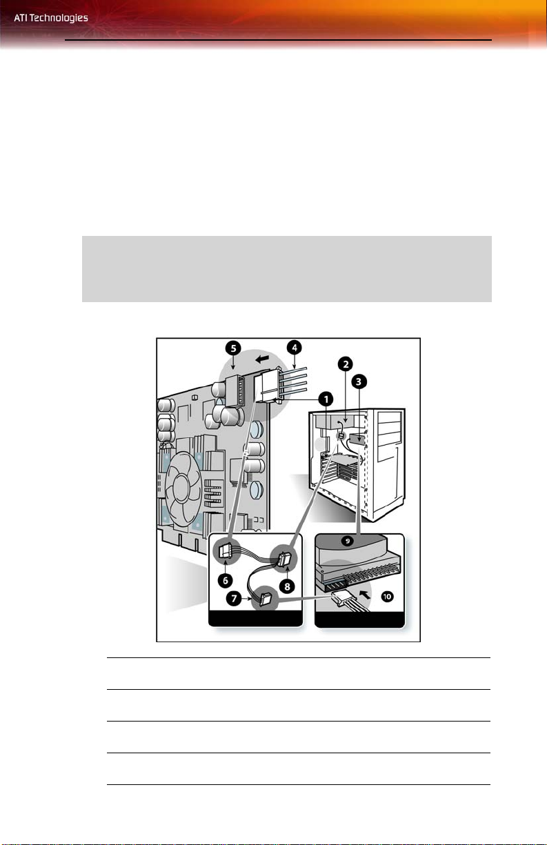
Graphic Card Installation
1
2
3
Radeon® Graphics Card
Power Supply
Hard Drive
Page 18

10 Advanced Installation: AGP
4
5
6
7
8
9
10
Power Cable Connector
4-Pin Power Connection
Power Extension Cable: Power Connector to Graphics Card
Power Extension Cable: Power Connector to Hard Drive
Power Extension Cable: Power Connector to Power Supply
Hard Drive
Power Connector to Hard Drive
Installing the Radeon® graphics card
1 Turn off the computer, monitor, and other peripheral devices.
2 Unplug the computer’s power cord and disconnect all cables from the
back of your computer.
L
WARNING - Wait approximately 20 seconds after unplugging the
power cord before disconnecting a peripheral or removing a
component from the motherboard to avoid possible damage to the
motherboard.
3 Remove the computer cover.
If necessary, consult your computer’s manual for help in removing
the cover.
L
WARNING - Remember to discharge your body’s static electricity by
touching the power supply or the metal surface of the computer
chassis.
4 Unscrew or unfasten and remove any existing graphics card from
your computer.
Note: If your computer has an on-board graphics capability, you may
need to disable it on the motherboard. For more information, see your
computer documentation.
5 Locate the appropriate slot and, if necessary, remove the metal back-
plate cover.
Page 19

Advanced Installation: PCIe™ 11
6 Align your ATI graphics card with the slot and press it in firmly until
the card is fully seated.
7 Remove the power cable from the hard drive power connector.
8 Connect the power extension cable to the 4-pin power connection on
the graphics card.
9 Connect the power extension cable to the power supply.
10 Connect the power extension cable to the hard drive.
11 Screw in or fasten the graphics card securely. Make sure the cables
are not interfering with anything inside the computer (for example, a
cooling fan) and replace the computer cover.
12 Reconnect any cables you have disconnected and plug in the
computer’s power cord.
13 Turn on the monitor, and then your computer.
Your computer will beep, possibly show a warning message on your
L
display, and the boot process will stop if the graphics card is not correctly
connected to the power supply.
Advanced Installation: PCIe™
There are two types of installation. If your Radeon® graphics card does not
require a separate connection to the computer’s power supply, foll ow th e
B
asic Install instructions. If your graphics card require a separate
connection to the computer’s power supply, follow the
instructions for either AGP or PCIe™, as appropriate.
Radeon® graphics cards that require connection to the computer’s power
supply will have a power cable connected to them.
Consult your system builder or OEM to ensure that your system has an
L
adequate power supply. A PCI Express® compatible system has a
specialized 12V graphics card power connector. A 450 watt or greater
power supply is recommended. Consult your computer system manual to
ensure the power supply is designed to accommodate a high-end
graphics card with a peak dissipation above 75 watts.
Advanced Install
Page 20
12 Advanced Installation: PCIe™
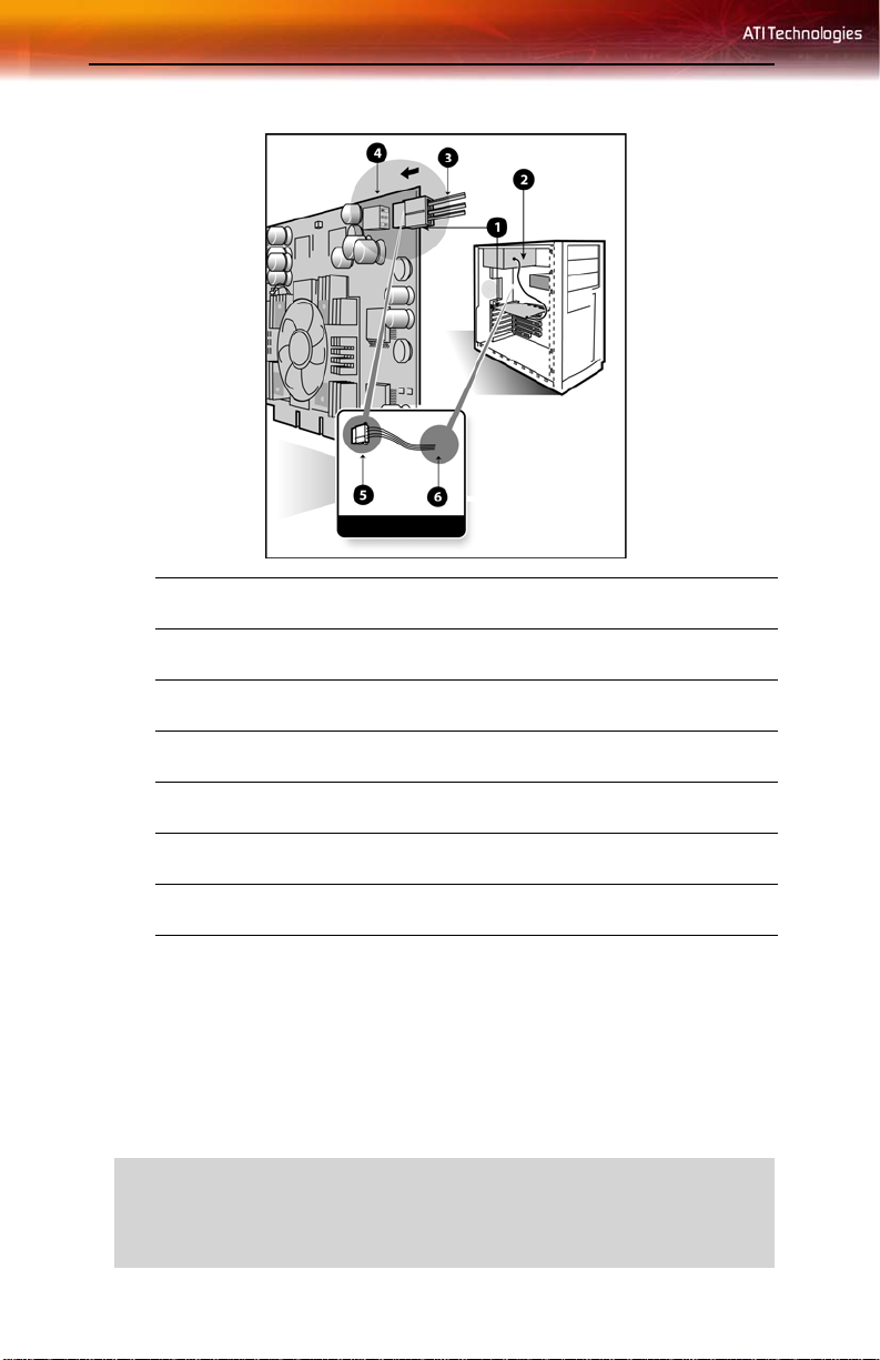
Graphics Card Installation
1
2
3
4
5
6
Radeon® Graphics Card
Power Supply
6-pin Power Cable Connector
6-pin Power Connection
Power connector to Graphics Card
Power connector to Power Supply
Installing the Radeon® graphics card
1 Turn off the computer, monitor, and other peripheral devices.
2 Unplug the computer’s power cord and disconnect all cables from the
back of your computer.
L
WARNING - Wait approximately 20 seconds after unplugging the
power cord before disconnecting a peripheral or removing a
component from the motherboard to avoid possible damage to the
motherboard.
Page 21

Connecting Devices 13
3 Remove the computer cover.
If necessary, consult your computer’s manual for help in removing
the cover.
L
WARNING - Remember to discharge your body’s static electricity by
touching the power supply or the metal surface of the computer
chassis.
4 Unscrew or unfasten and remove any existing graphics card from
your computer.
Note: If your computer has an on-board graphics capability, you may
need to disable it on the motherboard. For more information, see your
computer documentation.
5 Locate the appropriate slot and, if necessary, remove the metal back-
plate cover.
6 Align your ATI graphics card with the slot and press it in firmly until
the card is fully seated.
7 Screw in or fasten the graphics card securely. Make sure the cables
are not interfering with anything inside the computer (for example, a
cooling fan) and replace the computer cover.
8 Reconnect any cables you have disconnected and plug in the
computer’s power cord.
9 Turn on the monitor, and then your computer.
Your computer will beep, possibly show a warning message on your
L
display, and the boot process will stop if the graphics card is not correctly
connected to the power supply.
Connecting Devices
The following illustration shows typical connections found on ATI
graphics cards:
Page 22

14 Connecting Devices
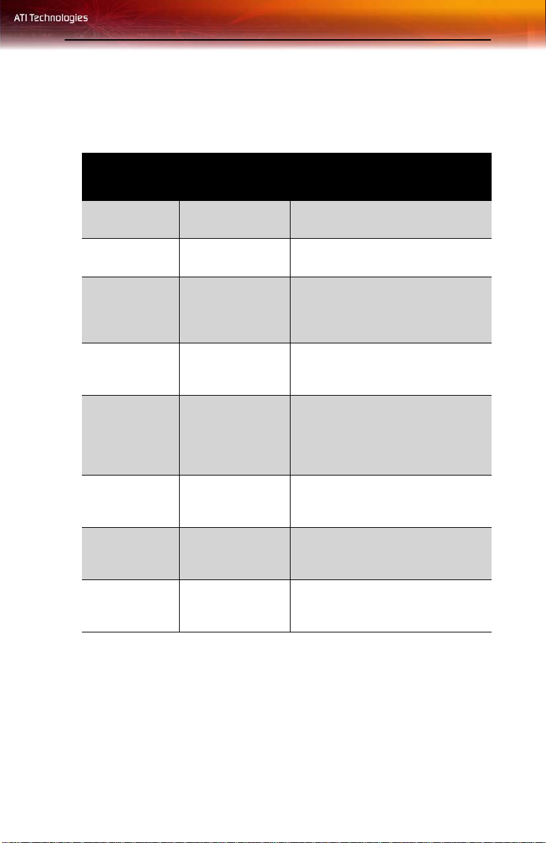
Connector Types
VGA Supports an analog CRT monitor.
DVI-I Supports a digital monitor.
VGA-DVI-I Adapter Supports an analog monitor on a DVI-I connection.
S-Video In/Out Supports a TV, VCR, or Camcorder.
CATV Supports a TV antenna or cable service.
Composite Supports a TV, VCR, or Camcorder.
L
For more information about connecting to your All-in-Wonder®
graphics card, see the AIW All-in-Wonder® Quick-Start Guide and
the All-in-Wonder® User’s Guide located on the CD that came with
your new All-in-Wonder® graphics card.
Page 23
CHAPTER 3:
Using Multiple Displays
Connecting Your Monitors
Your Radeon® X1900 Series graphics card provides hardware support for
two DVI-I monitors a DVI-I monitor and a VGA monitor using the
supplied DVI-I-to-VGA adapter. It also provides TV output via an S-Video
Out connector.
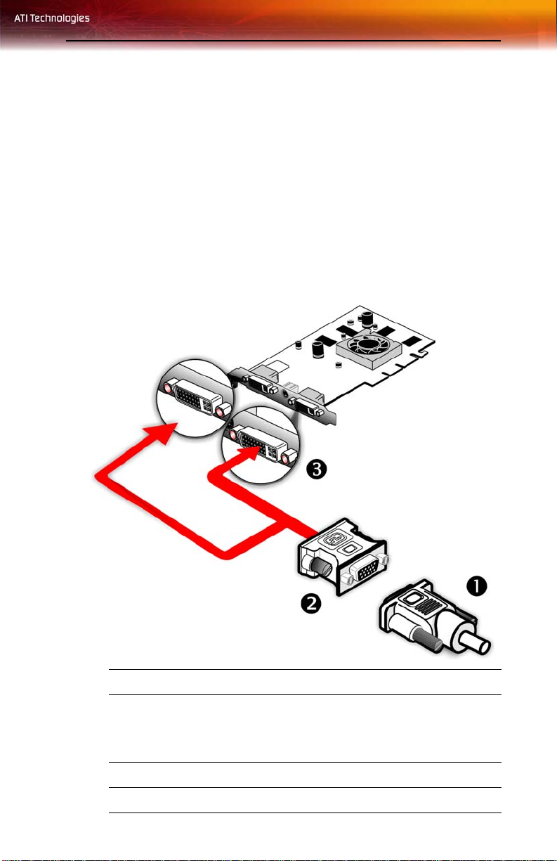
15
Connections and Adapters for the Radeon® X1900 Series Card
1 Standard VGA Monitor Connector. To connect a VGA monitor
2 DVI-I-to-VGA Adapter.
3 DVI-I Connection. To connect a digital display.
to the DVI-I connector, plug the supplied DVI-I-to-VGA adapter
into the DVI-I connector, then plug your monitor cable into the
adapter.
Page 24

16
Note: If you use multiple monitors, the Radeon® X1900 Series card
must be the primary graphics card. Normally, the system BIOS
determines which graphics card will be the primary.
To connect your monitors
1 Power off your computer and monitors.
2 Plug the monitor cables into their appropriate connectors.
3 Power on your monitors first, and then restart your comp uter so that
Windows® can detect the new hardware settings.
4 When the New Hardware Found Wizard appears, at the appropriate
prompt insert the ATI Installation CD to load the drivers for your
Radeon® X1900 Series card.
To set up a multi-monitor display
1 From the Start button click Control Panel, then Display. Click the
Settings tab to access the basic multi-monitor configuration settings.
Note: ATI provides Catalyst™ Control Center software that
provides many additional configuration features. It can be accessed
by clicking the Advanced button from the Display Properties >
Settings tab.
2 Select the Monitor icon identified by the number 2.
3 Click Extend my Windows desktop onto this monitor.
4 Set the Screen Resolution and Color Quality as appropriate for the
second monitor. Click Apply or OK to apply these new values.
• Refer to your Windows® online help and documentation for
further information on using the Settings tab.
Note: When you use multiple monitors with your card, one monitor
will always be Primary. Any additional monitors will be designated
as Secondary.
Page 25
Display Configurations 17
Display Configurations
Your Radeon® X1900 Series graphics card provides dual display
functionality. The following table lists the different ways you can connect
displays to your card.
Display
Configuration
Single DFP
display
DFP Display* +
DFP Display
DFP Display +
HDTV
Single CRT
display
CRT display +
HDTV
DFP display +
HDTV
CRT display +
DFP display
Connector(s)
Comments
Used
DVI-I connector DFP - digital flat panel display.
DVI-I connectors
DVI-I connector +
S-Video-toComponent
adapter
DVI-I connector
with DVI-I-to-VGA
adapter
DVI-I-to-VGA
adapter +
Componet Adapter
to HDTV (YPbPr)
cable
DVI-I connector +
HDTV cable
(YPbPr)
DVI-I-to-VGA
adapter + DVI-I
connector
Using supplied S-Video to
Component adapter.
CRT - cathode ray tube analog
display.
HDTV (YPrPb) adpater
CRT display +
CRT display
DVI-I-to-VGA
adapter + DVI-I-toVGA adapter
The DVI-I connector can support a
CRT display using the DVI-I-to-VGA
adapter
Note: * Both DVI ports support dual-link DVI output compatible
with single-link DVI flat panel displays as well as ultra-high
resolution dual-link DVI flat panel displays.
Page 26

18 Display Configurations
Page 27

Installing Drivers and Software in Windows® 19
CHAPTER 4:
Installing Sof tware and Drivers
This chapter will guide you through the installation of the drivers and
software associated with your Radeon® X1900 Series graphics card.
Installing Drivers and Software in
Windows®
You will need to install the Radeon® X1900 Series drivers and software in
the following cases:
• After you have installed the card in your system.
• After you have reinstalled or upgraded your operating system.
This procedure applies to Windows® XP.
Software Installation Prerequisites
To install or remove the drivers, you must have administrator rights or be
logged on as a user with administrator rights.
Your operating system must be installed and running before you can install
the Radeon® X1900 Series drivers. Also, make sure that you have installed
Service Pack 2 for Windows® XP.
Make sure your monitor cable is properly attached before you begin.
Note: The installation dialog will display in English if your operating
system’s language is not supported.
To install ATI drivers and software
Note: Optical drive refers to CD-ROM or DVD-ROM drive.
1 Start your system. When the Found New Hardware Wizard
appears, click Cancel. When the System Settings Change window
asks you to restart your computer, click No.
Page 28

20 Monitor Configuration
2 Run the ATISETUP utility. The ATISETUP utility will start
automatically when you insert the ATI Installation CD-ROM into
your optical drive after the operating system has started. If your CDROM auto-run is not enabled or the ATISETUP utility does not start
automatically:
a) Click the Start button in the task bar.
b) Click Run.
c) Select ATISETUP.EXE from the root directory of the ATI
Installation CD-ROM.
d) Click OK.
3 Click Install under Software Install.
4 Click Next.
5 Click Yes to the license agreement. ATI Easy Install will start the
Installation Wizard.
6 Follow the wizard’s on-screen instructions to complete the
installation.
L
The Express installation option is recommended. By selecting this
option, the HydraVision™ multi-monitor and desktop management
software will automatically be installed, along with the ATI driver. Not
all software components are installed using the Express installation.
Custom installation allows you to select individual software
components for installation.
7 When the Setup Complete message appears, select Yes, I want to
restart my computer now and click Finish.
8 After the system reboots, the Found New Hardware message
displays Digital Signature Not Found. Click Yes or Continue to
complete the driver installation.
Monitor Configuration
Once the drivers and software have been installed, you can configure your
monitor..
L
Warning - Choosing a refresh rate unsupported by your monitor may
damage your monitor. Consult your monitor’s documentation if
necessary.
Page 29

Reinstalling Drivers 21
To configure your primary display
1 Navigate to the Control Panel and choose Display, or right-click on
the desktop and choose Properties.
2 Choose the Settings tab and select the screen resolution and color
depth that best suit your requirements and your monitor’s
performance.
3 Click Advanced and select the Monitor tab.
4 Choose a refresh rate from the drop-down list.
5 Click OK to return to the desktop.
To set up a multi-monitor display
1 From the Start menu click Control Panel, then Display. Click the
Settings tab to access the basic multi-monitor configuration settings.
2 Select the Monitor icon identified by the number 2.
3 Click Extend my Windows desktop onto this monitor.
4 Set the Screen Resolution and Color Quality as appropriate for the
second monitor. Click Apply or OK to apply these new values.
• Refer to your Windows® online help and documentation for
further information on using the Settings tab.
Note: When you use multiple monitors with your Radeon® X1900
Series card, one monitor will always be Primary. Any additional
monitors will be designated as Secondary.
Note: You can also enable multiple monitors using ATI’s Catalyst™
Control Center.
Reinstalling Drivers
You can install new drivers or reinstall existing drivers if there was a
Windows® conflict.
Reinstall the drivers at any time using the ATISETUP utility located on the
ATI Installation CD-ROM. The ATISETUP utility will start automatically
if you insert the ATI Installation CD-ROM into your optical drive after the
operating system has started.
To manually reinstall drivers
Page 30

22 Installing the Catalyst™ Software Suite
If your CD-ROM auto-run is not enabled and the ATISETUP utility does
not start automatically, follow these steps.
1 In the Windows® task bar, click Start.
2 From the Start menu, select Run.
3 Browse to ATISETUP.EXE on the root directory of the ATI
Installation CD-ROM.
4 Click OK.
Installing the Catalyst™ Software Suite
ATI’s Catalyst™ Software Suite provides software required to enjoy all the
features of your ATI graphics card. The Catalyst™ Software Suite has several
distinct software elements, including:
• Driver
• Catalyst™ Control Center
• HydraVision™ (not included in the Express Install)
• Remote Wonder™ Software
• SurroundView™
To install the Catalyst™ software suite
Note: Optical drive refers to any drive capable of reading CD-ROM
media.
1 Insert the ATI Installation CD-ROM into your optical drive.
If Windows® runs the CD-ROM automatically, proceed to step 5.
2 Click Start > Run.
3 Type the following: D:\ATISETUP
D is not your optical drive, substitute the correct drive letter.)
(If
4 Click OK.
5 Click Install under Software Install.
6 Click Next and click Yes to the license agreement.
7 Click ATI Easy Install to begin the Installation Wizard.
8 Follow the Wizard’s on-screen instructions, then choose either
Express or Custom Install.
Page 31

Installing the Catalyst™ Software Suite 23
Not all software components are installed using the Express
installation. Custom installation allows you to select individual
software components for installation.
Page 32

24 Installing the Catalyst™ Software Suite
Page 33

Launching Catalyst™ Control Center 25
CHAPTER 5:
Catalyst ™ Control Center
The Catalyst™ Control Center is a graphical user application providing
access to the display features contained within the installed ATI hardware
and software. Use the Catalyst™ Control Center to fine-tune your graphics
settings, enable or disable connected display devices, and change the
orientation of your desktop. Many of the features show you a preview of
the changes before they are applied.
The Catalyst™ Control Center offers you two views of the software:
• Basic View is a simplified view that includes wizards to get the
inexperience user up and running.
• Advance View allows the advanced user to access and configure
the complete feature set of the software.
The Catalyst™ Control Center can be customized for easy access to the
features you use most.
Use the Catalyst™ Control Center to access a comprehensive online help
system, or connect to the ATI Web site.
Launching Catalyst™ Control Center
Catalyst™ Control Center can be launched from one of the following
access points:
• Windows® Start Menu
• Windows® System Tray
• Desktop Shortcuts
• Predefined Hotkeys
Launching Catalyst™ Control Center Using the S tar t
Menu
From the Windows® task bar, click Start:
• Click to All Programs > A TI Catalys t™ Control Center > ATI
Catalyst™ Control Center.
Page 34

26 Launching Catalyst™ Control Center
Other Quick Launch Access Points
Launching Catalyst™ Control Center Using the System Tray
1 Right-click the ATI icon in the Windows® System Tray.
2 Select Catalyst™ Control Center from the popup menu.
Launching Catalyst™ Control Center Using the Desktop
Shortcut
When you first installed Catalyst™ Control Center the setup wizard
provided you with the option of placing a shortcut on the desktop.
• Double-click the Catalyst™ Control Center desktop shortcut.
Launching Catalyst™ Control Center Using Hot Keys
• You can press the predefined combination of keys Ctrl+Alt+C to
launch Catalyst™ Control Center, or you can define your own hot
key sequence by using the Catalyst™ Control Center’s Hotkey
Manager.
Page 35

Launching Catalyst™ Control Center 27
Catalyst™ Control Center Dialog
Page 36

28 Catalyst™ Control Center Dashboard
Catalyst™ Control Center: Advanced View
Catalyst™ Control Center Dashboard
The Catalyst™ Control Center Dashboard is a graphical representation of
the display features of the installed ATI hardware and software. Use the
Dashboard to fine-tune your graphic settings, enable or disable connected
display devices, and change the orientation of your desktop. Many features
present you with a preview of your changes before they are applied.
The Dashboard is only available in Advanced View and Custom View, if
selected.
Use the Dashboard to access a comprehensive online help system, create a
hot key, or customize the way you view the Catalyst™ Control Center.
The Dashboard includes:
•Views
• Hot keys
Page 37

Create a Custom View 29
• Profiles
• Preferences
•Help
Switch Views
When in Advanced view, click View button and select either Basic, or
Custom View.
When in Basic view, select Advanced in the Basic View Welcome page or
click the Advanced button in any other page.
Note: The Advanced button does not appear in all Basic View pages.
Create a Custom View
1 In Advanced View, click View and select Define Custom View.
2 In the Define a Custom View dialog, click the plus sign beside the
graphics card name to expand the tree view.
3 Select the check box next to each aspect you wish to add to your
custom view.
4 Click OK to save the changes.
Hotkeys Manager
The Hotkeys Manager allows you to create shortcut key combinations to
quickly perform tasks such as changing a graphics setting or opening an
application. A hot key is a combination of one or more modifier keys, such
as Ctrl, Alt, or Shift, and any letter from the alphabet.
Note: Hotkeys Manager is only available in Advanced View.
To access Hotkeys Manager
•Click Hotkeys in Advanced View of the Catalyst™ Control
Center.
Display Hotkeys Manager
1 Click Hotkeys in the Dashboard.
2 Select Hotkeys Manager.
Page 38

30 Hotkeys Manager
Enable Hotkeys feature
1 Open Hotkeys Manager.
2 Select the Enable Hotkeys feature check box.
Edit an existing hot key
1 Open Hotkeys Manager.
2 Select an option from the List Hotkeys for drop-down menu.
• Optionally, select an aspect from the According to list.
3 Click a hot key to edit.
4 Click Edit button.
5 Choose a modifier.
6 Enter any letter of the alphabet.
7 Click the OK button to save your changes.
Note: A hot key character is restricted to letters of the alphabet.
Create a list of active hot keys
1 Open Hotkeys Manager.
2 Select an option from the List Hotkeys for drop-down menu.
• Optionally, select an aspect from the According to list.
3 Select the hot key actions you want active.
Note: A hot key action must have a hot key assigned to it before the
hot key can be made active.
See a list of active hot keys only
1 Open Hotkeys Manager.
2 Click List active Hotkeys only.
3 Select an option from the List Hotkeys for drop-down menu.
• Optionally, select an aspect from the According to list.
Sort hot keys
Hot keys can be sorted by their state, actions, or key combination.
1 Open Hotkeys Manager
•Click Active button to sort by state.
Page 39

Profiles Manager 31
•Click Hotkeys Actions button to sort by action.
•Click Hotkeys button to sort by key combination.
2 Clicking the respective button toggles ascending/descending sort
order.
Apply a hot key
• Press and hold down the modifier(s) keys, then press the assigned
keyboard key. For example: press and hold down the Ctrl and Alt
keys, then press the C key.
Profiles Manager
Use profiles to create customized environments for your desktop, video,
and 3D applications. Define and save into a profile your own personal
video settings that can be quickly activated manually, through a hot key, or
by file association.
Note: A profile applies to a specific graphics card. If there is more
than one graphics card installed in your computer, you need to select
the appropriate card before creating, loading, or activating a profile.
Note: Profiles Manager is only available in Advanced View.
To access the Profiles Manager
• Click the Profiles button in Advanced View of the Catalyst™
Control Center.
Display Profiles Manager
1 Click Profiles in the Dashboard.
2 Select Profiles Manager.
Create a profile
A profile can be created from any aspect of Catalyst™ Control Center.
1 Make customized changes by adjusting the various sliders and buttons
for the aspects to be included in your profile.
2 Open the Profiles Manager.
3 Enter a name for your Profile in Create or Edit Profile.
4 Enter a description of the profile.
Page 40

32 Profiles Manager
5 Select the composition, activation, and applications options that you
wish to apply to the profile.
6 Click Save.
Set the composition of the profile
1 Open the Profiles Manager.
2 Click the Composition tab.
3 Select the options to be included in the profile.
• all Catalyst™ Control Center settings applies the available
settings for all graphics adapters.
• the following settings applies only the settings selected in the
treeview.
Activate a profile
1 Open the Profiles Manager.
2 Select a profile from Create or Edit a Profile drop-down menu.
3 Click the Activation tab.
4 Set a profile to activate manually:
•Click Manually by then select your preferred method for
activating a profile. For example, a shortcut on your desktop.
• If you choose Hotkeys assignment, select a Hot key modifier
and a keyboard key.
Activate an application, file, or shortcut when a profile is
started
1 Open the Profiles Manager.
2 Click the Applications tab.
3 Click opens the following application, file or shortcut.
4 Click the browse (“...”) button and browse to the file you want
associated with your profile.
5 Click on the file name, then click Open to select the file.
Save a profile
1 Open the Profiles Manager.
Page 41

Preferences 33
2 Enter a name for the profile in the Enter or select a profile name
box.
3 Select options for the profile.
4 Click Save.
5 Click the Activate & Close button to apply the saved profile and
close the Profiles Manager.
• Optionally, click the Activate button to apply the saved profile
but leave the Profiles Manager open.
• Optionally, click the Close button to close the Profiles Manager
without applying the saved Profile.
Delete a profile
1 Open the Profile Manager.
2 Select a profile from the Create or Edit a Profile drop-down menu.
3 Click Delete.
4 Click OK to confirm.
Preferences
Use the Preferences page to restore factory defaults, change skins, or
enable/disable the System Tray icon.
The Catalyst™ Control Center Preferences page contains the following
options:
• Hide Tooltips
•Always on Top
• Enable System Tray menu
• Restore factory defaults
• Hide Toolbar Text
• Select a Language
• Select a Skin
To access Preferen ces
•Click Preferences in Advanced View of the Catalyst™ Control
Center.
Page 42

34 Preferences
Keep Catalyst™ Control Center Always on Top of all open
applications on the desktop
1 Click Preferences button in theAdvanced View of the Dashboard.
2 Click Always on Top.
Note: When a check mark appears next to Always on Top the
Catalyst™ Control Center will always appear on top of all opened
applications.
Hide or show Tooltips
1 Click the Preferences button in the Advanced View of the
Dashboard.
2 Click Hide Tooltips in the drop-down menu.
Note: When a check mark appears next to Hide Tooltips, all Tooltips
are disabled.
Show or hide text that appears on the toolbar buttons
1 Click Preferences button in the Advanced View of the Dashboard.
2 Click Hide Toolbar Text in the drop-down menu.
Note: When a check mark appears next to Hide Toolbar Text the
toolbar buttons have button icons only.
Hide the Catalyst™ Control Center Splash Screen
1 Click the Preferences button in the Advanced View of the
Dashboard.
2 Click Hide Splash Screen.
Note: When a check mark appears next to Hide Splash Screen the
Catalyst™ Control Center splash screen will not appear during start
up.
Show or hide the Catalyst™ Control Center icon in the
Windows® System Tray
1 Click Preferences button in the Advanced View of the Dashboard.
2 Click Enable System Tray menu in the drop-down menu.
Page 43

Note: When a check mark appears next to Enable System Tray Menu
the Catalyst™ Control Center icon appears in the Windows® System
Tray.
Change Catalyst™ Control Center language
1 Click Preferences in the Advanced View of the Dashboard.
2 Click Select a Language in the drop-down menu.
3 Choose a language from the list.
4 Click OK.
5 Restart Catalyst™ Control Center.
Change the appearance of the Catalyst™ Control Center
1 Click Preferences in theAdvanced View of the Dashboard.
2 Click Select a skin in the drop-down menu.
3 Choose a skin from the Skin drop-down menu.
4 Click OK.
Help 35
Restore Catalyst™ Control Center to the factory default
settings
1 Click Preferences in the Advanced View of the Dashboard.
2 Select Restore factory defaults in the drop-down menu.
3 Click Yes.
Help
Use the Catalyst™ Control Center Help feature to access the
comprehensive online help system, generate a Problem Report, and get the
installed Catalyst™ Control Center version information.
To access Help
• Click the Help button in the Catalyst™ Control Center Dashboard.
or
• Press the F1 key at any time to get specific help on the feature or
aspect you are using.
Page 44

36 Information Center
Display help for the aspect or feature you are using
1 Click the Help button in the Advanced View of the Dashboard.
2 Select Help for this Page.
• Optionally, click anywhere in the aspect or feature you are using
and press the F1 key.
Display the online help
1 Click the Help button in the Advanced View of the Dashboard.
2 Click Help Contents.
Search for Help
1 Click the Help button in the Advanced view of the Dashboard.
2 Click Search Help.
3 Enter the word(s) you wish to search for the in search box of the
Catalyst™ Control Center Help.
4 Click Go.
Create a Problem Report
Create a problem report should you experience a problem with your ATI
product. This report can be used by an ATI Customer Care agent to help
diagnose and resolve the problem.
1 Click the Help button in theAdvanced View of the Dashboard.
2 Click Problem Report Wizard.
3 Follow the Wizard’s instructions.
Display the version of the installed Catalyst™ Control Center
1 Click the Help button in the Dashboard.
2 Click About Catalyst™ Control Center.
Information Center
The Information Center provides detailed information about the installed
graphics hardware and associated software.
Page 45

Information Center 37
• Graphics Software includes information such as installed 2D and
3D driver versions, OpenGL® version, and Catalyst™ Control
Center version.
• Graphics Hardware includes information about each installed
graphics card, such as the installed graphics chipset, device ID, bus
type, memory size, and BIOS version.
Catalyst™ Control Center: Information Center - Graphics Software
(Sample)
To access the Information Center
• Expand Information Center in the treeview of Advanced View
and select either Graphic Software or Graphic Hardware.
To access system information
• Click the System Information button to open the Windows®
System Information.
Page 46
38 Displays Manager
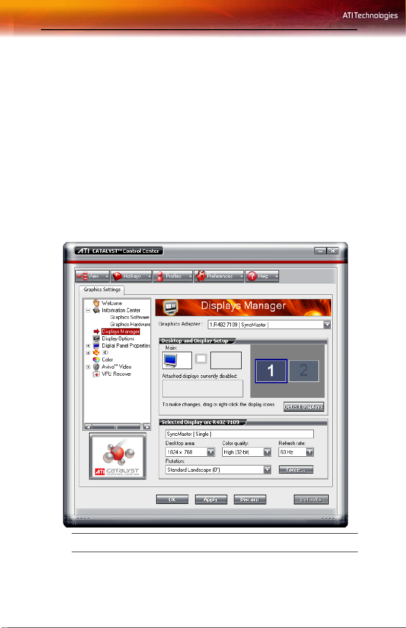
Displays Manager
The Displays Manager aspect is the central location for configuring your
display devices and arranging your desktop. Use the Displays Manager
aspect to quickly change your display setup, arrange your desktop in a
multi-monitor environment, and enable TV Out.
Those new to the Catalyst™ Control Center may use the Basic View
wizard to help you configure your display preferences. Experienced users
who prefer to manually configure their desktop setting should use the
Advanced View.
Note: The Catalyst™ Control Center will open to the Basic View the
very first time it is accessed. Experienced users can easily change to
Advanced View by selecting Advanced and click the Next button.
Catalyst™ Control Center: Displays Manager
Page 47

Displays Manager Advanced View 39
Displays Manager Advanced View
Use Display Manager Advanced View to set your desktop resolution, the
display refresh rate, and arrange your displays.
To change your display configuration requires dragging and/or clicking or
right-clicking a display icon
Access Displays Manager
• From the Tree Menu, click Displays Manager.
Enable a secondary display device
1 From the Tree View pane, click Displays Manager.
2 Click the number 2 display icon in the right-hand box.
3 Click Yes to the Enable this display dialog.
• Optionally, right-click the number 2 icon in the right-hand box
and click Enable in the pop-up menu.
Note: Repeat steps 2 and 3 above for each additional connected
device. The number on the display icon will increase as more displays
are added.
Enable Extended Mode
If the secondary display is disabled:
1 From the Tree View pane, click Displays Manager.
2 Click the number 2 display icon in the right-hand box.
3 Click Yes to the Enable this display? dialog.
• Optionally, right-click the number 2 icon in the right-hand box
and click Enable in the pop-up menu.
If the secondary display is in Clone mode, Vertical or Horizontal Stretch
mode:
1 Click and drag the display icon from the Clone box to Additional
Displays box.
2 Release the mouse button and click Remove display.
• Optionally, right-click the number 2 icon in the right-hand box
and click Disable in the pop-up menu.
3 Click the number 2 icon in the right-hand box.
Page 48

40 Displays Manager Advanced View
4 Click Yes to the Enable this display? dialog.
Enable Clone Mode
If the secondary device is disabled:
1 From the Tree View pane, click Displays Manager.
2 Click and drag the display device icon in Attached displays
currently disabled to the empty box to the right of the Main box.
3 Click Clone Main with [display device] in the pop-up menu.
If the secondary display is enabled:
1 Right click the display device icon in Deskto p 2 wh en in Extended
mode, Rightmost when in Stretch Horizontal mode, or Lower in
Stretch Vertical mode.
2 Click Clone Main with [display device].
3 Click Yes to the Displays Manager Notification dialog.
Note: Display device can be CRT, DFP, TV, or HDTV.
Enable Stretch Main Vertically
If the secondary display is disabled:
1 From the Tree View pane, click Displays Manager.
2 Click and drag the display device icon from Additional Displays to
the empty box to the right of the Main box.
3 Click Stretch vertically onto [display device] in the pop-up menu.
4 Click Yes in the Displays Manager Notification dialog.
If the secondary display is enabled:
1 Right click the display device icon in Deskto p 2 wh en in Extended
mode, Rightmost when in Stretch Horizontal mode, or Clone in Clone
mode.
2 Click Stretch vertically onto [display device] in the pop-up menu.
3 Click Yes in the Displays Manager Notification dialog.
Note: Display device can be CRT, DFP, TV, or HDTV.
Enable Stretch Main Horizontally
If the secondary display is disabled:
Page 49

Displays Manager Advanced View 41
1 From the Tree View pane, click Displays Manager.
2 Click and drag the display device icon from Additional Displays to
the empty box to the right of the Main box.
3 Click Stretch horizontally onto [display device].
If the secondary display is enabled:
1 Right click the display device icon in Deskto p 2 wh en in Extended
mode, or Lower in Stretch Vertical mode, or Clone in Clone Mod e.
2 Click Stretch horizontally onto [display device] in the pop-up
menu.
3 Click Yes to the Displays Manager Notification dialog.
Note: Display device can be CRT, DFP, TV, or HDTV depending on
the device connection.
Swap displays in Extended Mode
Use Swap displays to switch your desktops when using multiple monitors.
1 From the Tree View pane, click Displays Manager.
2 Right-click any Desktop icon.
3 Select Swap displays.
4 Click either Maintain per-display mode settings or Swap displays
order only.
Note: Swap displays order only swaps displays while maintaining
the existing display settings. Maintain per-display mode settings
swaps displays and display settings.
Swap displays in all other modes
Use Swap display mappings to switch your desktops when using multiple
monitors.
1 From the Tree View pane, click Displays Manager.
2 Right-click any Desktop icon.
3 Select Swap display mapping.
Change desktop size
1 From the Tree View pane, click Displays Manager.
2 Select a size from the Desktop Area drop-down menu.
Page 50

42 Displays Manager Advanced View
Change Color quality
1 From the Tree View pane, click Displays Manager.
2 Select the desired color setting from the Color Quality drop-down
menu.
Change display refresh rate
1 From the Tree View pane, click Displays Manager .
2 Choose a refresh rate from the Refresh Rate drop-down menu.
Note: See your monitor manual for supported refresh rates. Setting a
refresh rate higher than recommended by the monitor manufacturer
could damage the monitor.
Rotate the desktop
1 From the Tree View pane, click Displays Manager.
2 Right-click the desktop monitor icon to be rotated.
3 Select a rotation option from the pop-up menu.
• Optionally, select a rotation angle from the Rotation drop-down
menu.
Detect a newly connected display device
Detect a display device, such as a Digital Flat Panel or TV without having
to restart your computer
1 From the Tree View pane, click Displays Manager.
2 Click Detect Displays button.
Force changes to a specific display setting
You can force the Catalyst™ Control Center to override the display settings
required, or not allowed, by a specific application.
1 From the Tree View pane, click Displays Manager.
2 Click the Force button.
3 Use the mouse to cursor over to the display feature to force.
4 Highlight and then click the required setting.
Page 51

Display Options 43
Apply your settings
1 Click Apply to save your changes and leave the Catalyst™ Control
Center open.
2 Click OK to save your changes and exit the Catalyst™ Control
Center.
Discard your settings
•Click Discard to ignore any unsaved changes and restore the
settings that existed when the Catalyst™ Control Center was
opened or the last time Apply was used. Discard does not close the
Catalyst™ Control Center.
Clicking
the current view.
Discard applies to all features of an aspect, not just the feature in
Display Options
The Display Options aspect gives you additional control to optimize
performance of OpenGL® and Direct 3D® applications.
Use 3D Refresh Rate Override to set a refresh rate of your choice when a
full-screen application or game has a default refresh rate that is lower than
optimal.
Choose one of the Display Detection Options to prevent screen flicker
when detecting a display.
If you are using an older TV or one that has non-standard inputs that may
not be automatically detected, use Force TV Detection. When a TV is
detected using this method, it appears in the Displays Manager aspect and
can be configured as required. However, some features that rely on
automatic detection, such as extended desktop, will not be supported.
Page 52

44 Display Options
Catalyst™ Control Center: Display Options
Select a refresh rate override
Some applications may have a default refresh rate lower than the optimal
setting for your monitor. 3D Refresh Rate Override enables you to set the
refresh rate for full-screen applications or games utilizing Microsoft®
DirectX® or OpenGL®. You can either set an explicit refresh rate, or make
the refresh rate the same as the desktop, or disable this feature allowing the
application to set the refresh rate.
1 From the Tree View pane, click Display Options.
2 Select the desired refresh rate from the 3D Refresh Rate Override
drop-down menu.
Page 53

Display Options 45
Determine how display devices are detected
Use this feature to determine how the Catalyst™ Control Center detects
display devices connected to your computer. You can set the Catalyst™
Control Center to automatically detect all connected display devices when
it is opened or you can manually detect connected devices when they are
required.
1 From the Tree View pane, click Display Options.
2 Click either
• Detect whenever Catalyst™ Control Center is opened.
or
• Use manual detection only (I must click Detect Displays
button).
Note: The Detect Displays button is located on the Displays
Manager page.
Force TV detection
Use Force TV detection if your TV is not automatically detected by the
Catalyst™ Control Center and does not appear in the Displays Manager
page. This may be the case if your TV has non-standard inputs.
Note: If Force TV detection is required to detect your TV some
features that rely on automatic detection, such as extended desktop,
will not be supported.
1 From the Tree View pane, click Display Options.
2 Click Force TV detection enables this feature.
Note: This option is not available if the installed graphics card does
not support TV Out.
Set resolution modes for devices with limited resolution
capabilities
1 From the Tree View pane, click Display Options.
2 Select one of the following from the For displays of limited
resolution capabilities drop-down menu:
• List only those modes supported by all displays
• Only allow panning on limited-resolution displays
• List all possible modes (including panning modes).
Page 54

46 Monitor Properties
Apply your settings
1 Click Apply to save your changes and leave the Catalyst™ Control
Center open.
2 Click OK to save your changes and exit the Catalyst™ Control
Center.
Discard your settings
•Click Discard to ignore any unsaved changes and restore the
settings that existed when the Catalyst™ Control Center was
opened or the last time Apply was used. Discard does not close the
Catalyst™ Control Center.
Clicking
the current view.
Restore default settings
Discard applies to all features of an aspect, not just the feature in
1 Move the mouse to the bottom right-hand corner of the window.
2 Click Defaults.
Note: Clicking Defaults will restore the defaults for the current view
only. Previous settings are not altered and will be saved once you
click OK.
Monitor Properties
Use the Monitor Properties aspect to configure your Display Data Channel
(DDC) monitor’s attributes, to display information about the connected
monitor, and adjust the output display’s position and size.
Note: Catalyst™ Control Center loads aspects dynamically based on
what device is attached to the graphics card. If you have a display
device other than a standard monitor or flat panel display (such as a
HDTV screen) Digital Panel Properties will appear in the Graphics
Settings listing instead of Monitor Properties.
Page 55

Monitor Attributes 47
Catalyst™ Control Center: Monitor Properties (Sample)
Monitor Attributes
Monitor Attributes provides information about the attached monitor. You
can also enable Extended Display Identification Data.
Extended Display Identification Data (EDID) uses the information
provided by the attached monitor to determine the limits for the resolution
and refresh rate.
Enable Extended Display Identification Data (EDID)
1 From the Tree View pane, expand Monitor Properties.
2 Click Attributes.
3 Select Use Extended Display Identification Data (EDID) or driver
defaults to place a check mark in the check box.
Page 56

48 Digital Panel Properties
Apply your settings
1 Click Apply to save your changes and leave the Catalyst™ Control
Center open.
2 Click OK to save your changes and exit the Catalyst™ Control
Center.
Restore default settings
1 Move the mouse to the bottom right-hand corner of the window.
2 Click Defaults.
Note: Clicking Defaults will restore the defaults for the current view
only. Previous settings are not altered and will be saved once you
click OK.
Discard your settings
•Click Discard to ignore any unsaved changes and restore the
settings that existed when the Catalyst™ Control Center was
opened or the last time Apply was used. Discard does not close the
Catalyst™ Control Center.
Clicking
the current view.
Discard applies to all features of an aspect, not just the feature in
Digital Panel Properties
Use the Digital Panel Properties aspect to configure the DVI settings and
Image Scaling to improve image quality without impacting performance.
Use HDTV Support to add EDID information (containing information
about the capabilities of the display) about your connected HDTV display
to the Force button in Displays Manager.
Note: Catalyst™ Control Center loads aspects dynamically based on
what device is attached to the graphics card. If you have standard
display device such as a CRT monitor or flat panel display Monitor
Properties will appear instead of Digital Panel Properties. The latter
is designed for use with such devices as HDTV displays.
Page 57

Attributes 49
Catalyst™ Control Center: Digital Panel Properties (Sample)
Attributes
Digital Panel Attributes provides information about the connected digital
display. Use DVI Settings and Image Scaling to configure your digital
display.
Set Image Scaling
1 From the Tree View pane, expand Digita l Panel Properties.
2 Click Attributes.
3 Under Image Scaling, click to enable the desired setting.
Note: Enable Scale image to full panel size to fill the digital
display.
Page 58

50 Attributes
Note: Use centered timings optimizes the display timing standards
used on a high-end digital panel. Enable this feature to stop display
flicker.
Adjust the DVI Settings
1 From the Tree View pane, expand Digita l Panel Properties.
2 Click Attributes.
3 Under DVI Settings, click to enable the desired setting.
Note: Reducing DVI frequency on high-resolution displays can
resolve either display corruption or the complete absence of any
image when a display is set to a high resolution. This should only be
enabled if the Digital Panel is experiencing these types of problems.
Note: Alternate DVI operational mode, when enabled, may eliminate
display corruption.
Apply your settings
1 Click Apply to save your changes and leave the Catalyst™ Control
Center open.
2 Click OK to save your changes and exit the Catalyst™ Control
Center.
Restore default settings
1 Move the mouse to the bottom right-hand corner of the window.
2 Click Defaults.
Note: Clicking Defaults will restore the defaults for the current view
only. Previous settings are not altered and will be saved once you
click OK.
Discard your settings
•Click Discard to ignore any unsaved changes and restore the
settings that existed when the Catalyst™ Control Center was
opened or the last time Apply was used. Discard does not close the
Catalyst™ Control Center.
Clicking
the current view.
Discard applies to all features of an aspect, not just the feature in
Page 59

Avivo™ Color 51
Avivo™ Color
Use Avivo™ Color with ATI graphics cards that supports per-display color
settings. Independently set the hue, saturation, and color temperature for
each attached and enabled display.
Set Hue
Refers to a specific color within the visible spectrum of light, defined by its
dominant wavelength.
1 From the Tree View pane, expand Digita l Panel Properties.
2 Click Avivo™ Color .
3 Adjust the Hue control slider to the desired position.
Set Saturation
Saturation refers to the intensity of a color in an i mag e.
1 From the Tree View pane, expand Digita l Panel Properties.
2 Click Avivo™ Color.
3 Click and drag the Saturation control slider to the desired position.
Set Color Temperature
Color temperature is a measure that compares a color to the light radiated
from an equivalent incandescent black body at a given temperature in
degrees Kelvin.
1 From the Tree View pane, expand Digita l Panel Properties.
2 Click Avivo™ Color.
3 Adjust the Temperature control slider to the desired position.
Apply your settings
1 Click Apply to save your changes and leave the Catalyst™ Control
Center open.
2 Click OK to save your changes and exit the Catalyst™ Control
Center.
Restore default settings
1 Move the mouse to the bottom right-hand corner of the window.
2 Click Defaults.
Page 60

52 HDTV Support
Note: Clicking Defaults will restore the defaults for the current view
only. Previous settings are not altered and will be saved once you
click OK.
Discard your settings
•Click Discard to ignore any unsaved changes and restore the
settings that existed when the Catalyst™ Control Center was
opened or the last time Apply was used. Discard does not close the
Catalyst™ Control Center.
Clicking
the current view.
Discard applies to all features of an aspect, not just the feature in
HDTV Support
Use HDTV Support when your CRT or DFP device supports one or more
HDTV modes that are not initially listed in the Displays Manager due to an
incomplete EDID. Selecting one or both of the HDTV modes adds them to
the Force button located in the Displays Manager when the associated
display is selected.
If you have a CRT and DFP device and want both to support HDTV, you
must go to both HDTV Support pages and select both Add 720p and Add
1080i check boxes.
L
Add 720p mode to the Displays Manager Force button
If the Predefined and Custom HDTV Formats list box is empty you can
add a format.
1 From the Tree View pane, expand Digita l Panel Properties.
WARNING!: Forcing a display mode that exceeds its EDID
limits may result in permanent damage to your display!
2 Click HDTV Support.
3 Click Add 720p standard format to the Displays Manager.
L
WARNING!: This option is only intended for disp lays that
report incomplete or incorrect EDID in fo rmation. Adding
this setting could damage your digital flat panel display.
USE WITH CAUTION!
Page 61

HDTV Support 53
Add 1080i mode to the Displays Manager Force button
If the Predefined and Custom HDTV Formats list box is empty you can
add a format.
1 From the Tree View pane, expand Digita l Panel Properties.
2 Click HDTV Support.
3 Click Add 1080i standard format to the Displays Manager.
L
Add 1080p mode to the Displays Manager Force button
If the Predefined and Custom HDTV Formats list box is empty you can
add a format.
WARNING!: This option is only intended for disp lays that
report incomplete or incorrect EDID in fo rmation. Adding
this setting could damage your digital flat panel display.
USE WITH CAUTION!
1 From the Tree View pane, expand Digita l Panel Properties.
2 Click HDTV Support.
3 Click Add 1080p standard format to the Displays Manager.
L
Add an HDTV format
The Predefined and Custom HDTV Formats list box should list any
standard and optimized HDTV formats supported by the digital panel’s
EDID. If the list is empty, then no HDTV formats are natively supported.
WARNING!: This option is only intended for disp lays that
report incomplete or incorrect EDID in fo rmation. Adding
this setting could damage your digital flat panel display.
USE WITH CAUTION!
1 From the Tree View pane, expand Digita l Panel Properties.
2 Click HDTV Support.
3 Select either 720p or 1080i in HDTV modes supported by this
display.
4 Click Apply formats.
5 Click Add.
Page 62

54 HDTV Support
• A group of four arrow buttons and a large rectangle is overlaid on
the screen. Use these arrows to increase or decrease the width and
height of the rectangle until the blue background is just visible.
•Click Maintain aspect ratio to maintain the ratio between width
and height while making adjustments.
6 Click Accept.
7 Click OK in the HDTV Format warning message box.
8 Click Apply to add your new HDTV format to the Predefined and
Custom HDTV Formats list and the Displays Manager mode list.
Note: The format to be added must be based on one of the standard
timing formats (720p or 1080i).
Remove an HDTV Format
1 From the Tree View pane, expand Digital Panel Properties.
2 Click HDTV Support.
3 Click to highlight the HDTV format to be removed in the Predefined
and Custom HDTV Formats list box.
4 Click Remove button.
Note: The removed format will be removed from the Displays
Manager mode list once the computer has been rebooted.
Apply HDTV Format
1 From the Tree View pane, expand Digital Panel Properties.
2 Click HDTV Support.
3 Click to highlight the desired an HDTV format in the Predefined and
Custom HDTV Formats list box.
4 Click Apply Format.
Apply your settings
1 Click Apply to save your changes and leave the Catalyst™ Control
Center open.
2 Click OK to save your changes and exit the Catalyst™ Control
Center.
Page 63

Restore default settings
1 Move the mouse to the bottom right-hand corner of the window.
2 Click Defaults.
Note: Clicking Defaults will restore the defaults for the current view
only. Previous settings are not altered and will be saved once you
click OK.
Discard your settings
•Click Discard to ignore any unsaved changes and restore the
settings that existed when the Catalyst™ Control Center was
opened or the last time Apply was used. Discard does not close the
Catalyst™ Control Center.
3D 55
Clicking
the current view.
Discard applies to all features of an aspect, not just the feature in
3D
Use 3D to adjust features found in 3D applications, such as graphic-design,
CAD programs and games.
3D is only available in advanced view. Use 3D to individually configure
the following settings:
• Standard Settings
• Anti-aliasing
• Anisotropic Filtering
• Catalyst™ A.I.
• Mipmap Detail Level
•API-Specific
Page 64

56 Standard Settings
Catalyst™ Control Center: Standard Settings
Standard Settings
The Standard settings page provides access to a universal slider control
where you can simultaneously adjust all of the standard 3D settings for any
type of 3D application. The slider enables you to adjust for overall system
performance, overall 3D image quality, or a balance between the two.
This page is useful when you are not aware of which type of 3D settings
your application uses, or when you want to use an overall adjustment
control that rapidly configures your application.
Adjust your Standard settings
The default selection is Balanced.
1 From the Tree View, click 3D.
2 Click Standard Settings.
Page 65

Anti-aliasing 57
3 Select Use custom settings to place a check mark in the check box.
4 Click and drag the Control slider to the left to select High or Optimal
Performance, or to the right to select High or Optimal Quality.
Preview your changes
• The preview image automatically displays your adjustments.
Optionally, double-click 3D Preview for a full-screen view of the
adjustments you have made. To exit full-screen Preview, press the Esc key.
The Preview can be disabled by clicking the “X” button in the Preview
pane. It can also be paused by clicking the “||” button in the Preview pane.
Clicking the pause button again causes the preview to resume.
Apply your settings
1 Click Apply to save your changes and leave the Catalyst™ Control
Center open.
2 Click OK to save your changes and exit the Catalyst™ Control
Center.
Discard your settings
•Click Discard to ignore any unsaved changes and restore the
settings that existed when the Catalyst™ Control Center was
opened or the last time Apply was used. Discard does not close the
Catalyst™ Control Center.
Clicking
the current view.
Restore default settings
Discard applies to all features of an aspect, not just the feature in
1 Move the mouse to the bottom right-hand corner of the window.
2 Click Defaults.
Note: Clicking Defaults will restore the defaults for the current view
only. Previous settings are not altered and will be saved once you
click OK.
Anti-aliasing
Anti-aliasing is a technique used to smooth out the jagged edges of threedimensional curved objects or objects with diagonal edges.
Page 66

58 Set the Anti-Aliasing preference manually
Anti-aliasing can be set to favor either an increase in system processing
performance or improved image quality:
• Setting for performance is best used when the 3D image is
animated and smoothness of motion is the most important
consideration.
• Setting for quality is best used when having highly detailed and
realistic 3D objects is the primary concern.
• If you are unsure of how to configure anti-aliasing, use the Let the
Application Decide option. Your display will automatically adjust
to the application’s requirements.
Set the Anti-Aliasing preference manually
Set the Anti-Aliasing preference manually
1 From the Tree View pane, expand 3D.
2 Click Anti-aliasing.
3 Ensure the application override is disabled. To do so, make sure the
Let the Application Decide check box is cleared. The slider control
will become available.
4 Click the Control slider and move the selector to your preferred
setting:
• To increase processing performance, move the slider to the left.
• T o increase image quality, move the slider to the right.
Set Temporal anti-aliasing (using SmoothVision™ HD)
Increases image quality without impacting performance by taking fewer
image samples but at a faster rate.
1 From the Tree View pane, expand 3D.
2 Click Anti-Aliasing.
3 Uncheck Let the application decide.
4 Check Temporal anti-aliasing.
Set the level of adaptive anti-aliasing
1 From the Tree View pane, expand 3D.
2 Click Adaptive Anti-Aliasing.
Page 67

Adaptive Anti-aliasing 59
3 Adjust the Adaptive Anti-Aliasing control slider to the desired
setting.
Preview your changes
• The preview image automatically displays your adjustments.
Optionally, double-click 3D Preview for a full-screen view of the
adjustments you have made. To exit full-screen Preview, press the Esc key.
The Preview can be disabled by clicking the “X” button in the Preview
pane. It can also be paused by clicking the “||” button in the Preview pane.
Clicking the pause button again causes the preview to resume.
Apply your settings
1 Click Apply to save your changes and leave the Catalyst™ Control
Center open.
2 Click OK to save your changes and exit the Catalyst™ Control
Center.
Discard your settings
•Click Discard to ignore any unsaved changes and restore the
settings that existed when the Catalyst™ Control Center was
opened or the last time Apply was used. Discard does not close the
Catalyst™ Control Center.
Clicking
the current view.
Restore default settings
Discard applies to all features of an aspect, not just the feature in
1 Move the mouse to the bottom right-hand corner of the window.
2 Click Defaults.
Note: Clicking Defaults will restore the defaults for the current view
only. Previous settings are not altered and will be saved once you
click OK.
Adaptive Anti-aliasing
Adaptive anti-aliasing is a technique that applies a combination of multisampling (MSAA) and super-sampling (SSAA) on 3D objects to improve
edge smoothness and fine detail. This feature renders 3D objects containing
Page 68

60 Anisotropic Filtering
transparencies more realistic, providing exceptional levels of image quality
while maintaining performance.
Set the level of adaptive anti-aliasing
1 From the Tree View pane, expand 3D.
2 Click Adaptive Anti-Aliasing.
3 Adjust the Adaptive Anti-Aliasing control slider to the desired
setting.
Anisotropic Filtering
Anisotropic filtering is a technique that preserves detail on surfaces that
have three-dimensional perspective and fade away into the background. It
works best when used in conjunction with Mipmapping.
Anisotropic filtering can be set to favor either an increase in system
processing performance or improved image quality:
• Setting for performance is best used with applications that display
objects with smooth, simple surfaces, such as those seen in CAD
applications.
• Setting for quality is best used with applications that display highly
detailed scenes, backgrounds, and textured objects, such as those
seen in 3D games.
• If you are unsure how to configureanisotropic filtering, use the
the Application Decide
adjust to the application’s requirements.
option. Yo ur display wi ll automatically
Let
Set the Anisotropic Filtering preference manually
1 From the Tree View pane, expand 3D.
2 Click Anisotropic Filtering.
3 Ensure the application override is disabled. To do so, make sure the
Let the Application Decide check box is cleared. The slider control
will become available.
4 Click the Control slider and move the selector to your preferred
setting:
• To increase processing performance, move the slider to the left.
• T o increase image quality, move the slider to the right.
Page 69

Anisotropic Filtering 61
Set the Anisotropic Filtering to automated preference
1 From the Tree View pane, expand 3D.
2 Click Anisotropic Filtering.
3 Ensure the application override is enabled. To do so, make sure the
Let the Application Decide check box is selected.
Note: The slider control becomes unavailable.
Set higher quality Anisotropic Filtering
1 From the Tree View pane, expand 3D.
2 Click Anisotropic Filtering.
3 Select Enable High Quality AF.
Note: Enabling this feature may impact performance.
Note: This feature is not supported by all ATI graphics cards.
Preview your changes
• The preview image automatically displays your adjustments.
Optionally, double-click 3D Preview for a full-screen view of the
adjustments you have made. To exit full-screen Preview, press the Esc key.
The Preview can be disabled by clicking the “X” button in the Preview
pane. It can also be paused by clicking the “||” button in the Preview pane.
Clicking the pause button again causes the preview to resume.
Apply your settings
1 Click Apply to save your changes and leave the Catalyst™ Control
Center open.
2 Click OK to save your changes and exit the Catalyst™ Control
Center.
Discard your settings
•Click Discard to ignore any unsaved changes and restore the
settings that existed when the Catalyst™ Control Center was
opened or the last time Apply was used. Discard does not close the
Catalyst™ Control Center.
Clicking
the current view.
Discard applies to all features of an aspect, not just the feature in
Page 70

62 Catalyst™ A.I.
Restore default settings
1 Move the mouse to the bottom right-hand corner of the window.
2 Click Defaults.
Note: Clicking Defaults will restore the defaults for the current view
only. Previous settings are not altered and will be saved once you
click OK.
Catalyst™ A.I.
Catalyst™ A.I. makes use of ATI’s new texture analyzer technology to
optimize performance in 3D applications while maintaining or even
improving image quality. It analyzes individual textures as they are loaded
to determine the best and fastest way to display them.
Use the Standard slider setting to achieve optimal results without impacting
performance. Use the Advanced slider setting to achieve even better results
with minimal impact on performance.
Catalyst™ A.I. includes application-specific detection for various games
and games engines such as Doom 3, the Half Life 2 engine, Unreal
Tournament 2003, Unreal Tournament 2004, Splinter Cell, Race Driver,
Prince of Persia, and Crazy Taxi 3.
Disable Catalyst™ A.I.
1 From the Tree View pane, expand 3D.
2 Select Catalyst™ A.I.
3 Select Disable Catalyst™ A.I. to place a check mark in the check
box.
Set Catalyst™ A.I. settings
1 From the Tree View pane, expand 3D.
2 Click Catalyst™ A.I.
3 If necessary, clear the check mark from Disable Catalyst™ A.I.
4 Click and drag to slider to the desired setting.
Preview your changes
• The preview image automatically displays your adjustments.
Page 71

Mipmap Detail Level 63
Optionally, double-click 3D Preview for a full-screen view of the
adjustments you have made. To exit full-screen Preview, press the Esc key.
The Preview can be disabled by clicking the “X” button in the Preview
pane. It can also be paused by clicking the “||” button in the Preview pane.
Clicking the pause button again causes the preview to resume.
Apply your settings
1 Click Apply to save your changes and leave the Catalyst™ Control
Center open.
2 Click OK to save your changes and exit the Catalyst™ Control
Center.
Discard your settings
•Click Discard to ignore any unsaved changes and restore the
settings that existed when the Catalyst™ Control Center was
opened or the last time Apply was used. Discard does not close the
Catalyst™ Control Center.
Clicking
the current view.
Restore default settings
Discard applies to all features of an aspect, not just the feature in
1 Move the mouse to the bottom right-hand corner of the window.
2 Click Defaults.
Note: Clicking Defaults will restore the defaults for the current view
only. Previous settings are not altered and will be saved once you
click OK.
Mipmap Detail Level
Mipmapping is a texturing technique that preserves the detail on a 3D
object’s surface as it moves into the background. A series of high- and lowresolution texture maps are stored in memory and selectively used to create
the object’s surface, depending on what level of detail is needed.
Mipmap detail level can be set to favor either an increase in system
processing performance or improved image quality:
• Setting for performance is best used when the 3D image is
animated and smoothness of motion is the most important
consideration.
Page 72

64 Mipmap Detail Level
• Setting for quality is best used when high surface detail is required,
especially if the animated object rotates or moves into the
background.
Set the Mipmap detail level
1 From the Tree View pane, expand 3D.
2 Click Mipmap Detail Level.
3 Click the Control slider and move the selector to the left to increase
processing performance, or to the right to increase image quality.
Preview your changes
• The preview image automatically displays your adjustments.
Optionally, double-click 3D Preview for a full-screen view of the
adjustments you have made. To exit full-screen Preview, press the Esc key.
The Preview can be disabled by clicking the “X” button in the Preview
pane. It can also be paused by clicking the “||” button in the Preview pane.
Clicking the pause button again causes the preview to resume.
Apply your settings
1 Click Apply to save your changes and leave the Catalyst™ Control
Center open.
2 Click OK to save your changes and exit the Catalyst™ Control
Center.
Discard your settings
•Click Discard to ignore any unsaved changes and restore the
settings that existed when the Catalyst™ Control Center was
opened or the last time Apply was used. Discard does not close the
Catalyst™ Control Center.
Clicking
the current view.
Restore default settings
Discard applies to all features of an aspect, not just the feature in
1 Move the mouse to the bottom right-hand corner of the window.
2 Click Defaults.
Note: Clicking Defaults will restore the defaults for the current view
only. Previous settings are not altered and will be saved once you
click OK.
Page 73

All Settings 65
Preview your changes
• The preview image automatically displays your adjustments.
Optionally, double-click 3D Preview for a full-screen view of the
adjustments you have made. To exit full-screen Preview, press the Esc key.
The Preview can be disabled by clicking the “X” button in the Preview
pane. It can also be paused by clicking the “||” button in the Preview pane.
Clicking the pause button again causes the preview to resume.
Apply your settings
1 Click Apply to save your changes and leave the Catalyst™ Control
Center open.
2 Click OK to save your changes and exit the Catalyst™ Control
Center.
Discard your settings
•Click Discard to ignore any unsaved changes and restore the
settings that existed when the Catalyst™ Control Center was
opened or the last time Apply was used. Discard does not close the
Catalyst™ Control Center.
Clicking
the current view.
Restore default settings
Discard applies to all features of an aspect, not just the feature in
1 Move the mouse to the bottom right-hand corner of the window.
2 Click Defaults.
Note: Clicking Defaults will restore the defaults for the current view
only. Previous settings are not altered and will be saved once you
click OK.
All Settings
The All Settings page combines all of the principal 3D features onto a
single page, without any preview window, allowing for quick access and
adjustment. You can change the settings for the following 3D features as
you normally would on each feature’s own page:
• Anti-aliasing
• Anisotropic filtering
Page 74

66 Set the Anti-Aliasing preference manually
• Catalyst™ A.I.
• Mipmap detail level
• Wait for display refresh
• SmartShader™ Effects
• Adaptive Anti-Aliasing
This page is useful when it is not necessary to preview the adjusted settings
because the effect is already known or understood.
Set the Anti-Aliasing preference manually
1 From the Tree View pane, expand 3D.
2 Click All Settings.
3 Ensure the application override is disabled. To do so, make sure the
Let the Application Decide check box is cleared. The slider control
will become available.
4 Click the Control slider and move the selector to your preferred
setting:
• To increase processing performance, move the slider to the left.
• T o increase image quality, move the slider to the right.
Set the level of adaptive anti-aliasing
1 From the Tree View pane, expand 3D.
2 Click Adaptive Anti-Aliasing.
3 Adjust the Adaptive Anti-Aliasing control slider to the desired
setting.
Set the Anisotropic Filtering preference manually
1 From the Tree View pane, expand 3D.
2 Click All Settings.
3 Ensure the application override is disabled. To do so, make sure the
Let the Application Decide check box is cleared. The slider control
will become available.
4 Click the Control slider and move the selector to your preferred
setting:
• To increase processing performance, move the slider to the left.
• T o increase image quality, move the slider to the right.
Page 75

Set the Anti-Aliasing preference manually 67
Set the Anisotropic Filtering to automated preference
1 From the Tree View pane, expand 3D.
2 Click All Settings.
3 Ensure the application override is enabled. To do so, make sure the
Let the Application Decide check box is selected.
Note: The slider control becomes unavailable.
Set the Catalyst™ A.I. setting
1 From the Tree View pane, expand 3D.
2 Click All Settings.
3 Scroll to Catalyst™ A.I.
4 Click the Control slider and move the selector to the left to increase
processing performance, or to the right to increase image quality.
Set the Mipmap detail level
1 From the Tree View pane, expand 3D.
2 Click All Settings.
3 Scroll to Mipmap Detail Level.
4 Click the Control slider and move the selector to the left to increase
processing performance, or to the right to increase image quality.
Set Wait for vertical refresh setting
1 From the Tree View pane, expand 3D.
2 Click All Settings.
3 Scroll to Wait for vertical refresh.
4 Click the Control slider and move the selector to the left to increase
processing performance, or to the right to increase image quality.
Apply your settings
1 Click Apply to save your changes and leave the Catalyst™ Control
Center open.
2 Click OK to save your changes and exit the Catalyst™ Control
Center.
Page 76

68 API Specific
Discard your settings
•Click Discard to ignore any unsaved changes and restore the
settings that existed when the Catalyst™ Control Center was
opened or the last time Apply was used. Discard does not close the
Catalyst™ Control Center.
Clicking
the current view.
Restore default settings
Discard applies to all features of an aspect, not just the feature in
1 Move the mouse to the bottom right-hand corner of the window.
2 Click Defaults.
Note: Clicking Defaults will restore the defaults for the current view
only. Previous settings are not altered and will be saved once you
click OK.
API Specific
Use the API Specific dialog to select settings that are exclusively for the
Direct 3D® and OpenGL® Application Programmable Interfaces (API).
These settings are provided for resolving certain incompatibilities within
3D applications that use one of these APIs.
Use this dialog when you are know which type of API (Direct 3D® or
OpenGL®) your 3D application uses, and you want to select a particular
API-specific feature.
If you are not sure which API your 3D application uses, consult the
documentation of your 3D application.
Set Enable geometry instancing
Geometry Instancing allows the GPU to create multiple objects from a
single geometric model, rather than passing an entire new model for each
item on the screen. This increases the rendering speed of images such as
leaves, or grass.
1 From the Tree View pane, expand 3D.
2 Click API Specific.
3 Select Enable geometry instancing to place a check mark in the
check box.
Page 77

API Specific 69
Set Support DXT texture formats for Direct 3D®
This option enables support for DirectX® compressed texture formats.
DXT requires half the amount of memory to draw the same amount of
textures. This frees up memory while achieving high quality graphics.
1 From the Tree View pane, expand 3D.
2 Click API Specific.
3 Select Support DXT texture formats to place a check mark in the
check box.
Set Alternate pixel center for Direct 3D®
This might eliminate problems with certain Direct 3D® games that display
vertical and horizontal lines around textures or display text incorrectly.
This setting should only be enabled if you are experiencing these issues, as
it may cause problems in other games.
1 From the Tree View pane, expand 3D.
2 Click API Specific.
3 Select Alternate pixel center to place a check mark in the check box.
Set Triple buffering for OpenGL®
Enabling Triple buffering will improve the frame rate of games when
vertical sync is enabled, only if the frame rate is less than the vertical sync
refresh rate. In low memory situations, enabling Triple buffering may
decrease application performance as there will be less frame buffer
memory available for texture and geometry data. If there is insufficient
memory available to support Triple buffering, it will automatically be
disabled.
1 From the Tree View pane, expand 3D.
2 Click API Specific.
3 Select Triple buffering to place a check mark in the check box.
Set Force 24-bit Z-buffer depth for OpenGL®
Enables you to explicitly set the Z-buffer depth. Most applications will
work best with the Disabled setting.
1 From the Tree View pane, expand 3D.
2 Click API Specific.
Page 78

70 Color
3 Select Force 24-bit Z-buffer depth to place a check mark in the
check box.
Apply your settings
1 Click Apply to save your changes and leave the Catalyst™ Control
Center open.
2 Click OK to save your changes and exit the Catalyst™ Control
Center.
Restore default settings
1 Move the mouse to the bottom right-hand corner of the window.
2 Click Defaults.
Note: Clicking Defaults will restore the defaults for the current view
only. Previous settings are not altered and will be saved once you
click OK.
Discard your settings
•Click Discard to ignore any unsaved changes and restore the
settings that existed when the Catalyst™ Control Center was
opened or the last time Apply was used. Discard does not close the
Catalyst™ Control Center.
Clicking
the current view.
Discard applies to all features of an aspect, not just the feature in
Color
Use the Color page to adjust the color properties of your Desktop and Fullscreen 3D applications and games. Use the Color Correction Images to
preview the changes before applying them.
The Color curve is a graphical representation of all the values of gamma,
brightness, or contrast. The color curve line will reflect any changes made
to these elements.
To access the Color aspect
• From the Tree View pane, click Color.
Page 79

Color Desktop 71
Catalyst™ Control Center: Color
Color Desktop
Adjust the overall richness of color by using the Gamma control. To adjust
the overall brightness use the
use the
Contrast control.
Display Color page to configure Desktop
1 From the Tree View pane, click Color.
2 Select Desktop from the Set color correction for drop-down menu.
Set Gamma, Brightness, and Contrast simultaneously
1 From the Tree View pane, click Color.
2 Select Desktop in Set color correction for.
3 Select All Channels.
Brightness control, and the overall contrast
Page 80

72 Color Desktop
4 Click and drag either the Gamma, Brightness, or Contrast to adjust all
these settings simultaneously.
Revert to last known All Channel settings
1 From the Tree View pane, click Color.
2 Select Desktop in Set color correction for.
3 Select All Channels.
Reactivate your color settings
Your desktop may retain the color settings when exiting an application or
game. Should this be the case the gamma, brightness, and contrast sliders
are disabled. The Reactivate ATI color controls button resets the sliders
to their previous settings.
1 From the Tree View pane, click Color.
2 Click Reactivate ATI color controls button.
Set Color Gamma
1 From the Tree View pane, click Color.
2 Click and drag the Control slider to your pr eferred setting:
• To increase the Gamma, move the slider to the right.
• To decrease the Gamma, move the slider to the left.
• Optionally, click the up and down arrow buttons of the
adjustment box.
Click the Reset button to restore the previous settings.
Note: The preview image automatically displays the adjustments you
have made.
Set Color Brightness
1 From the Tree View pane, click Color.
2 Click and drag the Control slider to your prefer red setting:
• To increase the Brightness, move the slider to the right.
• To decrease the Brightness, move the slider to the left.
• Optionally, click the up and down arrow buttons in the
adjustment box.
Click the Reset button to restore the previous settings.
Page 81

Color Desktop 73
Note: The preview image automatically displays the adjustment you
have made.
Set Color Contrast
1 From the Tree View pane, click Color.
2 Click and drag the Control slider to your prefer red setting:
• To increase the Contrast, move the slider to the right.
• To decrease the Contrast, move the slider to the left.
• Optionally, click the up and down arrow buttons in the
adjustment box.
Click the Reset button to restore the previous settings.
Note: The preview image automatically displays the adjustment you
have made.
Apply your settings
1 Click Apply to save your changes and leave the Catalyst™ Control
Center open.
2 Click OK to save your changes and exit the Catalyst™ Control
Center.
Restore default settings
1 Move the mouse to the bottom right-hand corner of the window.
2 Click Defaults.
Note: Clicking Defaults will restore the defaults for the current view
only. Previous settings are not altered and will be saved once you
click OK.
Discard your settings
•Click Discard to ignore any unsaved changes and restore the
settings that existed when the Catalyst™ Control Center was
opened or the last time Apply was used. Discard does not close the
Catalyst™ Control Center.
Clicking
the current view.
Discard applies to all features of an aspect, not just the feature in
Page 82

74 Color - FullScreen 3D
Color - FullScreen 3D
Adjusting the Gamma control alters the overall richness of color. Adjusting
the
Brightness control alters the overall brightness. Adjusting the Contrast
control alters the overall contrast.
• Adjusting the Gamma can be useful for CAD applications that rely
heavily on color coding or applications that require realistic color.
• Adjusting the Brightness and Contrast can be useful for 3D games
that display dimly lit scenes.
Display Color page to configure FullScreen 3D
1 From the Tree View pane, click Color.
2 Select FullScreen 3D from the Set color correction for: drop-down
menu.
Set Color Gamma
1 From the Tree View pane, click Color.
2 Click and drag the Control slider to your pr eferred setting:
• To increase the Gamma, move the slider to the right.
• To decrease the Gamma, move the slider to the left.
• Optionally, click the up and down arrow buttons of the
adjustment box.
Click the Reset button to restore the previous settings.
Note: The preview image automatically displays the adjustments you
have made.
Set Color Contrast
1 From the Tree View pane, click Color.
2 Click and drag the Control slider to your prefer red setting:
• To increase the Contrast, move the slider to the right.
• To decrease the Contrast, move the slider to the left.
• Optionally, click the up and down arrow buttons in the
adjustment box.
Click the Reset button to restore the previous settings.
Note: The preview image automatically displays the adjustment you
have made.
Page 83

Avivo™ Video for Radeon® Series starting from 9500 75
Apply your settings
1 Click Apply to save your changes and leave the Catalyst™ Control
Center open.
2 Click OK to save your changes and exit the Catalyst™ Control
Center.
Restore default settings
1 Move the mouse to the bottom right-hand corner of the window.
2 Click Defaults.
Note: Clicking Defaults will restore the defaults for the current view
only. Previous settings are not altered and will be saved once you
click OK.
Discard your settings
•Click Discard to ignore any unsaved changes and restore the
settings that existed when the Catalyst™ Control Center was
opened or the last time Apply was used. Discard does not close the
Catalyst™ Control Center.
Clicking
the current view.
Discard applies to all features of an aspect, not just the feature in
Avivo™ Video for Radeon® Series
starting from 9500
Use the Avivo™ Video aspect to apply standard video settings with a
Wizard or selecting a video preset. Use Adjustments to configure gamma,
brightness, and hue. Use Theater Mode to set aspect ratio and overlay
display mode. Preview your changes before applying them.
Page 84

76 Standard Settings
Catalyst™ Control Center: Avivo Video
Standard Settings
To quickly adjust your video settings choose one of the video presets or use
the Video Wizard to configure your display devices.
Start the Video Wizard
1 From the Tree View pane, expand Video.
2 Click Standard Settings.
3 Click the Wizard button.
Select a Video Preset
1 From the Tree View pane, expand Video.
2 Click Standard Settings.
Page 85

Standard Settings 77
3 Select a preset from the Video Presets menu.
Apply your settings
1 Click Apply to save your changes and leave the Catalyst™ Control
Center open.
2 Click OK to save your changes and exit the Catalyst™ Control
Center.
Restore default settings
1 Move the mouse to the bottom right-hand corner of the window.
2 Click Defaults.
Note: Clicking Defaults will restore the defaults for the current view
only. Previous settings are not altered and will be saved once you
click OK.
Discard your settings
•Click Discard to ignore any unsaved changes and restore the
settings that existed when the Catalyst™ Control Center was
opened or the last time Apply was used. Discard does not close the
Catalyst™ Control Center.
Clicking
the current view.
Discard applies to all features of an aspect, not just the feature in
Adjustments
Use Avivo™ Video Adjustments to manually set Gamma, Brightness,
Contrast, Saturation, and Hue.
Let the application control the video adjustments
1 From the Tree View pane, expand Vide o.
2 Click Adjustments.
3 Click Let the application control the video adjustments.
Set Gamma
Gamma controls the overall intensity of a video image.
1 From the Tree View pane, expand Video.
2 Click Adjustments.
Page 86

78 Standard Settings
3 Click and drag the Gamma control slider to the desired position.
Set Contrast
Contrast is the difference between the brightest and darkest parts of an
image.
1 From the Tree View pane, expand Video.
2 Click Adjustments.
3 Click and drag the Contrast control slider to the desired position.
Set Brightness
Brightness is the overall intensity, or luminosity of an image.
1 From the Tree View pane, expand Video.
2 Click Adjustments.
3 Click and drag the Brightness control slider to the desired position.
Set Saturation
Saturation is the measure of amount of color in an image.
1 From the Tree View pane, expand Video.
2 Click Adjustments.
3 Click and drag the Saturation control slider to the desired position.
Set Hue
Hue defines the tint of the red, green, and blue components of an image.
1 From the Tree View pane, expand Video.
2 Click Adjustments.
3 Click and drag the Hue control slider to the desired position.
Apply your settings
1 Click Apply to save your changes and leave the Catalyst™ Control
Center open.
2 Click OK to save your changes and exit the Catalyst™ Control
Center.
Page 87

Standard Settings 79
Restore default settings
1 Move the mouse to the bottom right-hand corner of the window.
2 Click Defaults.
Note: Clicking Defaults will restore the defaults for the current view
only. Previous settings are not altered and will be saved once you
click OK.
Discard your settings
•Click Discard to ignore any unsaved changes and restore the
settings that existed when the Catalyst™ Control Center was
opened or the last time Apply was used. Discard does not close the
Catalyst™ Control Center.
Clicking
the current view.
Discard applies to all features of an aspect, not just the feature in
Video Overlay Theater Mode
Use Theater Mode to change the way you view streaming video.
Select an Overlay Display when in Clone Mode
1 From the Tree View pane, expand Vide o.
2 Click Theater Mode.
3 Under Overlay Display Mode/Clone mode shows overlay: select in
Theater Mode (full-screen) if you want the video content to be
displayed on both displays. The Secondary display displays the same
content as the primary.
• Optionally, select in Standard Mode if you want the video
content to be displayed on the primary display only.
• Optionally, the same on all displays if you want the contents
displayed the same on all display devices.
Select an Overlay Display when in Extended Mode
1 From the Tree View pane, expand Video.
2 Click Theater Mode.
3 Under Extended desktop shows overlay, select in Standard Mode if
you want the video content to be displayed on the primary display
only.
Page 88

80 Deinterlacing
• Optionally, select in Theater Mode (full-screen) if you want
the video content to be displayed on both displays. The
Secondary display displays the same content as the primary.
Set video aspect ratio
1 From the Tree View pane, expand Video.
2 Click Theater Mode.
3 Select Match the source video to maintain the aspect ratio of original
video.
• Optionally, select Scale to full-screen to have the source video
fill the display area.
Apply your settings
1 Click Apply to save your changes and leave the Catalyst™ Control
Center open.
2 Click OK to save your changes and exit the Catalyst™ Control
Center.
Restore default settings
1 Move the mouse to the bottom right-hand corner of the window.
2 Click Defaults.
Note: Clicking Defaults will restore the defaults for the current view
only. Previous settings are not altered and will be saved once you
click OK.
Discard your settings
•Click Discard to ignore any unsaved changes and restore the
settings that existed when the Catalyst™ Control Center was
opened or the last time Apply was used. Discard does not close the
Catalyst™ Control Center.
Clicking
the current view.
Discard applies to all features of an aspect, not just the feature in
Deinterlacing
Deinterlacing creates a sharp image from the two video fields of interlaced
video. Select one of five options for deinterlacing video for better viewing.
Page 89

Deinterlacing 81
• Auto Detect lets the multimedia driver to select the best
deinterlacing scheme for different video sources and sizes.
• Bob deinterlacing, when selected, removes every other line of the
video image and is recommended for motion video.
• Adaptive deinterlacing, when selected, reacts to the amount of
motion in the video and apply a media filter on a motion block and
apply weave on the remaining blocks.
• Motion Adaptive deinterlacing, when selected, applies the
advanced motion detection to deinterlace the video.
• Weave does not apply any deinterlacing.
Select a deinterlacing mode
1 From the Tree View pane, expand Video.
2 Click Deinterlacing.
3 Select a deinterlacing mode for the drop-down menu.
Apply your settings
1 Click Apply to save your changes and leave the Catalyst™ Control
Center open.
2 Click OK to save your changes and exit the Catalyst™ Control
Center.
Restore default settings
1 Move the mouse to the bottom right-hand corner of the window.
2 Click Defaults.
Note: Clicking Defaults will restore the defaults for the current view
only. Previous settings are not altered and will be saved once you
click OK.
Discard your settings
•Click Discard to ignore any unsaved changes and restore the
settings that existed when the Catalyst™ Control Center was
opened or the last time Apply was used. Discard does not close the
Catalyst™ Control Center.
Clicking
the current view.
Discard applies to all features of an aspect, not just the feature in
Page 90

82 Deinterlacing
All Settings
The All Settings page combines all of the principal Video features onto a
single page, without any preview window, allowing quick access and
adjustment.
This page is useful when it is not necessary to preview the adjusted settings
because the effect is already known or understood.
Let the application control video adjustments
Enable this feature the to let the application determine the Video
Adjustments settings.
1 From the Tree View pane, expand Video.
2 Click All Settings.
3 Scroll to Video Adjustments.
4 Click to place a checkmark next to Let the application control the
video adjustments to enable it.
Adjust Gamma
Gamma controls the overall intensity of a video image.
1 From the Tree View pane, expand Video.
2 Click All Settings.
3 Scroll to Video Adjustments.
4 Adjust the Gamma control slider to the desired position.
Adjust Brightness
Brightness is the overall intensity, or luminosity of an image.
1 From the Tree View pane, expand Video.
2 Click All Settings.
3 Scroll to Video Adjustments.
4 Adjust the Brightness control slider to the desired position.
Adjust Contrast
Contrast is the difference between the brightest and darkest parts of an
image.
1 From the Tree View pane, expand Video.
Page 91

Deinterlacing 83
2 Click All Settings.
3 Scroll to Video Adjustments.
4 Adjust the Contrast control slider to the desired position.
Adjust Saturation
Saturation is the measure of amount of color in an image.
1 From the Tree View pane, expand Video.
2 Click All Settings.
3 Scroll to Video Adjustments.
4 Adjust the Saturation control slider to the desired position.
Adjust Hue
Hue defines the tint of the red, green, and blue components of an image.
1 From the Tree View pane, expand Video.
2 Click All Settings.
3 Scroll to Video Adjustments.
4 Adjust the Hue control slider to the desired position.
Select an Overlay Display when in Clone Mode
1 From the Tree View pane, expand Video.
2 Click All Settings.
3 Scroll to Overlay Display Mode.
4 Under Clone mode shows overlay: select in Theater Mode (full-
screen) if you want the video content to be displayed on both
displays. The Secondary display displays the same content as the
primary.
• Optionally, select in Standard Mode if you want the video
content to be displayed on the primary display only.
• Optionally, Same on all displays if you want the contents
displayed the same on all display devices.
Select an Overlay Display when in Extended Mode
1 From the Tree View pane, expand Video.
2 Click All Settings.
Page 92

84 Deinterlacing
3 Scroll to Overlay Display Mode.
4 Under Extended desktop shows overlay: select in Standard Mode if
you want the video content to be displayed on the primary display
only.
• Optionally, select in Theater Mode (full-screen) if you want
the video content to be displayed on both displays. The
Secondary display displays the same content as the primary.
Set video aspect ratio
1 From the Tree View pane, expand Video.
2 Click All Settings.
3 Scroll to Theater Mode Settings.
4 Select Match the source video to maintain the aspect ratio of original
video.
• Optionally, select Scale to full-screen to have the source video
fill the display area.
Select a deinterlacing mode
1 From the Tree View pane, expand Video.
2 Click All Settings.
3 Scroll to Deinterlacing.
4 Select a deinterlacing mode for the drop down menu.
Enable Windows Media Settings
1 From the Tree View pane, expand Video.
2 Click All Settings.
3 Scroll to Windows Media Settings.
4 Click Windows Media Video Acceleration.
Apply your settings
1 Click Apply to save your changes and leave the Catalyst™ Control
Center open.
2 Click OK to save your changes and exit the Catalyst™ Control
Center.
Page 93

VPU Recover 85
Restore default settings
1 Move the mouse to the bottom right-hand corner of the window.
2 Click Defaults.
Note: Clicking Defaults will restore the defaults for the current view
only. Previous settings are not altered and will be saved once you
click OK.
Discard your settings
•Click Discard to ignore any unsaved changes and restore the
settings that existed when the Catalyst™ Control Center was
opened or the last time Apply was used. Discard does not close the
Catalyst™ Control Center.
Clicking
the current view.
Discard applies to all features of an aspect, not just the feature in
VPU Recover
VPU Recover enables the ATI display driver to detect when the graphics
processor stops responding to display-driver instructions. When this
happens, the display driver attempts to reset the graphics hardware. In most
cases, VPU Recover will be able to reset the graphics processor without
requiring a system restart.
Should the computer be unable to recover from a crash, VPU Recover will
switch the computer to software rendering mode, allowing you to save any
work in progress before restarting the computer.
Page 94

86 VPU Recover
Catalyst™ Control Center: VPU Recover
Enable VPU Recover
1 From the Tree View pane, click VPU Recover.
2 Click Enable VPU Recover.
Prepare an error report
You can chose to send an error report to ATI if VPU Recover is activated.
This report assists ATI in determining the cause of the problem. This
information is then used to develop more stable graphic drivers.
1 From the Tree View pane, click VPU Recover.
2 Click Prepare an error report if VPU Recover is activated for
submission to A TI Technologies.
3 Click Send Error Report button in the error report email.
Page 95

CrossFire™ 87
An email is created containing the error report for submission to ATI
Technologies.
Note: No personal information is included in the error report.
Apply your settings
1 Click Apply to save your changes and leave the Catalyst™ Control
Center open.
2 Click OK to save your changes and exit the Catalyst™ Control
Center.
Restore default settings
1 Move the mouse to the bottom right-hand corner of the window.
2 Click Defaults.
Note: Clicking Defaults will restore the defaults for the current view
only. Previous settings are not altered and will be saved once you
click OK.
Discard your settings
•Click Discard to ignore any unsaved changes and restore the
settings that existed when the Catalyst™ Control Center was
opened or the last time Apply was used. Discard does not close the
Catalyst™ Control Center.
Clicking
the current view.
Discard applies to all features of an aspect, not just the feature in
CrossFire™
Use CrossFire™ to combine the power and performance of two or more
Visual Processing Units to drive a single display. Harness the power of a
dual PCI Express® based computer to deliver up to twice the VPU
performance when using 3D graphics applications.
The CrossFire™ aspect requires the following to be present:
• a motherboard with two PCI Express® X16 slots
• a CrossFire™ Edition Series graphics card
• The Radeon® CrossFire™ Edition can be paired with any standard
Radeon® -based graphics card, or
Page 96

88 CrossFire™
• An interconnect cable, supplied with the CrossFire™ Series
graphics card, connecting the two cards to a single monitor.
When CrossFire™ is enabled, any one of the four following display modes
are available:
• SuperTiling - A graphical load-balancing scheme where
CrossFire™ renders alternate small 32x32 pixel squares in a finegrained checkerboard pattern. This configuration increases image
rendering quality, as each card processes half of the complex 3D
objects in the pixel squares.
• Scissor Mode - A graphical load-balancing scheme where two
graphical cards are used to render two halves of an image display.
One graphics card renders the top half of the screen while the
second graphics card renders the bottom half.
• Alternate Frame Rendering - A graphical load-balancing scheme
where two graphics cards are used to render alternate frames of the
display. This configuration increases the detail of the 3D objects
each card can render, as each card handles half of the total number
of frames.
• Super Anti-aliasing - A feature that improves image quality by
combining the results of full-screen anti-aliasing across two
graphics cards in a CrossFire™ configuration. The two graphics
cards work on different anti-aliasing patterns within each frame.
It is recommended that Catalyst™ A.I. is enabled because it selects the
preferred rendering mode for target applications. For applications that are
not identified in Catalyst™ A.I., or when Catalyst™ A.I. is disabled,
default CrossFire™ rendering modes are used.
By default, either SuperTiling or Scissor modes are applied, depending on
the application. Alternate frame rendering mode is used for applications
identified in Catalyst™ A.I. when enabled. Super Anti-aliasing is enabled
through the Catalyst™ Control Center.
For the latest information see the CrossFire™ Web page at:
ati.com/crossfire
Page 97

CrossFire™ 89
Catalyst™ Control Center: CrossFire™
Enable CrossFire™
1 From the Tree View pane, click CrossFire™ in Advanced View.
2 Click Enable CrossFire™.
When CrossFire™ is successfully enabled all display devices, except the
one used by CrossFire™, will be disabled.
Note: CrossFire™ Higher Quality anti-aliasing can be adjusted in
the Catalyst™ Control Center 3D settings aspect.
Set the level of adaptive anti-aliasing
1 From the Tree View pane, expand 3D.
2 Click Adaptive Anti-Aliasing.
Page 98

90 CrossFire™
3 Adjust the Adaptive Anti-Aliasing control slider to the desired
setting.
Set Catalyst™ A.I. settings
1 From the Tree View pane, expand 3D.
2 Click Catalyst™ A.I.
3 If necessary, clear the check mark from Disable Catalyst™ A.I.
4 Click and drag to slider to the desired setting.
Apply your settings
1 Click Apply to save your changes and leave the Catalyst™ Control
Center open.
2 Click OK to save your changes and exit the Catalyst™ Control
Center.
Discard your settings
•Click Discard to ignore any unsaved changes and restore the
settings that existed when the Catalyst™ Control Center was
opened or the last time Apply was used. Discard does not close the
Catalyst™ Control Center.
Clicking
the current view.
Change motherboard BIOS settings
Some motherboards may have a system BIOS option to switch between
single or dual PCIe™ slot support. The default setting may be single slot
support.
Refer to the motherboard’s manual for information to enable dual PCIe™
slot support.
For more information see the CrossFire™ Web page at:
ati.com/crossfire
CrossFire™ graphics card connections
In order for CrossFire™ to function the interconnect cable must be
correctly connected to both the Master and Slave graphics cards.
Discard applies to all features of an aspect, not just the feature in
1 Connect the DMS-59™ connector of the interconnect cable to the
DMS-59™ connection on the Master card.
Page 99

CrossFire™ 91
2 Connect the DVI-I connector of the interconnect cable to the DVI-I
connection on the Slave card.
3 Connect the remaining DVI-I connector of the interconnect cable to
your monitor.
Note: On graphics cards with two DVI-I connectors, only one DVI-I
connector on the Slave card supports Transition Minimized
Differential Signaling (TMDS) required by CrossFire™. If
CrossFire™ does not appear in the Catalyst™ Control Center or is not
available, try connecting to the second DVI-I connector on the Slave
card.
For more information see the CrossFire™ Web page at:
ati.com/crossfire
Graphics cards with different amounts of memory
Graphics card with different amounts of memory can by used with
CrossFire™. However, restarting your computer is required. This will
cause CrossFire™ to reduce the amount of memory on the card with the
most amount of memory to match the memory size of the graphics card
with the least amount of memory.
Clicking OK to the memory mismatch error message will restart your
computer.
Note: When disabling CrossFire™ you will be given the option to
restart your computer to restore the original graphics memory size or
continue with the reduced memory size.
For more information see the CrossFire™ Web page at:
ati.com/crossfire
Card Reversal Recommended
A recommendation message to reverse the graphics card positions may
appear if the master graphics card is not installed into the primary PCIe™
slot. Although CrossFire™ can be enabled, performance may be improved
by reversing the graphics card in the computer.
See you motherboard’s manual to determine which is the primary PCIe™
slot.
For more information see the CrossFire™ Web page at:
ati.com/crossfire
Page 100

92 CrossFire™
3D client is active
You will not be able to start CrossFire™ if a 3D application, game, or video
playback, such as a DVD movie, is running.
Close all open 3D applications, games, and movie player applications then
enable CrossFire™.
For more information see the CrossFire™ Web page at:
ati.com/crossfire
CrossFire™ Is Currently Unavailable
This error is occurred because CrossFire™ did not correctly detect your
graphics hardware or their is a problem with the software.
• Check the graphics card are installed correctly.
• Check the interconnect cable is installed correctly.
• Close all running 3D applications.
• Re-install the CATALYST™ Control Center. For information on
installing the software see the Getting Started Guide that came with
your graphics card.
For more information see the CrossFire™ Web page at:
ati.com/crossfire
Disabling CrossFire™
When CrossFire™ is disabled you will need to restore your graphics
settings. It is recommended that you create a Profile that contains all your
settings.
For more information see the CrossFire™ Web page at:
ati.com/crossfire
Create a profile
A profile can be created from any aspect of Catalyst™ Control Center.
1 Make customized changes by adjusting the various sliders and buttons
for the aspects to be included in your profile.
2 Open the Profiles Manager.
3 Enter a name for your Profile in Create or Edit Profile.
4 Enter a description of the profile.
 Loading...