

ATI Technologies WHC500, WHC900, WHC700, WHC400 Manual Of Installation, Use And Maintenance
Page 1
1936
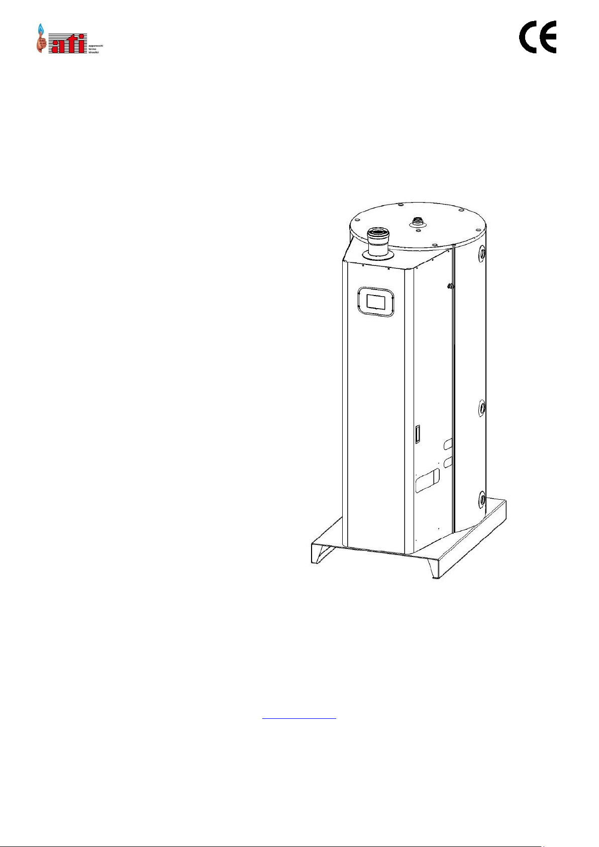
CONDENSING GAS-FIRED STORAGE
WATER HEATER.
WHC400
WHC500
WHC700
WHC900
ENG - Manual of installation, use and
maintenance.
Read and follow these instructions before installing the unit.
Always keep on hand this manual during any servicing intervention.
This manual is also available in the electronic format and can be downloaded from the website
www.atimariani.it
Jan-19
ATI DI MARIANI SRL - Via E. Mattei, 461 – Zona Industriale No. 4 Torre del Moro - 47522 Cesena (FC) - Italy
Tel .: +39 0547 609711 - Fax: +39 0547 609724 - Web: www.atimariani.it - Email: info@atimariani.it
VAT NR. IT 00281090407 - REA 143693
Page 2

ENG - Manual of installation, use and maintenance.
210-0352_libretto_WHC_ATI_eng.docx
2
Jan-19
INDEX
1. GENERAL WARNINGS ................................................................................................................................................................. 3
2. TRANSPORT, STORING AND RECYCLING .................................................................................................................................... 4
3. CORRECT DISPOSAL OF THE PRODUCT....................................................................................................................................... 4
4. CONTENT, WEIGHT AND PACKAGING DIMENSIONS .................................................................................................................. 5
5. APPLIANCE CATEGORIES ............................................................................................................................................................ 5
6. TECHNICAL SPECIFICATIONS ...................................................................................................................................................... 6
7. COUNTRIES OF DESTINATION AND GAS CATEGORIES................................................................................................................ 6
8. APPLIANCE DIMENSIONS AND FEATURES .................................................................................................................................. 7
9. THE INSIDE OF THE APPLIANCE .................................................................................................................................................. 8
10. FUNCTIONAL AND STRUCTURAL DESCRIPTION ..................................................................................................................... 9
11. COMPONENTS OF THE BOILER ............................................................................................................................................ 10
12. CONTROL PANEL DISPLAY .................................................................................................................................................... 11
13. SAFETY AND INSTALLATION LOCAL REGULATIONS .............................................................................................................. 11
14. INSTALLATION ...................................................................................................................................................................... 13
15. POSITIONING THE APPLIANCE ............................................................................................................................................. 13
16. FLUE SYSTEM ....................................................................................................................................................................... 14
17. WATER CONNECTION .......................................................................................................................................................... 16
18. GAS CONNECTION ................................................................................................................................................................ 17
19. ELECTRICAL CONNECTIONS .................................................................................................................................................. 17
20. STARTING AND TEMPERATURE ADJUSTMENT ..................................................................................................................... 18
21. GAS SETTING AND CHANGING OF GAS TYPE ....................................................................................................................... 20
22. MENU PARAMETERS AND DESCRIPTION ............................................................................................................................. 23
23. ANTILEGIONELLA FUNCTION ............................................................................................................................................... 25
24. ELECTRONIC BOARD AND WIRING ....................................................................................................................................... 26
25. OTHER SYSTEM FEATURES ................................................................................................................................................... 29
26. FAULTS ................................................................................................................................................................................. 29
27. SAFETY ANOMALIES ............................................................................................................................................................. 29
28. PROBES FAULTS ................................................................................................................................................................... 34
29. FAN FAULTS ......................................................................................................................................................................... 36
30. FAULTS FLOW....................................................................................................................................................................... 38
31. SERVICING THE HEAT EXCHANGER ...................................................................................................................................... 39
32. PERIODIC MAINTENANCE .................................................................................................................................................... 39
33. WARRANTY VALIDATION ..................................................................................................................................................... 39
Page 3

ENG - Manual of installation, use and maintenance.
210-0352_libretto_WHC_ATI_eng.docx
3
Jan-19
1. GENERAL WARNINGS
THIS BOOKLET IS AN INTEGRAL AND ESSENTIAL PART OF THE APPLIANCE AND MUST BE KEPT WITH
CARE NEXT TO IT FOR ANY FUTURE REFERENCE. IT CONTAINS IMPORTANT INFORMATION
REGARDING SAFETY, INSTALLATION, OPERATION AND MAINTENANCE.
THE APPLIANCE IS DESIGNED FOR HOT WATER PRODUCTION ONLY: ANY OTHER USE OF IT IS
UNSUITABLE AND DANGEROUS.
THE APPLIANCE SHOULD NOT BE INSTALLED IN DAMP ROOMS AND HAS TO BE PRESERVED BY
SPRINKLINGS OF WATER OR OTHER LIQUIDS, TO AVOID DAMAGES TO ELECTRICAL AND THERMAL
DEVICES.
A QUALIFIED PERSON, WHO IS RESPONSIBLE FOR THE IMPLEMENTATION OF THE EXISTING SAFETY
STANDARDS, MUST PERFORM THE INSTALLATION. AN IMPROPER INSTALLATION, CAUSED BY THE
NON-OBSERVANCE OF THE MANUFACTURER’S INSTRUCTIONS, MAY CAUSE INJURY TO PERSONS,
ANIMALS OR DAMAGES, FOR WHICH THE MANUFACTURER DECLINES ALL RESPONSIBILITY.
KEEP ALL PACKAGING MATERIAL (PLASTIC BAGS, POLYSTYRENE, WOOD, CLIPS, ETC.) OUT OF REACH
OF CHILDREN AS IT MAY PRESENT A POTENTIAL HAZARD.
THE APPLIANCE IS NOT INTENDED FOR USE BY CHILDREN AGED LESS THAN 8 YEARS AND BY
PERSONS WITH REDUCED PHYSICAL, SENSORY OR MENTAL CAPACITIES, LACK OF EXPERIENCE OR
KNOWLEDGE, UNLESS THEY HAVE BEEN GIVEN SUPERVISION OR INSTRUCTIONS CONCERNING THE
USE OF THE APPLIANCE BY A PERSON RESPONSIBLE FOR THEIR SAFETY.
CHILDREN SHALL NOT PLAY WITH THE APPLIANCE.
CLEANING AND MAINTENANCE, INTENDED TO BE CARRIED OUT BY THE USER, SHALL NOT BE MADE
BY CHILDREN WITHOUT SUPERVISION.
IF THE APPLIANCE IS SOLD OR TRANSFERRED TO ANOTHER OWNER, MAKE SURE THAT THIS
BOOKLET STAYS WITH THE APPLIANCE, SO THE NEW OWNER AND / OR INSTALLER CAN CONSULT IT.
DO NOT PUT ANYTHING ON THE TOP OF THE APPLIANCE. IN ORDER TO AVOID DAMAGES CAUSED
BY FROST, DRAIN THE TANK COMPLETELY, IN THE EVENT THE APPLIANCE IS LEFT UNUSED FOR A
LONG PERIOD IN A NON HEATED ROOM. THE MANUFACTURER IS NOT RESPONSIBLE FOR FAULTY
OPERATIONS OR BROKEN PARTS CAUSED BY FROST AND FOR WATER LEAKAGE FROM THE PLANT.
TO GET THE BEST PERFORMACE AND THE WARRANTY VALIDATION, WE RECOMMEND TO FOLLOW
THE INSTRUCTIONS HERE BELOW AND TO USE ONLY ORIGINAL SPARE PARTS AND KITS PROVIDED
BY THE MANUFACTURER.
MORE APPLIANCES IN THE SAME ROOM, FOR A TOTAL THERMAL CAPACITY HIGHER THAN 35 KW,
ARE A HEAT STATION AND ARE SUBJECT TO THE PROVISION OF THE FIREMEN CIRCULAR NO. 68.
IT IS STRICTLY FORBIDDEN TO TAMPER ANY DEVICE FACTORY SET AND SEALED BY THE
MANUFACTURER.
Page 4
ENG - Manual of installation, use and maintenance.
210-0352_libretto_WHC_ATI_eng.docx
4
Jan-19
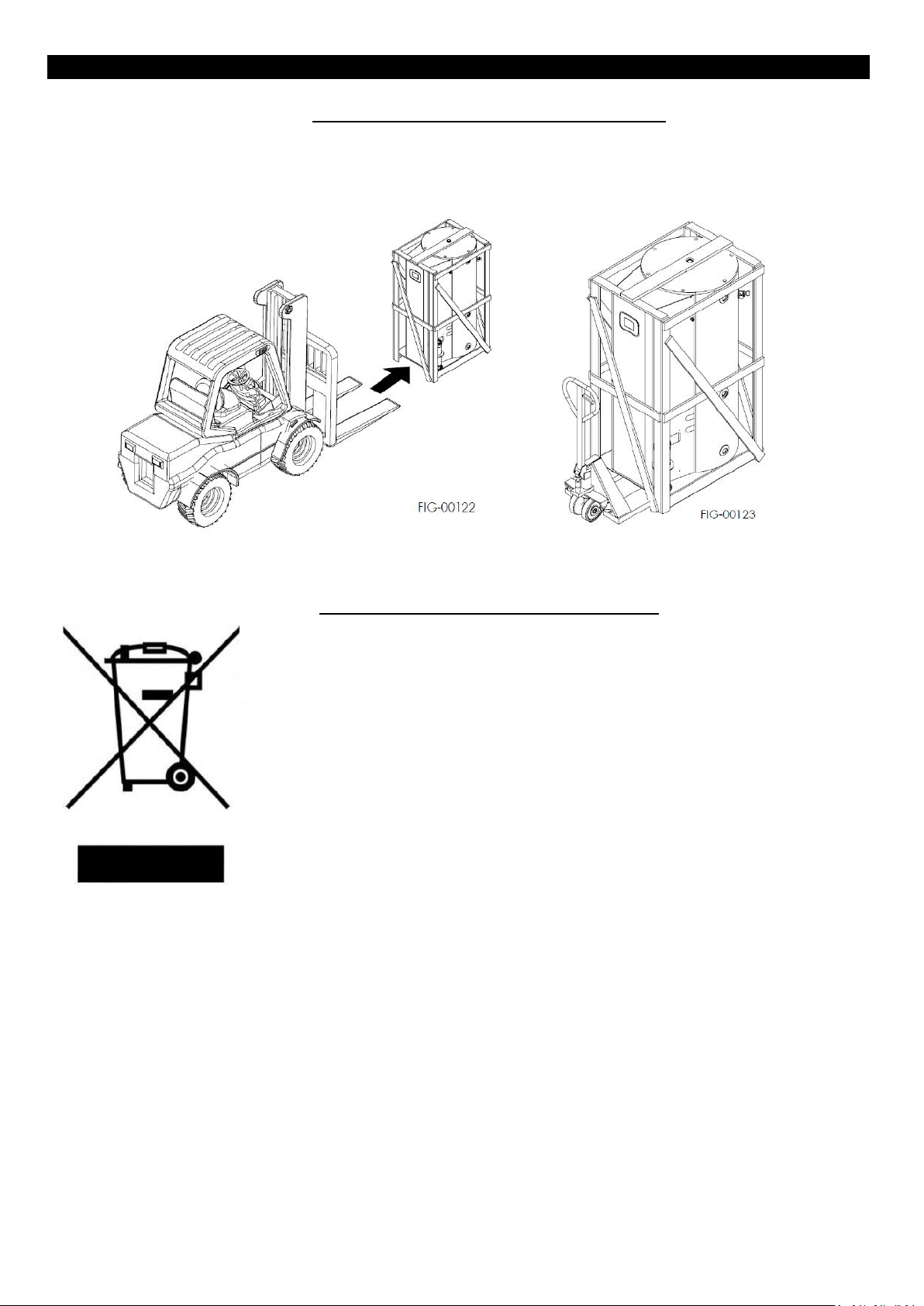
2. TRANSPORT, STORING AND RECYCLING
• The appliance must be transported and stored under cover and protected from frost.
• The appliance must not be handled and / or laid horizontally: it can be transported only in a vertical position.
• Handle the unit by means of a forklift or a manual pallet truck. Enter the parallel arms of the forklift in the lower part of the
appliance, as shown in the picture below.
• Remove the packaging by undoing the 4 screws at the bottom corners of the appliance, then pull upwards the packaging,
being careful not to damage the appliance.
3. CORRECT DISPOSAL OF THE PRODUCT
The symbol shown on the equipment indicates that waste must be disposed of in “separate
collection” and so the product must not be disposed of together with urban waste. The user
must take the product to special “separate waste collection centres” provided by local
government, or deliver it to the retailer against the purchase of a new product. Separate
collection of waste and subsequent treatment, recycling and disposal operations promotes the
production of equipment with recycled materials and limits negative effects of waste. Illegal
disposal of the product leads to the enforcement of administrative penalties.
Page 5
ENG - Manual of installation, use and maintenance.
210-0352_libretto_WHC_ATI_eng.docx
5
Jan-19
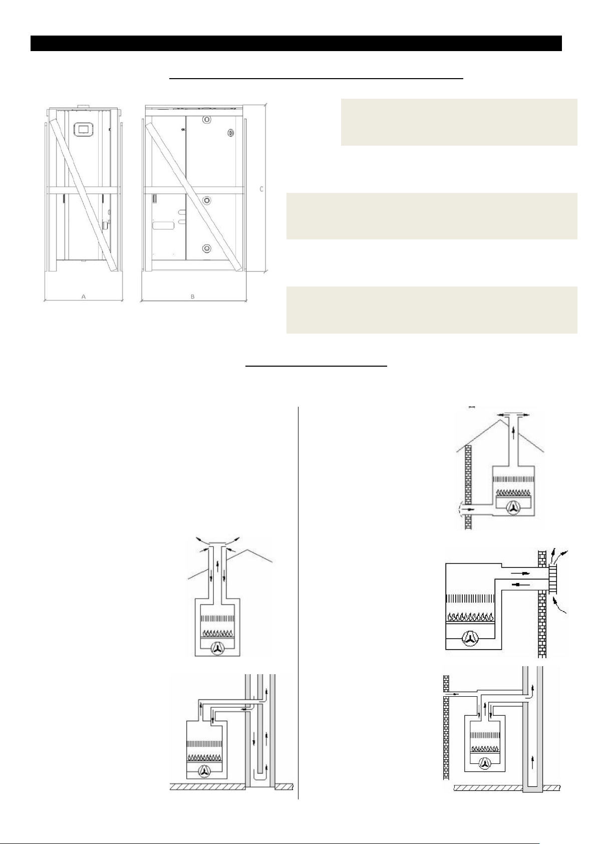
Dimensions in mm - Weight in kilograms: Kg
WHC400
WHC500
WHC700
WHC900
A
820
820
1030
1030
B
1100
1100
1300
1300
C
1740
2100
1800
2170
Weight
with
packaging
203
229
259
297
C63 appliance connected to an air intake and flue outlet
approved system and sold separately; the fan is upstream of
the heat exchanger.
C53 appliance connected to
two points having a different
pressure; the fan is upstream
of the heat exchanger.
C33 appliance connected to
coaxial or twin pipe flue
system so close to have the
same vertical wind conditions
(roof) with fan upstream of
the heat exchanger.
C13 appliance connected to
coaxial or twin pipe flue
system so close to have the
same wind conditions
(horizontally through the
wall) with fan upstream of
the heat exchanger.
C43 appliance connected to
coaxial or twin pipe flue
system so close to have the
same wind conditions, which
intakes air from the chimney
and with fan upstream of the
heat exchanger.
C83 appliance connected to
twin pipe flue system with air
intake from the outside and
flue outlet through the
chimney; the fan is upstream
of the heat exchanger.
4. CONTENT, WEIGHT AND PACKAGING DIMENSIONS
The appliance is delivered packaged in a wooden cage with appropriate protection. See table below for size.
5. APPLIANCE CATEGORIES
These appliances are classified as: "Condensing gas fired storage water heaters".
Gas Categories: I2H, I3P I2L and derived second categories
TYPE C Appliance classes (EN 483) (see table):
Page 6

ENG - Manual of installation, use and maintenance.
210-0352_libretto_WHC_ATI_eng.docx
6
Jan-19
WHC400
WHC500
WHC700
WHC900
Classe efficienza sanitaria - efficiency class
A B B A
Profilo di carico - load profile
XXL
XXL
XXL
XXL
Capacita’ nominale serbatoio - tank nominal capacity
l
395
500
700
856
Efficienza – efficiency
%
84
78
78
116
Portata termica nominale Q - nominal calorific flow rate QN
kW
25
25
25
25
Portata termica minima Q - minimum calorific flow rate Qm
KW 5 5 5 5
Potenza termica nominale P - nominal power output PN
KW
24,5
24,5
24,5
24,5
Potenza termica minima P - minimum power output Pm
KW
8,3
8,3
8,3
8,3
Consumo gas - gas consumption
m3/h
2,7
2,7
2,7
2,7
Temperatura fumi – flue gas temperature
°C
68
68
68
68
Valore di emissione di NOx - NOx emission value
mg/kWh
53
53
53
53
Pressione max acqua - max water pressure
kPa (bar)
600 (6)
600 (6)
600 (6)
600 (6)
η combustione - Η combustion
%
98
98
98
98
η acqua - H water
%
99
102
100
100
Prelievo continuo Δ 25°c - Δ 25°C water spillage
l/h
841
841
841
841
Grado di protezione – protection level for electrical
appliance
IP
21
21
21
21
Potenza elettrica nominale - nominal electric power
W
51
51
51
51
Caratteristiche elettriche - Electrical characteristics
V/Hz
230V ~ 50Hz
230V ~ 50Hz
230V ~ 50Hz
230V ~ 50Hz
Country (EN ISO 3166-1):
Category:
gas type / pressure (EN 437):
AL
I2H, I3P II 2H3P
G20 - 20 mbar; G31 - 37 mbar
AT
I2H
G20 - 20 mbar
BE
I2H, I3P II 2H3P
G20 - 20 mbar; G31 - 37 mbar
BG
I2H, I3P II 2H3P
G20 - 20 mbar; G31 - 37 mbar
CH
I2H, I3P II 2H3P
G20 - 20 mbar; G31 - 37 mbar
CY
I2H
G20 - 20 mbar
CZ
I2H, I3P II 2H3P
G20 - 20 mbar; G31 - 37 mbar
DE
I2E
G20 - 20 mbar
DK
I2H
G20 - 20 mbar
EE
I2H
G20 - 20 mbar
ES
I2H, I3P II 2H3P
G20 - 20 mbar; G31 - 37 mbar
FI
I2H
G20 - 20 mbar
FR
I2H, I2Er, I2Esi, I3P II 2H3P, II2Esi3P
G20 - 20 mbar; G25 - 25 mbar; G31 - 37 mbar
GB
I2H, I3P II 2H3P
G20 - 20 mbar; G31 - 37 mbar
GR
I2H, I3P II 2H3P
G20 - 20 mbar; G31 - 37 mbar
HU
I2H, I3P
G20 - 25 mbar; G31 - 37 mbar
IE
I2H, I3P II 2H3P
G20 - 20 mbar; G31 - 37 mbar
IT
I2H, I3P II 2H3P
G20 - 20 mbar; G31 - 37 mbar
LT
I2H, I3P II 2H3P
G20 - 20 mbar; G31 - 37 mbar
LU
I2H
G20 - 20 mbar
LV
I2H
G20 - 20 mbar
MK
I2H, I3P II 2H3P
G20 - 20 mbar; G31 - 37 mbar
MT
I2H
G20 - 20 mbar
NL
I2L, I3P II2L3P
G25 - 25 mbar; G31 - 37 mbar
NO
I2H
G20 - 20 mbar
PL
I2E; I3P II2E3P
G20 - 20 mbar; G31 - 37 mbar
PT
I2H, I3P II 2H3P
G20 - 20 mbar; G31 - 37 mbar
RO
I2H, I2E; I3P II 2H3P
G20 - 20 mbar; G31 - 37 mbar
SE
I2H
G20 - 20 mbar
SI
I2H, I3P II 2H3P
G20 - 20 mbar; G31 - 37 mbar
SK
I2H, I3P II 2H3P
G20 - 20 mbar; G31 - 37 mbar
TR
I2H
G20 - 20 mbar
6. TECHNICAL SPECIFICATIONS
7. COUNTRIES OF DESTINATION AND GAS CATEGORIES
Page 7
ENG - Manual of installation, use and maintenance.
210-0352_libretto_WHC_ATI_eng.docx
7
Jan-19
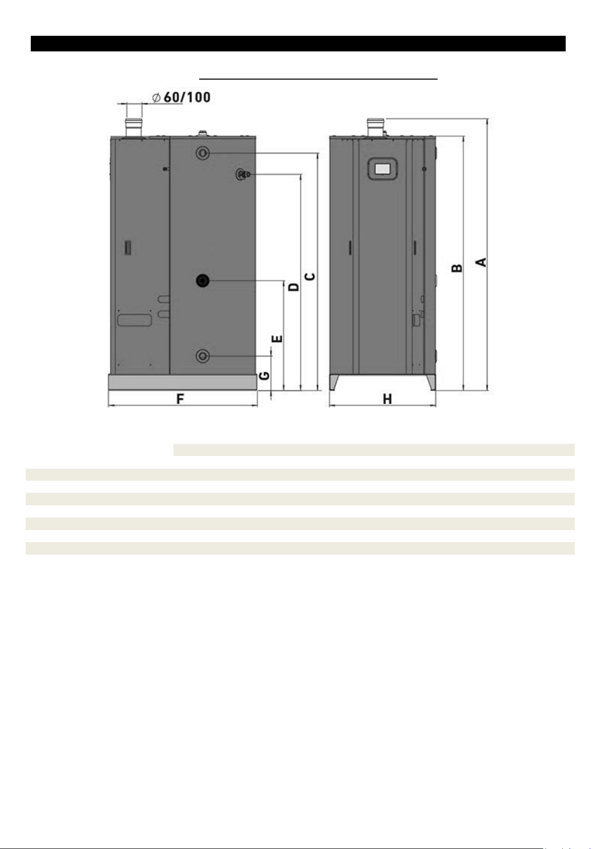
WHC400
WHC500
WHC700
WHC900
A FLUES IN & OUT
1810
1810
1810
1810
B HEIGHT
1699
2049
1754
2114
C HOT WATER OUTLET G 1-1/4”
1585
1936
1641
1999
D SAFETY VALVE
1443
1443
1462
1462
E RETURN G 1”
733
733
752
752
F DEPTH
990
990
1190
1190
G COLD WATER INLET G 1-1/4”
229
229
205
205
H WIDTH
710
710
920
920
8. APPLIANCE DIMENSIONS AND FEATURES
Dimensions in millimeters: mm
Page 8
ENG - Manual of installation, use and maintenance.
210-0352_libretto_WHC_ATI_eng.docx
8
Jan-19
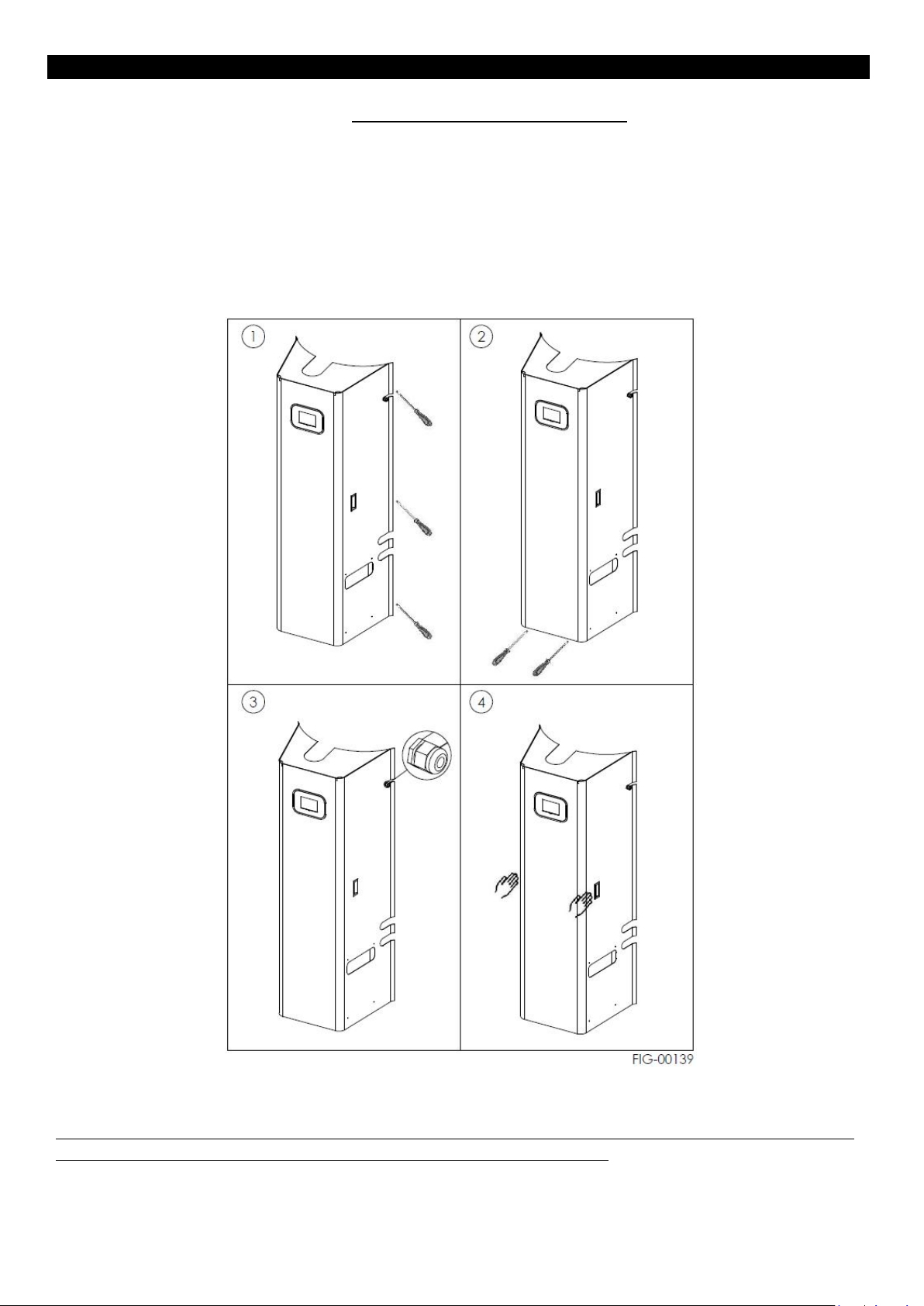
9. THE INSIDE OF THE APPLIANCE
The following instructions will show the internal components of the heating boiler, their configuration and maintenance.
Remove the frontal casing of the appliance to carry out these interventions.
1. remove the screws from both the left and right side, by means of a common screwdriver (not supplied);
2. remove the screws from the lower part of the appliance;
3. paying attention to the upper gland, unscrew the nut on the opposite side of the sheet, so to push the cable out of the
sheet slot, then leave the cable free;
4. it is now possible to remove the whole front bonnet by means of the handles on both sides of the appliance.
To reassemble the bonnet, follow the instructions in reverse.
PAY ATTENTION TO THE STEEL RIMS, BECAUSE THEY MAY BE SHARP: THE USE OF PROTECTIVE EQUIPMENT IS RECOMMENDED.
THE MANUFACTURER DOES NOT ASSUME ANY RESPONSIBILITY FOR POSSIBLE INJURIES.
Page 9
ENG - Manual of installation, use and maintenance.
210-0352_libretto_WHC_ATI_eng.docx
9
Jan-19
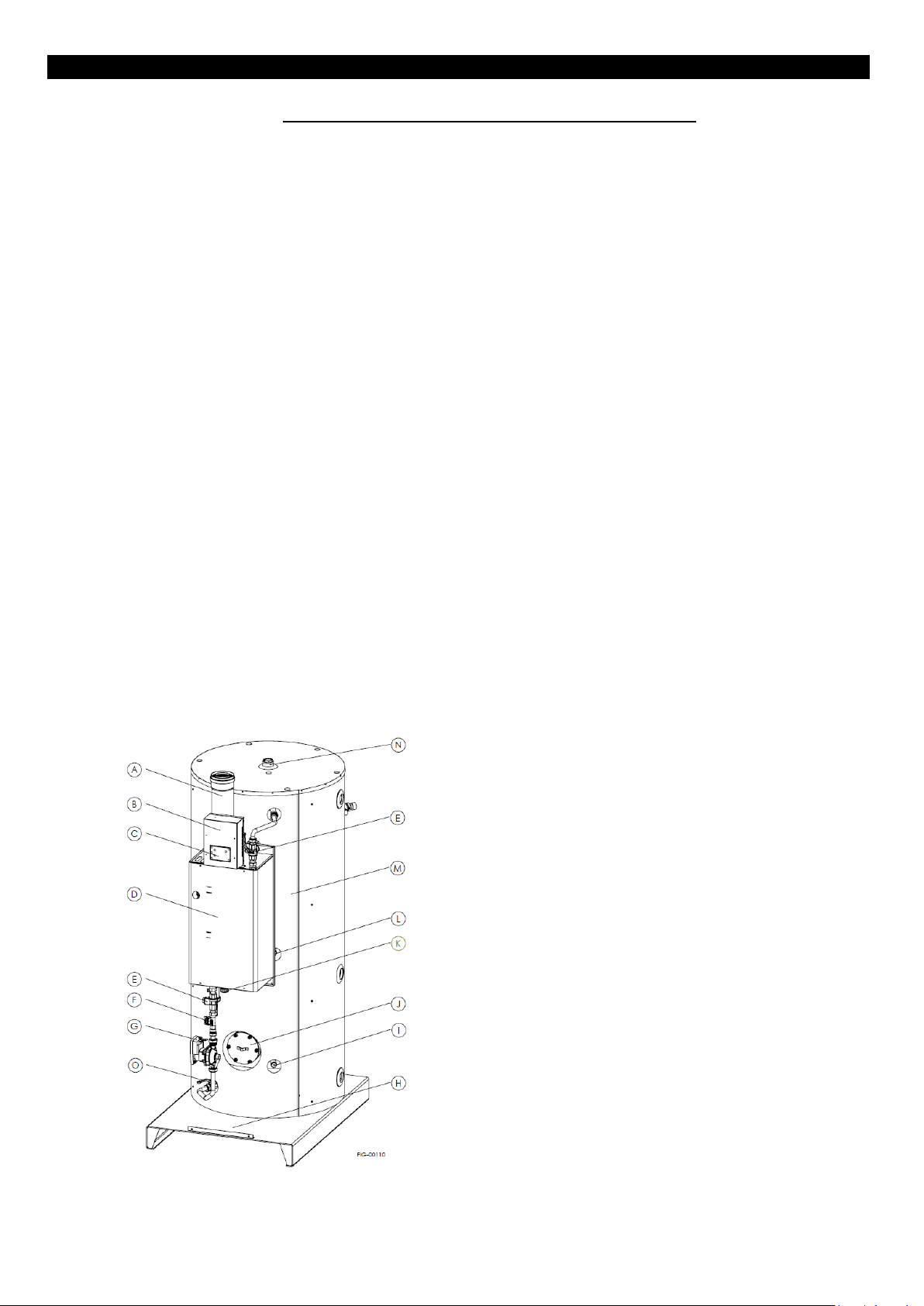
A. AIR IN & OUT
B. CONTROL BOX CASING
C. CONTROL PANEL DISPLAY
D. HEATING BOILER
E. 3-WAY VALVE
F. FLOWMETER
G. WATER PUMP
H. BASEMENT – HANDLING POINT
I. LOWER PROBE
J. INSPECTION FLANGE WITH ANODE
K. CONDENSATE DRAIN
L. MIDDLE PROBE
M. STORAGE TANK
N. UPPER ANODE
O. BALL VALVE
10. FUNCTIONAL AND STRUCTURAL DESCRIPTION
The purpose of this appliance is to allow the heat exchange between the combustion products of the premix burner and the
water stored in the tank through a heat exchanger that is in contact with the burner.
The combustion is completely sealed with respect to the place where the appliance is installed, taking in the air required for
combustion from the outside and discharging the combustion products always outside.
The sealed combustion chamber is placed in the front part of the appliance, inside the casing.
A siphon, which grants the condensate drain, is placed at the bottom of the appliance.
TANK
It is built with a sturdy sheet and grants a remarkable resistance to pressure. It is also subject to an internal glass lining
treatment. A Ø120 flange allows the inspection and cleaning of its internal surface.
HEATING BOILER
It is placed in the front part of the appliance and is composed of: burner, heat exchanger, gas valve, premix fan. The chamber is
airtight with respect to the place where the appliance is located.
3-WAY VALVE
It is used to allow an accurate maintenance of the internal heat exchanger.
WATER PUMP AND FLOWMETER
They are located under the boiler. The water pump collects the water from the tank and pushes it vertically towards the heat
exchanger. The flowmeter senses the flow rate values and transmits them to the control board.
FLUE KITS (it is compulsory to install the kit provided by the appliance manufacturer)
To be chosen amongst those available, according to the installation requirements. It allows the connection of the combustion
chamber with the outside, bringing the combustion air to the burner and discharging flues.
MAGNESIUM ANODE
The appliance is factory equipped with two magnesium anodes in order to protect the device from galvanic currents that can
corrode the interior surface of the appliance. One anode is installed on the inspection flange, the other one is located in the
upper part of the appliance.
Page 10
ENG - Manual of installation, use and maintenance.
210-0352_libretto_WHC_ATI_eng.docx
10
Jan-19
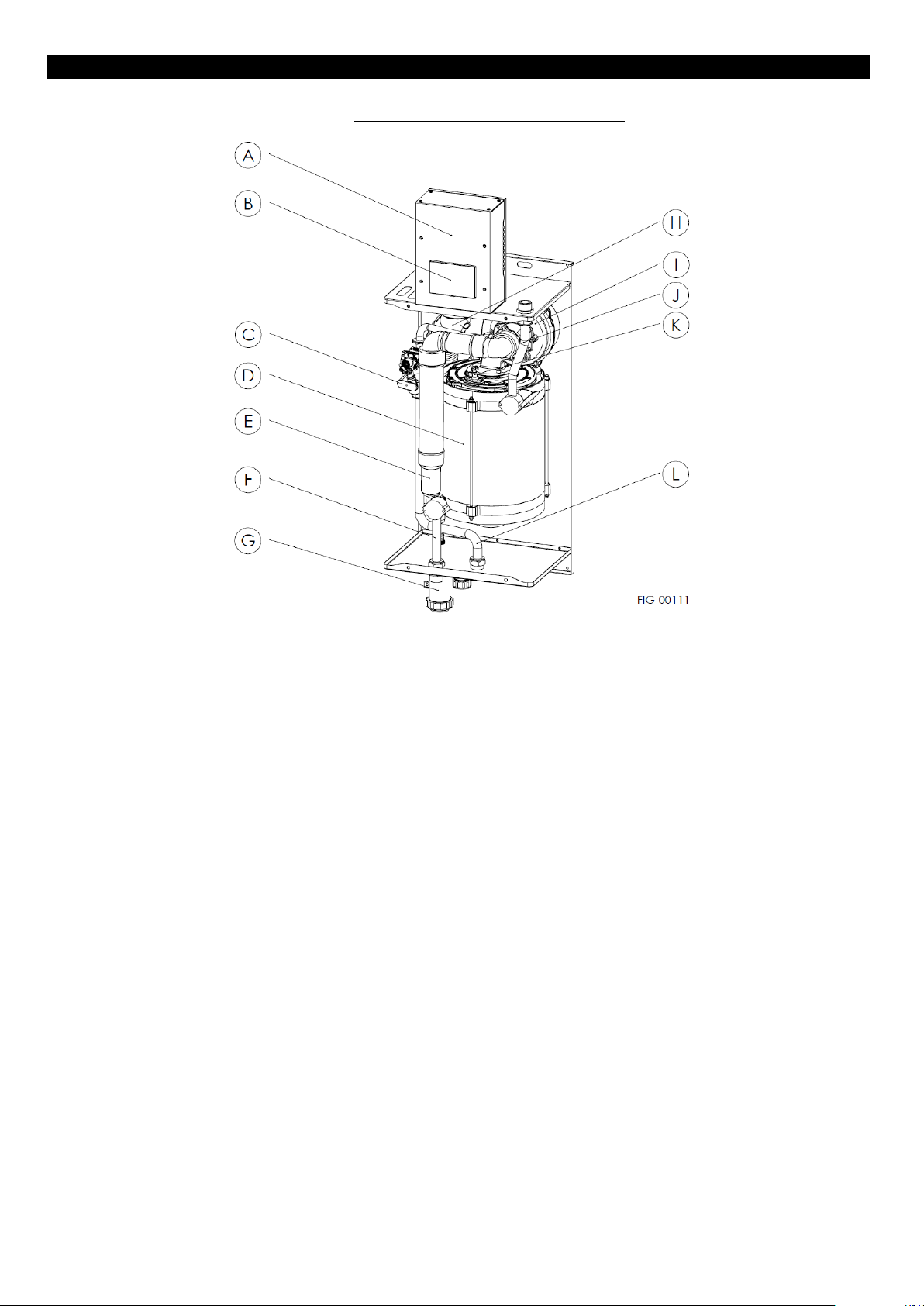
11. COMPONENTS OF THE BOILER
A. CONTROL BOX CASING
Protective cover of the electronic control box and earthing
point.
B. CONTROL PANEL DISPLAY
It is used by the operator to ensure the full control of the
appliance software.
C. GAS VALVE
Located on the left side of the heat exchanger, it adjusts
the inlet gas flow to the premix fan.
D. HEAT EXCHANGER
It consists of a stainless steel coil and allows the heat
exchange between the combustion heat and the sanitary
hot water of the boiler.
E. AIR CHANNEL
It is used for channeling the incoming air to the injector
holder. The air intake is done through the coaxial outer
tube.
F. WATER INLET
Copper-brass pipe for the water extraction from the boiler.
G. CONDENSATE DRAIN
A siphon is located under the boiler: it collects condensate.
It is necessary to discharge condensate by means of a
flexible tube and to collect it in a system specially conceived
for this purpose.
H. FLUE OUTLET
Flue pipe. A condensate trap is placed at its bottom.
I. FAN
The fan is used to mix air and gas before the burner.
J. WATER OUTLET
Copper-brass pipe for the hot water outlet from the heat
exchanger.
K. ELECTRODES
Two electrodes (an ingnition and a detection one) are
located in the upper part of the heat exchanger.
L. GAS INLET PIPE
copper-brass pipe for the gas inlet into the appliance.
Page 11
ENG - Manual of installation, use and maintenance.
210-0352_libretto_WHC_ATI_eng.docx
11
Jan-19
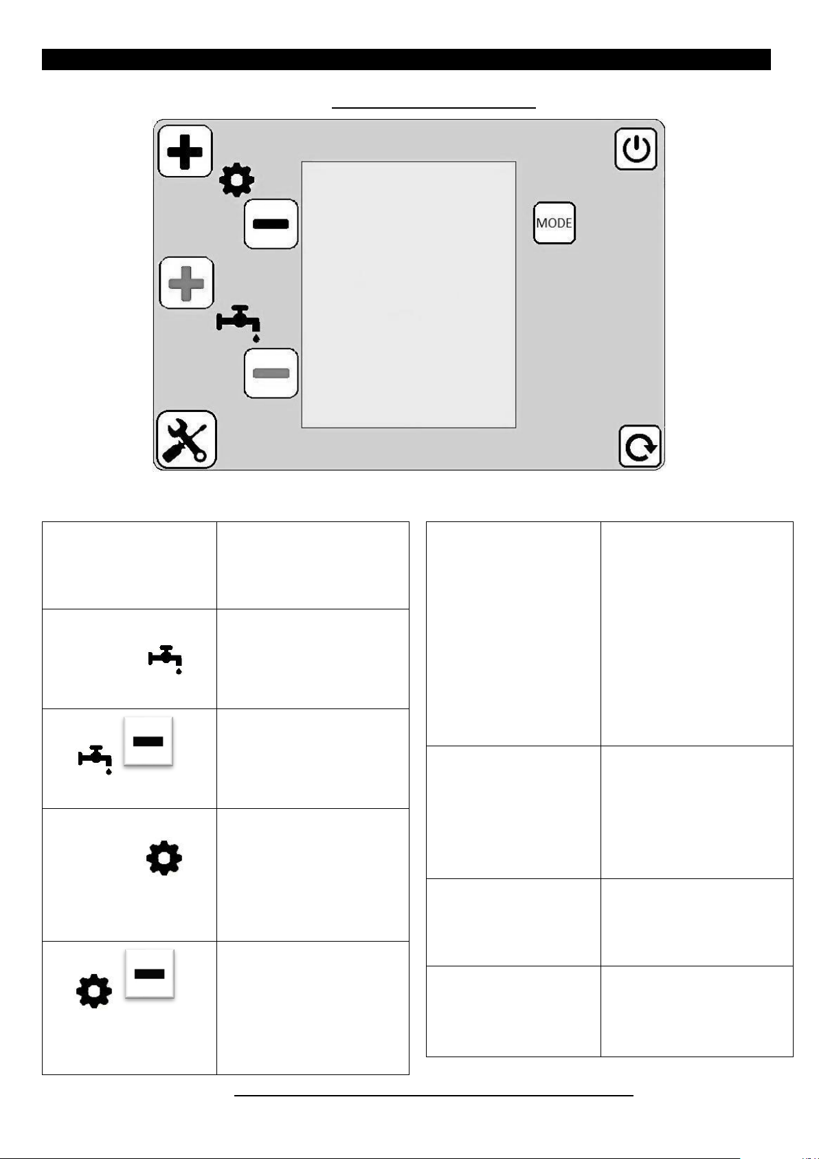
On / Off (press for 2 seconds)
+ Flow set-point
+ 2nd password digit
+ Parameter Index
- Flow set-point
- 2nd password digit
- Parameter Index
+ 1st password digit
+ Parameter value
+ Information
Maximum output operation
- 1st password Digit
- Parameter value
- Information
Minimum output operation
Exit from the information
menu
Exit from the password menu
Exit from the parameter menu
Exit from the chimney sweep
mode
Starting high chimney sweeper
(press for 5 seconds)
Information menu
+ Information
Password confirmation
parameters storing
boiler release
+
Login Menu / Parameters
Password
12. CONTROL PANEL DISPLAY
13. SAFETY AND INSTALLATION LOCAL REGULATIONS
Page 12

ENG - Manual of installation, use and maintenance.
210-0352_libretto_WHC_ATI_eng.docx
12
Jan-19
LOCAL REGULATIONS
The installation must be in accordance with the local regulations established by:
Fire fighters
Gas Supply Company
Power Supply Company
Hygiene and Health Office
SAFETY REGULATIONS
Do not perform any cleaning or maintenance work without having turned off the water heater and cut-off the power.
Operating the water heater with disassembled protections of the electrical parts or with excluded safety devices is
absolutely forbidden. Removing or tampering the safety devices is absolutely forbidden.
In case of failure and / or malfunction, switch off the appliance, close the gas cock and do not try to repair it, but contact an
authorized service centre.
In case of fire, use powder fire extinguishers only, do not direct jets of water directly against the heater as this may cause
short circuits.
Use suitable manual or electrical tools and / or equipment: make sure that they are not worn out and that they are used
properly.
Make sure that ladders and / or rolling ladders are firmly positioned, that they are appropriate and that the steps are intact
and not slippery, that they are not moved while someone is climbing them and that someone provides supervision at all
times.
INSTALLATION INSTRUCTIONS
During installation or servicing carried out at a certain height (generally with a difference in height of more than 2 meters),
use rolling towers compliant with legal standards and make sure that the space below is free because tools and objects may
fall.
Make sure that, while installing and servicing the appliance, the workplace has suitable hygiene conditions in terms of
lighting, ventilation and solidity of the structures.
Wear individual protective clothing and equipment while installing and servicing the appliance.
Do not take any action without a prior check of the absence of gas leaks by using a special detector.
The installer must be qualified in the installation of heating equipment according to the law n. 46 of 05/05/1990 and, at the
end, he has to issue the CONFORMITY DECLARATION to the customer.
The appliance should be connected to a sanitary hot water distribution network that must be compatible with its
performance and power levels. Make sure that the installation site and any systems to which the appliance must be connect
comply with the regulations in force.
Being a C-type unit, the appliance can be installed in any kind of place, without any restriction to its ventilation condition
and volume.
Before any installation, maintenance or repairing intervention, cut off the power supply to the unit. Protect all connection
pipes and wires in order to prevent them from being damaged.
The device has to be installed on the floor, leaving a suitable distance from the side walls to allow the gas and water
connections, as well as any possible maintenance intervention. Furthermore, the appliance must be installed on a solid wellfinished flat floor, that is not subject to vibration.
Reseal the openings used to make the readings of CO
2
values at the maximum and minimum power.
All operations inside the appliance must be performed with the necessary caution in order to avoid abrupt contact with
sharp parts.
Do not take any action without a prior check of the absence of an open flame or ignition sources.
In case you detect a smell of burning or smoke coming from the appliance or a strong smell of gas, disconnect the appliance
from the electrical supply, turn off the main gas valve, open all windows and contact the nearest authorized assistance
service.
IN ANY SITUATION, COMMON SENSE IS THE BEST SAFETY AGAINST ANY DAMAGE AND / OR INJURY.
Page 13

ENG - Manual of installation, use and maintenance.
210-0352_libretto_WHC_ATI_eng.docx
13
Jan-19
14. INSTALLATION
OPERATION TO BE CARRIED OUT BY A QUALIFIED PERSON ONLY
Warning! The installation of the residential ventilation system must be performed by a qualified person only, in order to avoid
damage or injury.
Before installing the appliance, check that the nominal supply voltage is 220 / 240V - 50Hz.
Make sure that the electrical system is suitable to supply, in addition to the operating power required by the unit, also
the necessary power for powering the appliances and equipment already in use.
perform the electrical connections in accordance with national laws and regulations.
Foresee an omnipolar switch with a minimum contacts distance of 3.5 mm upstream the unit.
The installation of the device is divided into 5 distinct phases, which are listed below, and which have to be followed respecting
the order.
1. positioning the appliance
2. Flue system
3. Water supply connections
4. Gas supply connection
5. Electrical supply connections
The appliance needs to be earthed. Check that the electrical supply cable is in perfect condition. Under no circumstances repair
the damaged cable with insulating tape or clips. If the power cord is damaged, it must be replaced by service person or by a
similarly qualified person in order to avoid any hazard.
Improper installation may harm people, animals and possessions: the manufacturer shall not be held responsible for any
damage caused as a result.
15. POSITIONING THE APPLIANCE
The location of the appliance must be chosen according to the maximum length allowed for each type of flue system, gas and
electrical connection. The appliance is designed to have water, gas and electrical connections on the right side of the appliance,
whereas the flue gas outlet is on the top of the appliance. It is recommended to place the heater in such a way as to facilitate
the installation and maintenance operations.
The appliance, being a C-type unit, can be installed in any kind of place, without any restriction to its ventilation condition and
volume.
The minimum acceptable clearances are shown below.
The front and right side of the appliance must be easily accessible, in order to facilitate proper installation and periodic
maintenance.
To prevent possible infiltration of water during a thunderstorm, we recommend a slight downward slope of the flue and air duct.
IMPORTANT: INSTALL IN ACCORDANCE WITH THE REQUIREMENTS OF NATIONAL INSTALLATION REGULATIONS
Page 14

ENG - Manual of installation, use and maintenance.
210-0352_libretto_WHC_ATI_eng.docx
14
Jan-19
FLUE KIT
DESCRIPTION
AKIT11
Ø60 / 100 horizontal
Length: 1.85m
Height: 0.2m
Minimum length: 1.5m
Maximum length: 10m
AKIT12
Ø80 / 80 horizontal
Length: 2.1m
Height: 0.3m
Minimum length: 1m + 1m
Maximum length: 30m + 30m
AKIT13
Ø80 / 125 horizontal
Length: 1,4m
Height 0.3m
Minimum length: 1.5m
Maximum length: 26m
FLUE KIT
DESCRIPTION
REF.
AKIT11
Ø60 / 100 horizontal
Ø60 / 100 L = 500 coaxial extension
AKIT11-01
Ø60 / 100 L = 1000 coaxial extension
AKIT11-02
Ø60 / 100 L = 2000 Coaxial extension
AKIT11-03
Ø60 / 100 45° Coaxial bend
AKIT11-04
Ø60 / 100 90° Coaxial bend
AKIT11-05
AKIT12
Ø80 / 80 twin pipe
horizontal
Ø80 L = 250 Extension
AKIT12-01
Ø80 L = 500 Extension
AKIT12-02
Ø80 L = 1000 Extension
AKIT12-03
Ø80 L = 2000 Extension
AKIT12-04
Ø80 45° bend
AKIT12-05
Ø80 90° bend
AKIT12-06
AKIT13
Ø80 / 125 horizontal
Ø80 / 125 L = 500 coaxial extension
AKIT13-01
Ø80 / 125 L = 1000 coaxial extension
AKIT13-02
Ø80 / 125 L = 2000 coaxial extension
AKIT13-03
Ø80 / 125 45°Coaxial bend
AKIT13-04
Ø80 / 125 90°Coaxial bend
AKIT13-05
16. FLUE SYSTEM
The appliance is a watertight premixed condensing boiler with fan upstream of the combustion chamber, equipped with a
storage tank on the back. The low temperature of the exhaust flues allows the use of plastic flue systems. The installation of the
flue systems must comply with local regulations in force.
The installation must comply also with municipal, provincial or sectoral regulations. Conveying the flue gases of more boilers
within the same flue duct is not allowed: each boiler must have its own separate exhaust duct.
The water heater is factory supplied without flue kit. All the flue kits available for this unit are listed in the following chart. Use
only the original kits (to be purchased separately depending on the type of exhaust system chosen) provided by the
manufacturer.
It is necessary to purchase special extensions (see the chart here below) to increase the flue length. The maximum allowed
extension is shown in the chart above. For each additional 90° elbow 1 meter must be subtracted from the total flue length. The
choice of a flue option rather than the other has to take into account local regulations, as well as technical considerations.
The mechanical stability of the air / flue duct has to be granted
Page 15

ENG - Manual of installation, use and maintenance.
210-0352_libretto_WHC_ATI_eng.docx
15
Jan-19
The hole for passing the exhaust and the air intake pipe through the wall should not be blocked and the flue pipe must be free to
slide through the hole in such a way that it can subsequently be detached. You can use the wall covers supplied with the flue kits
to cover the empty space of the hole.
IMPORTANT: LEAVE A CLEARANCE OF NO LESS THAN 60 CM ABOVE THE APPLIANCE TO ALLOW ANY MAINTENANCE TO THE TOP
OF THE UNIT.
CONNECTION TO THE BOILER
The unit is factory supplied with a Ø60 / 100 polypropylene flue connection, provided with air and flue sampling.
The flue connection is not installed: it is packed together with the unit and positioned at the bottom of it, ready for installation.
IMPORTANT: MAKE SURE YOU HAVE THE SAMPLING PLUGS FACING THE LEFT SIDE OF THE UNIT, TO ENSURE A PRACTICAL USE
OF THEM. A WRONG POSITIONING CAN MAKE THE FLUE ANALYSYS DIFFICULT.
Page 16

ENG - Manual of installation, use and maintenance.
210-0352_libretto_WHC_ATI_eng.docx
16
Jan-19
17. WATER CONNECTION
The appliance will last longer if the following parameters are met (as provided by the D. LGS. nr 31 February 2nd 2001, which is
an implementation of EC Directive 98/83/CE on the quality of water intended for human consumption):
1. Total hardness: between 10 ° F and 25 ° F
2. pH: between 6 and 8
3. Conductivity: max. 2500 µS / cm
The appliance is protected against corrosion by a magnesium anode that must be replaced at least once every 12 months
otherwise the warranty will be invalidated.
IMPORTANT: IF THE QUALITY OF WATER IS NOT WITHIN THE ABOVE PARAMETERS, PARTICULAR CARE SHOULD BE TAKEN IN THE
PERIODIC MAINTENANCE OF THE TANK. THE REPLACEMENT OF THE MAGNESIUM ANODE MORE THAN ONCE A YEAR WILL BE
COMPULSORY.
HYDRAULIC COMPONENTS TO BE INSTALLED (NOT INCLUDED)
A. T drain tap
B. Expansion vessel, the capacity of which has not to be less than 5% of the capacity of the appliance.
C. Softener, in case of particularly hard water (compulsory above 25 ° F).
D. Pressure reducer (in case of water inlet pressure ≥ 6 kPa).
E. Filter to remove water impurities.
F. Check valve
G. Shut-off valve
H. Shut-off valve
CONDENSATE DRAIN
Apply a flexible hose to the outlet of the siphon condensate discharge, in order to channel the condensate liquid.
SAFETY VALVE
It discharges the water from the tank in case the internal pressure of the tank exceeds 6.5 ± 0.5 bar. The valve is factory sealed
and its tampering is forbidden, otherwise the warranty on the appliance will be invalidated. In the event the valve discharges
water, it will be necessary to reduce the inlet pressure of water into the appliance.
Page 17

ENG - Manual of installation, use and maintenance.
210-0352_libretto_WHC_ATI_eng.docx
17
Jan-19
gas type
G20 - 20 mbar
G25 - 25 mbar
G31 - 37 mbar
Ref. for the injector
assembly
180-0026
180-0027
180-0028
Grounding
Neutral
Phase line
green yellow
blue
Brown
18. GAS CONNECTION
Connect the gas supply line to the thread fitting of the appliance by means of a removable rigid connection: the gas pipe must
exit through the slot of the appliance. The gas connection is G 3/4 "and it is covered by a red protection cap. It is recommended
to foresee a gas interception manual tap near the appliance along the pipeline in an easily accessible position. See in the picture
below, the gas connection and the slot for the tube passage.
The device is delivered with the injector assembly set for G20 - 20mbar gas (factory assembled with ref. 180-0026). In case of
different gas such as G25 or G31, it will be necessary to purchase the related injector assembly (see the reference in the table
here below).
OTHER GAS TYPES
Check the whole gas pipeline for tightness and make sure that it was performed in accordance with the regulations in force on
gas system (see SAFETY AND INSTALLATION LOCAL REGULATIONS).
19. ELECTRICAL CONNECTIONS
The appliance is supplied without mains plug: it must be mounted during the first installation.
Connect electrically to a 230V-50Hz single-phase power network and to an efficient earthing system. The connection has to be a
polarized one. The appliance cable is composed of three cables having distinct colours: observe the table below to identify the
correct polarization. PHASE LINE AND NEUTRAL OF THE PLUG must correspond to the PHASE LINE AND NEUTRAL OF THE
ELECTRICAL OUTLET.
Foresee near the appliance a bipolar switch in case of need to fully stop the appliance. Connect the power cable of the
appliance, taking care to comply with the electrical standards of the country in which the appliance is installed. In case of
replacement of the power cable, use a cable with the same specification (cable H05 VV-F - 3x0.75).
Warning: the device is not protected against the effects caused by lightning. Before performing any work on the electrical
components of the appliance, first disconnect it from the electrical power supply using the bipolar switch.
THE INSTALLATION IS COMPLETED AND THE APPLIANCE IS READY TO BE TURNED ON AND ADJUSTED
Page 18

ENG - Manual of installation, use and maintenance.
210-0352_libretto_WHC_ATI_eng.docx
18
Jan-19
20. STARTING AND TEMPERATURE ADJUSTMENT
TURN ON AND TURN OFF
The system is powered and it’s on OFF mode, on display control is visualized symbol, the starting burner and all devices are
inhibited.
By keeping the key for 3 seconds the system switch to ON mode, display control is illuminated and are visualized the
following devices:
The temperature of the boiler probe is always shown in the upper part of the screen.
The outgoing probe temperature is displayed at the bottom right.
If the burner is fired and the flame is detected, the symbol is displayed, boiler heating: the symbol is
displayed.
The modulation bar will indicate the percentage of the current burner output.
In case of anomalies in the system will appear on the display:"Err." and the error code "Fxxx" will flash alternately at the bottom
right, where "xxx" is the specific error number. To this regard, see the "Faults" section for a complete list of system faults.
Chimney sweep: "St L" will be displayed at the bottom right, if the chimney sweep is activated at the minimum power, while "St
H" will be displayed when the chimney sweep is activated at the maximum power.
To turn off the system is necessary to keep hold for 3 seconds the key, then the system will turn off.
TEMPERATURE ADJUSTMENT
By pressing the buttons or of the boiler set-point is displayed and / or modified. After 5 seconds from the last
editing or set-point viewing, the board goes back to the main screen, displaying at first the "- -" symbol and then saving all the
changes done. It is also possible to go back to the “stand-by” screen by pressing the button.
INFORMATION SCREEN
"InFO" is displayed by pressing the button from the main screen, then you enter the information screen: it displays the
information related to all the devices connected to the boiler. Once you enter the information screen, press again the
button or the key of to display the following information; press once the key to display the previous information.
Information is cyclical, so that when all of them have been displayed, you go back to the first one. Press the button to exit
the information screen: the "- -" symbol is displayed for one second, then you return to the main screen. If you stay in the
information screen for ten consecutive minutes without pressing any key, the system returns to the main screen. It should be
noted that when scrolling through the different devices, its corresponding symbol will flash in case one of them is faulty (in
addition to the previously described error warning on the main screen).
Page 19

ENG - Manual of installation, use and maintenance.
210-0352_libretto_WHC_ATI_eng.docx
19
Jan-19
Outgoing probe temperature:
Device Symbol:
Writing at the bottom: "ch"
Device Symbol:
Return probe temperature:
Writing at the bottom: "rt"
Device Symbol:
Tank top probe temperature:
Writing at the bottom, "dh1"
Device Symbol:
Tank bottom probe temperature:
Writing at the bottom, "dh2"
Device Symbol:
Flame:
Writing at the top: "OFF" if the flame at the burner
is not detected
"On" if the flame at the burner is detected
Writing at the bottom: "FLA"
Device Symbol:
Current operation percentage of the pump:
Writing at the bottom: "PUMP"
Device Symbol: (with flashing arrows to
indicate the water circulation)
Igniter:
Writing at the top: "OFF" if the igniter is off
Flue probe temperature:
Writing at the bottom: "cP"
Device Symbol:
Current fan speed:
Writing at the bottom: "FAn" when the fan is at
rest
“set-point” speed when the fan is operating
Device Symbol:
Water flow rate:
Writing at the bottom: "FLO"
Device Symbol:
Safety thermostat (safety probe):
"On" if the igniter is operating
Writing at the bottom: "SPAr"
Device Symbol:
Gas valve:
Writing at the top: "OFF" if the valve is closed (not
powered)
"On" if the valve is open (powered)
Writing at the bottom: "GAS"
Device Symbol:
Loads:
This information summarizes the current loads
status, displaying the symbols (as described above)
of the currently active devices in the system.
Furthermore:
Writing at the top: "OPEn" if the probe
temperature is higher than the limit of 105 ° C
"CLOS" if the probe temperature is lower than the
limit of 105 ° C
Writing at the bottom: "SAFt"
Writing at the top: current fan speed (in
revolutions / minute).
Writing at the bottom: percentage of current
pump speed
Page 20

ENG - Manual of installation, use and maintenance.
210-0352_libretto_WHC_ATI_eng.docx
20
Jan-19
Gas Type
Gas Value menu
CO2 values
G20 - 20 mbar
1
9.2% max / min 9.2%
G25 - 25 mbar
3
9.0% max / min 9.0%
G31 - 37 mbar
2
11.2% max / min 11.1%
1. Replace the injector assembly with the one of the gas
to be used
2. Set the correct gas value on the display menu: at
menu 01, parameter 26, from 1 to 3 you have the gas
value according to the gas type to be set (see gas
value in the table above).
3. Adjust the gas valve to the correct CO
2
values at the
maximum and minimum output.
21. GAS SETTING AND CHANGING OF GAS TYPE
CONVERSION OF GAS TYPE
To convert the appliance to another gas type it is necessary to replace the injector assembly with the one specially conceived for
the gas type supplied by the gas pipeline. Then set the gas value on the control display (see "Gas value menu" in the table
below), from menu 01 parameter 26.
READING AND ADJUSTING THE CO2 VALUE AT MAXIMUM OUTPUT
- Press the button for at least 4 seconds. In this way, the chimney sweep function will be activated at maximum
output ("St H" will appear on the display).
- Detect the CO
value at the analyzer, through the flue inspection plug on the coaxial pipe.
2
- If this value does not correspond to the correct one given in the table, it is necessary to adjust the screw of the
maximum value in order to obtain the indicated value.
- Turn the screw counterclockwise to increase the value of CO
READING AND ADJUSTING THE CO2 VALUE AT MINIMUM OUTPUT
- With the “chimney sweep” function already active, press the button of without exiting the sweep mode: in
this way, the boiler is forced to the minimum power.
- Detect the CO
value at the analyzer, through the flue inspection plug on the coaxial pipe.
2
- If this value does not correspond to the correct one given in the table, it is necessary to adjust the screw of the
minimum value in order to obtain the indicated value.
- Turn the screw clockwise to increase the value of CO
- Return to the maximum power through the key , to verify that the adjustment of CO
not affect the maximum one.
- Press to exit the chimney sweep mode.
% and clockwise to reduce it.
2
% and counterclockwise to reduce it.
2
at the minimum output did
2
Page 21

ENG - Manual of installation, use and maintenance.
210-0352_libretto_WHC_ATI_eng.docx
21
Jan-19
At the first ignition it is necessary to check the CO2 values at
the flue gas outlet (the correct values are given in the table
above): If the CO2 value (%) read differs from the values given
in the table, it is necessary to adjust the gas valve by means of
the screws of the maximum and minimum power, which are
placed on the gas valve. In case of conversion to another gas
type and / or change of the flue / air ducts, it is necessary to
repeat the adjustment of the CO2 values for the new type of
plant.
THE GAS VALVE CAN BE ADJUSTED THROUGH THE SPECIAL
HOLE, See picture below:
To check the correct combustion, it is necessary to make an
analysis using an appropriate flue gas analyzer (the same that
is used to measure the combustion in accordance with the
UNI 10389 standard). It is necessary to set the analyzer
according to the CO2 volumetric percentage of the type of gas
used.
Use the suitable inspection plugs placed on the coaxial flue
adapter, to adjust the gas valve.
Verify that the flue exhaust and air intake ducts are free from obstructions.
A reduction of the air flow, due to an accidental obstruction of the air or flue duct, will result in a reduction in the gas flow till
the turning off of the burner, in favour of a safe use.
Page 22

ENG - Manual of installation, use and maintenance.
210-0352_libretto_WHC_ATI_eng.docx
22
Jan-19
MENU PARAMETERS SCREEN
Password entry
By pressing simultaneously the buttons and from the main screen (or even from the “off” screen), you access the
password entry screen for the parameters menu. The system has two different passwords:
one to access the parameters menu 01 "Installer" (default = "00"), for the user and installer;
one to access the parameters menu 02 "Settings" (default = "05"), reserved to the installer;
The followings will be shown on the display: in the upper part, a two-digit password to be entered, at the bottom the word
"PASS" and in the middle the symbol. By pressing of the most significant digit of the password will be increased,
by pressing of it will be decreased; by pressing of the least significant digit of the password will be
increased, by pressing of it will be decreased. Press the button to confirm the code: at this stage, if the password
is correct, you will enter the specific parameters menu, otherwise, after the displaying of the symbol "- -", you will return to the
main screen. Just press the button to exit the password menu: the symbol "- -" is displayed for one second, after which you
return to the main screen. If you stay in the password menu for ten consecutive minutes without pressing any key, the system
returns to the main screen.
PARAMETERS MENU
The display of each parameters menu (installer menu, settings menu, factory menu) is the same: the current parameter value is
displayed in the upper part, the index parameter at the bottom, in the middle the symbol if you display the "Installer"
menu, the symbol if the "Settings" or "Factory" menu is displayed. You can scroll cyclically all the menu parameters by
pressing the buttons of (index increase) or (index decrease); you can advance rapidly in the index by
keeping these keys pressed. Once the desired parameter is identified (refer to the following tables), it is possible to change the
value by pressing the keys of (value increase) or of (value decrease); in this case too, it is possible to change
quickly the values by holding the button pressed. Press the button to save the newly modified parameter value: the
message "MEMO" will be displayed and this will confirm the data saving. It is important to note that this operation will save only
the value of the parameter currently displayed on the screen. In order to save multiple parameters, it is necessary to change the
value parameter by parameter, and then press the button. To exit any of the parameters menu, simply press the
button: the symbol "- -" is displayed for one second and then you return to the main menu. If you stay in a parameter menu for
ten consecutive minutes without pressing any key, the system returns to the main menu.
TO THIS REGARD, IT IS VERY IMPORTANT TO NOTE THAT IF YOU EXIT A MENU PARAMETERS WITHOUT HAVING RECORDED THE
NEW VALUES, ALL THE CHANGES WILL BE LOST AND THE PARAMETERS WILL RETURN TO THE VALUE SET BEFORE THE
MODIFICATION.
Page 23

ENG - Manual of installation, use and maintenance.
210-0352_libretto_WHC_ATI_eng.docx
23
Jan-19
Index
Description
Default
Range
Unit of
measurement
01
Minimum percentage of circulator operation
19
[5-100]
%
02
Time-out for operation in the antilegionella mode
20
[0-240]
Minutes
03
"Antifreeze" function - NOT AVAILABLE
0
[0-2]
04
Maximum fan speed
5600
[500 - 7500]
rpm
05
Minimum fan speed
2840
[500 - 5000]
rpm
06
Ignition speed
4500
[500 - 7500]
rpm
07
Inter-ventilation speed
3500
[500 - 7500]
rpm
08
Post-ventilation speed
4500
[500 - 7500]
rpm
09
Post-ventilation time
15
[0-240]
Seconds
10
Post-circulation time
6
[0-240]
Seconds
11
Maximum percentage of circulator operation
100
[30-100]
%
12
Solar system configuration - NOT AVAILABLE
0
[0-1]
-
13
Solar system set-point - NOT AVAILABLE
85
[30-90]
° C
14
Solar circulator Type n. ° 1 - NOT AVAILABLE
1
[1-2]
-
15
Minimum percentage of solar pump operation n. ° 1 - NOT AVAILABLE
50
[30-100]
%
16
Delta-on temperature of solar pump n. ° 1 - NOT AVAILABLE
6
[1-20]
° C
17
Delta-off temperature of solar pump n. ° 1 - NOT AVAILABLE
4
[1-20]
° C
18
Delta-modulation of solar pump n. ° 1 - NOT AVAILABLE
0
[1-30]
° C
19
Increase of solar circulator n. ° 1 - NOT AVAILABLE
1
[1-20]
-
20
Step for solar pump n. ° 1 - NOT AVAILABLE
1
[1-10]
-
21
Temperature limit for solar probes on solar panel - NOT AVAILABLE
180
[10-250]
° C
22
Temperature limit for solar probes on storage - NOT AVAILABLE
95
[10-100]
° C
23
"Solar Antifreeze" function - NOT AVAILABLE
0
[0-1]
-
24
Reset parameters
0
[0-1]
-
25
Operation type
1
[1-2]
-
26
Gas type
1
[1-3]
-
22. MENU PARAMETERS AND DESCRIPTION
MENU 01 - "INSTALLER" FOR THE USER AND INSTALLER
Page 24

ENG - Manual of installation, use and maintenance.
210-0352_libretto_WHC_ATI_eng.docx
24
Jan-19
Index
Description
Default
Range
Unit of
measurement
01
ΔT (+ temperature offset) respect to storage set-point for the burner
turning off
0
[0-5]
° C
02
ΔT (- temperature offset) respect to storage set-point for the burner
ignition
3
[1 - 15]
° C
03
ΔT (+ temperature offset) respect to the outgoing set-point for the burner
turning off
5
[1-5]
° C
04
ΔT (- temperature offset) respect to the outgoing set-point for the burner
ignition
4
[1-5]
° C
05
Maximum value for storage set point
60
[55-65]
° C
06
Minimum value for storage set point
40
[40-50]
° C
07
Outgoing storage set-point (+ offset respect to the storage set-point).
3
[0-5]
° C
08
Limit temperature for the tank sensor
85
[65-85]
° C
09
Limit Temperature for the flue gas probe
100
[80-110]
° C
10
Maximum increase at the outgoing probe
8
[4-16]
° C
11
Increase range for outgoing probe
2
[1-5]
Seconds
12
Control limit at outgoing probe increase
60
[40-80]
° C
13
LCD backlighting
1
[0-2]
-
14
Circulator modulation Offset "+"
4
[0-10]
%
15
Circulator modulation Offset "-"
(-) 4
[0 - (-) 10]
%
16
Update time pump modulation offset
1
[0-2]
Seconds
MENU 02 - "SETTINGS" RESERVED TO THE INSTALLER
Page 25

ENG - Manual of installation, use and maintenance.
210-0352_libretto_WHC_ATI_eng.docx
25
Jan-19
23. ANTILEGIONELLA FUNCTION
Legionella is a bacterium that affects the respiratory system. Prevention of this infection is based on the correct one design and
construction of hydro-sanitary systems.
The anti-legionella operating status allows to heat the water in the tank to prevent it from being inside proliferate the
bacterium. To combat the infection on the entire building plant it is necessary to provide that the water treated by the WHC can
circulate up to individual users.
The system brings the water to a temperature of 65 ° for 20 minutes. The LCD screen appears on the LCD control display written
"LEg".
ACTIVATION
Antilegionella 3h:
It activates as "Antilegionella 3h" three hours after the first time the system has been powered electrically and switched on or
after a period of inactivity disconnected from the electrical system, in the meantime no request has been served the water of
the tank at a temperature higher than or equal to 65° C.
Antilegionella 7 days:
It is activated as "Antilegionella 7gg" 7 days from the moment in which the antilegionella 3h status was activated for the last
time or 7gg antilegionella, in the meantime no request has been served that has brought the water of the tank to one
temperature above or equal to 65° C.
Page 26

ENG - Manual of installation, use and maintenance.
210-0352_libretto_WHC_ATI_eng.docx
26
Jan-19
MOTHERBOARD MI860
24. ELECTRONIC BOARD AND WIRING
DESCRIPTION AND SPARE PARTS P/N
FUSE
3.15 A @ 250 VAC Rapid 5x20
Main power supply (L, N) 900-0095
Description: board main power supply
Contacts: J7 Connector
Type: Molex 6 poles
Pin: 1. L: Live (230 VAC, 50 Hz)
2. N: Neutral
Voltage: High (230 VAC)
Fan power supply (V) 900-0095
Type: Molex 6 poles
Pin: 3. Live
4. Neutral
Voltage: High (230 VAC)
Circulation pump power supply (CI) 900-0095
Description: Boiler circulation pump power supply
Contacts: J7 Connector
Type: Molex 6 poles
Pin: 3. Live
4. Neutral
High voltage (230 VAC)
Description: Brushless fan supply with regulation electronics
on board
Contacts: J7 Connector
Page 27

ENG - Manual of installation, use and maintenance.
210-0352_libretto_WHC_ATI_eng.docx
27
Jan-19
Fan Driver (V-REG) 900-0096
Igniter (AE) 900-0097
Description: Contacts for fan speed adjustment by PWM
modulation and input signal coming from the Hall sensor.
Contacts: J1 Connector
Type: Lumberg 2,5 MSF 4 poles
Pin: 1. + 24 VDC
2. HS: Input Hall signal
3. PWM: Output PWM signal
4. -: GND
Voltage: Low (24 VDC)
Pump PWM driver (CI-REG) 900-0127
Description: Contacts for the regulation of modulating
pump speed via PWM control signal.
Contacts: J5 Connector
Description: high efficiency electronics ignitor
Contacts: J59 Connector
Type: Stocko 5 poles
Pin: 4. Live
5. Neutral
Voltage: High (230 VAC)
Primary outgoing water probe / safety (thermostat)probe
(SM/TS) 900-0100
Description: probe that measures the water temperature at
the primary heat exchanger outlet. It also acts as a safety
thermostat in order to make the system safe against
possible overheating in the circuit.
Contacts: J29 Connector
Type: Lumberg 2.5 MSF 8 poles
Type: Lumberg 2,5 MSF 14 poles
Pin: 3. PWM: Output PWM signal
4. -: GND
Voltage: Low (24 VDC)
Flowmeter (FLUX) 900-0106
Description: water drawing signalling device.
Contacts: J16 Connector
Type: Lumberg 2.5 MSF 3 poles
Pin: 1. -: GND
2. +: 5 VDC
3. OUT: Input Signal
Voltage: Low (VDC)
Flame detection electrode (ER) 900-0094
Pin: 1. Input signal
2. +: 5 VDC
3. Input signal
Voltage: Low (5 VDC)
Flues sensor (SF) 900-0107
Description: probe that measures the temperature of the
flues produced by combustion.
Contacts: J50 Connector
Type: Lumberg 2.5 MSF 6-poles
Pin: 5. GND
6. Input signal
Voltage: Low (5 VDC)
Description: Connection for flame detection electrode.
Contacts: J23 Connector
Type: Faston 4,8x0,8
Voltage: High (230 VAC)
Page 28

ENG - Manual of installation, use and maintenance.
210-0352_libretto_WHC_ATI_eng.docx
28
Jan-19
Boiler probe 1 (SS1) 900-0107
Control board (LCD) 900-0101
Description: Probe that measures the water temperature of
the boiler (at the bottom).
Contacts: J50 Connector
Type: Lumberg 2.5 MSF 6-poles
Pin 3. GND
4. Input signal
Voltage: Low (5 VDC)
Return probe (SR) 900-0107
Description: Probe that measures the water temperature of
the boiler (inlet).
Contacts: J50 Connector
Type: Lumberg 2.5 MSF 6-poles
Pin: 1. GND
Description: Back-lighted LCD control board to display
information and carry out any adjustment and setting with
pushbuttons.
Contacts: J14 Connector
Type: tray connector 14-poles
Voltage: Low (5 VDC)
Earthing 900-0104
Description: Earth connection (functional) of the board.
Contacts: J18 Connector
Type: Faston 6.3x0.8
2. Input signal
Voltage: Low (5 VDC)
Boiler probe 2 (SS2) 900-0100
Description: Probe that measures the water temperature of
the boiler (in the upper part).
Contacts: J29 Connector
Type: Lumberg 2.5 MSF 8-poles
Pin: 5. 5 VDC
6. Input signal
Voltage: Low (5 VDC)
Gas valve 230 VAC (VG) 900-0093
Description: Gas valve (230 VAC) with pneumatic control of
air-gas mixing.
Contacts: J60 Connector
Type: Stocko 2-poles
Pin: 1. Neutral
2. Live
Voltage: High (230 VAC)
Page 29

ENG - Manual of installation, use and maintenance.
210-0352_libretto_WHC_ATI_eng.docx
29
Jan-19
25. OTHER SYSTEM FEATURES
POST-CIRCULATION
failure. Whenever a fault occurs, the back-lighting of the
display is activated for ten seconds, then it turns off.
The boiler pump post-circulation function is useful to
dissipate the water exceeding heat in the circuit after an
operating phase with burner. It is performed when the
following conditions are met:
1. Change from boiler heating mode to standby or off
mode.
2. Change from chimney sweep mode (at minimum
or maximum power) to the stand-by or off mode.
This happens only if the pump is active and the
burner ignited during the mode transition;
otherwise, at the mode transition the circulation
pump stops (or remains stationary).
LOCKOUT PREVENTION
This feature is useful to prevent the lockout of the
circulation pump after a prolonged period of inactivity. In
particular, if 24 hours have passed without any pump
activation and the board is in the stand-by status, the
circulator will switch on for 5 seconds at the maximum
speed.
POST-VENTILATION
Following the turning off of the burner (for any reason,
such as change of operating status, anomaly,
overtemperature), it is possible to perform a postventilation cycle to ventilate the heat exchanger and
discharge residual flues or unburned gas. The duration of
the post-ventilation cycle and the fan speed can be set from
parameter.
27. SAFETY ANOMALIES
These anomalies relate to the operating cycle (safety) of
the system, namely the ignition cycle and the presence /
absence of flame in the burner when working up to speed.
FAULT F020
DESCRIPTION
Lockout due to ignition failure.
ACTIVATION / DEACTIVATION CONDITIONS
The anomaly occurs if there is a request for
ignition and the system performs all attempts
available, without being able to ignite the burner.
The anomaly is deactivated, if you press and
release the reset button.
DISPLAYS
The message "Err." appears alternately with the message
"F020". The flashing fault symbol and the flashing
lockout failure symbol are displayed.
DEVICES
Gas valve: Off.
Fan: a post-ventilation cycle is performed, if foreseen, then
it is deactivated.
26. FAULTS
Any anomaly in the system operation is detected and
displayed on the LCD control board. In particular, the
message "Err." will appear at the bottom right corner
alternately with the specific error code (or, if the system is
affected by more than one anomaly at the same time, with
the error code of the last detected anomaly). The notation
for the error code is as follows: "Fxxx", where "xxx"
indicates the anomaly code. For each anomaly the fault
code is reported, as well as the description (with
suggestions on what to do to solve the problem) and the
system performance, particularly with regard to loads
management.
In addition to reporting the error code, the LCD shows the
fault symbol and the symbol related to device in
Circulation pump: Off.
FAULT F022
DESCRIPTION
Parasitic flame.
ACTIVATION / DEACTIVATION CONDITIONS
The anomaly occurs, if there is an ignition request
and the system detects the presence of flame in
the burner for two consecutive seconds before the
safety time.
The anomaly is deactivated, if the system detects
no flame before the safety time.
Page 30

ENG - Manual of installation, use and maintenance.
210-0352_libretto_WHC_ATI_eng.docx
30
Jan-19
DISPLAYS
FAULT F025
The message "Err." appears alternately with the message
"F022". The flashing fault symbol and the flashing
flame failure symbol are displayed.
DEVICES
Gas valve: Off.
Fan: it moves to the ignition speed and there remains, to be
ready for ignition in the event that the anomaly is solved.
Circulation pump: Off.
FAULT F023
DESCRIPTION
Lockout for safety thermostat contact opening (safety
probe temperature above the limit threshold).
ACTIVATION / DEACTIVATION CONDITIONS
The anomaly occurs if the double contact
flow/safety probe detects a temperature equal to,
or higher than 100 ° C
The anomaly is deactivated if both of the following
conditions occur:
1. The double contact flow/safety probe detects a
temperature lower than 100 ° C.
2. You press and release the reset button.
DISPLAYS
The message "Err." appears alternately with the message
"F023". The flashing fault symbol and the flashing
safety thermostat failure symbol are displayed.
DESCRIPTION
Fan speed lower than the minimum safety threshold (with
burner in full operation)
ACTIVATION / DEACTIVATION CONDITIONS
The anomaly occurs if the following conditions
happen simultaneously:
1. The burner is in full operation (flame
present after the safety time).
2. The fan speed falls below 300 revolutions
/ minute.
The anomaly is deactivated when the fan speed
rises above 400 revolutions / minute.
DISPLAYS
The message "Err." appears alternately with the message
"F025". The flashing fault symbol and the flashing
symbol of fan failure are displayed.
DEVICES
Gas valve: Off.
Fan: If the request is still active, the system tries to bring
the fan speed to the ignition speed to try a new burner
ignition.
FAULT F026
DESCRIPTION
Lockout due to flow probe overheating.
DEVICES
Gas valve: Off.
Fan: It remains active (or turns on) at the post-purge speed.
Circulation pump: turned on at the maximum mechanical
speed.
ACTIVATION / DEACTIVATION CONDITIONS
The anomaly occurs if, within the time interval of
one hour, the anomaly for flow sensor overheating
is activated for three consecutive times (fault
F032).
The anomaly is deactivated if both of the following
conditions occur:
1. The probe temperature falls below the
value indicated by the parameter “Menu
02.Parameter 12”.
2. You press and release the reset
button.
Page 31

ENG - Manual of installation, use and maintenance.
210-0352_libretto_WHC_ATI_eng.docx
31
Jan-19
DISPLAYS
The message "Err." appears alternately with the message
"F026". The flashing fault symbol is displayed.
DEVICES
Gas valve: Off.
Fan: it turns on (or remains active) at the post-purge speed.
Circulation pump: Activated at maximum speed.
FAULT F027
DESCRIPTION
Lockout for flues probe overheating.
ACTIVATION / DEACTIVATION CONDITIONS
The anomaly occurs, if the safety microcontroller
and thermoregulation microprocessor are not
communicating properly after 30 seconds.
The anomaly is deactivated when communication
resumes properly.
DISPLAYS
The message "Err." appears alternately with the message
"F028". The flashing fault symbol is displayed. The
display of the flow probe temperature disappears and it is
replaced by the "- -"symbol, as this probe is read by the
safety microcontroller (and communicated to the
thermoregulation microcontroller which takes care of its
display on the LCD) and its value can no longer be trusted.
DEVICES
Gas valve: Off.
The anomaly occurs if:
Flue gas temperature probe _ Menu 02.Parameter
09
The anomaly is deactivated if both of the following
conditions occur:
1. The probe temperature falls below the
value indicated by the parameter “menu
02.Parameter 09”.
2. You press and release the reset
button
DISPLAYS
The message "Err." appears alternately with the message
"F027". The flashing fault symbol is displayed.
DEVICES
Gas valve: Off.
Fan: it turns on (or remains active) at the post-purge speed.
Fan: if foreseen, a post-purge cycle is performed, then it is
deactivated.
Circulation pump: it performs a post-circulation cycle, if
foreseen, then it turns off.
FAULT F029
DESCRIPTION
Lockout for gas valve blown protection fuse.
ACTIVATION / DEACTIVATION CONDITIONS
The anomaly occurs if the fuse protecting the gas
valve intervenes (blown fuse).
The anomaly cannot be adjusted
DISPLAYS
The message "Err." appears alternately with the message
"F029". The flashing fault symbol is displayed.
Circulation pump: If a post-circulation cycle is foreseen, it is
performed, then it turns off.
FAULT F028
DESCRIPTION
Abnormal communication between microcontrollers.
ACTIVATION / DEACTIVATION CONDITIONS
DEVICES
Gas valve: Off.
Fan: if foreseen, a post-purge cycle is performed, then it is
deactivated.
Circulation pump: it performs a post-circulation cycle, if
foreseen, then it turns off.
Page 32

ENG - Manual of installation, use and maintenance.
210-0352_libretto_WHC_ATI_eng.docx
32
Jan-19
FAULT F059
DESCRIPTION
Lockout for rapid increase at the flow probe temperature
Fan: if foreseen, a post-purge cycle is performed, then it is
deactivated.
Circulation pump: it performs a post-circulation cycle, if
foreseen, then it turns off.
ACTIVATION / DEACTIVATION CONDITIONS
This anomaly happens, if the F058 anomaly occurs
twice in 10 minutes or for 3 times in 120 minutes.
The anomaly is deactivated if the reset
button is pressed and released.
DISPLAYS
The message "Err." appears alternately with the message
"F059". The flashing fault symbol and the flashing
symbol for temperature anomaly are displayed.
DEVICES
Gas valve: Off.
Fan: if foreseen, a post-purge cycle is performed, then it is
deactivated.
FAULTS F091, F092, F093, F094, F095
DESCRIPTION
Lockout for hardware failure on the safety microcontroller
circuitry.
ACTIVATION / DEACTIVATION CONDITIONS
These anomalies activate if a hardware failure
occurs on any of the components that makes up
the safety microcontroller circuitry.
These anomalies are not restorable.
DISPLAYS
The message "Err." appears alternately with the message
(F090, F091, etc.). The flashing fault symbol is
displayed.
DEVICES
Circulation pump: Activated at maximum speed.
FAULT F090
DESCRIPTION
Lockout for generic anomaly on the safety microcontroller
circuitry.
ACTIVATION / DEACTIVATION CONDITIONS
This anomaly happens, if a generic hardware or
software anomaly occurs (not contemplated in the
main cases taken into consideration in this
document) on any of the components that makes
up the safety microcontroller circuitry.
The anomaly is deactivated if you press and
release the reset button.
DISPLAYS
The message "Err." appears alternately with the message
"F090". The flashing fault symbol is displayed.
DEVICES
Gas valve: Off.
Fan: if foreseen, a post-purge cycle is performed, then it is
deactivated.
Circulation pump: it performs a post-circulation cycle, if
foreseen, then it turns off.
FAULT F096
DESCRIPTION
Date storing error EEPROM (thermoregulation
microcontroller).
ACTIVATION / DEACTIVATION CONDITIONS
This anomaly activates, if a data storing error
occurs in one or more parameters by the
thermoregulation microcontroller in its EEPROM
memory. The EEPROM memory is used either to
store the non-volatile system data (but not the
safety ones), such as the current operating mode,
the working set-point and all the parameters. For
each data recorded in the EEPROM, the system
performs a reading to verify the correctness of the
operation performed. If the data read is not
Gas valve: Off.
Page 33

ENG - Manual of installation, use and maintenance.
210-0352_libretto_WHC_ATI_eng.docx
33
Jan-19
congruent with the written one, the anomaly
activates.
This anomaly is deactivated if, in view of a new
operation towards the EEPROM, the data is
properly stored.
FAULT F098
DESCRIPTION
Flow/safety double sensor interrupted or short-circuited →
flow NTC
DISPLAYS
The message "Err." appears alternately with the message
"F096". The flashing fault symbol is displayed.
DEVICES
Gas valve: Off.
Fan: if foreseen, a post-purge cycle is performed, then it is
deactivated.
Circulation pump: it performs a post-circulation cycle, if
foreseen, then it turns off.
FAULT F097
DESCRIPTION
Discordant values for the two NTC sensors of the
flow/safety probe.
ACTIVATION / DEACTIVATION CONDITIONS
The anomaly occurs if the safety microcontroller
detects discordant temperature values for the two
NTC sensors of the dual flow/safety probe.
The anomaly occurs if the safety microcontroller
detects congruent temperature values for the two
NTC sensors of the dual flow/safety probe.
ACTIVATION / DEACTIVATION CONDITIONS
The anomaly occurs if the safety microcontroller
detects that the NTC of the flow / safety double
sensor is interrupted or short-circuited.
The anomaly is deactivated if the safety
microcontroller detects that the NTC of the flow /
safety double probe is no longer interrupted or
short-circuited.
DISPLAYS
The message "Err." appears alternately with the message
"F098". The flashing fault symbol and the sensor
fault flashing symbol are displayed.
DEVICES
Gas valve: Off.
Fan: if foreseen, a post-purge cycle is performed, then it is
deactivated.
Circulation pump: it performs a post-circulation cycle, if
foreseen, then it turns off.
FAULT F099
DESCRIPTION
DISPLAYS
"Err." appears alternating with the message "F097". The
flashing fault symbol and the flashing sensor
fault symbol are displayed
DEVICES
Gas valve: Off.
Fan: if foreseen, a post-purge cycle is performed, then it is
deactivated.
Circulation pump: it performs a post-circulation cycle, if
foreseen, then it turns off.
Flow/safety double sensor interrupted or short-circuited →
safety NTC.
ACTIVATION / DEACTIVATION CONDITIONS
The anomaly occurs if the safety microcontroller
detects that the NTC of the flow / safety double
probe concerning the safety is interrupted or
short-circuited.
The anomaly is deactivated if the safety
microcontroller detects that the NTC of the flow /
safety double sensor related to safety is no longer
interrupted or short-circuited.
DISPLAYS
Page 34

ENG - Manual of installation, use and maintenance.
210-0352_libretto_WHC_ATI_eng.docx
34
Jan-19
"Err." appears alternating with the message "F099". The
flashing fault symbol and the flashing sensor
fault symbol are displayed.
sensor resistive value ≤ 400 Ω
The anomaly is deactivated if:
sensor resistive value > 400 Ω
DISPLAYS
DEVICES
Gas valve: Off.
Fan: if foreseen, a post-purge cycle is performed, then it is
deactivated.
Circulation pump: it performs a post-circulation cycle, if
foreseen, then it turns off.
28. PROBES FAULTS
These anomalies relate to the temperature probes.
FAULT F030
DESCRIPTION
Interrupted flow sensor.
ACTIVATION / DEACTIVATION CONDITIONS
The anomaly occurs if:
resistive sensor value ≥ 50 kΩ
The anomaly is deactivated if:
resistive sensor value <50 kΩ
DISPLAYS
"Err." appears alternating with the message "F031". The
flashing fault symbol and the flashing sensor fault
symbol are displayed.
DEVICES
Gas valve: Off.
Fan: if foreseen, a post-purge cycle is performed, then it is
deactivated.
Circulation pump: it performs a post-circulation cycle, if
foreseen, then it turns off.
FAULT F032
DESCRIPTION
Flow sensor in overheating.
ACTIVATION / DEACTIVATION CONDITIONS
The anomaly occurs if:
Flow sensor temperature > 90 ° C
The anomaly is deactivated if:
Flow probe temperature <89 ° C
"Err." appears alternating with the message "F030". The
flashing fault symbol and the flashing sensor fault
symbol are displayed.
DEVICES
Gas valve: Off.
Fan: if foreseen, a post-purge cycle is performed, then it is
deactivated.
Circulation pump: it performs a post-circulation cycle, if
foreseen, then it turns off.
FAULT F031
DESCRIPTION
Short-circuited low sensor
ACTIVATION / DEACTIVATION CONDITIONS
The anomaly occurs if:
DISPLAYS
"Err." appears alternating with the message "F032". The
flashing fault symbol and the flashing sensor fault
symbol are displayed.
DEVICES
Gas valve: Off.
Fan: If the request is still active, the system brings the fan
to the ignition speed in order to try a new burner ignition.
Circulation pump: Active and at the maximum mechanical
speed.
FAULT F033
DESCRIPTION
Interrupted boiler probe.
ACTIVATION / DEACTIVATION CONDITIONS
Page 35

ENG - Manual of installation, use and maintenance.
210-0352_libretto_WHC_ATI_eng.docx
35
Jan-19
The anomaly occurs if:
sensor resistive value ≥ 47 kΩ
The anomaly is deactivated if:
sensor resistive value <47 kΩ
FAULT F035
DESCRIPTION
Overheated boiler probe.
DISPLAYS
"Err." appears alternating with the message "F033". The
flashing fault symbol and the flashing sensor fault
symbol are displayed.
DEVICES
Gas valve: Off.
Fan: if foreseen, a post-purge cycle is performed, then it is
deactivated.
Circulation pump: it performs a post-circulation cycle, if
foreseen, then it turns off.
FAULT F034
DESCRIPTION
Short-circuited boiler probe.
ACTIVATION / DEACTIVATION CONDITIONS
The anomaly occurs if:
sensor resistive value ≤ 400 Ω
The anomaly is deactivated if:
sensor resistive value > 400 Ω
DISPLAYS
"Err." appears alternating with the message "F034". The
flashing fault symbol and the flashing sensor fault
symbol are displayed.
ACTIVATION / DEACTIVATION CONDITIONS
The anomaly occurs if:
Flow probe temperature ≥ Menu 02.Parameter 08
The anomaly is deactivated if:
Flow probe temperature < Menu 02.Parameter 08
DISPLAYS
""Err." appears alternating with the message "F035". The
flashing fault symbol and the flashing sensor fault
symbol are displayed.
DEVICES
Gas valve: Off.
Fan: If the request is still active, the system brings the fan
speed to the ignition speed to try a new burner ignition.
Circulation pump: Off.
FAULT F036
DESCRIPTION
Interrupted flues probe.
ACTIVATION / DEACTIVATION CONDITIONS
The anomaly occurs if:
probe resistive value ≥ 80 k Ω
The anomaly is deactivated if:
probe resistive value <80 k Ω
DEVICES
Gas valve: Off.
Fan: if foreseen, a post-purge cycle is performed, then it is
deactivated.
Circulation pump: it performs a post-circulation cycle, if
foreseen, then it turns off.
DISPLAYS
"Err." appears alternating with the message "F036". The
flashing fault symbol and the flashing sensor fault
symbol are displayed.
DEVICES
Gas valve: Off.
Fan: if foreseen, a post-purge cycle is performed, then it is
deactivated.
Circulation pump: it performs a post-circulation cycle, if
foreseen, then it turns off.
Page 36

ENG - Manual of installation, use and maintenance.
210-0352_libretto_WHC_ATI_eng.docx
36
Jan-19
FAULT F037
Gas valve: Off.
DESCRIPTION
Short-circuited flues probe
ACTIVATION / DEACTIVATION CONDITIONS
The anomaly occurs if:
sensor resistive value ≤ 100 Ω
The anomaly is deactivated if:
sensor resistive value> 100 Ω
DISPLAYS
"Err." appears alternating with the message "F037". The
flashing fault symbol and the flashing sensor fault
symbol are displayed.
DEVICES
Gas valve: Off.
Fan: if foreseen, a post-purge cycle is performed, then it is
deactivated.
Fan: If the demand is still active, the system tries to bring
the fan to the ignition speed in order to try a new burner
ignition.
FAULT F061
DESCRIPTION
Fan speed out of the expected range (instantaneous
condition).
ACTIVATION / DEACTIVATION CONDITIONS
The anomaly occurs if the fan reached the set-
point of the expected speed but exits, even only
instantly, the permissible range [set-point ± 1000
rev / min].
The anomaly is deactivated if the fan goes back
within the permissible range for the set-point [setpoint ± 1000 rev / min].
DISPLAYS
"Err." appears alternating with the message "F061". The
Circulation pump: it performs a post-circulation cycle, if
foreseen, then it turns off.
29. FAN FAULTS
These anomalies involve the fan speed.
FAULT F060
DESCRIPTION
Failure at the fan Hall sensor.
ACTIVATION / DEACTIVATION CONDITIONS
The anomaly occurs, if the board detects from the
Hall sensor a number of impulses per second
higher than, or equal to 500.
The anomaly is deactivated if the board detects
from the Hall sensor a number of impulses per
second less than 500.
DISPLAYS
"Err." appears alternating with the message "F060". The
flashing fault symbol and the flashing symbol of
fan failure are displayed.
flashing fault symbol and the flashing symbol of
fan failure are displayed.
DEVICES
Gas valve: Off.
Fan: If the demand is still active, the system tries to bring
the fan to the ignition speed in order to try a new burner
ignition.
FAULT F062
DESCRIPTION
Fan speed out of the expected range (extended condition).
ACTIVATION / DEACTIVATION CONDITIONS
The anomaly occurs if the fan does not reach the
set-point in the range [set-point ± 1500 rev / min]
for more than 30 consecutive seconds.
The anomaly is deactivated if the fan enters the
permissible range for set-point [set-point ± 1500
revolutions / minute].
DEVICES
Page 37

ENG - Manual of installation, use and maintenance.
210-0352_libretto_WHC_ATI_eng.docx
37
Jan-19
DISPLAYS
FAULT F064
"Err." appears alternating with the message "F062”. The
flashing fault symbol and the flashing symbol of
fan failure are displayed.
DEVICES
Gas valve: Off.
Fan: If the demand is still active, the system tries to bring
the fan to the ignition speed in order to try a new burner
ignition.
FAULT F063
DESCRIPTION
Fan speed out of the expected range (final condition).
ACTIVATION / DEACTIVATION CONDITIONS
The anomaly occurs if the fan remains in the
situation described by the previous anomaly 06.62
(speed outside range for a prolonged time) for
more than 10 consecutive minutes.
The anomaly is deactivated when you bring the
card in OFF mode and then back to the ON mode,
or if you cut-off and restore electrical power to the
board.
DISPLAYS
DESCRIPTION
Fan not working.
ACTIVATION / DEACTIVATION CONDITIONS
The anomaly occurs if the fan stops and does not
reach, within 20 seconds, the speed set-point set
by the system (within the range [set-point ± 1000
revolutions / minute]).
The anomaly is deactivated if the fan reaches the
speed set-point set by the system (within the
range [set-point ± 1000 rev / min]).
DISPLAYS
Err." appears alternating with the message "F064". The
flashing fault symbol and the flashing symbol of
fan failure are displayed.
DEVICES
Gas valve: Off.
Fan: If the demand is still active, the system tries to bring
the fan to the ignition speed in order to try a new burner
ignition.
"Err." appears alternating with the message "F063". The
flashing fault symbol and the flashing symbol of
fan failure are displayed
DEVICES
Gas valve: Off.
Fan: Off.
Circulation pump: it performs a post-circulation cycle, if
foreseen, then it turns off.
Page 38

ENG - Manual of installation, use and maintenance.
210-0352_libretto_WHC_ATI_eng.docx
38
Jan-19
30. FAULTS FLOW
These anomalies involve the flowmeter for measuring the
water flow rate.
FAULT F083
DESCRIPTION
Faulty flowmeter.
ACTIVATION / DEACTIVATION CONDITIONS
The anomaly occurs if the board detects from the
flowmeter a number of impulses per second
higher than or equal to 500.
The anomaly is deactivated if the boards detects
from the flowmeter a number of impulses per
second lower than 500.
DISPLAYS
"Err." appears alternating with the message "F083". The
Fan: Off.
flashing fault symbol is displayed.
DEVICES
Gas valve: Off.
Fan: Off.
FAULT F084
DESCRIPTION
Insufficient water flow.
ACTIVATION / DEACTIVATION CONDITIONS
The anomaly occurs if the circulation pump is
active and the flow meter detects a water flow
rate lower than 6.0 litres / minute.
The anomaly is deactivated if the circulation pump
is turned off or the flow meter detects a water
flow rate higher than 6.0 litres / minute.
DISPLAYS
"Err." appears alternating with the message "F084". The
flashing fault symbol is displayed.
DEVICES
Gas valve: Off.
Page 39

ENG - Manual of installation, use and maintenance.
210-0352_libretto_WHC_ATI_eng.docx
39
Jan-19
31. SERVICING THE HEAT EXCHANGER
In case of particularly hard water, it is necessary to perform the cleaning of the exchanger periodically. This type of cleaning is
performed by means of a 3-way valve installed in the appliance, used to circulate a descaling detergent. Use detergents suitable
for limestone cleaning only, not aggressive towards materials such as steel, copper and brass. Follow the instructions below for a
thorough cleaning.
IMPORTANT: The operation must be performed only by our authorized service centres.
1. Isolate the appliance electrically.
2. Close the shut-off valves installed in the circuit external to the device.
3. Unscrew the plugs from the 3-way valve assemblies as shown in the picture on
the left.
4. Connect the appliance for the exchanger cleaning to the G 3/4 "connections
instead of just removed caps.
5. Turn the lever 90 ° as shown in the picture below. In this way the flow is deviated in the indicated outlet.
6. Start the cleaning cycle for the necessary time.
7. At the end of the cleaning cycle, you must perform a thorough rinsing of the
heat exchanger to remove any residual detergent used during the cleaning.
8. After the rinse cycle of the exchanger, close the 3-way valves with the caps
removed earlier.
9. Return the levers 90 ° to the initial position.
10. Reopen the shut-off valves.
11. Make sure there are no leaks along the system.
12. Reconnect the appliance.
To ensure a safe use of the appliance and to extend its working life, it is advisable to have it checked at least once a year by an
authorized service centre that will act as follows:
Replacement of the magnesium anode
internal inspection of the boiler and possible cleaning of calcium deposited at the bottom of the tank
check of the gas pipe tightness
heat exchanger maintenance
33. WARRANTY VALIDATION
The warranty starts from the date of purchase proved by a document valid for tax purposes (invoice or receipt): it is essential in
order to take advance of the right to the guarantee.
For further details regarding the warranty terms, see the warranty certificate supplied with your appliance. The guarantee
certificate must be stored together with the purchase document (invoice or receipt) and must be shown to the authorized
service centre in the event of a warranty claim. The only possession of the appliance does not give right to exercise the
guarantee claim.
IMPORTANT: Tampering any device factory calibrated and sealed by the manufacturer is absolutely forbidden.
32. PERIODIC MAINTENANCE
Page 40

210-0352_libretto_WHC_ATI_eng.docx
gennaio ’19
ATI DI MARIANI SRL
declares under its own responsibility
that the product
the water heater mod.
WHC 400
WHC 500
WHC 700
WHC 900
complies with European directives:
2009/142 / EC - Gas Appliances
2006/95 / EC - Low Voltage Directive
2004/108 / EC - Electromagnetic Compatibility Directive
ATI DI MARIANI SRL
Via E. Mattei, 461 - Zona Ind. No. 4 Torre del Moro
47522 Cesena (FC) - ITALY
Tel. 0547 609711 Fax 0547 609724
www.atimariani.it
info@atimariani.it
 Loading...