

ATI Technologies VersaFinish 9150-ACT-390-0-0-0, VersaFinish 9150-ACT-390-NL Product Manual
VersaFinish™
Axially Compliant Robotic Finishing Tool
(Model 9150‑ACT‑390‑0‑0‑0 and 9150‑ACT‑390‑NL)
Product Manual
Engineered Products for Robotic Productivity
Pinnacle Park • 1031 Goodworth Drive • Apex, NC 27539 • Tel: +1.919.772.0115 • Fax: +1.919.772.8259 • www.ati‑ia.com • Email: info@ati‑ia.com
Document #: 9610-50-1012

Manual, VersaFinish, ACT‑390 Series
Document #9610‑50‑1012‑18
Foreword
CAUTION: This manual describes the function, application, and safety considerations of this
product. This manual must be read and understood before any attempt is made to install or
operate the product, otherwise damage to the product or unsafe conditions may occur.
Information contained in this document is the property of ATI Industrial Automation, Inc (ATI) and shall not be
reproduced in whole or in part without prior written approval of ATI. The information herein is subject to change without
notice. This manual is periodically revised to reect and incorporate changes made to the product.
The information contained herein is condential and reserved exclusively for the customers and authorized agents of ATI
Industrial Automation and may not be divulged to any third party without prior written consent from ATI. No warranty
including implied warranties is made with regard to accuracy of this document or tness of this device for a particular
application. ATI Industrial Automation shall not be liable for any errors contained in this document or for any incidental
or consequential damages caused thereby. ATI Industrial Automation also reserves the right to make changes to this
manual at any time without prior notice.
ATI assumes no responsibility for any errors or omissions in this document. Users’ critical evaluation of this document is
welcomed.
Copyright by ATI Industrial Automation. All rights reserved.
How to Reach Us
Sale, Service and Information about ATI products:
ATI Industrial Automation
1031 Goodworth Drive
Apex, NC 27539 USA
www.ati‑ia.com
Tel: +1.919.772.0115
Fax: +1.919.772.8259
E‑mail: info@ati‑ia.com
Technical support and questions:
Application Engineering
Tel: +1.919.772.0115, Option 2, Option 2
Fax: +1.919.772.8259
E‑mail: mech_support@ati‑ia.com
Pinnacle Park • 1031 Goodworth Drive • Apex, NC 27539 • Tel: +1.919.772.0115 • Fax: +1.919.772.8259 • www.ati‑ia.com • Email: info@ati‑ia.com
2

Manual, VersaFinish, ACT‑390 Series
Document #9610‑50‑1012‑18
Glossary
Term Denition
ACT Axially Compliant Finishing Tool.
Adapter Device for attaching the tool to robots or work surfaces.
Air Filter
Air Lubricator Device for adding controlled volumes of lubricating oil to the air supplying the air motor.
Bur Cutting tool that is used to remove burrs from the workpiece.
Burr Any unwanted, raised protrusion on the workpiece.
Chuck Gripping device used to hold tools and media to the spindle.
Coalescing Filter Device that removes liquid aerosols from the supply air lines.
Compliance
Forward Sensor
Gearhead A gearbox responsible for reducing the spindle speed of the air motor.
Main Housing The main cylindrical body of the unit which includes the mounting features.
Media
Qty Quantity
Rear Housing
Regulator Device used to set and control the supplied air pressure to lower acceptable levels.
Retract Sensor
Solenoid Valve Electrically controlled device for switching air supplies on and o.
Spindle The rotating portion of the tool assembly.
Tachometer
Sensor
Vane Motor Air motor that drives the tool spindle.
VersaFiniah
Device for removing contamination from air supply lines. Typically refers to removal of
particulates.
The ability of the spindle to passively move in response to protrusions on or deviations
of the work piece.
The forward sensor is an inductive proximity switch which is ON when the spindle is in
the fully forward position indicating there is no contact with the tool.
Term referring to tools and/or abrasives held by the tool during the completion of a
manufacturing process.
Rear cover to the main housing. This body includes a connection port for the compliance
air supply and feed‑through seals for optional electrical sensors.
The retract sensor is an optional inductive proximity switch which is ON when the
spindle is in the fully back position indicating there is no further motion possible.
(Applicable to legacy models only). The tachometer sensor is an optional inductive
proximity switch which monitors the rotation of a disk mounted behind the chuck on the
spindle. The sensor will deliver two OFF pulses per spindle rotation. It is recommended
that the tachometer sensor be utilized for process development but removed from the
unit when in a production environment.
An ATI series of deburring tools that use a vane‑type motor with an axially oating
spindle. The deburring tool is for material nishing operations.
Pinnacle Park • 1031 Goodworth Drive • Apex, NC 27539 • Tel: +1.919.772.0115 • Fax: +1.919.772.8259 • www.ati‑ia.com • Email: info@ati‑ia.com
3

Manual, VersaFinish, ACT‑390 Series
Document #9610‑50‑1012‑18
Table of Contents
Foreword .......................................................................................................................................... 2
Glossary ........................................................................................................................................... 3
1. Safety ......................................................................................................................................... 6
1.1 ExplanationofNotications ......................................................................................................... 6
1.2 General Safety Guidelines ............................................................................................................ 6
1.3 Safety Precautions ........................................................................................................................ 7
2. Product Overview ..................................................................................................................... 8
2.1 FeaturesandBenetsoftheVersaFinishDeburringTool ........................................................ 8
2.2 VersaFinish Part Numbering Legend ..........................................................................................9
2.3 Technical Description ................................................................................................................ 10
2.3.1 Environmental Limitations ................................................................................................ 10
2.3.1.1 Operation .......................................................................................................... 10
2.3.1.2 Storage ............................................................................................................. 10
2.4 Compliance Unit Performance ................................................................................................... 11
3. Installation .............................................................................................................................. 13
3.1 Protection During Transportation .............................................................................................. 13
3.2 Inspection of Condition When Delivered .................................................................................. 13
3.3 Unpacking and Handling ............................................................................................................ 13
3.4 Storage and Preventive Maintenance During Storage ............................................................. 13
3.5 Side Mounting Installation ......................................................................................................... 14
3.6 Pneumatic Connections ............................................................................................................. 15
4. Operation ................................................................................................................................ 17
4.1 Safety Precautions ...................................................................................................................... 17
4.2 Normal Operation ........................................................................................................................ 18
4.2.1 Air Quality ......................................................................................................................... 18
4.2.2 Lubrication ........................................................................................................................ 18
4.2.3 Media Selection ................................................................................................................ 18
4.2.4 Deburring Tool Approach Path Should Be Slow and At an Angle ..................................... 19
4.2.5 No Radial Loads ............................................................................................................... 19
4.2.6 Program the Robot to Incorporate 50% Compliance Travel of the Tool ........................... 19
4.3 VersaFinish Working Environment ............................................................................................ 19
4.4 Sensor Connections ................................................................................................................... 20
4.5 Tool Position and Programming ................................................................................................ 21
Pinnacle Park • 1031 Goodworth Drive • Apex, NC 27539 • Tel: +1.919.772.0115 • Fax: +1.919.772.8259 • www.ati‑ia.com • Email: info@ati‑ia.com
4

Manual, VersaFinish, ACT‑390 Series
Document #9610‑50‑1012‑18
5. Maintenance ............................................................................................................................ 22
5.1 Routine Operational Maintenance ............................................................................................. 22
5.2 Media Replacement ..................................................................................................................... 22
5.3 Utilities ......................................................................................................................................... 22
5.4 Lubrication ................................................................................................................................... 22
6. Troubleshooting and Service Procedures ........................................................................... 23
6.1 Troubleshooting ..........................................................................................................................23
6.2 Service Procedures ..................................................................................................................... 24
6.2.1 Media Selection ................................................................................................................ 24
6.2.2 Flexible Boot Replacement .............................................................................................. 24
6.2.3 Air Motor Muer Replacement ......................................................................................... 25
6.2.4 Air Motor Replacement ..................................................................................................... 26
6.2.5 Sensor Replacement ........................................................................................................ 29
6.2.5.1 Forward Sensor (Option ‑F) .............................................................................. 29
6.2.5.2 Retract Sensor (Option ‑R) ............................................................................... 32
6.2.5.3 Tachometer Sensor (Option ‑T) ........................................................................ 34
7. Serviceable Parts ................................................................................................................... 38
7.1 Accessories, Tools, and Optional Replacement Parts ............................................................ 38
8. Specications ......................................................................................................................... 39
9. Drawings ................................................................................................................................. 40
10. Terms and Conditions of Sale ............................................................................................... 43
10.1 Motor Life and Service Interval Statement ................................................................................ 44
10.1.1 Vane Motor Products (VersaFinish) .................................................................................. 44
Pinnacle Park • 1031 Goodworth Drive • Apex, NC 27539 • Tel: +1.919.772.0115 • Fax: +1.919.772.8259 • www.ati‑ia.com • Email: info@ati‑ia.com
5
Manual, VersaFinish, ACT‑390 Series
Document #9610‑50‑1012‑18
1. Safety
The safety section describes general safety guidelines to be followed with this product, explanations of the
notications found in this manual, and safety precautions that apply to the product. More specic notications are
imbedded within the sections of the manual where they apply.
1.1 ExplanationofNotications
The following notications are specic to the product(s) covered by this manual. It is expected that the user
heed all notications from the robot manufacturer and/or the manufacturers of other components used in the
installation.
DANGER: Notication of information or instructions that if not followed will result in
death or serious injury. The notication provides information about the nature of the
hazardous situation, the consequences of not avoiding the hazard, and the method for
avoiding the situation.
WARNING: Notication of information or instructions that if not followed could result
in death or serious injury. The notication provides information about the nature of the
hazardous situation, the consequences of not avoiding the hazard, and the method for
avoiding the situation.
CAUTION: Notication of information or instructions that if not followed could result
in moderate injury or will cause damage to equipment. The notication provides
information about the nature of the hazardous situation, the consequences of not
avoiding the hazard, and the method for avoiding the situation.
NOTICE: Notication of specic information or instructions about maintaining, operating,
installing, or setting up the product that if not followed could result in damage to equipment. The
notication can emphasize, but is not limited to: specic grease types, best operating practices,
and maintenance tips.
1.2 General Safety Guidelines
Prior to purchase, installation, and operation of the ATI product, the customer should rst read and
understand the operating procedures and information described in this manual. Follow installation
instructions and pneumatic connections as described in this manual.
All pneumatic ttings, tubing, cables, and cable ttings must be capable of withstanding the repetitive
motions of the application without failing. The routing of utility lines must minimize the possibility of
stress/strain, kinking, rupture, etc. Failure of critical pneumatic lines to function properly may result in
equipment damage.
Pinnacle Park • 1031 Goodworth Drive • Apex, NC 27539 • Tel: +1.919.772.0115 • Fax: +1.919.772.8259 • www.ati‑ia.com • Email: info@ati‑ia.com
6
Manual, VersaFinish, ACT‑390 Series
Document #9610‑50‑1012‑18
1.3 Safety Precautions
CAUTION: Do not use spare parts other than original ATI spare parts. Use of spare
parts not supplied by ATI can damage equipment and void the warranty. Always use
original ATI spare parts.
CAUTION: Never be present near the deburring tool while it is started or in operation.
Flying debris and rotating parts can cause injury. If it is necessary to approach the
deburring tool while in motion, stand behind appropriate Plexiglas® or Lexan® windows.
Provide a barrier to prohibit people from approaching the deburring tool while in
operation must secure the installation.
CAUTION: Do not perform maintenance or repair on the VersFinish product unless the
tool is safely supported or placed in the tool stand and air has been turned o. Injury
or equipment damage can occur with tool not placed in a tool stand and air remaining
on. Place the tool safely in the tool stand and turn o the air before performing
maintenance or repair on the VersaFinish product.
Pinnacle Park • 1031 Goodworth Drive • Apex, NC 27539 • Tel: +1.919.772.0115 • Fax: +1.919.772.8259 • www.ati‑ia.com • Email: info@ati‑ia.com
7

Manual, VersaFinish, ACT‑390 Series
Compliance Force Air Supply Port
Tool Chuck
Document #9610‑50‑1012‑18
2. Product Overview
ATI's Axially‑Compliant Finishing Tool, also known as VersaFinish, is a robust, low‑speed, high‑torque air tool
with an axially oating spindle, suitable for a multitude of robotic and non‑robotic material nishing operations on
aluminum, plastic, steel, etc.
The rotating spindle is equipped with a 3/8” chuck for holding customer‑supplied tools. These may include, but
are not limited to, abrasive brushes, wire brushes, sanding disks, polishing points, and chamfering tools. While
spinning at low speeds the customer's tool is pushed against the workpiece using an adjustable air supply to control
the contact force. This constant pneumatic force allows the spindle to respond axially to changes in part prole.
The force control system provides very high stiness in the path direction and a low stiness in the contact force
direction.
Optional sensing devices are available to detect the position of the spindle and monitor its speed for process
development. The oating head design reacts quickly to any variances in part position or robot path.
Figure 2.1—Product Overview
Compliance Housing
Cable Access for Optional Sensors
Dust Boot
Air Motor Supply Port
Air Motor Exhaust Muffler
2.1 FeaturesandBenetsoftheVersaFinishDeburringTool
• Reliable vane motor
A robust vane‑type air motor with gear reduction and rugged components that provides a long
service with exceptional power.
• High‑torque performance
Vane motors increase their torque in response to loads that are introduced in nishing operations.
• Floating axial compliance
Remotely‑adjusted air pressure controls and maintains the constant axial force on the oating
spindle. The axially‑compliant motion of the spindle allows the customer's tool to compensate for
deviations in the part prole along the robot path, compensate for tool wear, and provide constant
contact force with the workpiece.
• Mounting options
The VersaFinish is provided with a mounting pattern on the side of its housing. Adapter plates may
easily be customized for robotic, bench, or xture mounting
Pinnacle Park • 1031 Goodworth Drive • Apex, NC 27539 • Tel: +1.919.772.0115 • Fax: +1.919.772.8259 • www.ati‑ia.com • Email: info@ati‑ia.com
8
Manual, VersaFinish, ACT‑390 Series
Document #9610‑50‑1012‑18
• Simple Tool Holder
The VersaFinish is supplied with a simple key‑actuated 3/8”chuck for holding common
media. The spindle is threaded to allow replacement of the chuck with customer‑supplied or
custom‑manufactured media holders. The VershFinish motor has an industry standard 3/8‑24
right‑hand spindle thread. The supplied drill chuck can be removed to attach any number of chucks,
collets or custom tooling.
• Easy programming of the robot
The axial motion of the spindle allows fast and simple programming of the robot. This movement
also compensates for changes in part tolerances, part misalignment, tool wear, and robot path
variation.
• Optional Sensors
To assist in process development or monitoring, the VersaFinish may be ordered with optional
sensors to detect the spindle speed and forward or retracted positions (3) options are available:
F = Forward Sensor (spindle pushed fully extended)
R = Retract Sensor (spindle pushed fully retracted)
T = Tachometer Sensor (rotational speed of the spindle)
• Dust boot
The tool is equipped with a simple boot between the moving motor mounting plate and the main
housing. This boot is provided to minimize contamination of the guide and piston rods that allow
free axial motion. This boot is not provided as a safety device. Under no circumstances should the
user operate the unit without the boot. The user should never have their hands on or near the unit
when in operation.
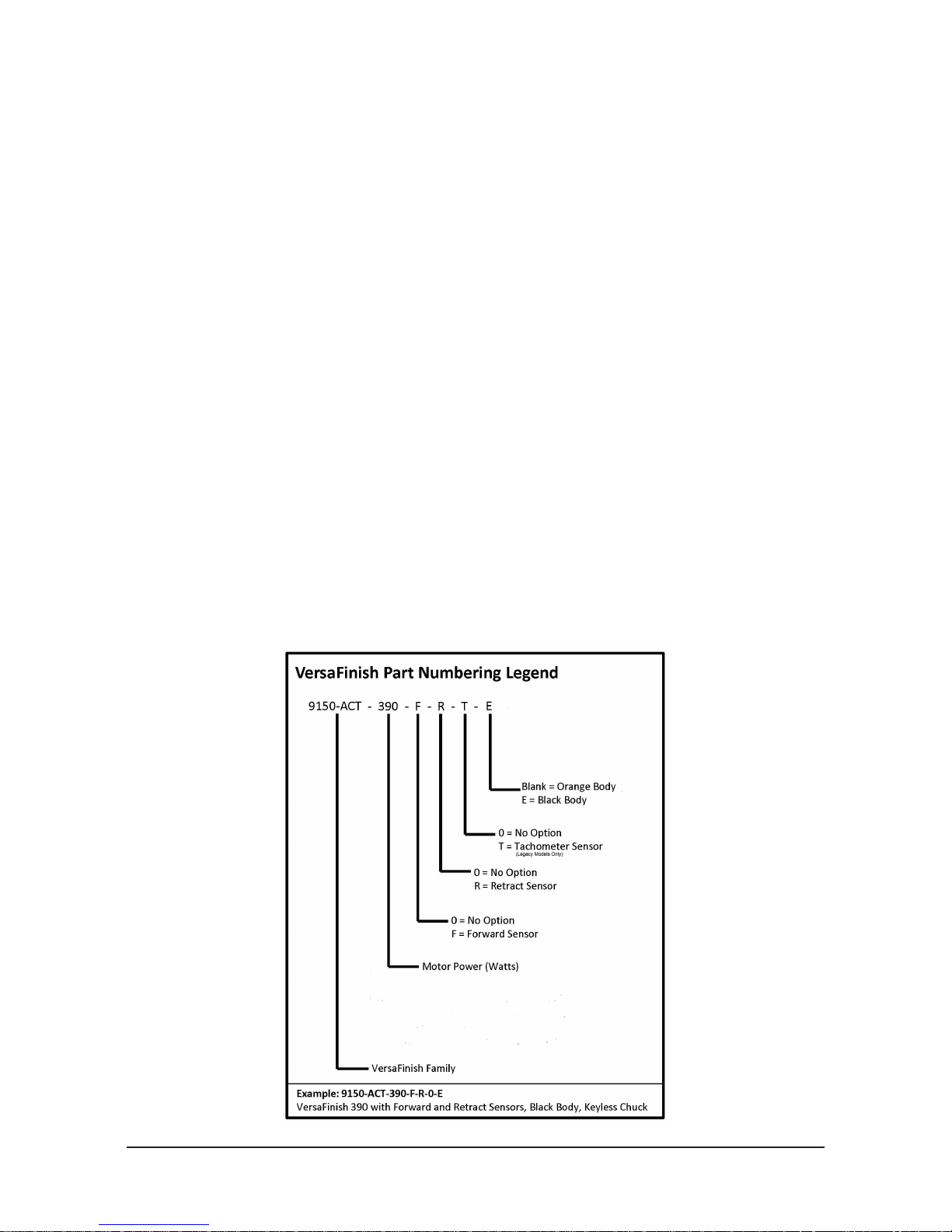
2.2 VersaFinish Part Numbering Legend
Figure 2.2—Part Numbering Legend
Pinnacle Park • 1031 Goodworth Drive • Apex, NC 27539 • Tel: +1.919.772.0115 • Fax: +1.919.772.8259 • www.ati‑ia.com • Email: info@ati‑ia.com
9

Manual, VersaFinish, ACT‑390 Series
Document #9610‑50‑1012‑18
2.3 Technical Description
A technical overview of the product is provided in the following tables and graphs. For additional technical
specications, refer to Section8—Specications.
2.3.1 Environmental Limitations
2.3.1.1 Operation
Installation
position.
Temperature
range
Utilities
Table 2.1—Operation
Mounted to machining center by means various,
customer‑supplied tool holders/adapters.
5° C–35° C
41° F–95° F
The tool requires the following:
• Clean, dry, ltered, and lubricated air (refer to
Section 4.2.2—Lubrication).
• A coalescing lter and lter elements that are rated 5
micron or better.
• The 960 W air motor consumes air at a rate of 19 CFM
(9 l/s) at 6.2 bar (90 psi)
2.3.1.2 Storage
Temperature
range
Conditions
• The axial force/compliance air must be supplied at
0.34 ‑ 4.1 bar (5‑60 psi) from a regulated source.
Table 2.2—Storage
0° C–45° C
32° F–113° F
The tool should be stored in its crate and in a dry place.
When not in use, keep the unit in its crate if possible.
Consult Section 3.4—Storage and Preventive
Maintenance During Storage of this manual.
Pinnacle Park • 1031 Goodworth Drive • Apex, NC 27539 • Tel: +1.919.772.0115 • Fax: +1.919.772.8259 • www.ati‑ia.com • Email: info@ati‑ia.com
10
Manual, VersaFinish, ACT‑390 Series
0.34 1.09 1.84 2.59 3.34 4.09
14
27
40
53
66
3
6
9
12
15
5 15 25 35 45 55
Air Pressure (bar)
Compliance
Force (N)
Compliance
Force (lbs)
Air Pressure (psi)
Document #9610‑50‑1012‑18
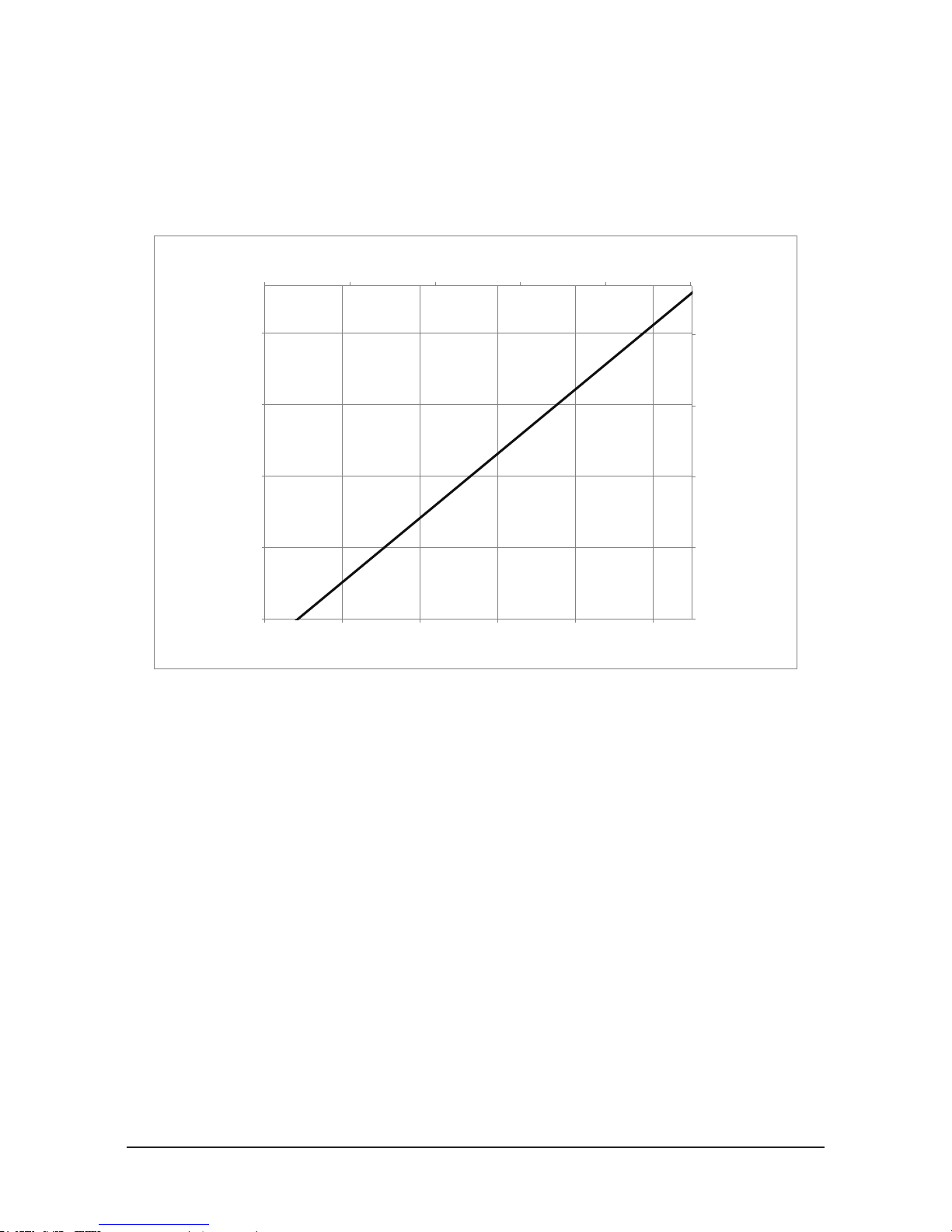
2.4 Compliance Unit Performance
The friction created by the mass of the customer supplied motor resting on the horizontally mounted stage
varies from tool to tool which makes compliance force variable. The compliance force varies linearly with
air pressure using the basic formulas shown in the chart below. Measurements may vary from one product to
another, and should only be treated as nominal.
Figure 2.3—Horizontal Compliance Force Curves
The force characteristics shown are for horizontal, rigidly‑mounted installations. The weight of the motor,
customer supplied chuck, and abrasive media must be added to this if the motor is mounted vertically with
the spindle down or subtracted with the spindle pointed up. Units mounted at angles between horizontal
and vertical provide a compliance force that must be calculated based on the specic mounting geometry or
orientation.
Pinnacle Park • 1031 Goodworth Drive • Apex, NC 27539 • Tel: +1.919.772.0115 • Fax: +1.919.772.8259 • www.ati‑ia.com • Email: info@ati‑ia.com
11
Manual, VersaFinish, ACT‑390 Series
0.0
0.7
1.4
2.0
2.7
3.4
0
0.5
1
1.5
2
2.5
0 1000 2000 3000 4000 5000 6000
Torque (Nm)Torque (lb ‑ft)
RPM
0.0
0.07
0.15
0.2
0.3
0.4
0.5
0
0.1
0.2
0.3
0.4
0.5
0.6
0 1000 2000 3000 4000 5000 6000
Power (kW)Power (hp)
RPM
Document #9610‑50‑1012‑18
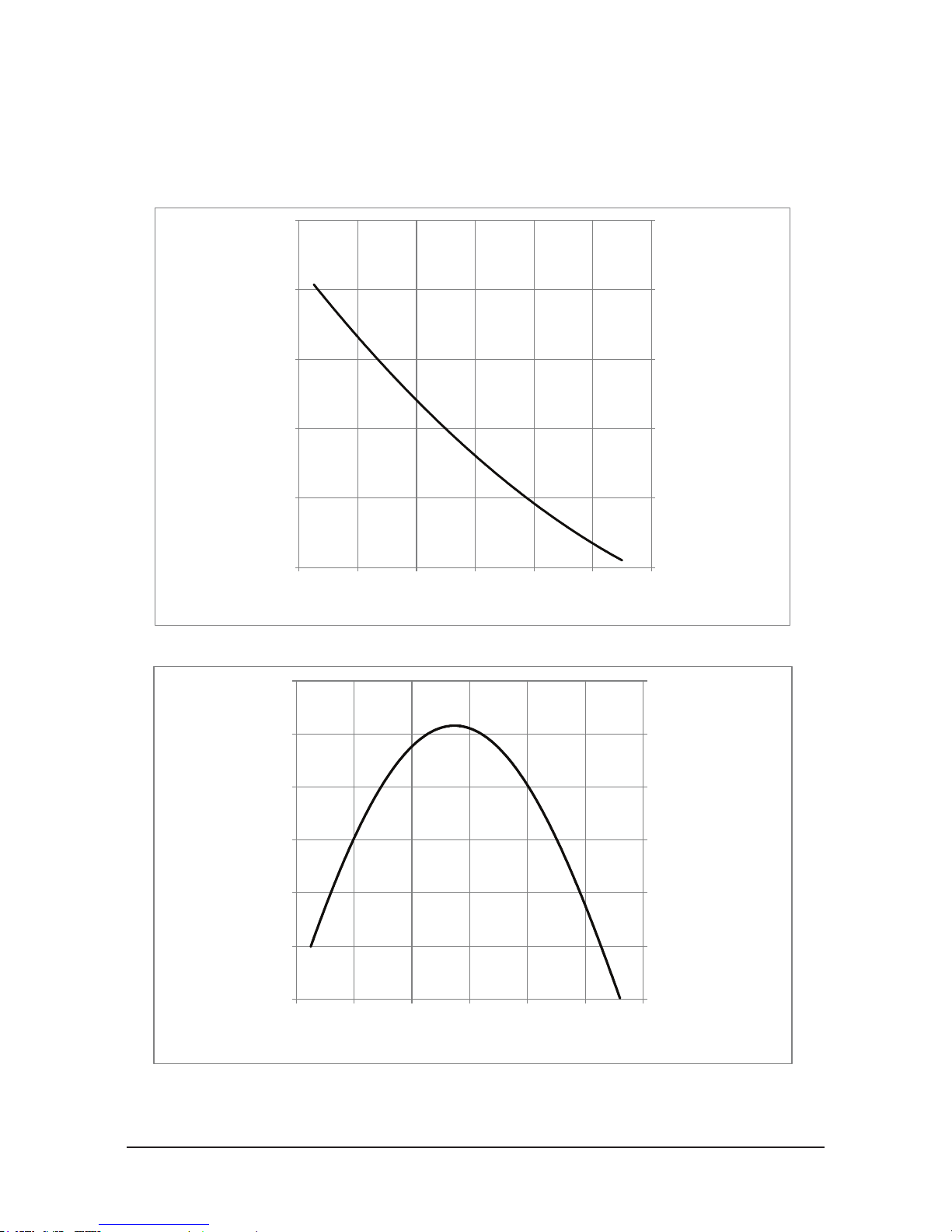
The air motor operating speed will change according to load applied to it developing the power required for
the specic task being attempted. The idle speed of the motor will be its maximum as no load is applied.
This will drop to a lower operating speed where it will develop the maximum torque. If the torque required
exceeds the maximum available, the motor will stall.
Figure 2.4—Motor Torque Curves
Figure 2.5—Motor Power Curves
Pinnacle Park • 1031 Goodworth Drive • Apex, NC 27539 • Tel: +1.919.772.0115 • Fax: +1.919.772.8259 • www.ati‑ia.com • Email: info@ati‑ia.com
12

Manual, VersaFinish, ACT‑390 Series
Document #9610‑50‑1012‑18
3. Installation
The compliance housing incorporates a side mounting pattern which can be used directly or through the use of an
optional bench mount adapter kit. See Section9—Drawings.
The tool must be rigidly mounted prior to use. Under no circumstances should the unit be used for manual/hand
operations. Once securely mounted, the unit should be supplied with clean, lubricated air ltered (5) micron or
better. The use of a coalescing lter is recommended to remove trace moisture from the air supply. Air line ttings
supplying the VersaFinish should be installed with care using a minimum of tape or liquid sealant. To prevent
contaminant damage to the air motor, all air lines should be blown down to remove debris prior to connection of the
VersaFinish.
3.1 Protection During Transportation
The VersaFinish tool arrives in packaging that secures and protects the tool during transportation. Always
use this packaging when transporting the VersaFinish in order to minimize the risk of damage.
3.2 Inspection of Condition When Delivered
Upon receipt, the following should be checked:
• Delivery in accordance with freight documents
• Packaging is in good condition.
If there is damage to any of the packaging, or if any of the goods have been exposed to abnormal handling,
unpack those parts that may have been damaged for a closer inspection. Contact ATI for assistance.
3.3 Unpacking and Handling
The VersaFinish should always be placed inside the accompanying packaging, while transportation, storing,
and handling.
3.4 Storage and Preventive Maintenance During Storage
For short‑term storage, the tool should be stored in its accompanying packaging and in a dry place.
For long‑term storage, the VersaFinish should be thoroughly cleaned of any burrs, dust, or debris. To protect
the air motor, the user may wish to inject several drops of oil directly into the motor input followed by a
short burst of supply air to insure the vanes and internal components are completely lubricated. The units
should not be disassembled. Place the tool inside a sealed, plastic bag and place the bagged tool inside the
crate.
Pinnacle Park • 1031 Goodworth Drive • Apex, NC 27539 • Tel: +1.919.772.0115 • Fax: +1.919.772.8259 • www.ati‑ia.com • Email: info@ati‑ia.com
13
Manual, VersaFinish, ACT‑390 Series
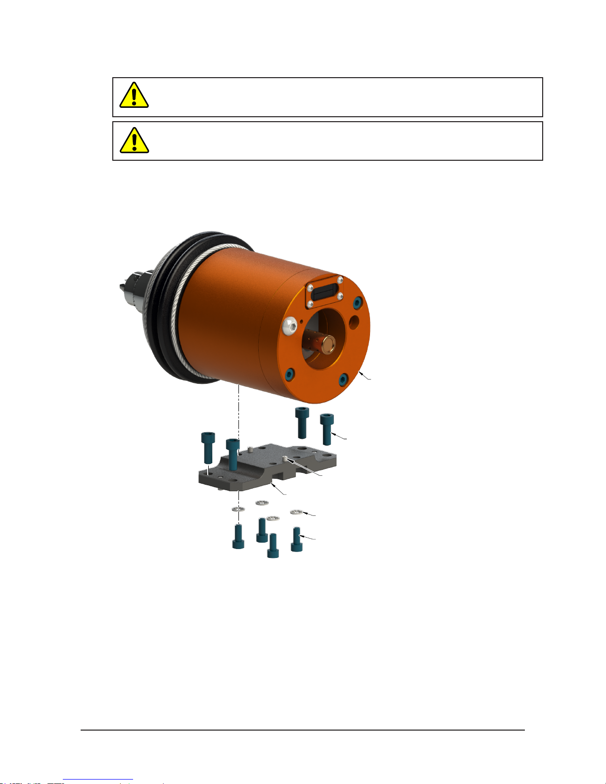
(4) M6 Socket Head Cap Screw
Document #9610‑50‑1012‑18
3.5 Side Mounting Installation
CAUTION: Thread locker applied to fasteners must not be used more than once.
Fasteners might become loose and cause equipment damage. Always apply new
thread locker when reusing fasteners.
CAUTION: The length of the fasteners should not interfere with the compliant motion of
the motor spindle. Refer to Section 9—Drawings for the maximum fastener length. Do
not use fasteners that exceed the maximum length; otherwise, damage will occur.
The side mounting pattern of the ACT nishing tool consists of (2) dowel pin holes and a number of
threaded holes as shown in Figure3.1. If the ACT nishing tool is permanently mounted to a work surface,
the robot carries the part to be nished to the nishing tool.
Figure 3.1—Side Mounting
(2) Dowel Pin
Mounting Bracket
(4) M5 Internal Tooth Washer
(4) M5 Socket Head Cap Screw
Finishing Tool
Pinnacle Park • 1031 Goodworth Drive • Apex, NC 27539 • Tel: +1.919.772.0115 • Fax: +1.919.772.8259 • www.ati‑ia.com • Email: info@ati‑ia.com
14
 Loading...