

Page 1
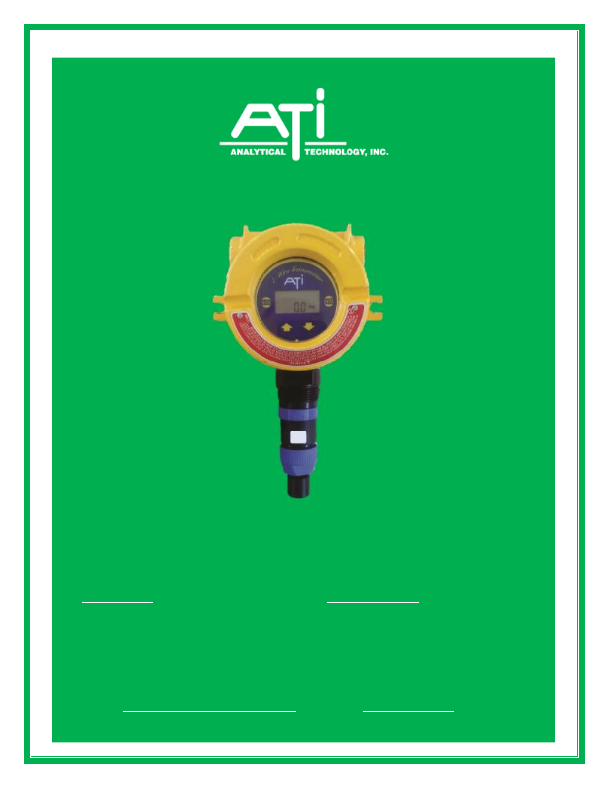
O & M Manual
UniSens
2-Wire Gas Transmitter
Home Office European Office
Analytical Technology, Inc. ATI (UK) Limited
6 Iron Bridge Drive Unit 1 & 2 Gatehead Business Park
Collegeville, PA 19426 Delph New Road, Delph
Phone: 800-959-0299 Saddleworth OL3 5DE
610-917-0991 Phone: +44 (0)1457-873-318
Fax: 610-917-0992 Fax: + 44 (0)1457-874-468
Email: sales@analyticaltechnology.com Email: sales@atiuk.com
Web: www.Analyticaltechnology.com
Fax: 610-917-0992 Fax: + 44 (0)1457-874-468
Page 2

Series A12 Unisens 2-Wire Transmitter
TABLE OF CONTENTS
INTRODUCTION ....................................................................................................................................................3
AUTO-TEST OPTION ..............................................................................................................................4
DUCT MOUNTED SENSORS ..................................................................................................................6
SPECIFICATIONS ...................................................................................................................................................7
INSTALLATION ........................................................................................................................................................8
MECHANICAL MOUNTING ...................................................................................................................8
DUCT MOUNT SENSOR INSTALLATION ...........................................................................................10
SENSING MODULE REMOVAL ............................................................................................................11
CHANGING GAS SENSOR TYPE ...........................................................................................................11
ELECTRICAL CONNECTION .................................................................................................................................12
OPERATION ............................................................................................................................................................14
START-UP .................................................................................................................................................14
STARTUP DELAY ....................................................................................................................................15
FRONT PANEL MAGNETIC CONTROLS .............................................................................................15
LIQUID CRYSTAL DISPLAY .................................................................................................................16
MENU SEQUENCE .................................................................................................................................................17
TRANSMITTER MODE SELECTION .....................................................................................................19
INFORMATION MODE ...........................................................................................................................19
TEST MODE ..............................................................................................................................................19
MANUAL AUTO-TEST ACTIVATION ..................................................................................................19
ANALOG OUTPUT SIMULATION .........................................................................................................20
CALIBRATION .........................................................................................................................................................21
SENSING MODULE ZERO ADJUSTMENT ...........................................................................................22
SENSING MODULE SPAN ADJUSTMENT ...........................................................................................23
CALIBRATION OF DUCT MOUNT SENSORS .....................................................................................24
MA OUTPUT ADJUSTMENT ..................................................................................................................25
UNDER RANGE ENABLE/DISABLE SELECTION ..............................................................................25
AUTO-TEST ENABLE/DISABLE SELECTION .....................................................................................25
ERROR MESSAGES ................................................................................................................................26
FIGURES
Figure 1 - UniSens Transmitter Components ............................................................................................... 5
Figure 2 - UniSens Transmitter w/Duct Sensor Components ...................................................................... 6
Figure 3 - Overall Dimensions ...................................................................................................................... 8
Figure 4 - Wall Mounting Bracket ................................................................................................................. 9
Figure 5 - Duct Mount Sensor Installation .................................................................................................. 10
Figure 6 - Electrical Connections ................................................................................................................ 12
Figure 7 - Remote Electrical Connections .................................................................................................. 13
Figure 8 - UniSens Front Panel .................................................................................................................. 15
Figure 9 - Liquid Crystal Display ................................................................................................................. 16
Figure 10 - Transmitter Program Chart ...................................................................................................... 17
Figure 11 - Sensor Calibration Adapter Assemblies .................................................................................. 22
Figure 12 - Duct Mount Sensor Calibration ................................................................................................ 24
O & M Manual - 2 Rev-L, 7/15
Page 3
Series A12 Unisens 2-Wire Transmitter
GENERAL GASES
OXIDANT GASES
ACID GASES
HYDRIDE GASES
INTRODUCTION
UniSens is a two-wire gas transmitter for use in monitoring hazardous gases in ambient air. It is
designed to monitor gas concentration in areas around storage cylinders, process piping, or gas feed
equipment in virtually any type of industrial plant environment.
The name UniSens signifies the fact that this is a Universal Sensor System. ATI sensor
modules can be interchanged on the universal transmitter to easily reconfigure for a different gas or
range. Sensing modules are available for monitoring a variety of gases and ranges as shown in Table 1.
TABLE 1
GAS CODE NO. STD. RANGE MIN. RANGE MAX. RANGE
Alcohol 39 0-500 PPM 0-500 PPM 0-2000 PPM
Ammonia 15 * 0-100 PPM 0-50 PPM 0-1000 PPM
Carbon Monoxide 16 * 0-100 PPM 0-50 PPM 0-1000 PPM
Ethylene Oxide 37 0-20 PPM 0-20 PPM 0-200 PPM
Formaldehyde 38 0-20 PPM 0-20 PPM 0-200 PPM
Hydrogen 18 0-4 % 0-2000 PPM 0-10 %
Nitric Oxide 25 0-50 PPM 0-25 PPM 0-500 PPM
Oxygen 19 0-25% 0-10% 0-100%
Phosgene 20 0-2 PPM 0-2 PPM 0-200 PPM
Bromine 10 * 0-2 PPM 0-2 PPM 0-100 PPM
Chlorine 11 * 0-10 PPM 0-2 PPM 0-100 PPM
Chlorine Dioxide 12 * 0-2 PPM 0-2 PPM 0-100 PPM
Fluorine 13 * 0-2 PPM 0-2 PPM 0-100 PPM
Hydrogen Peroxide 34 0-10 PPM 0-10 PPM 2000 PPM
Iodine 35* 0-10 PPM 0-2 PPM 0-100 PPM
Ozone 14 * 0-2 PPM 0-2 PPM 0-100 PPM
Hydrogen Chloride 21 * 0-20 PPM 0-10 PPM 0-200 PPM
Hydrogen Cyanide 22 * 0-20 PPM 0-10 PPM 0-200 PPM
Hydrogen Fluoride 23 * 0-20 PPM 0-10 PPM 0-200 PPM
Hydrogen Sulfide 24 * 0-50 PPM 0-10 PPM 0-500 PPM
Nitrogen Dioxide 26 * 0-20 PPM 0-5 PPM 0-200 PPM
Sulfur Dioxide 27* 0-20 PPM 0-10 PPM 0-200 PPM
General Acid Gases 36 * 0-20 PPM 0-5 PPM 0-200 PPM
Arsine 28 0-1000 PPB 0-1000 PPB 0-100 PPM
Diborane 29 0-1000 PPB 0-1000 PPB 0-100 PPM
Germane 30 0-1000 PPB 0-1000 PPB 0-100 PPM
Hydrogen Selenide 31 0-1000 PPB 0-1000 PPB 0-100 PPM
Phosphine 32 0-1000 PPB 0-1000 PPB 0-1000 PPM
Silane 33 0-10 PPM 0-1 PPM 0-100 PPM
* Indicates that Auto-Test is available for standard ranges and lower.
O & M Manual - 3 Rev-L, 7/15
Page 4

Series A12 Unisens 2-Wire Transmitter
UniSens transmitters, also designated Series A12, are loop-powered devices capable of
operating from DC power supplies between 12 and 30 VDC. Normally, this transmitter will be powered
from the 24 VDC supply from a plant wide monitoring computer, a data logger, or an alarm systems that
supplies the DC voltage. The output of the transmitter is a 4-20 mA signal which is linear with respect to
concentration over the range of the sensing module.
Construction of the UniSens transmitter is modular to allow simple installation and maintenance
as shown in Figure 1 on the next page. The transmitter electronics is housed in an aluminum shell with
an 11 pin relay plug on the bottom. The outer housing is an explosion-proof and weatherproof enclosure
with a relay base mounted inside. The transmitter electronics module simply plugs into the relay base,
and all wiring connections are made to that base. Figure 1 shows an exploded view of a complete
UniSens transmitter with sensing module.
The sensing elements used in the UniSens are electrochemical sensors manufactured by ATI.
These sensors are designed for use in ambient air or in ventilation ducts at temperatures of -30° to +50°
C (some sensors rated to -40° C, oxygen sensors rated to -10° C) and at relative humidities between 20
and 98% RH. Use of these sensors in extremely dry air or in condensing gas streams is not
recommended.
Each sensing element is incorporated into a snap-in sensing module, which also contains
electronic memory that is read by the transmitter. This memory contains information on what type of gas
sensor is contained in the module, the range of that particular module, and the calibration constants for
the sensor. When the module is snapped into a transmitter, this data is read into the transmitter
electronics and information related to the module is displayed on the LCD display on the transmitter.
Because all calibration data is stored in the sensing module, these modules can be calibrated using any
spare transmitter and simply snapped into any other transmitter for operation. This unique feature
eliminates the need for field calibration.
AUTO-TEST OPTION
UniSens transmitters are available with an optional feature that eliminates much of the manual
response testing required for toxic gas detection systems. This feature is referred to as Auto-Test, and
consists of a miniature electrochemical gas generator close coupled to the sensor. The generator
produces a "puff" of gas when activated by the transmitter. The response of the sensor is monitored
during this test to be sure that it is still responding to the particular gas, and the output of the transmitter is
driven below 3.7 mA if the sensor does not respond. At the same time, the LCD display indicates that
there was an Auto-Test failure.
The Auto-Test sensor check occurs automatically every 24 hours so that the sensor response is
verified daily. In addition, the Auto-Test can be activated manually at any time using the controls on the
front of the transmitter. During the Auto-Test cycle, the 4-20 mA output is held at 4 mA so that receiving
devices do not alarm during the test. Because most users manually test toxic gas sensor response once
a week, the Auto-Test feature can pay for itself very quickly in reduced labor cost.
O & M Manual - 4 Rev-L, 7/15
Page 5
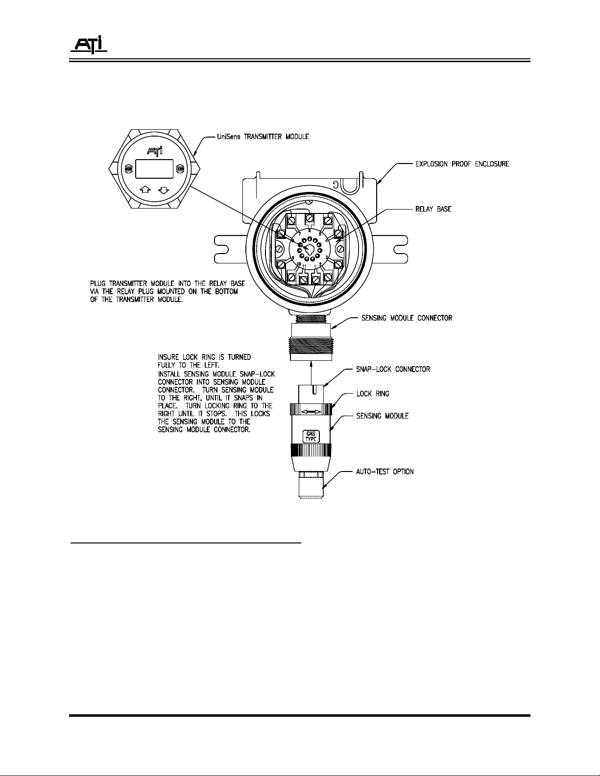
Series A12 Unisens 2-Wire Transmitter
Figure 1 - UniSens Transmitter Components
O & M Manual - 5 Rev-L, 7/15
Page 6
Series A12 Unisens 2-Wire Transmitter
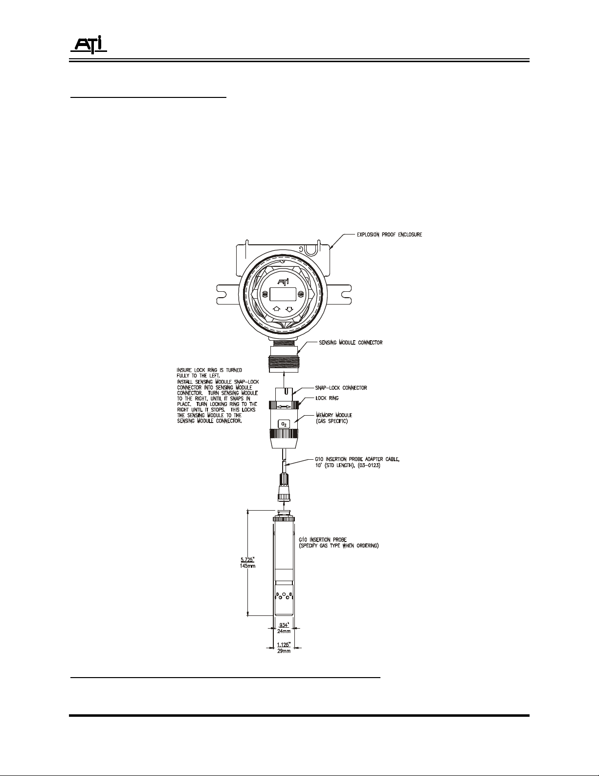
DUCT MOUNTED SENSORS
A special sensor design is available as an option that allows toxic gas sensors to be
inserted into a duct or pipe through a special adapter. This system is designed to allow gas
monitoring in enclosed spaces with easy removal of the sensor for service. The special
mounting fitting provides a method for feeding calibration gas to the sensor without complete
removal from the duct.
Duct mount sensors are provided with a special interface cable so that the transmitter
electronics may be mounted a short distance from the sensing location. Figure 2 below shows
the components of the duct insertion version of the A12 gas transmitter.
Figure 2 - UniSens Transmitter w/Duct Sensor Components
O & M Manual - 6 Rev-L, 7/15
Page 7

Series A12 Unisens 2-Wire Transmitter
SPECIFICATIONS
The following general specifications refer to the UniSens transmitter. Because each sensing
module contains a different sensor, there are specification differences for each gas.
Gas Type: Customer selected from available sensor list.
Range: Supplied with standard range for each gas unless otherwise specified.
Display: 4 1/2 digit LCD
Accuracy: Generally ±5% of value, but limited by available calibration gas accuracy.
Electronic Repeatability: ±1%
Electronic Linearity: ±0.5%
Zero Drift: Sensor dependent, but generally less than 1% of full scale per month, non-cumulative.
Span Drift: Application dependent, but generally less than 3% per month.
Under Range Trip: -20% (when enabled)
Output: Loop-powered 4-20 mA, 750 ohms maximum at 24 VDC loop power
Power: 12-30 VDC
Enclosure: NEMA 4X and Explosion-proof cast aluminum, Class 1, Div. 1, Groups B, C, & D.
Controls: Magnetic links activated externally through glass window. Non-intrusive calibration.
Operating Temperature: -30º to +55º C (except oxygen, which is -10º to +55º C)
Sensor: Modular plug-in unit with calibration data, gas type, and range in sensor memory.
Optional Sensor: Duct insertion sensor with 5 foot interface cable.
Sensor Pressure Limits: 7-30 PSIA (0.5-2 Bar)
Weight: 4 lbs. (1.8 Kg.)
Approvals: CSA Certificate #LR 101166 (Not valid for duct mount sensor)
Intrinsically safe when used with an approved I.S. barrier.
Explosion-proof; Class I, Groups B, C, & D; Class II, Groups E & F, Class III without barrier
O & M Manual - 7 Rev-L, 7/15
Page 8
Series A12 Unisens 2-Wire Transmitter
INSTALLATION
Installation of a UniSens transmitter requires mechanically mounting the enclosure, grounding
the enclosure, and connecting DC power to the system.
MECHANICAL MOUNTING
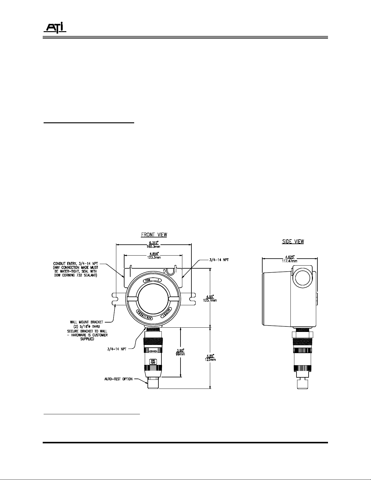
Figure 3 shows the dimensions of the transmitter enclosure and the location and size of the
electrical conduit connection. When used in a classified area, and explosion-proof seal should be
installed as required by the local electrical code. The conduit or cable gland entry into the enclosure must
be sealed with Dow Corning 732 multipurpose sealant. The sealant should be liberally applied to the 3/414 NPT thread on the entry nipple or cable gland before installation. If conduit is used, it must also be
sealed internally at the entry point to the housing. This is required to prevent water condensation inside
the conduit from draining into the enclosure.
- WARNING - Failure to seal the conduit entry or cable gland will result in water entering the
enclosure causing damage or failure to the transmitter electronics.
Figure 3 - Overall Dimensions
O & M Manual - 8 Rev-L, 7/15
Page 9
Series A12 Unisens 2-Wire Transmitter
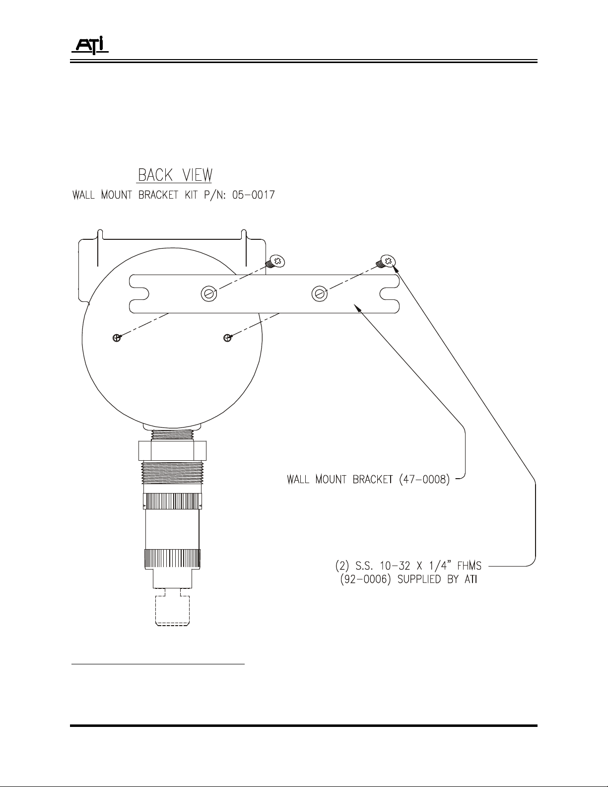
The transmitter enclosure can be mechanically supported by the conduit if proper conduit
fasteners are used. A mounting bracket is supplied with the transmitter for fastening the transmitter
enclosure to a wall or mounting plate. Figure 4 shows the hole center dimension for that mounting
bracket. The mounting bracket attaches to the back of the enclosure with 4 screws supplied with the
bracket.
Figure 4 - Wall Mounting Bracket
O & M Manual - 9 Rev-L, 7/15
Page 10
Series A12 Unisens 2-Wire Transmitter
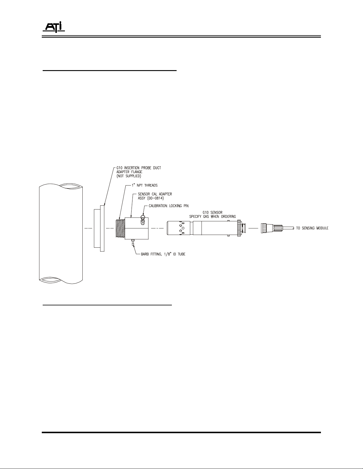
DUCT MOUNT SENSOR INSTALLATION
Duct mounted sensors are designed to be inserted into an air duct or pipe through a special
adapter fitting (part number 00-0814). This fitting has a 1” MNPT thread on the front for adapting to the
duct or pipe. The actual duct adapter is customer supplied.
Installation of this sensor requires that the 00-0814 adapter be screwed into the customer
supplied adapter as shown in Figure 5 below. Screw in the adapter so that the calibration gas inlet port is
oriented in a direction that gas tubing can easily be connected. Once the adapter is in place, the sensor
will slide into the adapter easily. However, it is recommended that the sensor not be installed in the fitting
until you are ready to start up the transmitter. This is especially true during construction when dust and
dirt may be blowing through the duct system. Fouling of the sensor may result.
Figure 5 - Duct Mount Sensor Installation
O & M Manual - 10 Rev-L, 7/15
Page 11

Series A12 Unisens 2-Wire Transmitter
SENSING MODULE REMOVAL
UniSens sensor modules are easily inserted and removed from transmitters to allow
bench calibration and simplify field service. To remove the sensor module from the transmitter,
be sure that the lock ring is turned fully to the left. From the locked position, the lock ring will
turn 1/2 turn. Do not attempt to remove the sensor module with the lock ring in the locked
position.
After unlocking the lock ring, grab the black portion of sensor module between your
thumb and forefinger and turn the entire module to the left 1/8th turn. Pull the module straight
down and it will disengage from the module holder.
To install a sensor module, reverse the procedure described above. Be sure that the
lock ring is in the unlocked position prior to attempting module installation. With the lock ring in
the locked position, the sensor module will not snap into proper position and the transmitter will
indicate a series of bars across the LCD display, indicating that there is no sensor module
installed.
NOTE: When a sensing module is unplugged from an operating transmitter, the output of
the transmitter will drop below 3.2 mA, which indicates a trouble condition.
However, there is a 30 second time delay on this trouble indication. When a
sensing module is removed, the LCD display will begin counting down from 30.
During the countdown, the output will be held it's value prior to unplugging the
module. When the display reaches zero, the output will fall to the trouble
condition value below 3.2 mA. This delay allows inspection or substitution of
modules without affecting receiving instruments.
CHANGING GAS SENSOR TYPE
UniSens transmitters will accept sensor modules for all of the gases listed on page 3. Note that
each gas has a specific code number. The transmitter stores the code number for any sensor module
removed from it. If you plug in a sensor module that contains a different gas code number than the one
removed, the transmitter will not load any data. Instead, it will wait for confirmation from the operator that
a change in gas type is desired. The display will indicate “CXX” with the XX indicating the code number
of the new gas sensor plugged into it. For instance, if you remove a chlorine sensor, code 11, and then
plug in an HCl sensor, the display will indicate “C21”, which indicates it is waiting for confirmation that you
want to change the transmitter function from chlorine to hydrogen chloride. Activate the ENTER switch
with the magnetic screwdriver and the HCl sensor module data will load.
Note: Sensors can take up to 12 hours to stabilize (bias) when placed into service unless
the sensor was stored in the sensor keeper.
O & M Manual - 11 Rev-L, 7/15
Page 12

Series A12 Unisens 2-Wire Transmitter
ELECTRICAL CONNECTION
Standard transmitters are supplied with the sensing module connector factory wired to the relay
base. The only connections required for installation are the two loop connections and earth ground to the
enclosure. Figure 6 shows the proper terminals for loop wiring and the earth ground connection point.
The transmitter module can be removed from the outer enclosure by gently rocking it back and forth while
pulling out.
Sensing module holders are available with up to 5 feet of cable for remoting the sensor from the
transmitter. When supplied in this configuration, electrical installation will also require connection of
sensing module holders to the relay base. An 8 conductor cable connects the holder to the base, and
Figure 6 provides the wiring diagram for connection of the holder to the relay base.
Figure 6 - Electrical Connections
O & M Manual - 12 Rev-L, 7/15
Page 13

Series A12 Unisens 2-Wire Transmitter
Figure 7 - Remote Electrical Connections
O & M Manual - 13 Rev-L, 7/15
Page 14

Series A12 Unisens 2-Wire Transmitter
OPERATION
After mechanical and electrical installation is complete, the transmitter is ready for operation.
Prior to start-up, recheck the loop wiring connection to be sure it's correct. Reversing the loop wiring will
not damage the transmitter, but other devices in the loop may be adversely affected.
START-UP
When power is first applied, the transmitter will go through a start-up sequence. The LCD display
will indicate the following information.
Load Indicates that sensor module data is loading into the transmitter
tr 1.0 Indicates transmitter program version number
Sr 1.0 Indicates sensing module revision level
XX Two digit gas code number (see table 1)
XXXX PPM Number indicating the full scale range of the sensing module
Ur E / Ur d Ur E – Indicates that the signal trouble on under range function is enabled
Ur d – Indicates that the signal trouble on under range function is disabled
InSt/nonE InSt - Indicates that Auto-Test function is installed in sensor module
nonE - Indicates that sensor module does not contain an Auto-Test
generator
Enab/disA Enab - Indicates that the Auto-Test function is enabled.
disA - Indicates that the Auto-Test function is disabled.
XX.XH Number of hours until the next scheduled Auto-Test (in hours)
XXXX Number of successful sensor tests using the Auto-Test generator
XXXX Number of unsuccessful sensor tests using the Auto-Test generator
All Segments Display test which powers up all display segments and flags
O & M Manual - 14 Rev-L, 7/15
Page 15

Series A12 Unisens 2-Wire Transmitter
STARTUP DELAY
When the start-up sequence is complete, the display will begin to indicate gas concentration and
will display the mA lock flag, indicating that a start-up delay is in progress and that the mA output is
locked at 4.0 mA (except for oxygen transmitters, where the loop will be locked at 17.4 mA, the equivalent
of 20% O2). The delay period is 5 minutes, which provides time for the sensor to stabilize near zero
before the output is released. After 5 minutes, the lock flag will disappear and the output will begin to
track the gas concentration.
NOTE: For new installations where the sensor has been unpowered for an extended period, the 5
minute start-up delay may not be sufficient for the sensor to completely zero. Some sensors can
take up to 30 minutes to completely stabilize when unpowered for an extended period of time.
FRONT PANEL MAGNETIC CONTROLS
The front of the transmitter module contains 4 magnetically activated controls. As shown in
Figure 7, these controls are MODE, ENTER, UP, and DOWN. A screwdriver with a suitable magnet is
supplied with each transmitter. This magnet allows for operation of the transmitter controls without
removing the cover of the outer enclosure. Magnetic controls are used for displaying information about
the operation of the transmitter, and performing zero and calibration functions. These controls also allow
manual activation of the Auto-Test function if installed, and simulating the 4-20 mA output at 4 different
values for full loop verification.
Figure 8 - UniSens Front Panel
O & M Manual - 15 Rev-L, 7/15
Page 16

Series A12 Unisens 2-Wire Transmitter
LIQUID CRYSTAL DISPLAY
The display in the A12 transmitter provides the operator with a real time concentration display
and a variety of prompts for selecting transmitter operating modes. Figure 8 shows the display, including
all of the special indicators contained in it. Below that Figure is a description of each of the indicators.
Figure 9 - Liquid Crystal Display
A - Digital Concentration Display
B - Zero Indicator, activated while zeroing a sensor module or adjusting the 4 mA output value.
C - Span Indicator, activated while spanning a sensor module or adjusting the 20 mA output value.
D - Down Key Indicator, activated when the magnetic control marked "∇" is activated.
E - Up Key Indicator, activated when the magnetic control marked "∆" is activated.
F - Auto-Test Indicator, activated when the transmitter is running the Auto-Test routine.
G - Fail Indicator, activated when an Auto-Test failure occurs.
H - mA Indicator, activated during output simulation mode or when the output is locked.
I - PPB Indicator, activated when a sensor module with a Part-Per-Billion range is installed
J - PPM Indicator, activated when a sensor module with a Part-Per-Million range is installed
K - LEL Indicator, activated when a sensor module with a Percent Lower Explosive Limit range is installed
L - % Indicator, activated when a sensor module with a Percent (or % LEL) range is installed
O & M Manual - 16 Rev-L, 7/15
Page 17

Series A12 Unisens 2-Wire Transmitter
MENU SEQUENCE
Operation of the transmitter is accomplished from the front panel using magnetic controls, with
the LCD providing visual indication of menu selections. Through menu selections, the user can review
information about the transmitter, calibrate the transmitter, manually activate the Auto-Test function (if
installed), simulate 4 different mA output values, and reset the transmitter to normal operation in the event
of an Auto-Test failure. Figure 9 provides a block diagram of the program in the UniSens transmitter.
Figure 10 - Transmitter Program Chart
O & M Manual - 17 Rev-L, 7/15
Page 18

Series A12 Unisens 2-Wire Transmitter
O & M Manual - 18 Rev-L, 7/15
Page 19

Series A12 Unisens 2-Wire Transmitter
TRANSMITTER MODE SELECTION
The transmitter provides 4 main mode selections. After the display scrolls through the power-up
sequence and completes the start-up delay, it enters the NORMAL mode of operation, displaying gas
concentration. By holding a magnet over the MODE control, the display will indicate "InFo". Repeating
this process will change the display to "tESt" and then "CAL". The meaning of these modes is as follows:
InFo Designates INFORMATION mode. In this mode, you may review the information initially
displayed during the power-on sequence.
tESt Designates TEST mode. In this mode, the Auto-Test generator may be manually
activated, and the 4-20 mA output may be tested at 4 set values.
CAL Designates CALIBRATION mode. In this mode, the zero and span of the sensing
module may be adjusted, the 4 and 20 mA output current can be adjusted, and the AutoTest generator can be enabled or disabled.
INFORMATION MODE
To review the transmitter information, activate the MODE control until the display shows "InFo"
and then activate the ENTER control. The display will scroll through the same information shown during
power-up. See page 10 for details on the information displays.
TEST MODE
There are two selections available under the TEST menu. The first selection allows manual
activation of the Auto-Test by the operator. The second selection allows the transmitter output to be set
to 4, 12, and 20 mA in order to check the devices tied to the output. In addition, a failure condition can be
simulated, causing the output to go to about 3.6 mA.
MANUAL AUTO-TEST ACTIVATION
From the NORMAL display, activate the MODE control twice and the display will read "tESt".
Activate the ENTER control. If a sensing module with Auto-Test generator is installed, the display will
change to "SEnS" and the AUTO TEST flag will be displayed near the top of the display. If you activate
the ENTER control at this point, the Auto-TEST sequence will begin and the AUTO TEST flag will begin
to flash. Activating the MODE control will allow you to escape from this routine without activating the test
sequence.
O & M Manual - 19 Rev-L, 7/15
Page 20

Series A12 Unisens 2-Wire Transmitter
When the test sequence is activated, the 4-20 mA output will be locked at the value
being transmitted before the sequence began, normally close to 4.0 mA. If you observe the
LCD, you will see the gas concentration begin to increase as gas is evolved from the generator. When
the display reaches 10% above the start value, a PASS message will flash on the display, indicating that
the sensor passed the test. At this point the AUTO TEST flag will stop flashing and go to steady on. This
indicates that the Auto-Test was successful but that the 4-20 mA output is still locked. The output will
stay locked for the next 2 minutes to allow the sensor to recover to zero. In addition, it will remain partially
locked for an additional 8 minutes to insure complete sensor recovery before again activating the output.
However, if the measured gas concentration goes above 50% of range during the second 8 minute inhibit
period, the output lock is released and any receivers connected to the transmitter will indicate high gas
levels.
ANALOG OUTPUT SIMULATION
The UniSens transmitter provides the ability to simulate 4 different current output values in order to
verify complete loop integrity and to calibrate receiving devices. The output may be set to values of 4.0, 12.0,
and 20.0, and may also be set to the "Trouble" value below 3.7 mA.
From the NORMAL display, activate the MODE control twice and the display will read "tESt".
Activate the ENTER control. If a sensing module with Auto-Test generator is installed, the display will
change to "SEnS" and the TEST flag will be displayed near the top of the display. Activate the MODE
control once and the display will change to tESt and the mA flag will be on. Activate the ENTER control
once and the display will indicate 4 mA. The current output from the transmitter will now be locked on 4
mA. Use the UP or DOWN control to change the output to 12 mA, 20 mA, or "trbl" as desired. When
"trbl" is displayed, the output will go below 3.7 mA, which is the output value used to indicate "Trouble"
with the transmitter. The output current from the transmitter will change to the value shown on the
display.
CAUTION: Simulation of 12 or 20 mA outputs may cause receiving devices to activate alarms
and/or control devices. Never simulate these outputs without inhibiting alarm receivers
or notifying operating personnel that a system test is in progress.
To escape the output simulation mode, activate the ENTER control once.
O & M Manual - 20 Rev-L, 7/15
Page 21

Series A12 Unisens 2-Wire Transmitter
CALIBRATION
UniSens transmitters should be calibrated every 3-6 months. However, the concept of calibration
is a little different with this product. Because calibration constants are stored in the sensing module, you
are really calibrating the sensing module rather than the transmitter itself.
The frequency of calibration is dependent on the operating environment (sensors exposed to dirt,
oil mist, or vapors need more frequent calibration) and the degree to which accuracy is important.
Generally, more frequent calibration is done if the gas transmitter is located where personnel are working
regularly.
Sensing module calibration requires adjustment of both sensor zero and span. Sensor zero is
adjusted when the sensor is exposed to zero air. Adjusting the span requires a source of span gas with a
known concentration of the particular gas. Calibration kits, containing both zero air and span gas, are
available from ATI for many toxic gases. Contact ATI or your local ATI representative if you have any
questions on calibration gas sources.
Calibration span gas for some gases, such as HCl, Ozone, or Hydrides, are either very expensive
or not available at all. Calibration of these sensors require specialized equipment, and it may be more
convenient and economical to use ATI's calibration services for this function. The unique design of the
sensing module allows this to be done easily. Because calibration constants are stored in memory in the
sensing module, the complete module can be sent to ATI for adjustment when needed. During factory
calibration, new calibration constants will be stored in the sensing module. When this module is snapped
into the original transmitter, these new constants will be read into the transmitter memory, automatically
adjusting the transmitter for that sensing module. Contact ATI at 800-959-0299 for details on factory
calibration services.
NOTE: The output of the A12 transmitter is locked at 4 mA when in the calibration mode, except for
oxygen transmitters, which are locked at 17.4 mA. This means that the 4-20 mA output will not
change when span gas is applied. Only the LCD display will indicate changing gas
concentrations. To verify output operation using span gas, apply gas while the transmitter is in
the NORMAL mode of operation after calibration is complete.
O & M Manual - 21 Rev-L, 7/15
Page 22

Series A12 Unisens 2-Wire Transmitter
SENSING MODULE ZERO ADJUSTMENT
As previously mentioned, adjusting the sensing module zero requires that the sensor be exposed
to air that is free of the target gas or any other gases that might cause either negative or positive
interference to that sensor. Refer to the section of this manual related to the specific gas type for
information on potential interferences.
If the area in which the sensor is operating is know to be gas free, then the sensing module can
be zeroed without further equipment. If not, use of "zero air" from a gas cylinder is recommended. Zero
air is available as part of all ATI calibration kits, or may be obtained from any specialty gas supplier.
When zero air is to be used, a calibration adapter (part no. 00-0248) must be used. The calibration
adapter provides a confined space around the sensor into which the zero air can flow. There are two
calibration adapters available for A12 sensor modules. For D10 modules without Auto-Test, the adapter
slips inside the splash guard for the sensor module. For D28 modules with Auto-Test generator, the
adapter slides on to the generator.
Note: The gas inlet port (1/8” barb fitting) on the adapter used for the D28 module must be unscrewed
partially to allow the adapter to slide over the generator. When in place, screw the fitting in so
that it is retained in the slot between the generator and sensor.
Figure 11 - Sensor Calibration Adapter Assemblies
O & M Manual - 22 Rev-L, 7/15
Page 23

Series A12 Unisens 2-Wire Transmitter
To zero the transmitter, allow zero air to flow to the sensor for 5 minutes. If the sensor is located
in air known to be gas free, follow the steps below to adjust the zero.
Step 1 With the LCD indicating normal mode of operation, activate the MODE control repeatedly until the
display shows "CAL". Then activate the ENTER control. The display will change to "SEL" and
the "Z" (for Zero) flag on the display will light.
Step 2 Activate ENTER again and the display will change to an indication of the current gas
concentration. The value should be close to zero. Observe the display to be sure it is not either
increasing or decreasing.
Step 3 When the display value is stable, activate ENTER again and any small sensor offset will be
stored in memory. The display will change to "SEL" and the "S" (for Span) flag will light. If you
wish to span the sensing module, activate ENTER and proceed to the next section of this manual.
If you only wish to set the zero, activate MODE until the display indicates "donE". Activate
ENTER to return to the normal operating mode.
SENSING MODULE SPAN ADJUSTMENT
Adjusting the sensing module span requires a source of reliable span gas. If possible, a span
gas with a gas concentration of at least 25% of the full scale sensing module span is recommended. For
example, if the full scale span is 20 PPM, span gas of at least 5 PPM should be used. Many span gases
are available in convenient disposable cylinders, while other gases require a permeation system to
generate a reliable standard. DO NOT ATTEMPT TO ADJUST THE SPAN OF A SENSING MODULE
WITHOUT A RELIABLE SPAN GAS.
To adjust the sensing module span, proceed as follows:
Step 1 Advance through the transmitter program using the MODE and ENTER controls until the display
indicates "SEL" and the "S" flag is lit. This display is indicating that you can now select the span
mode.
Step 2 Activate ENTER and the display will indicate gas concentration. The "S" flag will remain lit.
Step 3 Screw a calibration adapter onto the sensing module as shown in Figure 8. Connect your span
gas source to the inlet fitting on the cal. adapter.
Step 4 Turn on the flow of calibration gas and allow it to flow for 5 minutes. The LCD display should
increase in response to the sensor being exposed to the target gas. After 5 minutes, use either
the UP or DOWN controls to adjust the value on the display to the span gas value.
Step 5 Activate ENTER and the new span constant will be stored in the sensing module. The display will
now indicate "donE". Activate ENTER to return to normal operation.
O & M Manual - 23 Rev-L, 7/15
Page 24

Series A12 Unisens 2-Wire Transmitter
CALIBRATION OF DUCT MOUNT SENSORS
The procedure for zeroing and calibration of duct mounted gas sensors is similar to that
described on pages 22 and 23 except that the calibration is done with the sensor still mounted inside the
mounting adapter fitting. This fitting contains a calibration gas connection on the side. See figure 11
below for the sensor orientation when in the calibrate position.
To zero and calibrate the duct sensor, pull the sensor out of the duct until the retaining pin clicks
into the retaining slot. If you pull the sensor back slowly, the retaining pin will drop into place and
automatically locate the sensor in the proper position opposite the gas inlet port. Connect your zero or
span gas to the gas connection port and follow the zero and span adjustment procedures from the
previous 2 pages.
Figure 12 - Duct Mount Sensor Calibration
O & M Manual - 24 Rev-L, 7/15
Page 25

Series A12 Unisens 2-Wire Transmitter
MA OUTPUT ADJUSTMENT
Series A12 transmitters provide a method of adjusting (or offsetting) the 4 and 20 mA output
values slightly in order to insure that other devices in the output loop read the correct value. In effect,
these adjustments are the equivalent of fine zero and fine span controls.
Adjustment of the 4 and 20 mA values is done through the CAL mode. From the NORMAL
display, activate MODE until the display reads "CAL". Activate ENTER once and then MODE twice so
that the display reads "SEL" with the Z and mA indicators on. Activate ENTER and the display will
change to "SET", with the Z and mA indicators still on. Use the UP or DOWN controls to move the 4 mA
value up or down as required. The display will not indicate the output value. This must be read using a
mA meter or by observing another display tied to the transmitter output.
When adjustment is complete, activate the ENTER control and the display will change to "SEL"
with the S and mA indicators on. Activate ENTER and repeat the above process to adjust the 20 mA
value as required. When adjustment is finished, activate ENTER to store the value and ENTER again
when the display indicates "donE". This will take you back to the NORMAL display and mode of
operation.
UNDER RANGE ENABLE/DISABLE SELECTION
The trouble on Under range function can be enabled or disabled from the software menu.
Normally, this function will be enabled so that sensor under range conditions greater than – 20% full scale
will cause the transmitter to output the trouble value of 3mA.
To disable this function, start from the normal display and activate the MODE control three times
to display “CAL”. Activate ENTER once and then the MODE control four times. The display should now
indicate “Ur E”. Use the UP or DOWN control to toggle to “Ur d”. The under range function is now
disabled. Activate the MODE control twice to display “done”. Use ENTER to return to the Normal display.
AUTO-TEST ENABLE/DISABLE SELECTION
The Auto-Test function on a series A12 transmitters can be activated (enabled) or deactivated
(disabled) from the software menu. Normally, this function will be enabled at all times so that the sensor
response is verified regularly. However, should a problem arise with the generator, the Auto-Test
function can be disabled while a new module or generator is obtained. If the sensor is still functional,
disabling the Auto-Test allows the transmitter to continue normal operation without attempting its normal
24 hour test sequence.
If the transmitter was shipped with a sensor module containing an Auto-Test generator, the AutoTest function will be enabled at the factory. To disable this function, start from the NORMAL display and
activate the MODE control three times to display "CAL". Activate ENTER once and then the MODE
control 4 times. The display should now indicate "EnAb". Use the UP or DOWN control to toggle to
"dISA". Activate the ENTER control to store the disable value. When the display indicates "donE", use
ENTER to return to the NORMAL display.
O & M Manual - 25 Rev-L, 7/15
Page 26

Series A12 Unisens 2-Wire Transmitter
ERROR MESSAGES
The A12 constantly evaluates the condition of the sensor and the output loop to detect errors that
might compromise the performance of the instrument. The following messages will appear on the LCD
display if the transmitter detects certain failures.
AUTO TEST FAIL
FAIL
U.r.
: This message is displayed if the transmitter is equipped with the Auto-Test option and the
sensor fails to respond to 3 successive tests at one hour increments. Unusual
environmental conditions can cause an occasional test failure, so the system will retest the
sensor an hour later if a failure occurs. After 3 failures, the AUTO TEST FAIL message
appears and the output goes to 3 mA. If this occurs, test the sensor with calibration gas to
determine if the failure is due to the sensor or the gas generator. Sensor or generator
replacement will most likely be needed. Should the Auto-Test failure message appear
due to a generator failure, the transmitter will still perform its function. Activating the
ENTER key will clear the alarm. Should the sensor detect a level above 50% of the full
scale range, the failure condition will be over-ridden and the output will immediately reflect
the measured gas value.
: This message is displayed when the transmitter has detected a negative zero drift greater
than 20% of full scale. The transmitter output is locked at 3 mA. The display will alternate
between the current gas concentration and “U.r.”. The unit should be checked for proper
operation. Sensor zero should be set and system response should be checked. Activating
the ENTER key will clear the alarm.
This condition is common with some types of sensors when a transmitter is initially
installed. Some sensors exhibit a negative zero offset when they have been unbiased for a
long period of time, such as when in storage. If this message appears on initial startup,
allow the transmitter to run undisturbed for at least one to two hours. Then press ENTER
and the condition will clear. Should the sensor detect a level above 50% of the full scale
range, the failure condition will be over-ridden and the output will immediately reflect the
measured gas value.
O & M Manual - 26 Rev-L, 7/15
Page 27

Series A12 Unisens 2-Wire Transmitter
SPARE PARTS
Series A12 Two-Wire Gas Transmitter
PART NO. DESCRIPTION
03-0071 Transmitter module (no enclosure or relay base)
03-0063 Transmitter x-proof enclosure, base, module connector
03-0111 Transmitter x-proof enclosure, base, module connector with 5 ft. cable
03-0070 Sensing module connector assembly with 8" cable
03-0065 Sensing module connector assembly with 5 ft. cable
03-0067 Earth GND Jumper
05-0021 Transmitter relay base with earth ground jumper (kit)
00-0248 D10 (no Auto-Test) Sensor Calibration Adapter
00-1197 D28 (w / Auto-Test) Sensor Calibration Adapter
00-0249 Flowcell assembly
45-0047 Splash guard
00-0210 Sensing module keeper
05-0017 Kit - Wall Mounting Bracket
SENSING MODULES (range for each module must be specified)
No A/T (D10) With Auto-Test (D28)
00-0211 00-0212 Bromine
00-0213 00-0214 Chlorine
00-0215 00-0216 Chlorine Dioxide
00-0217 00-0218 Fluorine
00-0219 00-0220 Ozone
00-0221 00-0222 Ammonia
00-0223 00-0224 Carbon Monoxide
00-0225 N/A Hydrogen (PPM Range)
00-0260 N/A Hydrogen (% Range)
00-0226 N/A Oxygen
00-0227 N/A Phosgene
00-0228 00-0229 Hydrogen Chloride
00-0230 00-0231 Hydrogen Cyanide
00-0232 00-0233 Hydrogen Fluoride
00-0234 00-0235 Hydrogen Sulfide
00-0236 N/A Nitric Oxide
00-0237 00-0238 Nitrogen Dioxide
00-0239 00-0240 Sulfur Dioxide
00-0241 N/A Arsine
00-0242 N/A Diborane
00-0243 N/A Germane
00-0244 N/A Hydrogen Selenide
00-0245 N/A Phosphine
00-0246 N/A Silane
00-0247 N/A Hydrogen Peroxide
00-0430 00-0431 Iodine
00-0682 N/A Super High Range Phosphine (1000 PPM)
00-0785 N/A Alcoho
O & M Manual - 27 Rev-L, 7/15
Page 28

Series A12 Unisens 2-Wire Transmitter
SENSOR ONLY
PART NO. DESCRIPTION
00-0264 E10-XX Low Range Oxidant Sensor (F2, Br2, I2, ClO2), under 3 PPM
00-0265 E10-XX High Range Oxidant Sensor (F2, Br2, I2, ClO2), 5 PPM & Above
00-0266 E10-27 Sulfur Dioxide Gas Sensor
00-0267 E10-15 Ammonia Gas Sensor
00-0268 E10-23 Hydrogen Fluoride Gas Sensor
00-0269 E10-21 Hydrogen Chloride Gas Sensor
00-0270 E10-22 Hydrogen Cyanide Gas Sensor
00-0271 E10-19 Oxygen Gas Sensor
00-0272 E10-18 Hydrogen Gas Sensor
00-0273 E10-24 Hydrogen Sulfide Gas Sensor
00-0274 E10-16 Carbon Monoxide Gas Sensor
00-0275 E10-25 Nitric Oxide Gas Sensor
00-0276 E10-26 Nitrogen Dioxide Gas Sensor
00-0277 E10-33 High Range Hydride (Silane) Gas Sensor
00-0278 E10-28 Low Range Hydride (0-1000 PPB) Gas Sensor
00-0279 E10-20 Phosgene Gas Sensor
00-0280 E10-34 Hydrogen Peroxide Gas Sensor
00-0292 E10-14 Low Range Ozone Gas Sensor
00-0681 E10-32 Super High Range Phosphine (1000 PPM)
00-0731 E10-39 Alcohol Gas Sensor
00-1111 E10-14 High Range Ozone Gas Sensor
SENSOR AND GENERATOR
00-0282 E28-14 Low Range Oxidant Sensor/Generator
00-0283 E28-11 Chlorine Gas Sensor/Generator
00-0284 E28-27 Sulfur Dioxide Gas Sensor/Generator
00-0285 E28-15 Ammonia Gas Sensor/Generator
00-0286 E28-23 Hydrogen Fluoride Gas Sensor/Generator
00-0287 E28-21 Hydrogen Chloride Gas Sensor/Generator
00-0288 E28-22 Hydrogen Cyanide Gas Sensor/Generator
00-0289 E28-24 Hydrogen Sulfide Gas Sensor/Generator
00-0290 E28-16 Carbon Monoxide Gas Sensor/Generator
00-0291 E28-26 Nitrogen Dioxide Gas Sensor/Generator
00-1112 E28-14 High Range Ozone Gas Sensor/Generator
00-1113 E28-14 Low Range Ozone Gas Sensor/Generator
O & M Manual - 28 Rev-L, 7/15
Page 29

Series A12 Unisens 2-Wire Transmitter
INSERTION SENSORS
00-0815 G10-xx Lo Oxidant
00-0816 G10-xx Hi Oxidant
00-0817 G10-15 Ammonia
00-0818 G10-16 Carbon Monoxide
00-0819 G10-18 Hydrogen
00-0820 G10-19 Oxygen
00-0821 G10-20 Phosgene
00-0822 G10-21 Hydrogen Chloride
00-0823 G10-22 Hydrogen Cyanide
00-0824 G10-23 Hydrogen Fluoride
00-0825 G10-24 Hydrogen Sulfide
00-0826 G10-25 Nitric Oxide
00-0827 G10-26 Nitrogen Dioxide
00-0828 G10-27 Sulfur Dioxide
00-0829 G10-xx Lo Range Hydride
00-0830 G10-xx Hi Range Hydride
00-0831 G10-xx Super Hi Hydride
00-0832 G10-34 Hydrogen Peroxide
00-0833 G10-39 Alcohol
00-1109 G10-14 Low Range Ozone
00-1110 G10-14 High Range Ozone
O & M Manual - 29 Rev-L, 7/15
Page 30

PRODUCT WARRANTY
Analytical Technology, Inc. (Manufacturer) warrants to the Customer that if any
part(s) of the Manufacturer's products proves to be defective in materials or
workmanship within the earlier of 18 months of the date of shipment or 12 months of the
date of start-up, such defective parts will be repaired or replaced free of charge.
Inspection and repairs to products thought to be defective within the warranty period will
be completed at the Manufacturer's facilities in Collegeville, PA. Products on which
warranty repairs are required shall be shipped freight prepaid to the Manufacturer. The
product(s) will be returned freight prepaid and allowed if it is determined by the
manufacturer that the part(s) failed due to defective materials or workmanship.
This warranty does not cover consumable items, batteries, or wear items subject
to periodic replacement including lamps and fuses.
Gas sensors, except oxygen sensors, are covered by this warranty, but are
subject to inspection for evidence of extended exposure to excessive gas
concentrations. Should inspection indicate that sensors have been expended rather
than failed prematurely, the warranty shall not apply.
The Manufacturer assumes no liability for consequential damages of any kind,
and the buyer by acceptance of this equipment will assume all liability for the
consequences of its use or misuse by the Customer, his employees, or others. A defect
within the meaning of this warranty is any part of any piece of a Manufacturer's product
which shall, when such part is capable of being renewed, repaired, or replaced, operate
to condemn such piece of equipment.
This warranty is in lieu of all other warranties (including without limiting the
generality of the foregoing warranties of merchantability and fitness for a particular
purpose), guarantees, obligations or liabilities expressed or implied by the Manufacturer
or its representatives and by statute or rule of law.
This warranty is void if the Manufacturer's product(s) has been subject to misuse
or abuse, or has not been operated or stored in accordance with instructions or if the
serial number has been removed.
Analytical Technology, Inc. makes no other warranty expressed or implied except
as stated above.
Page 31

WATER QUALITY MONITORS
Dissolved Oxygen
Free Chlorine
Combined Chlorine
Total Chlorine
Residual Chlorine Dioxide
Potassium Permanganate
Dissolved Ozone
pH/ORP
Conductivity
Hydrogen Peroxide
Peracetic Acid
Dissolved Sulfide
Residual Sulfite
Fluoride
Dissolved Ammonia
Turbidity
Suspended Solids
Sludge Blanket Level
MetriNet Distribution Monitor
GAS DETECTION PRODUCTS
NH3 Ammonia
CO Carbon Monoxide
H2 Hydrogen
NO Nitric Oxide
O2 Oxygen
CO Cl2 Phosgene
Br2 Bromine
Cl2 Chlorine
ClO2 Chlorine Dioxide
F2 Fluorine
I2 Iodine
HX Acid Gases
C2H4O Ethylene Oxide
C2H6O Alcohol
O3 Ozone
CH4 Methane (Combustible Gas)
H2O2 Hydrogen Peroxide
HCl Hydrogen Chloride
HCN Hydrogen Cyanide
HF Hydrogen Fluoride
H2S Hydrogen Sulfide
NO2 Nitrogen Dioxide
NOx Oxides of Nitrogen
SO2 Sulfur Dioxide
H2Se Hydrogen Selenide
B2H6 Diborane
GeH4 Germane
AsH3 Arsine
PH3 Phosphine
SiH4 Silane
HCHO Formaldehyde
C2H4O3 Peracetic Acid
DMA Dimethylamine
 Loading...