

Page 1
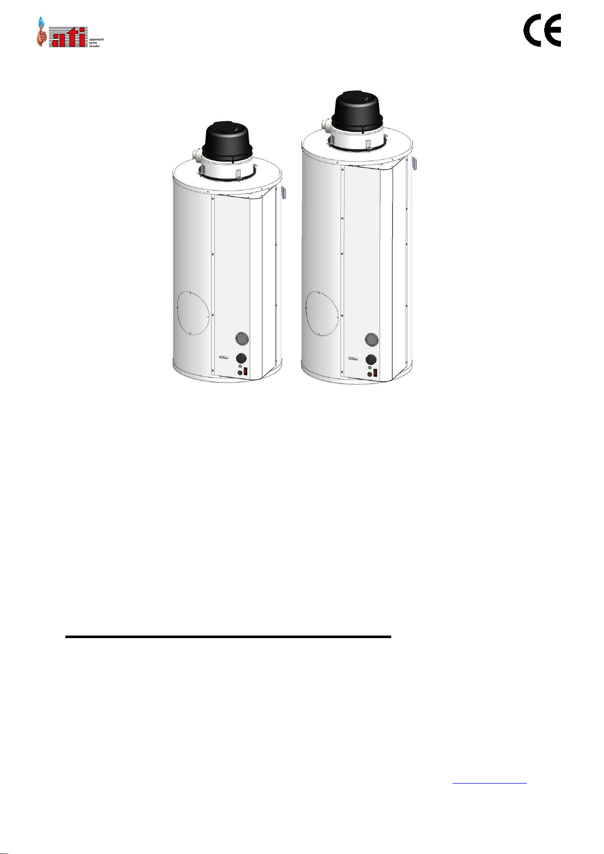
gas generator
hot water
accumulation
with sealed combustion chamber (type C)
and forced draft
INSTRUCTION MANUAL
GENERAL INFORMATION AND FEATURES
INSTALLATION INSTRUCTIONS
INSTRUCTIONS FOR THE USER
original instructions
Read and follow these instructions before installing the unit.
Always keep at hand this manual during the maintenance phase.
This manual is also available in electronic format and can be downloaded from the website www.atimariani.it
SX080 SX120
210-0184_Libretto_SX-080-120_ATI_2019-04_ENG.docx ed. 2019-05
ATI DI MARIANI SRL - Via E. Mattei, 461 - Industrial Area No. 4 Torre del Moro - 47522 Cesena (FC) - Italy
Tel .: +39 0547 609711 - Fax: +39 0547 609724 - Web: www.atimariani.it- Email: info@atimariani.it
IVA IT 00281090407 - REA 143693
Page 2

GENERAL INFORMATION AND FEATURES
210-0184_Libretto_SX-080-120_ATI_2019-04_ENG.docx 2 ed. 2019-05
Page 3

GENERAL INFORMATION AND FEATURES
INDEX
1. SYMBOLS IN THE MANUAL ............................................................................. 4
2. GENERAL WARNINGS ..................................................................................... 4
3. TRANSPORTATION, STORAGE AND DISPOSAL OR RECYCLING ........................ 5
4. CONTENT, WEIGHT AND DIMENSIONS OF PACKAGE ...................................... 5
5. CATEGORY AND CLASSIFICATION DEVICE ....................................................... 6
6. TECHNICAL DATA ............................................................................................ 6
7. DIMENSIONS .................................................................................................. 7
8. DESCRIPTION FUNCTIONAL AND CONSTRUCTION ......................................... 8
9. MAIN COMPONENTS ...................................................................................... 8
10. WIRING .......................................................................................................10
11. LOCAL REGULATIONS, AND INSTALLATION OF SAFETY ...............................11
12. INSTALLATION.............................................................................................12
13. POSITIONING APPARATUS ..........................................................................12
14. INSTALLATION COVER SMOKE EXTRACTION ...............................................13
15. EXHAUST FUMES ........................................................................................13
16. HYDRAULIC CONNECTIONS .........................................................................15
17. TRUNK GAS .................................................................................................16
18. GAS POWER TRANSMISSION ......................................................................17
19. ELECTRICAL CONNECTIONS .........................................................................18
20. PUT IN ACTION ...........................................................................................18
21. RECOMMENDATIONS FOR YOU ..................................................................19
22. IGNITION AND TEMPERATURE CONTROL ...................................................19
23. SHUTDOWN ................................................................................................20
24. PERIODIC MAINTENANCE ...........................................................................20
25. POSSIBLE OPERATING FAULTS ....................................................................21
26. VALIDATION OF THE WARRANTY ................................................................21
27. CORRECT DISPOSAL OF THIS PRODUCT ......................................................22
28. FREQUENT QUESTIONS ...............................................................................22
210-0184_Libretto_SX-080-120_ATI_2019-04_ENG.docx 3 ed. 2019-05
Page 4
GENERAL INFORMATION AND FEATURES
DANGER!
serious danger to the life and limb
WARNING!
Possible dangerous situation for the product
and the environment
NOTE!
Tips for users
1. SYMBOLS IN THE MANUAL
In reading this book, particular attention should be given to the parts marked with symbols represented:
2. GENERAL WARNINGS
• this instruction booklet is an integral and essential part of the appliance and must be kept with care
near the appliance for future reference. It contains important information about safety, installation,
use and maintenance.
• any repair of replacement components shall be performed by personnel authorized by the
manufacturer
• the apparatus has been built for the production of hot water: any other type of use is to be
considered as dangerous and unsuitable.
• the appliance must not be installed in damp environments, to be protected from splashes, jets of
water or other liquids, to avoid anomalies to electrical and thermal devices.
• installation must be performed by professionally qualified personnel responsible for complying with
current safety standards. incorrect installation, without complying with the instructions given by
the manufacturer, may cause damage to people, animals or things, for which the manufacturer
assumes no responsibility.
• parts of the packaging (plastic bags, polystyrene, wood, staples, etc.) must not be left within reach
of children as they are potential sources of danger.
• The device can be used by children aged under 8 years old and people with reduced physical,
sensory or mental capabilities, or lack of experience or knowledge, provided under surveillance or
after the companies have received instructions to ' safe use of and understanding of the dangers
inherent in it.
• children should not play with the appliance.
• cleaning and maintenance borne by the user should not be performed by unsupervised children.
• If the appliance should be sold or transferred to another owner, ensure that this booklet
accompanies the same, so that they can be consulted by the new owner and / or installer.
• not to support any kind on the subject. to avoid risk of damage due to freezing, in the case it is
planned to leave the unit unused for a long period in an environment not heated, it is advisable to
empty it completely. The manufacturer is not liable for malfunctions or breakage of components
due to frost and water leakage from the plant.
• to get the best result and the warranty terms, we recommend that you carefully follow the
instructions below and use only original spare parts and kits supplied by the manufacturer.
• multiple devices in the same room for a greater overall thermal capacity 35 kW, constitute thermal
power station and are subject to the provision of the circular n ° 68 VVFF.
• You are not tamper with any device calibrated and sealed at the factory by the manufacturer.
• the devices should be checked and verified regularly by a competent person according to the law of
the country where the equipment is installed.
210-0184_Libretto_SX-080-120_ATI_2019-04_ENG.docx 4 ed. 2019-05
Page 5
GENERAL INFORMATION AND FEATURES
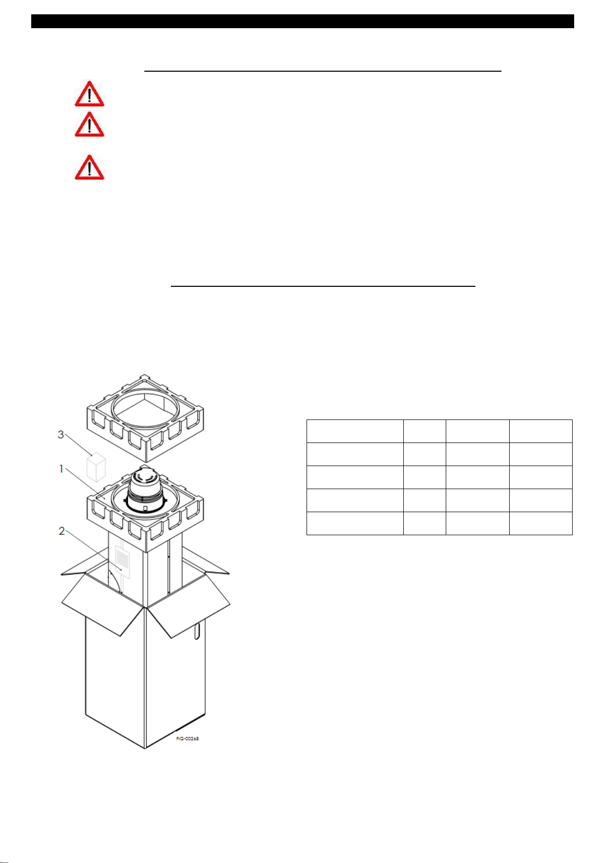
Dimensions and Weights packed unit
SX080
SX120
Width
cm
54
54
Depth
cm
54
54
Height
cm
110
147
Weight
kg
53
78
3. TRANSPORTATION, STORAGE AND DISPOSAL OR RECYCLING
• The appliance must be transported and stored dry and protected from frost.
• The appliance must be stored, transported and used at a temperature between + 10 ° C and + 40 ° C and at a
humidity between 40% and 80%.
• The appliance must not be turned upside down during transport
• Remove the cardboard packaging and polystyrene protections being careful not to damage the appliance. The
European Directive 2002/96 / EC imposes the selective disposal and recycling of electrical and electronic equipment.
The selective disposal, which allows the recycling of the appliance at the end of life and its treatment in respect of the
environment, helps to avoid any adverse effects on the environment and promotes the recycling of materials that make
up the product. Read more about the collection centers of existing waste, please contact your waste collection service
in your municipality of residence or the shop where you purchased the unit.
4. CONTENT, WEIGHT AND DIMENSIONS OF PACKAGE
The generator is delivered packed in cardboard with appropriate protection (1).
Among these it is placed (3) the hydraulic safety group
Inside, over the appliance, there is an envelope (2) containing
• this manual
• the standard warranty certificate
• the LPG conversion kit
210-0184_Libretto_SX-080-120_ATI_2019-04_ENG.docx 5 ed. 2019-05
Page 6

GENERAL INFORMATION AND FEATURES
C12 The air intake and evacuation of
the combustion products takes place
by means of a horizontal coaxial duct
or with openings close enough so that
they can be considered in the same
wind conditions.
C42An apparatus connected to a
collective duct system consists of a duct
for combustion air supply and a conduit
for evacuation of the combustion
products. The orifices of this system are
concentric or close enough to be
exposed to wind conditions comparable.
C32 The air intake and evacuation of
the combustion products takes place
by means of a vertical conduit coaxial.
SX080
SX120
healthcare efficiency class
B
B
Load Profile
M
THE
Nominal tank capacity
the
75
115
nominal heating capacity Q
kW
5.0
5.0
rated thermal power P
KW
4.5
4.3
Gas consumption - natural gas
G20
m3/ h
00:53
00:53
Gas consumption - LPG G30 /
31
kg / h
00:39
00:39
NOx emission value
mg / kWh
26
25
Max water pressure
kPa (bar)
600 (6)
600 (6)
Combustion efficiency
%
95
95
water efficiency
%
89
86
Continuous withdrawal Δ 25 °
c
l / h
153
153
Electrical protection
IP
20
20
Nominal electrical power
W
26
26
electrical characteristics
V / Hz
230 Vac / 50 Hz
The equipment class (according to EN 437) is: IT II2H3B / P G20 - 20 mbar; G30 / 31 - 30/37 mbar
The appliance is classified as: "a hot water gas generator, such accumulation."
These possible exhaust configurations (according to EN 483):
5. CATEGORY AND CLASSIFICATION DEVICE
6. TECHNICAL DATA
210-0184_Libretto_SX-080-120_ATI_2019-04_ENG.docx 6 ed. 2019-05
Page 7
GENERAL INFORMATION AND FEATURES
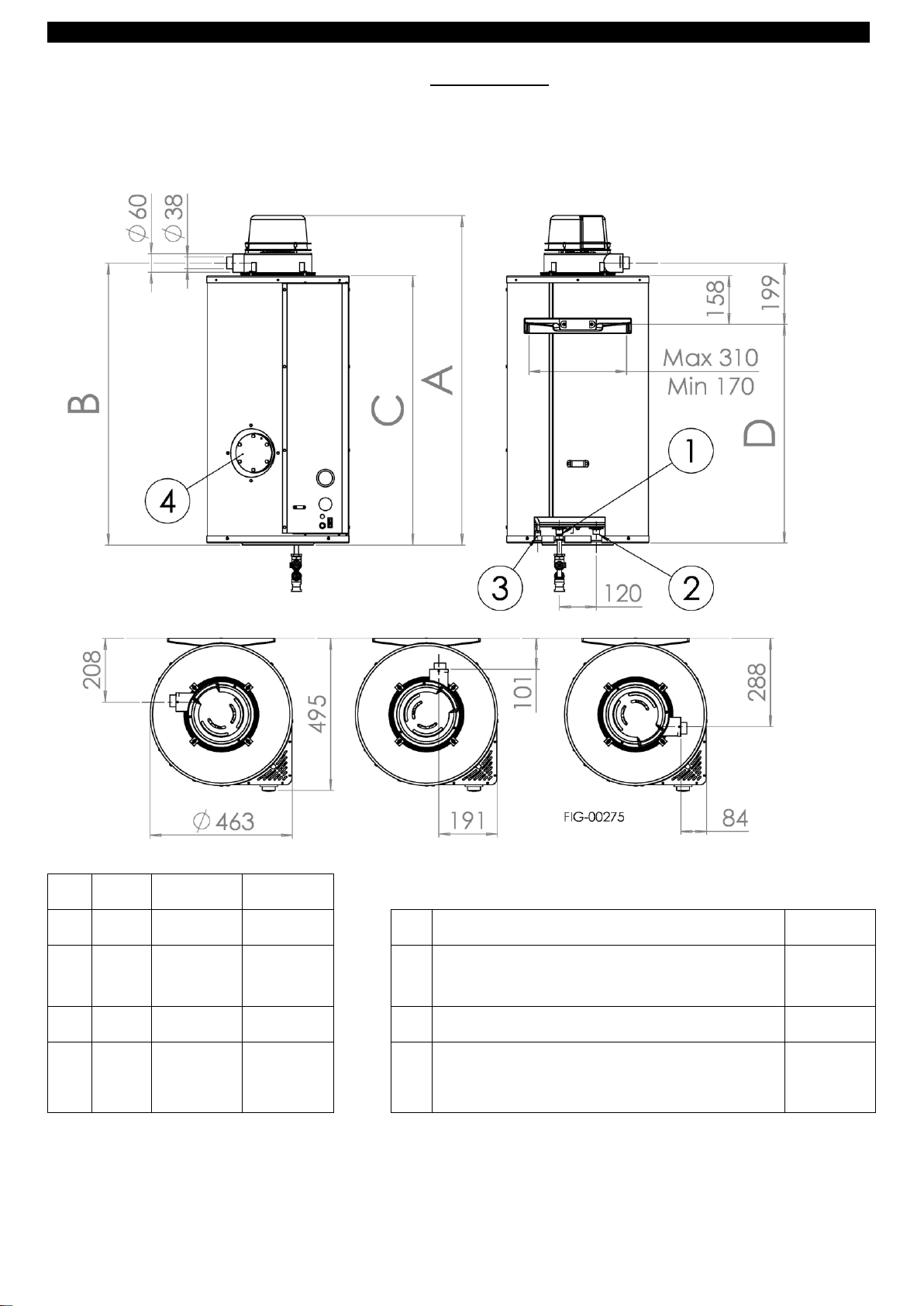
SX080
SX120
A
cm
107
143
1 cold water inlet
1/2 "
B
cm
ninety
two
128
2 hot water outlet
1/2 "
C
cm
88
124
3 gas inlet
3/8 "
D
cm
69
105
4 flange inspection and cleaning
football
Ø 85
7. DIMENSIONS
210-0184_Libretto_SX-080-120_ATI_2019-04_ENG.docx 7 ed. 2019-05
Page 8
GENERAL INFORMATION AND FEATURES
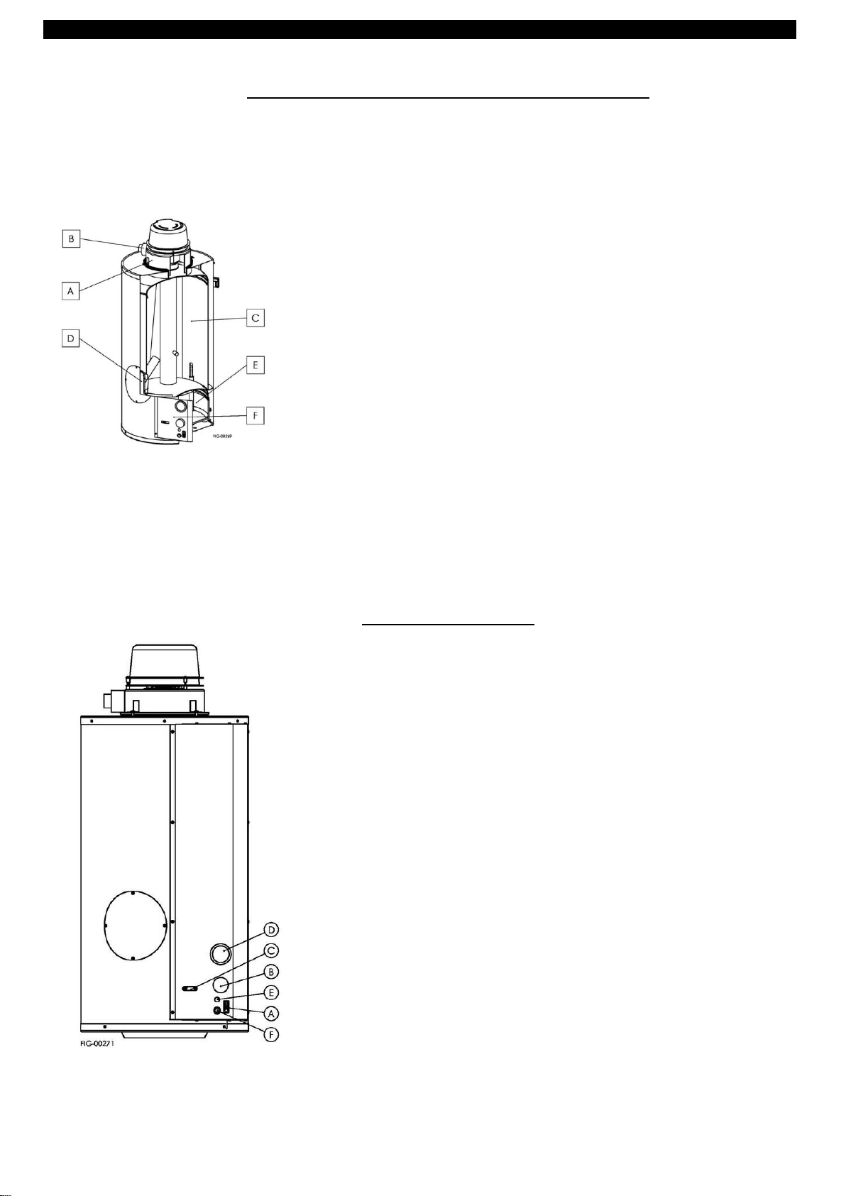
A. Fume extraction hood: a fan located in the top cap provides for the air supply
and evacuation of the combustion products. The cap can be rotated 360 °. In
case of abnormal operation of the fan or obstruction of the ducts, a pressure
cut off the gas flow to the burner.
B. exhaust fumes and air intake
C. boiler: constructed with sturdy sheet and ensures a remarkable resistance to
pressure. It 'also internally subjected to a treatment of cryolite glass or
porcelain enameling, i.e. a glassy coating with firing at over 850 ° C. This allows
to obtain excellent chemical resistance (it is attacked by organic solvents and
many other chemicals), excellent resistance to abrasion (low friction coefficient)
and excellent thermal stability (porcelain enamel on steel resists up to 500 ° C
and also the dry cold and frost do not cause any effect); more generally all that
allows a long service life of the tank and a greater hygiene of the water.
D. inspection and replacement flange anode: allows inspection of the interior of
the tank and the calcium periodic cleaning. Size: Ø 85 mm
E. Combustion chamber located in the lower part of the appliance and contains
the atmospheric burner and the control of flame sensors. The chamber is
completely sealed off from the environment in which the appliance is installed.
F. instrument panel: it contains everything that serves to control and regulate the
normal functioning: regulating thermostat, ignition switch, button unlock bright,
bright operation indicator, thermometer
A. SWITCH: to switch on and off;
B. THERMOSTAT ADJUSTMENT: is used to adjust the internal temperature of
the tank.
C. FLAME INSPECTION HOLE
D. THERMOMETER: Measure the domestic hot water temperature inside the
tank.
E. LIGHT GREEN POWER: note the correct burner ignition. It is activated
when the burner is turned on
F. RED LIGHT BLOCK: indicates a device lock, to unlock, hold down the button
for 3 seconds.
8. DESCRIPTION FUNCTIONAL AND CONSTRUCTION
The function of this device is to generate hot water through the heat exchange between the combustion products of the burner
and the water present in the storage tank.
The combustion takes place in a completely sealed with respect to the device that contains, by withdrawing the air required for
combustion from the outside and discharging the products of combustion itself always outside.
The sealed combustion chamber, is placed in the lower part of the appliance.
9. MAIN COMPONENTS
210-0184_Libretto_SX-080-120_ATI_2019-04_ENG.docx 8 ed. 2019-05
Page 9

GENERAL INFORMATION AND FEATURES
Magnesium anode: The device is protected against corrosion by galvanic
currents from a magnesium anode. In order to prolong the life of the appliance,
this is to be replaced every year. The anode is located in the inspection flange,
placed in the front part of the tank
A. AIR PRESSURE: it is used to verify and monitor the correct operation
of the air blower, placed on top of the appliance.
B. FAN MOTOR
C. ELECTRONIC CONTROL UNIT: is designed to control, manage
electrical devices and appliance gas.
D. CONNECTION CARD: is used to centralize a user control devices with
the controller interface.
E. SAFETY THERMOSTAT: when the device temperature rises above the
maximum threshold, the safety thermostat comes into operation by
blocking the appliance.
F. GAS VALVE: check the gas inlet to the combustion chamber
G. BURNER GAS
210-0184_Libretto_SX-080-120_ATI_2019-04_ENG.docx 9 ed. 2019-05
Page 10

GENERAL INFORMATION AND FEATURES
THE: Line
N: Neutral
THE: Switch
SB: red lock lamp
RESET: reset button
T: Thermostat for temperature adjusting DHW
SA: Power indicator
VG1: valve GAS
TS: Water Safety thermostat
ACC: Ignition electrode
ION: Detection electrode
V: Frequency Ventilator
AP: Air pressure
F1: Fuse 4 A fast type 250 V
F2: Fuse 2 A quick type 250 V
10. WIRING
210-0184_Libretto_SX-080-120_ATI_2019-04_ENG.docx 10 ed. 2019-05
Page 11

INSTALLATION INSTRUCTIONS
11. LOCAL REGULATIONS, AND INSTALLATION OF SAFETY
LOCAL REGULATIONS
In the installation the local regulations must be observed regarding:
Fire fighters
Gas Company
power Company
Office hygiene and health
SAFETY RULES
Do not perform any cleaning or maintenance work without turning off the water heater and interrupting power supply.
E 'absolutely forbidden to operate the water heater with protection of electrical parts or disassembled safety equipment
excluded.
E 'absolutely forbidden to remove or tamper with safety devices.
In case of failure and / or malfunction switch off the appliance, close the gas valve and not groped to repair it but contact an
authorized service center.
In case of fire should be used in powder extinguishants: not direct jets of water directly against the heaters as they may cause
short circuits.
Apply tools and / or equipment manuals and / or electrical proper use, they are in good condition and used properly.
Make sure that ladders and / or any rolling ladders are positioned securely, that are appropriate and that the steps are inta ct
and not slippery, that they are not moved when someone climbs them and ensure someone supervises.
INSTALLATION INSTRUCTIONS
Make sure, for installation and maintenance work at height (generally with higher altitude to two meters), which are used in
scaffolding standards and the space below is free during the eventual fall of tools and objects.
Make sure that, in case of installation and maintenance, the workplace has adequate hygienic conditions with regard to lighting,
aeration and solidity.
Wear during installation and maintenance, clothing and adequate personal protective equipment.
Do not take any action without first ensuring that there are no gas leaks, by special detector.
The installer must be enabled in the installation of heating equipment according to DECREE MINISTGERIALE January 22, 2008, n.
37 and after work must issue the CONFORMITY 'DECLARATION to the customer.
The appliance must be connected to a hot water distribution network compatible with its performance and its power. Make sure
the installation site and any systems to which it must connect the device comply with the current regulations.
Since the C-type unit, this unit can be installed in any type of local, without any limitation on aeration conditions and volume of
the room.
Before each installation, maintenance or repair, remove the power supply. Protecting tubes and external connection cables in
such a way as to prevent them from being damaged.
Do not take any action without a prior assessment of the absence of an open flame or ignition sources.
If you detect a smell of burning, see the smoke out exit from the apparatus, or is felt strong smell of gas, remove the power
supply, close the gas valve, open the windows and notify the authorized service centers nearest
IN ANY SITUATION AND 'WELL ALWAYS REMEMBER THAT COMMON SENSE
It IS THE BEST SECURITY AGAINST ANY AND / OR INJURY.
210-0184_Libretto_SX-080-120_ATI_2019-04_ENG.docx 11 ed. 2019-05
Page 12

INSTALLATION INSTRUCTIONS
The location of the device must be chosen bearing in mind
the maximum length allowed for each type of discharge, as
well as the need to connect the same to the gas and
electric network.
The appliance does not go outdoors installed in damp
environments, to be protected from splashes, jets of water
or other liquids, to avoid anomalies to electrical and
thermal devices.
E 'recommended to place the heater in such a way as to
facilitate the installation and maintenance operations.
Since the C-type unit, this unit can be installed in any type
of local, without any limitation on the conditions of
ventilation and room volume.
Allow above the appliance one of not less than 20 cm space
to allow any maintenance interventions to the cap of fumes
and one below the device not less than 50 cm space
extraction to allow any maintenance to the combustion
chamber
To prevent possible infiltration of water during a
thunderstorm, we recommend a slight downward slope of
the drain pipe and air suction.
12. INSTALLATION
TO AVOID DAMAGE THE TRANSACTION MUST BE CARRIED OUT BY A QUALIFIED
Before installing the appliance, ensure that the nominal supply voltage is 230 V - 50 Hz.
Make sure that the electrical system is adapted to deliver, in addition to the operating current required by the unit, also
the necessary current for powering appliances and equipment already in use.
Make the electrical connections in accordance with national laws and regulations.
Upstream of the unit to provide a single-pole switch with a minimum distance of 3.5 mm contacts.
The installation of the device is divided into 6 distinct phases, listed below, to be followed with attention and respecting the
order.
1. Positioning device
2. fume extraction hood Installation
3. Installing flue
4. Water connections
5. Connection gas circuit
6. Electrical connection
You should always make the grounding of the unit. Check that the power cord is in perfect condition. Under no circumstances
must repair the cable, possibly damaged, with tape or clamps. If the power cord is damaged, it must be replaced by service
agent or a similarly qualified person in order to avoid a hazard.
Incorrect installation can cause damage to people and things for which the manufacturer can not be held responsible.
13. POSITIONING APPARATUS
IMPORTANT: FOLLOW THE EXTENT TO INSTALL NATIONAL STANDARDS.
210-0184_Libretto_SX-080-120_ATI_2019-04_ENG.docx 12 ed. 2019-05
Page 13

INSTALLATION INSTRUCTIONS
To prevent possible infiltration of water during a
thunderstorm, we recommend a slight downward slope of
the drain pipe and air intake
Make sure you have guaranteed the mechanical stability of
the air / flue gas.
The hole for the passage through the wall of the
exhaust pipe and air suction, should not be cemented: the
flue gas must be free to slide through the hole in such a way
that it can subsequently detach. For this purpose you can use
the rosettes cover-wall supplied with the fumes exhaust kit
to cover the empty space of the hole.
In the case of wall drain, you must observe the following minimum
distances for the tailpipes:
A. in box: 600 mm
B. below ventilation opening: 600 mm
C. under the eaves: 300 mm
D. under the balcony: 300 mm
E. from adjacent window: 400 mm
F. from adjacent ventilation opening: 600 mm
G. from pipes or drains: 300 mm
H. from an angle: 300 mm
I. by an indentation: 300 mm
L. from the ground or every footfall area: 400 mm
M. between terminals 2 vertical: 500 mm
N. between terminals 2 horizontal: 500 mm
O. from a front surface facing without openings or terminals
within a radius of 3 m from the fumes outlet: mm 1500
P. as above but with openings: mm 2500
14. INSTALLATION COVER SMOKE EXTRACTION
The upper part of the mantle has four mounting holes for the cover, which allow installations oriented at 90 ° from one another.
If it is necessary an intermediate position proceed as follows:
1. placing the cap on the hot water generator, with the flue outlet and the air inlet in the desired direction
2. pierce the upper mantle with a tip 4 mm, in correspondence with the cap 4 of the mounting brackets
3. screwing without tightening the screws for fastening to the cap.
4. insert the seal between the cap and the skirt, exerting a slight pressure on the side of the same if necessary
5. tighten the screws with moderate force.
15. EXHAUST FUMES
The appliance is to accumulation and sealed combustion chamber, with the combustion chamber downstream fan. The
installation of the exhaust terminals must comply with current regulations, as well as any provisions from local regulations. You
must not convey the flue gases of several devices within the same flue outlet: each device must have its own separate exhaust
duct.
The apparatus is provided with no exhaust kit series. The following table presents the available kits. Use only original kits
supplied by the manufacturer (purchased separately depending on the type of discharge you want to accomplish).
210-0184_Libretto_SX-080-120_ATI_2019-04_ENG.docx 13 ed. 2019-05
Page 14

INSTALLATION INSTRUCTIONS
ASKITSO CODE
DRAIN HORIZONTAL KIT
configuration TYPE C12
The standard kit is 1 mt., And contains:
• 1 coaxial pipe Ø38 / 60
• 1 clamp with gasket Ø60
• 1 clamp with gasket Ø38
• 2 rosettes wall cover
The maximum length is 3 meters. E 'can
be inserted in the flue duct up to 2 bends
at 90 ° (in this case the maximum length
is decremented by 1 meter for each
curve).
To increase the discharge length is
necessary to purchase special extensions.
Available accessories:
CODE DESCRIPTION
ASPC50 coaxial extension Ø38 / 60 0.5
mt
ASPC100 coaxial extension Ø38 / 60
from 1 mt
ASDC609 coaxial bend Ø38 / 60 to 90 °
ASDC604 coaxial bend Ø38 / 60 to 45 °
ASKITSV CODE
VERTICAL EXHAUST KIT
configuration TYPE C32
The standard kit is 1 m and contains:
• 1 Ø38 / 100 vertical terminal (1 mt)
• 1 reduction Ø100 / 60
• 1 extension Ø60 mt from 0:25
• 2 clamps with gasket Ø60
• 2 clamps with gasket Ø38
• 1 coaxial bend Ø38 / 60 to 90 °
The maximum length is 2 meters. You can
not enter into the ear other curves
fumes, in addition to that already present
in the kit.
To increase the discharge length is
necessary to purchase special extensions.
Available accessories:
CODE DESCRIPTION
ASPC50 coaxial extension Ø38 / 60 0.5
mt
ASPC100 coaxial extension Ø38 / 60
from 1 mt
ASKITSS CODE
KIT EXHAUST HORIZONTAL SPLIT
configuration TYPE C82
The standard kit is 1 mt., And contains:
• 1 tube Ø38 1 mt + 1 tube Ø60 1 mt
• 1 T-fitting Ø60 / 60 + 1 90 ° bend Ø38
• 2 clamps with gasket Ø38
• 1 reduction Ø38 / 60 + 1 clamp Ø60
• 1 rosettes wall cover Ø38 + 2 rosettes
wall cover Ø60
• 1 tailpipe fumes Ø60
The maximum length is 6 m. E 'can be
inserted in the flue gas duct up to 5
bends at 90 ° (in this case the maximum
length is decremented by 1 meter for
each curve)
To increase the discharge length is
necessary to purchase special extensions.
Available accessories:
CODE DESCRIPTION
ASCV609 curve Ø 60 - 90 °
ASCV604 curve Ø60 - 45 °
ASCV389 curve Ø38 - 90 °
ASCV384 curve Ø38 - 45 °
ASPR60 extension Ø60 1 mt
ASPR605 Ø60 extension from 0.5 mt
ASPR38 extension Ø38 1 mt
ASPR385 Ø38 extension from 0.5 mt
CODE ASKITSO - KIT EXHAUST HORIZONTAL
for lengths exceeding
2 mt (for mod. 80)
1 mt (for mod. 120)
CODE CODE ASKITSS - KIT EXHAUST HORIZONTAL SPLIT
for lengths exceeding
4 + 4 meters (for both models)
CAUTION: Depending on the length of the exhaust pipes must be removed the ring mounted on the flue gas connection
210-0184_Libretto_SX-080-120_ATI_2019-04_ENG.docx 14 ed. 2019-05
Page 15

INSTALLATION INSTRUCTIONS
The device is protected against corrosion by galvanic currents from a magnesium anode.
In order to prolong the life of the appliance, it is mandatory to replace at least once
every 12 months. The anode is located in the inspection flange, placed in the front part of the
tank
1. cold water inlet (½ "): stopcock
(recommended)
2. filter to remove any impurities, such as sand,
gravel, mud, etc.. (optional)
3. softener (recommended)
4. Pressure reducer for water, if the pressure is
too high (recommended)
5. boiler safety group EN 1487 supplied with the
device (required)
6. expansion vessel suitable for food use, with a
capacity of not less than 5% of the capacity of
the device (required)
7. cold water inlet (½ "): drain cock
(recommended)
8. hot water outlet (½ "): cock (recommended)
16. HYDRAULIC CONNECTIONS
Furthermore, the appliance will last longer if they are met, as provided by D. LGS. February 2, 2001, 31 (implementation
of Directive 98/83 / EC on the quality of water intended for human consumption), the following parameters:
1. Total hardness: between 10 ° F and 25 ° F.
o in the presence of softening or desalination treatment: make sure that the hardness is not adjusted to a value of
less than 10 ° F
o in the presence of water with hardness greater than 25 ° F is advisable to install a water softener
2. PH: comprised between 6 and 8
3. Chloride: max 200 mg / l
4. Conductivity: max. 2500 mS / cm
In the presence of water with different parameters to the above, it should be given special care in the periodic
maintenance of the tank. In particular it must be replaced several times a year the magnesium anode.
HYDRAULIC COMPONENTS TO BE INSTALLED
210-0184_Libretto_SX-080-120_ATI_2019-04_ENG.docx 15 ed. 2019-05
Page 16

INSTALLATION INSTRUCTIONS
G20 gas (H-gas or methane)
inlet pressure: mbar 20
pressure regulation: insert
all'inettore pressure: mbar 11.5
N ° Ø injectors: 1 x Ø 2:00
gas G30 / 31 (LPG or butane / propane)
inlet pressure: 28-30 / 37 mbar
pressure regulation: excluded
N ° Ø injectors: 1 x Ø 1:15
CAUTION: the pressure of the gaseous phase must be reduced. This
operation is achieved by using:
a) a regulator stage I: provides for reducing the gas pressure from
the present value inside the tanks to a value of about 1.5 bar.
b) a controller stage II which provides the further gas pressure
reduction from the value of 1.5 bar to the value of 30 mbar
17. TRUNK GAS
Connect the gas supply line of the thread present on the generator by means of a removable rigid connector. The gas connection
is 3/8 "
It is recommended to mount along the pipe, in the vicinity of the generator and in an easily accessible location, a faucet
interception manual gas.
Check the tightness of the gas pipe and make sure that it has been performed in accordance with regulations on gas
installations.
GAS REGULATION:the device has already been calibrated at the factory to the pressure of the feed gas for which it was
prepared (shown in the label serial number and packaging).
210-0184_Libretto_SX-080-120_ATI_2019-04_ENG.docx 16 ed. 2019-05
Page 17

INSTALLATION INSTRUCTIONS
Gas Switching to natural gas LPG
Passing gas with natural gas LPG
1. Check that the diameter of the injector contained in
the conversion kit is the one corresponding to the LPG
gas (see table in paragraph 17)
2. Close the stopcock gas and remove the power supply
3. Unscrew the nozzle holder C
4. D Unscrew the injector and replace it with the one
contained in the kit. Tighten in order to ensure the gastight
5. Unscrew the valve cap A and tighten the adjusting
screw B placed beneath it and check that the pressure
at the burner is about 28 mbar (use the outlet pressure
and outlet of the valve, after having unscrewed a few
turns the internal screw)
6. Screw the cap A and the inner screw of the pressure
socket E
7. Attach the label contained in the kit on the appliance
(over the one already present) to signal that has been
adjusted for LPG gas G30 / 31
8. Check with appropriate spray the gas seal on the
threads / junctions and on the pressure outlet
For the gas operation LPG it is essential to follow the
instructions of paragraph 18 (regulators I and II stage)
1. Check that the diameter of the injector contained in the
conversion kit is the one corresponding to the methane
gas (see table in paragraph 18)
2. Close the stopcock gas and remove the power supply
3. Unscrew the nozzle holder C
4. D Unscrew the injector and replace it with the one
contained in the kit. Tighten in order to ensure the gastight
5. Unscrew the valve cap A and B acting on the adjusting
screw located under the cap itself, adjust the injector
pressure is about 11.5 mbar (use the outlet pressure and
outlet of the valve, after having unscrewed a few turns
the internal screw).
6. Screw on the valve cap A and the inner screw of the
pressure socket E
7. Attach the label contained in the kit on the appliance
(over the one already present) to signal that has been
adjusted for methane gas G20
8. Check with appropriate spray the gas seal on the threads
/ junctions and on the pressure outlet
18. GAS POWER TRANSMISSION
To change the type of gas supply is necessary to exclusively use the special conversion kit supplied by the manufacturer:
code Description
AKGPLC methane G20 LPG G30 / 31
AKMETC from LPG G30 / G20 31 to methane
The transformation of the gas type of power should only be done by qualified personnel.
IMPORTANT:CHECK THE SEAL OF GAS PIPES, BOLTS AND JOINTS BEFORE TURNING THE APPLIANCE.
WORN SEALS SHOULD NOT be re-used: E 'MUST REPLACE THEM WITH NEW PARTS
210-0184_Libretto_SX-080-120_ATI_2019-04_ENG.docx 17 ed. 2019-05
Page 18

INSTALLATION INSTRUCTIONS
Land
Neutral
Line
green yellow
blue
Brown
19. ELECTRICAL CONNECTIONS
The machine is sold without mains plug: CPU must be mounted to the first installation.
Connect electrically to a power network at 230V-50Hz, single phase, and to an effective grounding. E 'need to perform a
polarized connection. The appliance cable is composed of three distinct colors cables (refer to the table below to identify the
correct polarization).
Connect the power cord of the appliance, taking care to comply with the electrical standards of the country in which the
appliance is installed. If the power cord is damaged, it must be replaced by a technical service center authorized by the
manufacturer, or by a similarly qualified person in order to avoid a hazard.
For the eventual stopping of the appliance, in the feeding of the same network is necessary to provide a disconnect device (not
supplied) with an opening distance of the contacts that allows complete disconnection in the conditions dictated by the
overvoltage category III
LINE AND NEUTRAL PLUG TO BE THE SAME AS LINE AND NEUTRAL THE ELECTRICAL OUTLET.
Riding in the vicinity of the appliance a switch omnipolar general for the eventual stopping of the appliance. This disconnect
device must be incorporated in the supply system in accordance with installation rules. Connect the power cord, making sure to
comply with local electrical codes.
In case of replacement of the electric power cable, use only a cable with the same characteristics (cable H05 VV-F -
3x0.75).
Warning: The device has no protection against the effects caused by lightning.
Before accessing any electrical part of the appliance, remove the power supply using the bipolar switch.
20. PUT IN ACTION
Before turning on the appliance, check that:
the unit is arranged to work with the available gas
the provisions and regulations in force on the installation of these appliances have been observed, especially with regard to
the correct connection of the evacuation duct of the combustion and the gas supply piping products
that the electricity supply is connected, taking into account the polarity of the same (phase and neutral) and which has been
executed connection to an earthed socket in accordance with applicable provisions
that the gas shut-off valves on the meter and in the vicinity of the generator are open
that the water heater is full of water
210-0184_Libretto_SX-080-120_ATI_2019-04_ENG.docx 18 ed. 2019-05
Page 19

INSTRUCTIONS FOR THE USER
1.
21. RECOMMENDATIONS FOR YOU
• Keep this booklet for future reference. The booklet should be kept near the stove.
• For free verify the correct installation of the device, the end user can directly contact one of the closest authorized service
centers.
• All the steps in the space reserved for the installation and maintenance must be performed by qualified and authorized
according to existing regulations. An incorrect installation, caused by not observing the instructions provided by the
manufacturer, may cause damage to people, animals or things, for which the manufacturer assumes no responsibility.
• The device has been built for the production of hot water: any other type of use is to be considered as dangerous and
unsuitable.
• The appliance does not go outdoors installed in damp environments, to be protected from splashes, jets of water or other
liquids, to avoid anomalies to electrical and thermal devices.
• The installation must be performed by professionally qualified personnel responsible for complying with current safety
standards.
• Any packaging components (plastic bags, polystyrene, wood, staples, etc.) Must not be left within reach of children as they
are potential sources of danger.
• Carefully read the instructions and warnings contained in this booklet as they provide important information about safety,
use and maintenance.
• In case the appliance is sold or transferred to another owner, ensure that this booklet accompanies the same, so that they
can be consulted by the new owner and / or installer.
• Do not place any kind on the subject.
• To get the best result and the warranty terms, we recommend that you follow the operating instructions below, to make
regularly the unit checked by qualified personnel and only use original spare parts and kits supplied by the manufacturer.
• It 'not tamper with any device calibrated and sealed at the factory by the manufacturer.
22. IGNITION AND TEMPERATURE CONTROL
1. Press the switch in position "I"
2. Turn the thermostat setting index B on the desired water temperature value
pos. 1 about 37 ° C
pos. 2 about 47 ° C
pos. 3 about 57 ° C
pos. 4 about 67 ° C
pos. 5 about 77 ° C
3. If the set temperature is lower than the domestic hot water temperature inside of the appliance (detectable by the
thermometer D) starts the generator ignition cycle. The depression exerted by the operation of the fume extraction fan
(under proper conditions the state of the combustion circuit) ago closes the differential pressure switch contacts, and the
flame control device starts the pre-ventilation of the combustion chamber (duration of the pre-ventilation : 30 sec.). At the
end of the pre-ventilation phase they are controlled at the same time the opening of the gas valve and the action of the
electrode for the spark ignition of the burner.
4. When the power of the burner the flame must be detected from the special ionization probe within the safety time (10 sec),
otherwise the control equipment must be in lock state (bright red button F lit). This can easily happen in a new plant, where
210-0184_Libretto_SX-080-120_ATI_2019-04_ENG.docx 19 ed. 2019-05
Page 20

INSTRUCTIONS FOR THE USER
it can still be present air in the gas pipe. In this case, wait about a minute, unlock the device by pressing the illuminated
button to start a new ignition cycle. Repeat until the residual air in the gas pipe is not exhausted and the ignition is regular.
5. IMPORTANT: with the exception of the previous case, the ignition of the indicator light of the bright red button F
block generally indicates a failure or a malfunction. We recommend in this case to contact an authorized Service Center.
6. However, if the ignition of the burner is regular turns on the green light And, it starts the step of heating water. The ignition
can also be checked visually through the flame inspection window C
7. The burner will operate until the water temperature set on the thermostat.
IMPORTANT: the lighting of the red light F can be carried out even in the case both intervened limiter safety thermostat,
ie a water overheating has occurred contained in the boiler. In this case it is essential to contact an authorized Service Center.
23. SHUTDOWN
To turn off the generator for a short time
• rotate the control thermostat knob on the minimum value and press the switch to position "0".
To turn off the generator for a long time:
turn the thermostat knob on the minimum value
press the switch to position "0"
disconnect the electrical supply to the appliance at the main switch
close the gas shut-off valve.
in the case is expected to leave the unit unused for a long period in an environment not heated and with the
possibility of frost, it is advisable to empty it completely.
24. PERIODIC MAINTENANCE
To ensure the safety and prolong its life, you should have it checked at least once a year by an authorized service center,
which will act as follows:
replacing the magnesium anode
internal inspection of the boiler and possible calcium deposited on the bottom cleaning
verification of the gas pipe sealing
burner maintenance
210-0184_Libretto_SX-080-120_ATI_2019-04_ENG.docx 20 ed. 2019-05
Page 21

INSTRUCTIONS FOR THE USER
25. POSSIBLE OPERATING FAULTS
Possible replacements of components shall be performed by personnel authorized by the manufacturer
The control device will lock out without controlling the ignition.
the control apparatus flame detection circuit is faulty and the control self-test does not allow the continuation of the
cycle
the flame detection electrode has a leakage to ground
At the end of the pre-ventilation phase, the ignition electrode does not spark and the control device will lock out.
the ignition transformer is faulty
the electrode connection of power to the terminal apparatus is interrupted
At the end of prepurge the ignition electrode gives spark, but the flame is not formed and the apparatus goes into block.
It lacks the feed gas or air is present inside the pipe
the gas valve does not open because the coils are malfunctioning or their electrical connection is interrupted
At the end of prepurge the ignition electrode gives spark, the flame is formed, but the device will lock.
the flame does not stabilize properly for lack of gas pressure
the detection electrode is not correctly positioned and is not in contact with the flame
the detection electrode electric connection is interrupted
The device will lock during normal operation.
the gas supply has been interrupted, even if at the moment: the equipment, not by detecting the presence of flame,
has gone in block
It has occurred, during an intermittent operation cycle, one of the cases of the previous point.
The generator runs for short intermittent periods, even if the thermostat is working properly and is in heat demand position.
the regulating thermostat is defective and does not properly reveals the water temperature
the pressure switch stops the burner because the flow rate of the fan is not correct, due to obstruction of the ducts or
excessive length of the same.
The control apparatus is not blocking but the cycle remains in preventi lazione.
the differential pressure does not give consent to continue the cycle because the fume extraction ducts or air intake are
clogged
the pressure switch does not give consent to continue the cycle because the fan does not operate and does not exert
sufficient pressure
the differential pressure does not give consent because it is faulty or its electrical connection is interrupted
the differential pressure does not give consent because the tube of the pressure outlet is obstructed or the silicone
hose is disconnected or broken.
The control apparatus is not blocking but the cycle does not start.
during the initial part of the apparatus occurs by the pressure switch contacts have been found in the closed position
(because glued or effect of incorrect calibration of the pressure switch itself) and consequently is not given the consent
to the continuation of the cycle
check if it jumped the printed circuit fuse
26. VALIDATION OF THE WARRANTY
The warranty begins on the date of purchase proven by a document valid for tax purposes (invoice or receipt), considered
essential for the enjoyment of the right to the guarantee.
For further details regarding the terms of the warranty, see the warranty card supplied with your machine. The guarantee
certificate must be stored together with the purchase document (invoice or receipt) and must be performed at authorized
service center staff, in case of a warranty claim. The possession of one device does not give the guarantee.
And 'Do not tamper with any device, set and sealed at the factory by the manufacturer.
210-0184_Libretto_SX-080-120_ATI_2019-04_ENG.docx 21 ed. 2019-05
Page 22

INSTRUCTIONS FOR THE USER
PRODUCT IN COMPLIANCE WITH EU DIRECTIVE 2012/19 / EU-D.Lgs.49 / 2014 pursuant to art. 26 of
Legislative Decree 14 March 2014, n. 49 "Implementation of Directive 2012/19 / EU Waste
Electrical and Electronic Equipment (WEEE)" (Applicable in the European Union countries and
countries with separate collection systems)
The marking on the product or its literature indicates that the product should NOT be disposed of
with other household waste at the end of the life cycle. To prevent possible harm to the
environment or human health from uncontrolled waste disposal, the user is encouraged to
separate this from other types of wastes and recycle it responsibly to promote the sustainable
reuse of material resources. Household users should contact either the retailer where you
purchased the product or their local government office, for details on separate collection and
recycling for this type of product. Business users should contact their supplier and check the terms
and conditions of the purchase agreement.
27. CORRECT DISPOSAL OF THIS PRODUCT
.
28. FREQUENT QUESTIONS
1. You can use a cleanser (adddolcitore, water softener, etc.)?The use of the purifier reduces the protective effect of
magnesium anode and consequently the duration of life of the boiler. The manufacturer recommends not soften the
water to a hardness of less than 10 ° F
2. What is an anode and what is it?The magnesium anode protects the appliance from corrosion due to electric currents
present in the water. The anode, consumed, avoids that these consume electrical current, discharging to the tank, the
material of which is composed of the inside of the tank (the enamel), ensuring a longer life of the tank itself. In order to
extend the life of the latter, the anode is to be replaced every year.
3. Inside the boiler feel the blows: What are they?Excessive formation of limestone (calcium) in the tank can cause some
shots audible outside the boiler itself. The amount of limestone that is formed inside the tank may depend on several
factors: firstly, the quality of the water distributed in the network, which can have many high hardness values. In addition
a high temperature of hot water storage (the temperature set on the thermostat) accelerates the formation of limestone.
Since the formation of scale is an inevitable phenomenon, we recommend doing a proper maintenance check and clean
the inside of the tank at least once a year by an authorized service center, using the special flange from the tank itself.
210-0184_Libretto_SX-080-120_ATI_2019-04_ENG.docx 22 ed. 2019-05
Page 23

INSTRUCTIONS FOR THE USER
210-0184_Libretto_SX-080-120_ATI_2019-04_ENG.docx 23 ed. 2019-05
Page 24

ATI DI MARIANI SRL
Via E. Mattei, 461
Zona Ind. No. 4 Torre del Moro
47522 Cesena (FC) - ITALY
Tel. 0547 609711 Fax 0547 609724
www.atimariani.it
info@atimariani.it
210-0184_Libretto_SX-080-120_ATI_2019-04_ENG.docx 24 ed. 2019-05
 Loading...