

Page 1
ATI Axially Compliant
Robotic Deburring Tools
Speedeburr™
(Models 9150‑AC‑90 and 9150‑AC‑180)
Product Manual
Document #: 9610-50-1029
Engineered Products for Robotic Productivity
Pinnacle Park • 1031 Goodworth Drive • Apex, NC 27539 USA • Tel: +1.919.772.0115 • Fax: +1.919.772.8259 • www.ati‑ia.com • Email: info@ati‑ia.com
Page 2

Manual, Speedeburr, AC‑90 and 180 Series
Document #9610‑50‑1029‑02
Foreword
CAUTION: This manual describes the function, application, and safety considerations of this
product. This manual must be read and understood before any attempt is made to install or
operate the product, otherwise damage to the product or unsafe conditions may occur.
Information contained in this document is the property of ATI Industrial Automation, Inc. (ATI) and shall not be
reproduced in whole or in part without prior written approval of ATI. The information herein is subject to change without
notice. This manual is periodically revised to reect and incorporate changes made to the product.
The information contained herein is condential and reserved exclusively for the customers and authorized agents of ATI
Industrial Automation and may not be divulged to any third party without prior written consent from ATI. No warranty
including implied warranties is made with regard to accuracy of this document or tness of this device for a particular
application. ATI Industrial Automation shall not be liable for any errors contained in this document or for any incidental
or consequential damages caused thereby. ATI Industrial Automation also reserves the right to make changes to this
manual at any time without prior notice.
ATI assumes no responsibility for any errors or omissions in this document. Users’ critical evaluation of this document is
welcomed.
Copyright by ATI Industrial Automation. All rights reserved.
How to Reach Us
Sale, Service and Information about ATI products:
A TI Industrial Automation
1031 Goodworth Drive
Apex, NC 27539 USA
www.ati‑ia.com
Tel: +1.919.772.0115
Fax: +1.919.772.8259
E‑mail: info@ati‑ia.com
Technical support and questions:
Application Engineering
Tel: +1.919.772.0115, Option 2, Option 2
Fax: +1.919.772.8259
E‑mail: mech_support@ati‑ia.com
Pinnacle Park • 1031 Goodworth Drive • Apex, NC 27539 USA • Tel: +1.919.772.0115 • Fax: +1.919.772.8259 • www.ati‑ia.com • Email: info@ati‑ia.com
2
Page 3

Manual, Speedeburr, AC‑90 and AC‑180 Series
Document #9610‑50‑1029‑02
Table of Contents
Foreword .......................................................................................................................................... 2
Glossary ........................................................................................................................................... 5
1. Safety ......................................................................................................................................... 6
1.1 ExplanationofNotications .........................................................................................................6
1.2 General Safety Guidelines ............................................................................................................6
1.3 Safety Precautions ........................................................................................................................6
2. Product Overview ..................................................................................................................... 7
2.1 FFP ..................................................................................................................................................8
2.2 Technical Description ...................................................................................................................9
2.2.1 Environmental Limitations ..................................................................................................9
2.2.1.1 Operation ............................................................................................................9
2.2.1.2 Storage ...............................................................................................................9
2.2.2 Axial Force/ Compliance Unit Performance .....................................................................10
2.2.3 Air Motor Performance ..................................................................................................... 11
3. Installation .............................................................................................................................. 12
3.1 Protection During Transportation ..............................................................................................12
3.2 Inspection of Condition When Delivered ..................................................................................12
3.3 Unpacking and Handling ............................................................................................................12
3.4 Storage and Preventive Maintenance During Storage .............................................................12
3.5 Mounting Installation ..................................................................................................................13
3.6 Pneumatics ..................................................................................................................................14
4. Operation ................................................................................................................................ 16
4.1 Safety Precautions ......................................................................................................................16
4.2 Normal Operation ........................................................................................................................17
4.2.1 Air Quality .........................................................................................................................17
4.2.2 Lubrication ........................................................................................................................17
4.2.3 Media Selection, Design, and Maintenance .....................................................................17
4.2.4 Deburring Tool Approach Path Should Be Slow and At an Angle .....................................17
4.2.5 No Radial Loading ............................................................................................................17
4.2.6 Program the Robot to Incorporate 50% Compliance Travel of the Tool ........................... 17
4.3 Speedeburr Working Environment ............................................................................................18
4.4 Tool Center Point (TCP) Position ...............................................................................................18
4.5 Programming the Deburring Tool Path .....................................................................................18
4.6 Cutter Operation and Burr Selection .........................................................................................19
4.6.1 Bur Selection ....................................................................................................................19
Pinnacle Park • 1031 Goodworth Drive • Apex, NC 27539 USA • Tel: +1.919.772.0115 • Fax: +1.919.772.8259 • www.ati‑ia.com • Email: info@ati‑ia.com
3
Page 4

Manual, Speedeburr, AC‑90 and 180 Series
Document #9610‑50‑1029‑02
5. Maintenance ............................................................................................................................ 21
5.1 Pneumatics ..................................................................................................................................21
5.2 Lubrication ...................................................................................................................................21
5.3 Bur, FFP, Cylinder, Spline, and Lock Ring Inspection ............................................................. 21
5.4 Overhaul .......................................................................................................................................21
6. Troubleshooting and Service Procedures ...........................................................................22
6.1 Troubleshooting ..........................................................................................................................22
6.2 Service Procedures .....................................................................................................................23
6.2.1 Cleaning, Inspection, and Replacement of the Spline, Cylinder, and Lock Ring ..............23
6.2.2 Bur and FFP Replacement ...............................................................................................25
6.2.3 O‑Ring Replacement for the Air Supply Ports and Tool Flange .......................................27
7. Serviceable Parts ................................................................................................................... 28
7.1 Accessories .................................................................................................................................28
8. Specications ......................................................................................................................... 29
9. Drawings ................................................................................................................................. 30
9.1 AC-90 Speedeburr Customer Drawing ......................................................................................30
9.2 AC-180 Speedeburr Customer Drawing ....................................................................................33
9.3 Pneumatic Diagrams for AC Tools .............................................................................................36
10. Terms and Conditions of Sale ............................................................................................... 38
10.1 Motor Life and Service Interval Statement ................................................................................39
10.1.1 Vane Motor Products ........................................................................................................39
Pinnacle Park • 1031 Goodworth Drive • Apex, NC 27539 USA • Tel: +1.919.772.0115 • Fax: +1.919.772.8259 • www.ati‑ia.com • Email: info@ati‑ia.com
4
Page 5

Manual, Speedeburr, AC‑90 and AC‑180 Series
Document #9610‑50‑1029‑02
Glossary
Term Denition
AC Axially compliant.
Adapter Plate
Air Filter
Bur
Burr Any unwanted, raised protrusion on the workpiece.
Chattering Machine vibrations. The cutting tool bounces as it contact the work surface.
Coalescing Filter Device designed to remove liquid aerosols from the supply air lines.
Collet Gripping device used to hold cutting tools in the spindle.
Compliance
Deburr To remove the burrs from a piece of machined work.
End‑Eector Tool used by the robot to perform a particular function.
FFP
ISO
Positive Displacement A device that captures uid of air and discharges that uid or air at a xed rate.
Positive Stop The tool has contacted a physical limitation and can no longer move.
Regulator
Solenoid Valve Electrically controlled device for switching air supplies on and o.
Speedeburr
Vane‑Type
VG Viscosity Grade.
Device for attaching the deburring tool to either a robot ange or a stationary
mounting surface.
Device for removing contamination from air supply lines. Typically refers to
removal of particulates.
Cutting tool used to remove burrs from the workpiece. Alternatively referred to
as a rotary le, cutter, or bit.
The ability of the spindle to passively move in response to protrusions on or
deviations of the workpiece.
Free ying piston. An assembly that moves within the cylinder and spline in the
deburring tool. The FFP attaches to the bur.
A series of standards that are developed and published by the International
Organization for Standardization (ISO). The standards dene, establish, and
maintain an eective quality assurance system for manufacturing and service
industries.
Device used to set and control the supplied air pressure to lower acceptable
levels.
An ATI series of deburring tools that use a vane‑type motor and a oating
rotary cutting bur for edge‑deburring and chamfering of parts.
A positive displacement air motor design utilizing partitions (vanes) to separate
expansion regions inside a housing.
Pinnacle Park • 1031 Goodworth Drive • Apex, NC 27539 USA • Tel: +1.919.772.0115 • Fax: +1.919.772.8259 • www.ati‑ia.com • Email: info@ati‑ia.com
5
Page 6

Manual, Speedeburr, AC‑90 and 180 Series
Document #9610‑50‑1029‑02
1. Safety
The safety section describes general safety guidelines to be followed with this product, explanations of the
notications found in this manual, and safety precautions that apply to the product. More specic notications are
imbedded within the sections of the manual where they apply.
1.1 ExplanationofNotications
The following notications are specic to the product(s) covered by this manual. It is expected that the user
heed all notications from the robot manufacturer and/or the manufacturers of other components used in the
installation.
DANGER: Notication of information or instructions that if not followed will result in
death or serious injury. The notication provides information about the nature of the
hazardous situation, the consequences of not avoiding the hazard, and the method for
avoiding the situation.
WARNING: Notication of information or instructions that if not followed could result
in death or serious injury. The notication provides information about the nature of the
hazardous situation, the consequences of not avoiding the hazard, and the method for
avoiding the situation.
CAUTION: Notication of information or instructions that if not followed could result
in moderate injury or will cause damage to equipment. The notication provides
information about the nature of the hazardous situation, the consequences of not
avoiding the hazard, and the method for avoiding the situation.
NOTICE: Notication of specic information or instructions about maintaining, operating,
installing, or setting up the product that if not followed could result in damage to equipment. The
notication can emphasize, but is not limited to: specic grease types, best operating practices,
and maintenance tips.
1.2 General Safety Guidelines
Prior to purchase, installation, and operation of the Speedeburr product, the customer should rst read and
understand the operating procedures and information described in this manual. Never use the deburring tool
for any purposes, or in any ways, not explicitly described in this manual. Follow installation instructions and
pneumatic connections as described in this manual.
All pneumatic ttings and tubing must be capable of withstanding the repetitive motions of the application
without failing. The routing of pneumatic lines must minimize the possibility of stress/strain, kinking,
rupture, etc. Failure of critical pneumatic lines to function properly may result in equipment damage.
1.3 Safety Precautions
CAUTION: Do not use spare parts other than ATI spare parts. Use of spare parts not
supplied by ATI can damage equipment and void the warranty. Always use genuine ATI
spare parts.
CAUTION: Do not perform maintenance or repair on the Speedeburr product unless
the tool is safely supported or placed in the tool stand and air has been turned
o. Injury or equipment damage can occur with tool not placed in a tool stand and
air remaining on. Place the tool safely in the tool stand and turn o the air before
performing maintenance or repair on the Speedeburr product.
Pinnacle Park • 1031 Goodworth Drive • Apex, NC 27539 USA • Tel: +1.919.772.0115 • Fax: +1.919.772.8259 • www.ati‑ia.com • Email: info@ati‑ia.com
6
Page 7
Manual, Speedeburr, AC‑90 and AC‑180 Series
Document #9610‑50‑1029‑02
2. Product Overview
The AC deburring tool, which is also known as Speedeburr, is a robust, high‑speed, and lightweight vane‑type
air motor deburring unit with a oating rotary cutting bur for edge‑deburring and chamfering of materials such as
aluminum, plastic, and steel.
The AC deburring tool’s pneumatically controlled, articulated design allows the bur to follow the part prole and
compensate for surface irregularities while maintaining a constant force. This axial force/compliance air supply
system provides increased stiness in the path direction and decreased stiness in the contact force direction, both
of which prevent the tool from chattering.
The AC deburring tool utilizes a rotary cutting bur of tungsten carbide or coated with PCD or CBN. Because the
rotary bur has a 45° cutting angle, compliance is lateral and axial.
Custom adapter plates for mounting to the robot, work bench, or a tool xture are available from ATI. Refer to
Section 9—Drawings for more information.
The AC deburring tools have the following pneumatic ports:
• (1) port for axial force/compliance supply that provides constant force on the bur.
• (1) port for motor air supply.
• (2) port(s) for motor exhaust.
ATI has (2) models of the AC deburring tool: 9150‑AC‑90 and 9150‑AC‑180. Both models are similar except for
the following features:
• On the AC‑90, the motor housing extends perpendicular, at a 90° angle, from the mounting bracket. On the
AC‑180, the motor housing extends linearly, 180°, with the mounting bracket. Refer to Section 9—Drawings.
• On the side of the 90° angled bracket, the AC‑90 has an adjustment screw with which the user can use a
small at‑blade screw to adjust the motor speed. The motor speed can also be adjusted on both models by
adjusting the motor air supply pressure. Refer to Section 4.5—Programming the Deburring Tool Path for
more information.
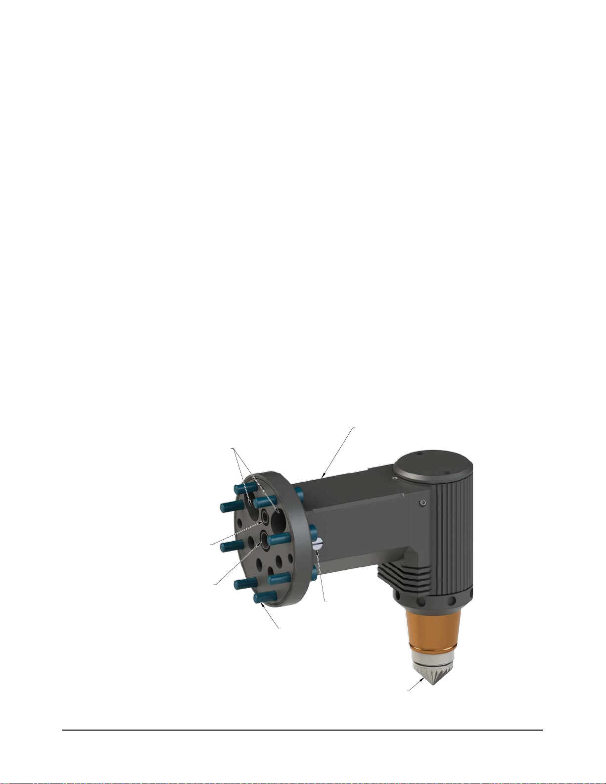
Figure 2.1—AC Deburring Tool (9150-AC-90 Shown)
(2) Motor Exhaust Port
(1) Compliance/
Axial Pressure Air Port
(1) Motor Air
Supply Port
AC Deburring Tool
Adjustment Screw
(8) M4 Socket Head
Cap Screw
Bur
Pinnacle Park • 1031 Goodworth Drive • Apex, NC 27539 USA • Tel: +1.919.772.0115 • Fax: +1.919.772.8259 • www.ati‑ia.com • Email: info@ati‑ia.com
7
Page 8
Manual, Speedeburr, AC‑90 and 180 Series
Document #9610‑50‑1029‑02
2.1 FFP
The FFP is an important component of the AC deburring tool.
A remotely controlled axial force/compliance air pressure pushes the FFP forward into contact with the bur
edge.
Then the air vane motor uncouples from the linear movement of the FFP to reduce inertia and increase the
stability of the contact force during deburring.
Then the spline coupling transmits torque to the bur. Ball bearings within the motor compartment of the tool
ensure the bur operates evenly.
A small amount of frictional torque is transmitted through the ball bearings to the FFP cylinder that rotates
slowly inside the stationary outer cylinder. This small frictional torque prevents stick‑slip or static friction of
the FFP. The FFP cylindrical body is precision grounded to minimize friction in the axial direction.
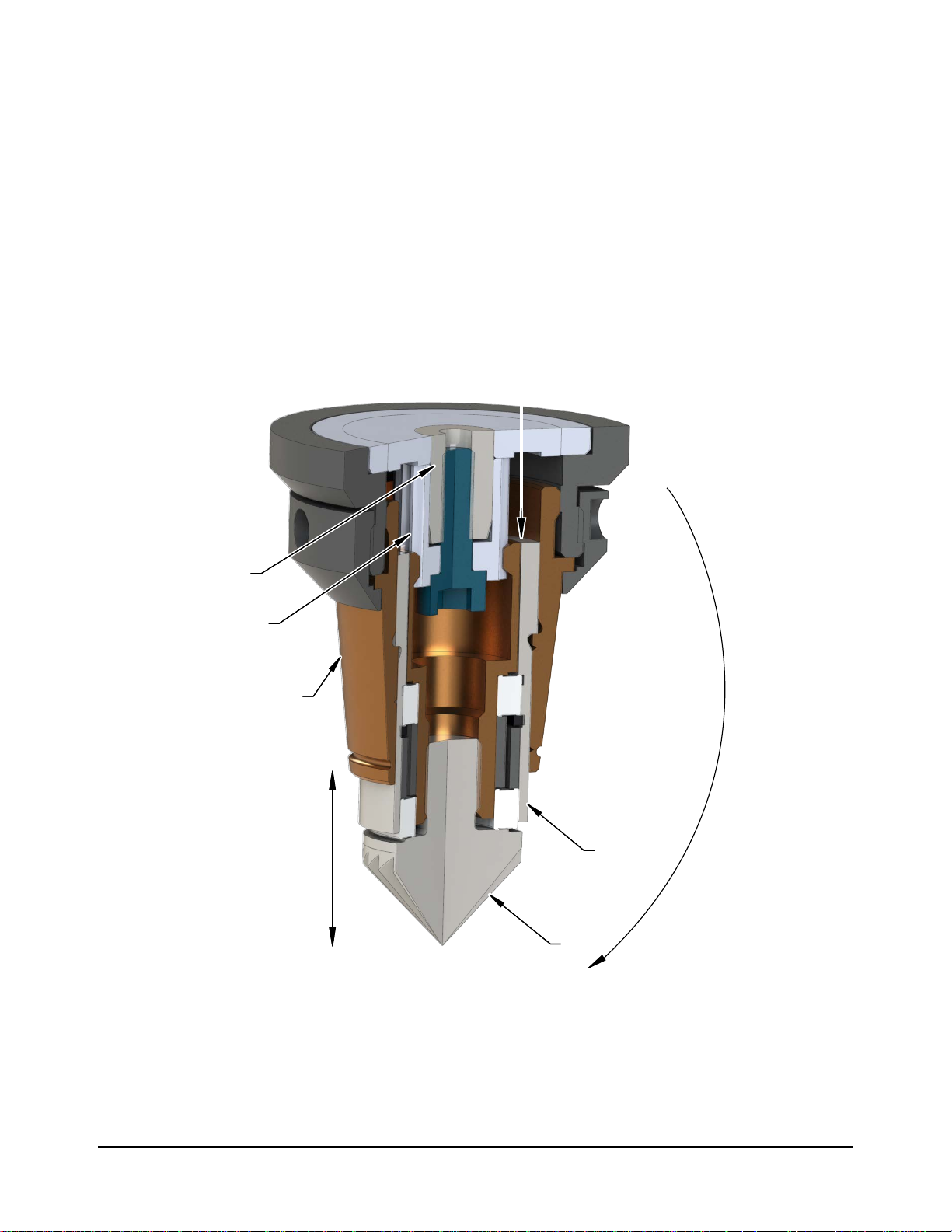
Figure 2.2—FFP (AC-180 Shown)
Air Vane Motor
Spline
Cylinder
Axial Stroke
(0.315”)
8 mm
Axial Force/
Compliance
Pressure
FFP
Bur
Pinnacle Park • 1031 Goodworth Drive • Apex, NC 27539 USA • Tel: +1.919.772.0115 • Fax: +1.919.772.8259 • www.ati‑ia.com • Email: info@ati‑ia.com
8
Page 9

Manual, Speedeburr, AC‑90 and AC‑180 Series
Document #9610‑50‑1029‑02
2.2 Technical Description
A technical overview of the product is provided in the following tables and graph. For additional technical
specications, refer to Section8—Specications.
2.2.1 Environmental Limitations
2.2.1.1 Operation
Table 2.1—Operation
Mounted to robot.
Installation
Position
Temperature
Range
Utilities
Mounted to a table or stand by means of the bench
adapter. The robot is carrying the work piece to the
deburring tool.
5 °C – 35 °C
41 °F – 95 °F
The tool requires the following:
• Clean, dry, ltered, and lubricated air.
• A coalescing lter and lter elements that are rated
5 micron or better.
• Air supply to the spindle must be 6.2 bar (90 psi) to
develop the full rated power.
2.2.1.2 Storage
Temperature
Range
Conditions
• The axial force/compliance air must be supplied at
1.0–4.1 bar (15–60 psi) from a regulated source.
Table 2.2—Storage
0 °C – 45 °C
32 °F – 113 °F
The tool should be stored in its crate and in a dry
place.
When not in use, keep the unit in its crate if possible.
Consult Section 3.4—Storage and Preventive
Maintenance During Storage of this manual.
Pinnacle Park • 1031 Goodworth Drive • Apex, NC 27539 USA • Tel: +1.919.772.0115 • Fax: +1.919.772.8259 • www.ati‑ia.com • Email: info@ati‑ia.com
9
Page 10

Manual, Speedeburr, AC‑90 and 180 Series
Document #9610‑50‑1029‑02
2.2.2 Axial Force/ Compliance Unit Performance
The following graph illustrates the variation of compliance force with applied axial force/
compliance air pressure. Measurements may vary from one product to another and should only be
treated as nominal.
Axial force/compliance is also dependent upon the material of the work piece, type of bur tool, and
the amount of material that is removed.
Figure 2.3—AC Axial Contact Force (measured with the rotary bur pointing down)
Pinnacle Park • 1031 Goodworth Drive • Apex, NC 27539 USA • Tel: +1.919.772.0115 • Fax: +1.919.772.8259 • www.ati‑ia.com • Email: info@ati‑ia.com
10
Page 11
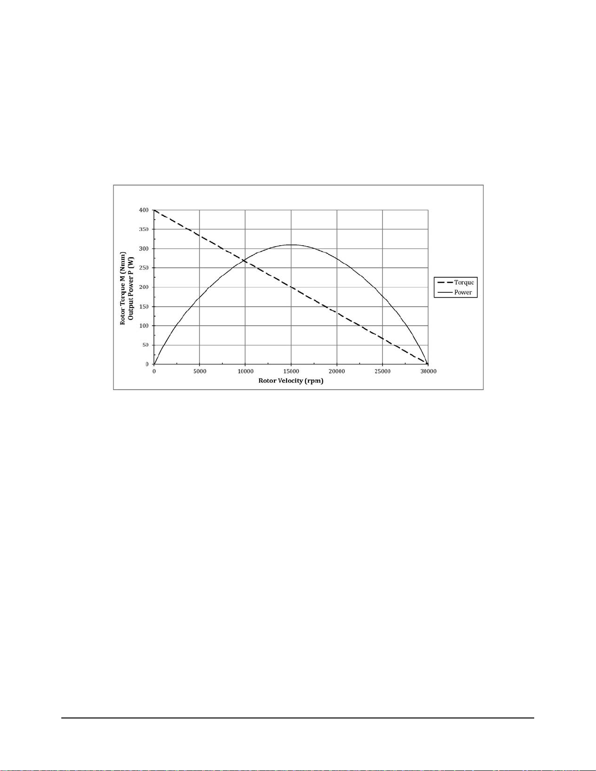
2.2.3 Air Motor Performance
The following graphs illustrate the motor torque and power performance. The air motor operating
speed changes according to the applied load, until the motor develops the power that is required
to perform the specic task. The idle speed of the motor is at maximum, when no load is applied.
Without an applied load, the motor decreases to a slower operating speed at which the motor
develops maximum torque. ATI recommends a working speed of 15,000 to 25,000 RPM for
maximum possible output. The operating speed that is less than 15,000 RPM risks the motor
stalling because of the higher torque at lower speeds.
Figure 2.4—AC Output Torque and Power
Manual, Speedeburr, AC‑90 and AC‑180 Series
Document #9610‑50‑1029‑02
Pinnacle Park • 1031 Goodworth Drive • Apex, NC 27539 USA • Tel: +1.919.772.0115 • Fax: +1.919.772.8259 • www.ati‑ia.com • Email: info@ati‑ia.com
11
Page 12

Manual, Speedeburr, AC‑90 and 180 Series
Document #9610‑50‑1029‑02
3. Installation
The deburring tool is delivered fully assembled. Optional equipment such as mounting adapter plates and bur tools
are separate.
3.1 Protection During Transportation
The deburring tool arrives in packaging that secures and protects the tool during transportation. Always use
this packaging when storing or transporting the deburring tool in order to minimize the risk of damage.
3.2 Inspection of Condition When Delivered
Upon receipt, the following should be checked:
• Delivery in accordance with freight documents.
• Packaging is in good condition.
If there is damage to any of the packaging, or if any of the goods have been exposed to abnormal handling,
unpack those parts that may have been damaged for a closer inspection. If necessary, notify ATI for
assistance in the evaluation of the product condition.
3.3 Unpacking and Handling
The deburring tool should always be placed inside the accompanying packaging, while transporting, storing,
and handling.
Pneumatic lines and cables should be attached, bundled, and strain‑relieved in a manner that allows for
freedom of movement during operation.
3.4 Storage and Preventive Maintenance During Storage
The deburring tool should always be stored in its accompanying packaging, when not in use. The deburring
tool should be stored in a dry place.
For long‑term storage, the deburring tool should be thoroughly cleaned of any burrs or debris. Do not
disassemble the deburring tool. After cleaning, ll the deburring tool with oil of the same type that was used
as a lubrication during operation. Lubrication is necessary to keep the blades in the air‑vane motor from
drying out and prevent corrosion. Place the deburring tool inside a sealed plastic bag. Place the bag with its
contents inside the crate.
Pinnacle Park • 1031 Goodworth Drive • Apex, NC 27539 USA • Tel: +1.919.772.0115 • Fax: +1.919.772.8259 • www.ati‑ia.com • Email: info@ati‑ia.com
12
Page 13
Manual, Speedeburr, AC‑90 and AC‑180 Series
Document #9610‑50‑1029‑02
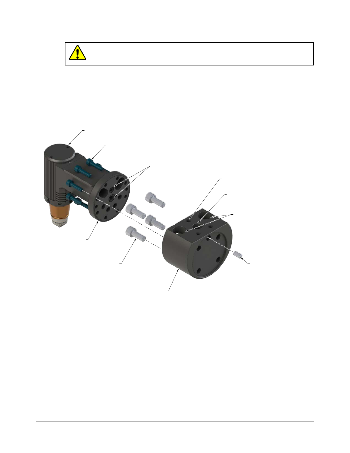
3.5 Mounting Installation
CAUTION: Thread locker applied to fasteners must not be used more than once.
Fasteners might become loose and cause equipment damage. Always apply new
thread locker when reusing fasteners.
The mounting pattern of the AC deburring tool consists of (8) M4 through holes. Refer to the following
gure and Section 9—Drawings. An optional adapter plate allows the deburring tool to attach to a robot
arm, other work surface, or an intermediate adapter plate. Verify the O‑rings are positioned correctly into the
grooves on the deburring tool bracket before mounting the tool to the adapter plate. If the AC deburring tool
is permanently mounted to a work surface, the robot carries the part to be deburred to the deburring tool.
Figure 3.1—Mounting Installation (9150-H/T-3178 Adapter Shown.)
(9150-H/T-3179 is the same but with G (BSPP) ports and a M5 compliance air port.)
AC Deburring Tool
(8) M4 Socket Head
Cap Screw
(2) O-ring
(1) 10-32
Axial Force/Compliance Air Supply Port
Mounting Bracket
(4) M6 Socket Head
(Customer Supplied)
Cap Screw
(1) 1/8 NPT
Motor Air Supply Port
(2) 1/4 NPT
Motor Exhaust
Dowel Pin
(Customer Supplied)
Adapter Plate
(9150-H/T-3178 Shown)
Pinnacle Park • 1031 Goodworth Drive • Apex, NC 27539 USA • Tel: +1.919.772.0115 • Fax: +1.919.772.8259 • www.ati‑ia.com • Email: info@ati‑ia.com
13
Page 14

Manual, Speedeburr, AC‑90 and 180 Series
Document #9610‑50‑1029‑02
3.6 Pneumatics
Conventional, customer‑supplied, pneumatic components are used to control the air supply to the deburring
tool. Consult the valve and regulator supplier’s literature when selecting these components.
Section 9.3—Pneumatic Diagrams for AC Tools shows the (2) connection options for the motor and axial
(compliance) force air supplies:
• Option 1: (1) solenoid valve to control both the motor drive air supply and axial force air supply.
• Option 2: (1) solenoid valve to control the motor air supply and another solenoid valve to control axial
force air supply.
A robot controller actuates the solenoid valves by issuing a digital output signal.
CAUTION: No lubrication causes damage to the motor within a short period of time. If
the motor is not properly lubricated, the motor operates audibly slower than normal and
the speed varies. Ensure the deburring tool is properly lubricated. Install the lubrication
equipment near the robot base and a maximum of (16) feet away from the deburring
tool. Refer to Section 4.2.2—Lubrication for more information.
CAUTION: When the system is rst installed, use a higher oil setting that is
approximately twice the recommended setting. Stay at this setting, until the unit is
receiving consistently oiled air. Run the oil through the entire pneumatic tube between
the oiler and the unit before normal operation.
CAUTION: It is recommended that the customer use a coalescing lter and lter
elements rated 5 micron or better.
ATI recommends that the user install a pneumatic pressure regulator (ATI Part #9150‑FFR‑90, or equivalent)
to achieve a stable air supply of 6.2 bar (90 psi) to the motor. Refer to Section8—Specications for the
maximum ow requirements. Because the deburring motor is a positive displacement device, lower
operating speeds can be achieved by reducing the motor supply air pressure.
Ensure the air lubrication system is lled with oil. Refer to Section 4.2.2—Lubrication for more information.
Use a coalescing lter with elements that are rated for 5 micron or better. An oil recovery unit may be
installed on the exhaust line to avoid the mist lubrication droplets from entering the atmosphere around the
robot installation.
Use a second, precision, self‑relieving regulator (ATI Part # 9150‑P16‑B‑6, or equivalent) for the axial
force/compliance mechanism. Compliance corresponds to the axially applied force on the rotary bur. The
axial force/compliance air supply must be lubricated. Because very little airow is required, a smaller valve
can be used.
If the complete work piece can be deburred with equal force, a conventional, manual pressure regulator can
be used for the axial force/compliance air supply. If the burrs, which are to be removed, vary from place
to place on the work piece, and this variation is repeatable for all work pieces of the same type, it may be
necessary to adjust the force using an analog pressure regulator that is controlled from the robot. An analog
output port in the robot or logic controller will be needed.
The axial force/compliance air supply pressure regulator should have a 1.0‑4.1 bar (15‑60 psi) range. When
testing for the proper contact force, start with a very low pressure and increase slowly until the desired
chamfer is achieved. Typically start at 3 psi (0.21 bar) for aluminum and at a higher pressure for steel
workpieces.
Pinnacle Park • 1031 Goodworth Drive • Apex, NC 27539 USA • Tel: +1.919.772.0115 • Fax: +1.919.772.8259 • www.ati‑ia.com • Email: info@ati‑ia.com
14
Page 15

Manual, Speedeburr, AC‑90 and AC‑180 Series
Document #9610‑50‑1029‑02
WARNING: All pneumatic ttings and tubing must be capable of withstanding the
repetitive motions of the application without failing. The routing of pneumatic lines must
minimize the possibility of over stressing, pullout, or kinking the lines. Failure to do
so can cause some critical pneumatic lines not to function properly and may result in
damage to the equipment.
Table 3.1—Pneumatic Connections
Connection
Function
Adapter
P/N 9150-H/T-3178
Connection Type
P/N 9150-H/T-3179
Adapter
Pressure Requirement
Motor Air Supply 1/8 NPT G 1/8 (BSPP) 90 psi (6.2 bar)
Axial Force/
Compliance Air
Supply
Exhaust
10‑32 M5
Vented to the
atmosphere through
(2) 1/4 NPT ports
Vented to the
atmosphere through
(2) G 1/8 (BSPP)
ports
1.0–4.1 bar
(15–60 psi)
Not Applicable
For the motor air supply, use the largest possible exible plastic tubing or hose that has a 10 mm (3/8”)
minimum inside diameter. For the axial force/compliance air supply, 4 mm (5/32”) outer diameter plastic
tubing is sucient.
To keep the sound level to a minimum mount (2) silencers on the (2) exhaust outlets or route exhaust to
a remote outlet location or oil recovery device. Use a minimum of 13 mm (1/2") diameter plastic tubing.
Always use the largest size exhaust tubing possible with the minimum required length to limit backpressure.
Refer to Section8—Specications for information about the sound level of the deburring tool. The sound
level around deburring equipment cannot be predicted by ATI, because the sound pressure from deburring
operations is process and part dependent. To reduce the sound from the cutting operation in nearby working
areas, a customer‑supplied barrier surrounding the installation may be installed (Plexiglas
®
or Lexan
®
is
preferred).
Pinnacle Park • 1031 Goodworth Drive • Apex, NC 27539 USA • Tel: +1.919.772.0115 • Fax: +1.919.772.8259 • www.ati‑ia.com • Email: info@ati‑ia.com
15
Page 16

Manual, Speedeburr, AC‑90 and 180 Series
Document #9610‑50‑1029‑02
4. Operation
These operating instructions are intended to help system integrators program, start up, and complete a robotic
deburring cell containing a deburring tool. The system integrator should be familiar with the task of deburring and
have extensive knowledge about automation applications that incorporate robots.
4.1 Safety Precautions
DANGER: NEVER use the Speedeburr for purposes other than robotic deburring. If
used in any other way, serious injury or damage to equipment may occur.
DANGER: NEVER use the Speedeburr as a hand‑held machine. If used in this way,
serious injury or damage to equipment will occur.
WARNING: All personnel, who are involved in the operation of the deburring tool,
should have a thorough understanding of the operating procedures. Failure to follow
these procedures or neglecting safety precautions can create hazardous situations that
may injure personnel or damage the deburring installation and the deburring tool.
WARNING: Never operate the Speedeburr product without wearing hearing protection.
High sound levels can occur during cutting. Failure to wear hearing protection can
cause hearing impairment. Always use hearing protection while working in proximity of
the deburring tool.
WARNING: Never operate the Speedeburr product without wearing eye protection.
Flying debris can cause injury. Always use eye protection while working in the
neighborhood of the deburring tool.
CAUTION: Only use burs that are supplied by ATI. Using a bur, which is from another
distributer, is not properly designed for the ATI deburring tool and may cause injury or
damage equipment.
CAUTION: Failure to properly handle the lubrication material and long‑time exposure
to air that contains oil could cause injury to personnel. Refer to the lubrication safety
data sheet (SDS) for more information about the material properties, proper handling/
storage/disposal practices, and what to do in the event of an accidental exposure.
CAUTION: Never be present near the deburring tool while it is started or in operation.
Flying debris and rotating parts can cause injury. If it is necessary to approach the
deburring tool while in motion, stand behind appropriate Plexiglas® or Lexan® windows.
Provide a barrier to prohibit people from approaching the deburring tool while in
operation.
CAUTION: Never use or start the deburring tool without rst reading and understanding
the operating procedures described in this manual. Never use the deburring tool for any
purposes, or in any ways, not explicitly described in this document. Using the deburing
tool without fully understanding the installation and operating procedures may cause
injury to personnel or damage to equipment. Mount the deburring tool and connect the
pneumatic control equipment as described in this manual. Operate the deburring tool
as described in the manual.
CAUTION: Protect the brass cylinder that encloses the FFP from collisions. If struck,
the cylinder may be damaged and need to be replaced in order to continue normal
operations.
Pinnacle Park • 1031 Goodworth Drive • Apex, NC 27539 USA • Tel: +1.919.772.0115 • Fax: +1.919.772.8259 • www.ati‑ia.com • Email: info@ati‑ia.com
16
Page 17

Manual, Speedeburr, AC‑90 and AC‑180 Series
4.2 Normal Operation
The following sections describe the normal operating conditions for the AC deburring tools.
4.2.1 Air Quality
The air supply should be clean, dry, ltered, and lubricated. A coalescing lter that has elements
rated for 5 micron or better is required. The air must be supplied at 6.2 bar (90 psi).
Air quality aects tool performance more than almost any other factor. Particulate can block
airow or impede vane motion. If deburring tools do not receive the proper air pressure, the tool
stalls. Any water in the system damages the housing and blades.
4.2.2 Lubrication
Vane motors for the AC deburring tool must have oil in the motor air supply. Otherwise, the vane
material wears against the housing and degrades quickly. Premature failure results, when using the
deburring tool without lubrication.
Use a brand name air tool oil with a viscosity in the range of IS0 VG 32 to ISO VG 46. For
example, use Mobil™ ALMO OIL 525, which is available from many industrial suppliers.
Do not use oilfog air lubrication systems. Only use microfog systems.
Lubricate the air supply with 3‑4 drops of oil per minute.
The length of the lubrication supply hose between the lubricator and the air motor should be no
more than 5 m (16 feet).
Document #9610‑50‑1029‑02
4.2.3 Media Selection, Design, and Maintenance
Use genuine, proprietary ATI carbide burs.
Check media quality regularly to ensure it is not dull or worn. Using worn media causes poor
surface nish and premature tool failure because of increased wear on the bearings.
Under normal conditions, no cooling or lubrication of the bur is necessary.
4.2.4 Deburring Tool Approach Path Should Be Slow and At an Angle
The deburring tool should approach the workpiece slowly and at an angle.
When beginning a deburring pass, try to minimize the initial impact on the work piece by slowly
approaching the tool at an angle while maintaining a slightly parallel path with the surface.
If the tool quickly approaches perpendicularly to the workpiece, the result is gouging and
premature wear of the tool bearings and results in premature failing of the unit. Additionally,
collisions could result and create a hazardous situation for both personnel and equipment.
4.2.5 No Radial Loading
Do not apply radial loads that are perpendicular to the axis of rotation.
Do not use the AC deburring tool to perform grinding, countersinking, or other metal‑forming
processes.
4.2.6 Program the Robot to Incorporate 50% Compliance Travel of the Tool
Program the robot to have the tool's compliance at 50% travel when on the nominal path.
As the part's edge deviates from the perfect path, the cutting bit can use compliance to follow along
high and low spots without losing contact or hitting the positive stop and gouging.
Do not "bottom out" the compliance and hit the positive stop.
Repeated impacts on the positive stop can damage the compliance mechanism or motor.
Pinnacle Park • 1031 Goodworth Drive • Apex, NC 27539 USA • Tel: +1.919.772.0115 • Fax: +1.919.772.8259 • www.ati‑ia.com • Email: info@ati‑ia.com
17
Page 18

Manual, Speedeburr, AC‑90 and 180 Series
Document #9610‑50‑1029‑02
4.3 Speedeburr Working Environment
As described in previous sections, the AC deburring tool should only be used in conjunction with a robot in
a secured work cell/chamber.
The work cell must be secured by means of barriers to prohibit personnel from entering the cell. A lockable
door should be included as a part of the barrier in order to facilitate access to the cell for authorized
personnel only. The barrier could consist partly or fully of Plexiglas to facilitate observation of the deburring
operations.
During system or deburring tool maintenance, make sure the AC deburring tool and robot are stopped before
entering the robot cell. When installing and testing, never be present in the cell when the deburring tool is
running.
Be aware of rotating parts. Use eye‑protection while working around the deburring tool.
Be aware of high sound levels. Always use hearing protection while working in the proximity of the
deburring cell.
The deburring tool should not be used to deburr materials that are prone to fracture. A fracturing work
piece may result in pieces of material damaging surrounding working environment and personnel. Material
removed correctly should be in the form of chips.
4.4 Tool Center Point (TCP) Position
The overall deburring tool dimensions are shown in Section 9—Drawings. When setting the TCP position
in the robot controller, use the mid‑position of the 8 mm(0.315") axial stroke of the FFP. Also, take into
account the depth of the Speedeburr adapter plate. If an additional interface plate is used to t the adapter to
the robot, this depth must be considered while setting the TCP position.
Table 4.1—Setting the TCP Distance for X, Y, and Z
Conguration
Without the Speedburr
adapter
With the Speedeburr
adapter
74.93 mm
(2.95")
109.98 mm
(4.33")
Distance for AC-90 Distance for AC-180
X Y Z X Y Z
0
‑69.85 mm
(‑2.75")
N/A
4.5 Programming the Deburring Tool Path
The overall deburring tool dimensions are shown in Section 9—Drawings.
While various methods are available to program the robot path, the bur should be nominally at the mid‑point
of its stroke while deburring a part. The bur moves up and down with part and path variation. The method
that is used depends upon the capabilities of the robot and the programmer's preferences.
One programming method is to use the point of the bur as a guide, follow the edge of the part, and then
manually or automatically add osets to the path points to achieve the correct path.
Another programming method is to input into the robot the actual points that are along the path. If this
method is used, make sure that at each point the bur is at its nominal mid‑point when in contact with the part
and that there are no radial forces.
If an application requires the deburring of sharp inner corners, it may be required to use the area of the bur
that is closer to tip. In this case, compensation and cutting surface speed of the deburring tool are reduced.
When rst running the robot program, observe the path with the axial force/compliance air supply turned
o. When increasing the path speed, notice if the path deviates. Verify that at the operational robot path
speed the bur remains near the mid‑point of its axial travel.
Adjust the axial force/compliance air supply as described in Section 3.6—Pneumatics to achieve the correct
sized and even chamfer.
‑114.81 mm
(‑4.52")
‑149.86 mm
(‑5.90")
Pinnacle Park • 1031 Goodworth Drive • Apex, NC 27539 USA • Tel: +1.919.772.0115 • Fax: +1.919.772.8259 • www.ati‑ia.com • Email: info@ati‑ia.com
18
Page 19

Manual, Speedeburr, AC‑90 and AC‑180 Series
Document #9610‑50‑1029‑02
To change the motor speed, adjust the main supply pressure, for example: increasing the pressure, increases
the speed. On the AC‑90, the user can adjust the speed by using a small at‑blade screwdriver to turn the
adjustment screw on the side of the 90° bracket (refer to Figure 2.1). This adjustment varies the ow rate,
for example: clockwise to decrease and counter‑clockwise to increase the ow rate and speed. In most
applications, it is best to adjust the regulator to a maximum pressure 6.2 bar (90 psi) with the adjustment
screw in the full out position, which is approximately ush with the surface.
4.6 Cutter Operation and Burr Selection
To obtain optimal results, the FFP should operate with little friction in the cylinder. Refer to Section 5—
Maintenance for more information.
The deburring tool should not be operated for extensive periods of time with the cutting tip pointing up.
This orientation increases the amount of debris that enters the cylinder and causes premature damage to the
cylinder and FFP. If the deburring tool must be operated in this orientation, then a continuous or regular
burst of high velocity air should be used to blow debris away from the FFP and cylinder to ensure minimal
friction between the components.
The selection of a cutting tool is highly dependent upon the part material and geometry, and the depth of cut.
Please see Section 4.6.1—Bur Selection for a bur and suitable applications.
4.6.1 Bur Selection
ATI can provide guidance in bur selection; however, only experimentation yields the results
desired. The following table may assist in bur selection.
Table 4.2—Bur Selection
Description Application
9150-HIAC-4579-C2
• Tungsten carbide bur, C2
micro‑grain.
• 90° cone shape, 16 mm
(0.63") diameter.
• 20.3 mm (0.8") overall
length.
• 24 teeth, straight utes.
• 3° negative rake angle.
9150-HIAC-4579-C5
• Tungsten carbide bur, C5
micro‑grain.
• 90° cone shape, 16 mm
(0.63") diameter.
• 20.3 mm (0.8") overall
length.
• 24 teeth, straight utes.
• General purpose deburring,
for example: ferrous
materials.
• Deburring alloy steels.
• Increased wear resistance.
• Longer tool life.
• 3° negative rake angle.
Pinnacle Park • 1031 Goodworth Drive • Apex, NC 27539 USA • Tel: +1.919.772.0115 • Fax: +1.919.772.8259 • www.ati‑ia.com • Email: info@ati‑ia.com
19
Page 20

Manual, Speedeburr, AC‑90 and 180 Series
Document #9610‑50‑1029‑02
Table 4.2—Bur Selection
Description Application
9150-HIAC-4153-C5
• Tunsten carbide bur, C5
micro‑grain.
• 90° cone shape, 16 mm
(0.63") diameter.
• 20.3 mm (0.8") overall
length.
• 27 teeth, spiral utes.
• 3° positive rake angle.
9150-43967
• Tungsten carbide bur.
• 90° cone shape, 16 mm
(0.63") diameter.
• 20.3 mm (0.8") overall
length.
• 16 teeth, straight utes,
chip breaker.
• 5° negative rake angle.
9150-HIAC-1010-C2
• Tungsten carbide bur, C2
Micro‑Grain.
• 80° cone shape, 16 mm
(0.63") diameter.
• 24 mm (0.94") overall
length.
• General purpose deburring.
• Improved surface nish on
most materials.
• Deburring reinforced
plastics and composites.
• General purpose deburring
of non‑ferrous materials,
for example: aluminum.
• 24 teeth, straight utes.
• 3° negative rake angle.
Pinnacle Park • 1031 Goodworth Drive • Apex, NC 27539 USA • Tel: +1.919.772.0115 • Fax: +1.919.772.8259 • www.ati‑ia.com • Email: info@ati‑ia.com
20
Page 21

Manual, Speedeburr, AC‑90 and AC‑180 Series
Document #9610‑50‑1029‑02
5. Maintenance
To obtain the best results, the FFP should operate with little friction in the cylinder. At periodic maintenance
intervals remove debris within the cylinder. Keep the outside of the deburring tool clean to ensure proper cooling.
While simple in design, there are few user‑serviceable parts in the assembly. The user is encouraged to return
the unit to ATI for service. Section 6—Troubleshooting and Service Procedures is provided to assist the user in
cleaning, inspecting, and replacing burs, the FFP, cylinder, and pneumatic connection O‑rings.
For all service, it is recommended that the air supply (before the solenoid valves) be disconnected. Drain any
trapped air pressure in the lines. It is suggested that the air supply be “locked out” to prevent accidental operation
of the spindle. During maintenance operations, refer to Section 6—Troubleshooting and Service Procedures for
maintenance instructions. Service and repair parts are identied in Section 7—Serviceable Parts and Section 9—
Drawings.
5.1 Pneumatics
Routinely check the air lines for their general condition and replaced as required. The air lters should
be checked and replaced as required to maintain optimum performance. The life of the lter elements is
dependent on the quality of compressed air at the customer’s facility and therefore cannot be estimated. For
to Section 3.6—Pneumatics for more information about pneumatic connections.
5.2 Lubrication
Ensure the air motor is being lubricated. Refer to Section 4.2.2—Lubrication.
5.3 Bur, FFP, Cylinder, Spline, and Lock Ring Inspection
The bur, FFP, cylinder, spline, and lock ring may wear depending on cut depth, feed rate, and the material
that is being deburred. Inspect these components regularly for wear and refer to Section 6—Troubleshooting
and Service Procedures for symptoms of worn components. If necessary, replace applicable parts. Refer
to Section 6.2.1—Cleaning, Inspection, and Replacement of the Spline, Cylinder, and Lock Ring. Only use
genuine A TI components.
Whenever the bur is replaced, inspect the FFP and cylinder. The FFP should rotate freely by hand in
the cylinder with no binding. If binding is detected, the FFP and cylinder should be replaced. Refer to
Section 6.2—Service Procedures.
5.4 Overhaul
Return the deburring tool to ATI for repairs or overhaul in order to maintain the technical specications and
tool life of the deburring tool. Symptoms of a diminished motor, which doesn't match the specications in
Table 8.1 and that the deburring tool should be overhauled, include but are not limited to the following:
• decreased or stalling motor speed.
• increased air consumption by the motor.
• increased noise during operation.
Refer to Section 6—Troubleshooting for other signs that the deburring tool should be returned to ATI.
Pinnacle Park • 1031 Goodworth Drive • Apex, NC 27539 USA • Tel: +1.919.772.0115 • Fax: +1.919.772.8259 • www.ati‑ia.com • Email: info@ati‑ia.com
21
Page 22

Manual, Speedeburr, AC‑90 and 180 Series
Document #9610‑50‑1029‑02
6. Troubleshooting and Service Procedures
The following section provides troubleshooting information to help diagnose conditions with the product and
service procedures to help resolve these conditions.
6.1 Troubleshooting
Deburring process development is an iterative, learning task. The following table is presented to assist in
solving deburring problems.
Table 6.1—Troubleshooting
Symptom Cause Resolution
Use better grade bur material. Refer to Section 4.6—Cutter
Operation and Burr Selection.
Replace the regulator.
Replace the O‑rings. Refer to Section 6.2.3—O‑Ring Replacement
for the Air Supply Ports and Tool Flange.
Clean components. Replace as necessary. Refer to Section 5.3—
Bur, FFP, Cylinder, Spline, and Lock Ring Inspection and
Section 6.2.2—Bur and FFP Replacement.
Inspect bur if worn, replace. Refer to Section 6.2.2—Bur and FFP
Replacement.
Choose bur that is designed for work material. Refer to
Section 4.6—Cutter Operation and Burr Selection.
Inspect bur. If worn, replace. Refer to Section 6.2.2—Bur and FFP
Replacement..
Choose bur that is designed for work material. Refer to
Section 4.6—Cutter Operation and Burr Selection.
Inspect bur. If worn, replace. Refer to Section 6.2.2—Bur and FFP
Replacement..
Use a bur with less utes. Refer to Section 4.6—Cutter Operation
and Burr Selection.
Bur wear.
Bur breakage.
Unequal compliance.
Poor nish on work
piece.
Bur is chattering
during cut.
Secondary burrs are
created on the work
piece after cut.
Chip packing of bur.
Hard work material.
Too heavy a cut. Decrease the width of cut. Make multiple passes.
Feed rate is too slow. Increase the feed rate.
Too heavy a cut. Decrease the width of cut. Make multiple passes.
Deection at corner. Do not begin the path at a sharp corner.
Impacting the part. Decrease the feed rate at contact. Enter part at an angle.
The regulator is
defective.
The O‑rings on the
mounting bracket of the
deburring tool are worn.
The FFP is not moving
freely in the cylinder.
Feed rate is too fast. Reduce feed rate.
Bur is worn.
Feed rate is too fast. Reduce feed rate.
Lack of rigidity. Increase axial force/ compliance pressure.
Too heavy a cut. Decrease width of cut. Make multiple passes.
Improper bur selection.
The bur is worn.
Incorrect feed rate. Reduce the feed rate.
Too heavy a cut. Decrease width of cut. Make multiple passes.
Improper bur selection.
Bur is worn.
Too heavy a cut. Decrease the width of cut. Make multiple passes.
Not enough chip
clearance.
Pinnacle Park • 1031 Goodworth Drive • Apex, NC 27539 USA • Tel: +1.919.772.0115 • Fax: +1.919.772.8259 • www.ati‑ia.com • Email: info@ati‑ia.com
22
Page 23

Table 6.1—Troubleshooting
Symptom Cause Resolution
The bur stalls.
Not enough or no motor
supply air.
The O‑rings on the rear
ange of the deburring
tool are worn.
The deburring tool is not
properly lubricate.
The FFP is not moving
freely in the cylinder.
Air motor must be
replaced.
Verify the motor supply air regulator is operating at 90 PSI (6.2 Bar),
and check for leaks.
Replace the O‑rings. Refer to Section 6.2.3—O‑Ring Replacement
for the Air Supply Ports and Tool Flange.
Ensure the deburring tool is properly lubricated. Refer to
Section 4.2.2—Lubrication.
Clean components. Replace as necessary. Refer to Section 5.3—
Bur, FFP, Cylinder, Spline, and Lock Ring Inspection.
Contact ATI.
6.2 Service Procedures
The following service procedures provide instructions for component replacement, when the user chooses
to service the unit in the eld. For all service, the user should disconnect the air supply before the solenoid
valves and vent trapped air pressure from the lines. This step prevents accidental operation of the spindle.
CAUTION: Thread locker applied to fasteners must not be used more than once.
Fasteners might become loose and cause equipment damage. Always apply new
thread locker when reusing fasteners.
Manual, Speedeburr, AC‑90 and AC‑180 Series
Document #9610‑50‑1029‑02
CAUTION: During operation of the deburring tool, the bur reaches high temperatures.
Failure to wear proper personal protection equipment or not allowing the bur to cool
could result in serious injury to the user. Be aware that during operation, the bur
becomes very hot, and before removing the bur, take necessary safety precautions to
avoid injury.
6.2.1 Cleaning, Inspection, and Replacement of the Spline, Cylinder, and Lock Ring
Refer to Figure 6.1.
Parts required: Refer to Section 9—Drawings.
Tools required: Hook spanner wrench (P/N 3810‑51‑1004), 3 mm Allen® wrench, torque wrench
Supplies required: Clean rag, mild solvent, same lubrication oil that is used for operational air
lubrication (refer to Section 4.2.2—Lubrication)
1. De‑energize all energized circuits such as air and power.
2. Using the hook spanner wrench, remove the lock ring from the deburring tool housing.
3. Gently remove the cylinder and FFP.
4. Using a mild solvent, clean the spline, interior of the deburring tool housing, and the lock ring.
• If necessary to remove the spline, use a 3 mm Allen wrench to unscrew the M4
socket head cap screw. To re‑install the spline, tighten the M4 socket head cap
screw to 25 in‑lbs (2.825 Nm).
5. Verify the bur and FFP spin together.
a. By keeping the cylinder stationary, verify the FFP and bur spin together. The bur should
move freely.
i. If the bur does not move freely, replace the FFP and/or cylinder. Refer to Section 6.2.2—
Bur and FFP Replacement for replacing the FFP without the bur.
Pinnacle Park • 1031 Goodworth Drive • Apex, NC 27539 USA • Tel: +1.919.772.0115 • Fax: +1.919.772.8259 • www.ati‑ia.com • Email: info@ati‑ia.com
23
Page 24

Manual, Speedeburr, AC‑90 and 180 Series
Document #9610‑50‑1029‑02
6. Inspect and clean the FFP and cylinder.
a. Separate the FFP from the cylinder.
b. Using a clean rag, remove debris from the surfaces of the FFP and cylinder.
c. Inspect the FFP and cylinder for scratches.
i. If the scratches are deep, replace the FFP and Cylinder. For replacement procedures for
the FFP without replacing the bur, refer to Section 6.2.2—Bur and FFP Replacement.
7. Install the cylinder, FFP, and lock ring on the deburring tool.
a. Lightly lubricate the outside diameter of the FFP and the inside diameter of the cylinder.
NOTICE: The t between the FFP and the cylinder provides the seal that is for the axial
down force air pressure. The t must be consistent and without excessive play.
b. Verify the FFP moves freely without excessive play.
i. If the play is excessive, replace the cylinder.
c. Install the cylinder and FFP. The FFP inside diameter interfaces with the outside diameter
on the spline.
d. Using a hook wrench, secure the cylinder and FFP on the deburring tool housing with the
lock ring. Tighten the lock ring hand tight.
8. When the procedure is complete, return to normal operation.
Figure 6.1—Cleaning, Inspection, and Replacement
Deburring Tool
Spline
During reinstallation,
lightly lubricate
the inside diameter
of the cylinder.
During reinstallation,
lightly lubricate
the outside diameter
of the FFP.
(1) M4 Socket Head
Cap Screw
Cylinder
FFP
Hook Wrench
(P/N 3810-51-1004)
Pinnacle Park • 1031 Goodworth Drive • Apex, NC 27539 USA • Tel: +1.919.772.0115 • Fax: +1.919.772.8259 • www.ati‑ia.com • Email: info@ati‑ia.com
Lock Ring
24
Page 25

6.2.2 Bur and FFP Replacement
Refer to Figure 6.2 and Figure 6.3.
Parts required: Refer to Section 9—Drawings.
Tools required: Hook spanner wrench (P/N 3810‑51‑1004), pincer assembly (P/N 9040‑51‑1000),
and holder assembly (P/N 9040‑51‑1001), 5 mm Allen wrench
Supplies required: Clean rag, mild solvent, same lubrication oil that is used for operational air
lubrication (refer to Section 4.2.2—Lubrication)
1. De‑energize all energized circuits such as air and power.
2. Using the hook spanner wrench, remove the lock ring from the deburring tool housing.
3. Remove the bur, FFP, and cylinder.
4. Inspect the FFP and cylinder.
a. Verify the FFP can rotate freely by hand in the cylinder without binding.
i. If binding is detected, replace the FFP and/or cylinder.
5. Gently remove the FFP and bur from the cylinder.
Figure 6.2—Remove the Lock Ring
Manual, Speedeburr, AC‑90 and AC‑180 Series
Document #9610‑50‑1029‑02
Cylinder
FFP
Bur
Lock Ring
Hook Wrench
(P/N 3810-51-1004)
6. Remove the bur from the FFP.
a. Insert the holder assembly into the FFP.
b. Use a 5 mm Allen wrench to loosen the M6 socket head cap screw to open the pincer
assembly so that it ts over the large diameter of the bur.
c. Use a 5 mm Allen wrench to tighten the M6 socket head cap screw to close the pincer
assembly around bur.
d. Holding the FFP stationary with the holder assembly, turn the pincer assembly
counter‑clockwise until the bur is removed from the FFP.
Pinnacle Park • 1031 Goodworth Drive • Apex, NC 27539 USA • Tel: +1.919.772.0115 • Fax: +1.919.772.8259 • www.ati‑ia.com • Email: info@ati‑ia.com
25
Page 26

Manual, Speedeburr, AC‑90 and 180 Series
Document #9610‑50‑1029‑02
Figure 6.3—FFP and Bur Replacement
Pincer Assembly
P/N 9040-51-1001
FFP
Bur
(1) M6 Socket
Head Cap Screw
Holder Assembly
P/N 9040-51-1000
7. Install the new bur in the FFP.
a. Using a 5 mm Allen wrench loosen the M6 socket head cap screw to open the holder
assembly so that it ts over the large diameter of the bur.
b. Use a 5 mm Allen wrench to tighten the M6 socket head screw so that the holder assembly
closes around the bur.
c. If applicable, insert the pincer assembly in the new FFP.
d. Holding the FFP stationary with the pincer assembly, turn the holder assembly clockwise
until the bur is hand tight in the FFP.
8. Install the cylinder, FFP, and lock ring on the deburring tool.
a. Lightly lubricate the outside diameter of the FFP and the inside diameter of the cylinder.
NOTICE: The t between the FFP and the cylinder provides the seal that is for the axial
down force air pressure. The t must be consistent and without excessive play.
b. Verify the FFP moves freely without excessive play.
i. If the play is excessive, replace the cylinder.
c. Install the cylinder and FFP. The FFP inside diameter interfaces with the outside diameter
on the spline.
d. Using a hook wrench, secure the cylinder and FFP on the deburring tool housing with the
lock ring. Tighten the lock ring hand tight.
9. When the procedure is complete, return to normal operation.
Pinnacle Park • 1031 Goodworth Drive • Apex, NC 27539 USA • Tel: +1.919.772.0115 • Fax: +1.919.772.8259 • www.ati‑ia.com • Email: info@ati‑ia.com
26
Page 27

Manual, Speedeburr, AC‑90 and AC‑180 Series
Document #9610‑50‑1029‑02
6.2.3 O-Ring Replacement for the Air Supply Ports and Tool Flange
Refer to Figure 6.4.
Parts required: Refer to Section 9—Drawings.
Tools required: Hook spanner wrench (P/N 3810‑51‑1004), pincer assembly (P/N 9040‑51‑1000),
and holder assembly (P/N 9040‑51‑1001), 5 mm Allen® wrench
Supplies required: Clean rag, Magnalube
1. De‑energize all energized circuits such as air and power.
2. Remove the deburring tool from the robot or work location.
3. If applicable remove the adapter plate from the deburring tool.
4. Remove the following (3) O‑rings: the large O‑ring that is along the edge of the mounting
bracket and the (2) O‑rings for the air supply ports.
5. Clean debris from the deburring tool using compressed air and a clean rag to wipe any grease
from the outer surfaces and O‑ring grooves.
6. Install the following (3) O‑rings dry: the large O‑ring that is along the edge of the mounting
bracket and the (2) O‑rings for the air supply ports.
7. Apply Magnalube to the O‑rings that were installed in the previous step.
8. If applicable, attach the adapter plate to the deburring tool. Refer to Section 3.5—Mounting
Installation.
9. Install the deburring tool on the robot or work location.
10. After the procedure is complete, return to normal operation.
Mounting bracket of the
AC Deburring Tool
Figure 6.4—O-ring Replacement
Axial Force/Compliance
Air Port
Motor Air Supply Port
O-ring for the Axial Force/
Compliance Air Supply Port
(P/N 3410-0001075-01)
O-ring for the Motor Air Supply Port
(P/N 3410-0001076-01)
O-ring
(P/N 3410-0001465-01)
Pinnacle Park • 1031 Goodworth Drive • Apex, NC 27539 USA • Tel: +1.919.772.0115 • Fax: +1.919.772.8259 • www.ati‑ia.com • Email: info@ati‑ia.com
27
Page 28

Manual, Speedeburr, AC‑90 and 180 Series
Document #9610‑50‑1029‑02
7. Serviceable Parts
The serviceable parts for the 9150‑AC‑90 and 9150‑AC‑180 are shown in Section 9—Drawings.
7.1 Accessories
3
5
72
4
1
ITEM NO. QTY PART NUMBER DESCRIPTION
1 1 Refer to Table 4.2 for bur part numbers and descriptions.
2 1 9040‑51‑1001 Bur Tool Holder Assembly
3 1 9040‑51‑1000 Bur Change Tool Pincer Assembly
4 1 3810‑51‑1004 Hooked Spanner Wrench
5 1 9150‑FFR‑90 High‑Flow Filter/Regulator Assembly
6 1 9150‑P16‑B‑G Precision Regulator
7 1
9150‑H/T‑3178 Optional Adapter Plate with NPT Ports
9150‑H/T‑3179 Optional Adapter Plate with G Ports
6
Pinnacle Park • 1031 Goodworth Drive • Apex, NC 27539 USA • Tel: +1.919.772.0115 • Fax: +1.919.772.8259 • www.ati‑ia.com • Email: info@ati‑ia.com
28
Page 29

Manual, Speedeburr, AC‑90 and AC‑180 Series
8. Specications
Table 8.1—Specicationsfor9150‑AC‑90and9150‑AC‑180
Parameter Rating
Motor Air Motor, vane type
Idle Speed 30,000 RPM
Working Speed 18,000 ‑ 25,000 RPM
Torque (at lower speeds) 0.35 Nm (0.295 ft‑lbs)
Power 250 Watts (0.34 hp) @ 20,000 RPM
Weight (total) 0.51 kg (1.124 lb)
Weight of the FFP with bur 0.05 kg (0.11 lb)
Compensation(buroat)
Axial Force
Bur Surface Speed
7.6 ‑ 11 m/sec (25 ‑ 35 ft/s) measured at 8 mm diameter (halfway
Eective Lateral: ± 2 mm (0.08") recommended.
at a supply pressure of 1.0 ‑ 4.1 bar (15 ‑ 60 psi).
Air Consumption Approximately 6.61 l/s (14 CFM)
Bur Type Refer to Table 4.2.
Special Tools Refer to Section 7.1—Accessories.
Sound Pressure Level
Notes:
1. The equivalent continuous weighted sound pressure level.
2. Because the working environment is unknown, it is impossible to predict the noise that will occur during
an operation. The tool may also excite resonant frequencies on equipment to which it is mounted creating
higher sound pressure levels than the unit by itself.
1,2
80 dB No‑Load at a distance of 1.5 meters (5 feet) from the tool.
Axial: ± 4.1 mm (0.16") maximum.
8.45 ‑ 32.92 N (1.9 ‑ 7.4 lb)
between the center tip and outer rim)
Document #9610‑50‑1029‑02
Pinnacle Park • 1031 Goodworth Drive • Apex, NC 27539 USA • Tel: +1.919.772.0115 • Fax: +1.919.772.8259 • www.ati‑ia.com • Email: info@ati‑ia.com
29
Page 30

Manual, Speedeburr, AC‑90 and 180 Series
Document #9610‑50‑1029‑02
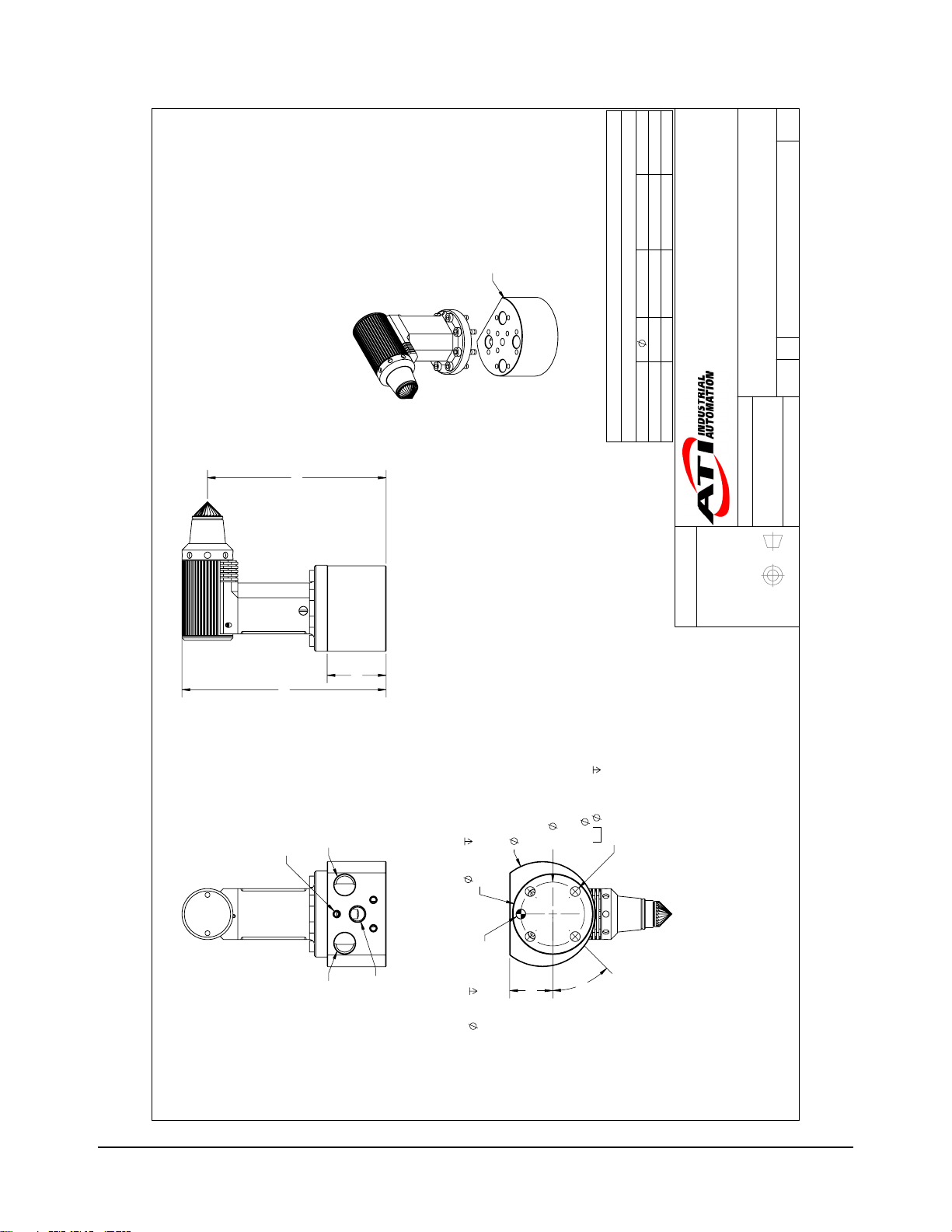
9. Drawings
9.1 AC-90 Speedeburr Customer Drawing
DATE
7/13/2018
INITIATOR
MLS
8 AXIAL
STROKE
DESCRIPTION
ECO 17037; SHEET 2: REMOVED DIAGRAM.
REV.
02
16
BURR (FILE)
TUNGSTEN CARBIDE
DETAIL A
SCALE 2 : 1
AXIAL COMPLIANCE
02
REVISION
ISO 9001 Registered Company
Fax: +1.919.772.8259 www.ati-ia.com
Tel: +1.919.772.0115 Email: info@ati-ia.com
1031 Goodworth Drive, Apex, NC 27539, USA
MANNER EXCEPT ON ORDER OR WITH PRIOR WRITTEN AUTHORIZATION OF ATI.
PROPERTY OF ATI INDUSTRIAL AUTOMATION, INC. NOT TO BE REPRODUCED IN ANY
TITLE
9630-50-AC-90
DRAWING NUMBER
B
SIZE
1:1
SCALE
AC-90 SPEEDEBURR CUSTOMER DRAWING
3
1
SHEET OF
B. ROSE - 6/26/2018
T. BURNS - 7/2/2018
-
PROJECT #
DRAWN BY:
CHECKED BY:
78
86.9 MIN
A
32
75.1
91.1
66.9 MIN
NOTES: UNLESS OTHERWISE
SPECIFIED.
DO NOT SCALE DRAWING.
ALL DIMENSIONS ARE IN
MILLIMETERS.
44
BC
8X M4 X 16 SHCS
EQUALLY SPACED
NOTE 1
22.5°
54
3rd ANGLE PROJECTION
INTERFACE WITH OPTIONAL ADAPTER PLATE, SEE SHEET 3.
RECOMMENDED TORQUE = 25 IN-LBS
Notes:
1.
Pinnacle Park • 1031 Goodworth Drive • Apex, NC 27539 USA • Tel: +1.919.772.0115 • Fax: +1.919.772.8259 • www.ati‑ia.com • Email: info@ati‑ia.com
30
Page 31
112.1
Manual, Speedeburr, AC‑90 and AC‑180 Series
Document #9610‑50‑1029‑02
M5
10-32
Compliance
Motor Exhaust
OPTIONAL ADAPTER
ORDERED SEPARATELY
TABLE 1, NOTE 3
TABLE 1
G 1/8 G 1/4
1/8 NPT 1/4 NPT
Motor Supply
D
66mm
OPTIONAL ADAPTER PLATE DIMENSIONS AND PORT SIZES
Part Number
9150-H/T-3178
ISO 9001 Registered Company
Fax: +1.919.772.8259 www.ati-ia.com
Tel: +1.919.772.0115 Email: info@ati-ia.com
1031 Goodworth Drive, Apex, NC 27539, USA
MANNER EXCEPT ON ORDER OR WITH PRIOR WRITTEN AUTHORIZATION OF ATI.
68.3mm
PROPERTY OF ATI INDUSTRIAL AUTOMATION, INC. NOT TO BE REPRODUCED IN ANY
AC-90 SPEEDEBURR CUSTOMER DRAWING
TITLE
9150-H/T-3179
B. ROSE - 6/26/2018
DRAWN BY:
02
REVISION
9630-50-AC-90
DRAWING NUMBER
B
SIZE
2:3
SCALE
3
2
SHEET OF
T. BURNS - 7/2/2018
-
PROJECT #
CHECKED BY:
37
128.1
MOTOR
PRESSURE
EXHAUST
AIR SUPPLY
COMPLIANCE/AXIAL
MOTOR
EXHAUST
1.4
D
50 H7
INTERFACE
CUSTOMER
6
27
SEE TABLE 1 FOR ADAPTER PORT SIZES
SUPPLY
MOTOR AIR
6 H7
NOTE 2
40
BC
10.490 26.010
6.147 THRU
EQUALLY SPACED
FROM FAR SIDE
4X
45°
NOTES: UNLESS OTHERWISE
SPECIFIED.
DO NOT SCALE DRAWING.
ALL DIMENSIONS ARE IN
MILLIMETERS.
CUSTOMER INTERFACE
NOTE 2
3rd ANGLE PROJECTION
CUSTOMER INTERFACE
Notes:
2. CUSTOMER TO SUPPLY M6 FASTENERS AND DOWEL FOR ADAPTER PLATE MOUNTING.
3. DISCARD (QTY 8) M4 FASTENERS SUPPLIED WITH ADAPTER PLATE.
Pinnacle Park • 1031 Goodworth Drive • Apex, NC 27539 USA • Tel: +1.919.772.0115 • Fax: +1.919.772.8259 • www.ati‑ia.com • Email: info@ati‑ia.com
31
Page 32

Manual, Speedeburr, AC‑90 and 180 Series
Document #9610‑50‑1029‑02
ISO 9001 Registered Company
Fax: +1.919.772.8259 www.ati-ia.com
Tel: +1.919.772.0115 Email: info@ati-ia.com
1031 Goodworth Drive, Apex, NC 27539, USA
Free Flying Piston Assembly, AC
Lock Nut, AC
Cylinder, AC
HIAC Straight Burr, C2 Material
M4-0.7 x 16mm SHCS, Blue, Pre-Applied
O-ring, 50mm ID x 1mm W, Buna-N, 70A Duro
O-Ring 7mm x 1mm, Buna-N 70
O-Ring 5mm x1mm Buna-N D70
DESCRIPTION
02
REVISION
9630-50-AC-90
MANNER EXCEPT ON ORDER OR WITH PRIOR WRITTEN AUTHORIZATION OF ATI.
PROPERTY OF ATI INDUSTRIAL AUTOMATION, INC. NOT TO BE REPRODUCED IN ANY
DRAWING NUMBER
B
SIZE
1:1
SCALE
AC-90 SPEEDEBURR CUSTOMER DRAWING
TITLE
3 3
SHEET OF
B. ROSE - 6/26/2018
T. BURNS - 7/2/2018
-
PART NUMBER
QTY
ITEM NO.
4
1
2
8
4 8
3 1
2 1
1 1
8 1
7 1
6 1
5 1
NOTES: UNLESS OTHERWISE
SPECIFIED.
3
DRAWN BY:
DO NOT SCALE DRAWING.
ALL DIMENSIONS ARE IN
MILLIMETERS.
CHECKED BY:
PROJECT #
3rd ANGLE PROJECTION
9005-51-1000
3700-51-1012
3700-51-1009
3700-50-1003
3500-1062016-15A
3410-0001465-01
3410-0001076-01
3410-0001075-01
9150-AC-90
5
NOTE 4
6
7
SERVICEABLE PARTS
Notes:
4. OTHER BUR OPTIONS AVAILABLE.
Pinnacle Park • 1031 Goodworth Drive • Apex, NC 27539 USA • Tel: +1.919.772.0115 • Fax: +1.919.772.8259 • www.ati‑ia.com • Email: info@ati‑ia.com
32
Page 33
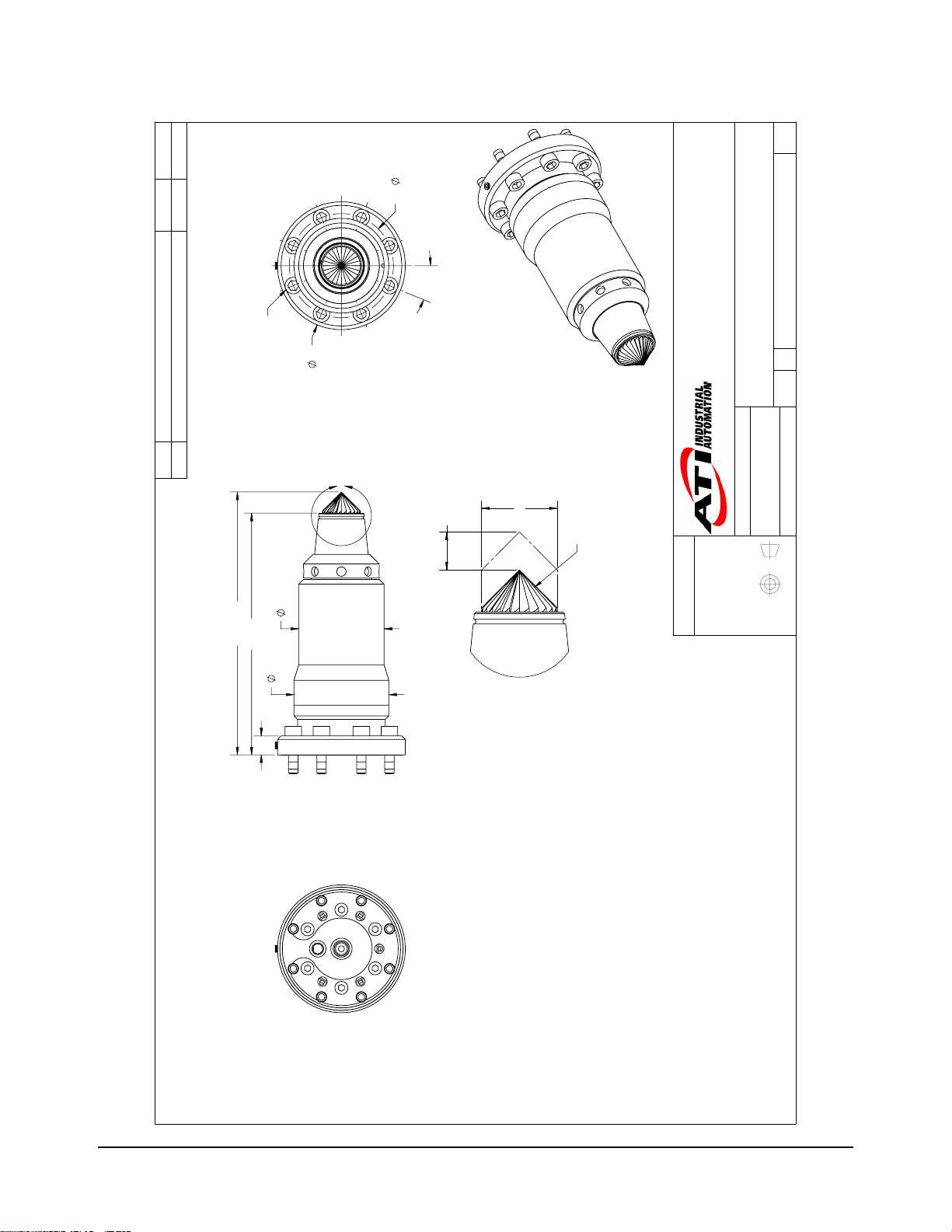
9.2 AC-180 Speedeburr Customer Drawing
DATE
7/13/2018
INITIATOR
MLS
8X M4 X 16 SHCS
EQUALLY SPACED
DESCRIPTION
ECO 17037; SHEET 2: REMOVED DIAGRAM.
REV.
02
NOTE 1
54
A
44
BC
22.5°
8 AXIAL
STROKE
Manual, Speedeburr, AC‑90 and AC‑180 Series
Document #9610‑50‑1029‑02
02
REVISION
ISO 9001 Registered Company
Fax: +1.919.772.8259 www.ati-ia.com
Tel: +1.919.772.0115 Email: info@ati-ia.com
16
BURR (FILE)
TUNGSTEN CARBIDE
1031 Goodworth Drive, Apex, NC 27539, USA
MANNER EXCEPT ON ORDER OR WITH PRIOR WRITTEN AUTHORIZATION OF ATI.
PROPERTY OF ATI INDUSTRIAL AUTOMATION, INC. NOT TO BE REPRODUCED IN ANY
TITLE
B. ROSE - 6/26/2018
DRAWN BY:
9630-50-AC-180
DRAWING NUMBER
B
SIZE
1:1
SCALE
AC-180 SPEEDEBURR CUSTOMER DRAWING
3
1
SHEET OF
T. BURNS - 7/2/2018
-
PROJECT #
CHECKED BY:
111 MIN
102.1
8
36.1
40.1
DETAIL A
SCALE 2 : 1
AXIAL COMPLIANCE
NOTES: UNLESS OTHERWISE
SPECIFIED.
DO NOT SCALE DRAWING.
ALL DIMENSIONS ARE IN
MILLIMETERS.
3rd ANGLE PROJECTION
INTERFACE WITH OPTIONAL ADAPTER PLATE, SEE SHEET 3.
RECOMMENDED TORQUE = 25 IN-LBS
1.
Notes:
Pinnacle Park • 1031 Goodworth Drive • Apex, NC 27539 USA • Tel: +1.919.772.0115 • Fax: +1.919.772.8259 • www.ati‑ia.com • Email: info@ati‑ia.com
33
Page 34

Manual, Speedeburr, AC‑90 and 180 Series
Document #9610‑50‑1029‑02
OPTIONAL ADAPTER
ORDERED SEPARATELY
TABLE 1, NOTE 3
02
M5
10-32
REVISION
Compliance
Motor Exhaust
TABLE 1
G 1/8 G 1/4
1/8 NPT 1/4 NPT
Motor Supply
D
66mm
OPTIONAL ADAPTER PLATE DIMENSIONS AND PORT SIZES
Part Number
9150-H/T-3178
ISO 9001 Registered Company
Fax: +1.919.772.8259 www.ati-ia.com
Tel: +1.919.772.0115 Email: info@ati-ia.com
1031 Goodworth Drive, Apex, NC 27539, USA
MANNER EXCEPT ON ORDER OR WITH PRIOR WRITTEN AUTHORIZATION OF ATI.
68.3mm
PROPERTY OF ATI INDUSTRIAL AUTOMATION, INC. NOT TO BE REPRODUCED IN ANY
TITLE
9150-H/T-3179
B. ROSE - 6/26/2018
9630-50-AC-180
DRAWING NUMBER
B
SIZE
2:3
SCALE
AC-180 SPEEDEBURR CUSTOMER DRAWING
3
2
SHEET OF
T. BURNS - 7/2/2018
-
148
37
MOTOR
27
EXHAUST
SUPPLY
MOTOR AIR
45°
PRESSURE
AIR SUPPLY
COMPLIANCE/AXIAL
SEE TABLE 1 FOR ADAPTER PORT SIZES
MOTOR
EXHAUST
6
6 H7
CUSTOMER INTERFACE
NOTE 2
BC 40
DRAWN BY:
CHECKED BY:
NOTES: UNLESS OTHERWISE
SPECIFIED.
DO NOT SCALE DRAWING.
ALL DIMENSIONS ARE IN
MILLIMETERS.
PROJECT #
3rd ANGLE PROJECTION
D
6.1 THRU
4X
NOTE 2
10.5 26
FROM FAR SIDE
EQUALLY SPACED
CUSTOMER INTERFACE
50 1.4
INTERFACE
CUSTOMER
NOTE 2
Notes:
2. CUSTOMER TO SUPPLY M6 FASTENERS AND DOWEL FOR ADAPTER PLATE MOUNTING.
3. DISCARD (QTY 8) M4 FASTENERS SUPPLIED WITH ADAPTER PLATE.
Pinnacle Park • 1031 Goodworth Drive • Apex, NC 27539 USA • Tel: +1.919.772.0115 • Fax: +1.919.772.8259 • www.ati‑ia.com • Email: info@ati‑ia.com
34
Page 35

Manual, Speedeburr, AC‑90 and AC‑180 Series
Document #9610‑50‑1029‑02
02
REVISION
3
ISO 9001 Registered Company
Fax: +1.919.772.8259 www.ati-ia.com
Tel: +1.919.772.0115 Email: info@ati-ia.com
1031 Goodworth Drive, Apex, NC 27539, USA
MANNER EXCEPT ON ORDER OR WITH PRIOR WRITTEN AUTHORIZATION OF ATI.
2
Free Flying Piston Assembly, AC
Lock Nut, AC
Cylinder, AC
HIAC Straight Burr, C2 Material
M4-0.7 x 16mm SHCS, Blue, Pre-Applied
O-ring, 50mm ID x 1mm W, Buna-N, 70A Duro
O-Ring 7mm x 1mm, Buna-N 70
O-Ring 5mm x1mm Buna-N D70
DESCRIPTION
1
PROPERTY OF ATI INDUSTRIAL AUTOMATION, INC. NOT TO BE REPRODUCED IN ANY
TITLE
B. ROSE - 6/26/2018
9630-50-AC-180
DRAWING NUMBER
B
SIZE
1:1
SCALE
AC-180 SPEEDEBURR CUSTOMER DRAWING
3 3
SHEET OF
T. BURNS - 7/2/2018
-
PART NUMBER
QTY
8
NOTE 4
5
ITEM NO.
1 1
6
2 1
4 8
3 1
7
8 1
7 1
6 1
5 1
NOTES: UNLESS OTHERWISE
SPECIFIED.
4
DO NOT SCALE DRAWING.
ALL DIMENSIONS ARE IN
MILLIMETERS.
DRAWN BY:
CHECKED BY:
PROJECT #
3rd ANGLE PROJECTION
9005-51-1000
3700-51-1012
3700-51-1009
3700-50-1003
3500-1062016-15A
3410-0001465-01
3410-0001076-01
3410-0001075-01
9150-AC-180
SERVICEABLE PARTS
Notes:
4. OTHER BUR OPTIONS AVAILABLE.
Pinnacle Park • 1031 Goodworth Drive • Apex, NC 27539 USA • Tel: +1.919.772.0115 • Fax: +1.919.772.8259 • www.ati‑ia.com • Email: info@ati‑ia.com
35
Page 36

Manual, Speedeburr, AC‑90 and 180 Series
Document #9610‑50‑1029‑02
9.3 Pneumatic Diagrams for AC Tools
DATE
7/9/2018
EXHAUST
INITIATOR
BRR
REVISION
01
DESCRIPTION
INITIAL DRAWING.
REV.
01
AC DEBURRING TOOL
FFP
VANE MOTOR
GAGE
BUR
EXTERNAL
1.0-4.1bar (15-60psi)
PRESSURE REGULATOR
ISO 9001 Registered Company
Fax: +1.919.772.8259 www.ati-ia.com
Tel: +1.919.772.0115 Email: info@ati-ia.com
1031 Goodworth Drive, Apex, NC 27539, USA
AXIAL REACTION FOR
PROPERTY OF ATI INDUSTRIAL AUTOMATION, INC. NOT TO BE REPRODUCED IN ANY
FROM DEBURRING PROCESS
NOTES: UNLESS OTHERWISE
SPECIFIED.
DO NOT SCALE DRAWING.
ALL DIMENSIONS ARE IN
INCHES.
DRAWING NUMBER
MANNER EXCEPT ON ORDER OR WITH PRIOR WRITTEN AUTHORIZATION OF ATI.
SIZE
SCALE
Pneumatic Diagram, AC Tools
TITLE
B. Rose - 7/9/2018
T. Burns - 7/9/2018
DRAWN BY:
CHECKED BY:
9230-50-1071
B
1:1
2
1
SHEET OF
130729-3
PROJECT #
3rd ANGLE PROJECTION
ON/OFF VALVE
ACTUATED FROM
ROBOT CONTROLLER
MIST
LUBRICATOR
FILTER
AIR SUPPLY
6.2bar (90psi)
OPTION 1 (SHEET 1) UTILIZES A SINGLE SOLENOID VALVE TO CONTROL BOTH THE MOTOR DRIVE AND AXIAL FORCE AIR SUPPLY.
OPTION 2 (SHEET 2) UTILIZES TWO SOLENOID VALVES TO SEPARATELY CONTROL THE MOTOR DRIVE AND AXIAL FORCE AIR SUPPLY.
NOTES:
1.
2.
Pinnacle Park • 1031 Goodworth Drive • Apex, NC 27539 USA • Tel: +1.919.772.0115 • Fax: +1.919.772.8259 • www.ati‑ia.com • Email: info@ati‑ia.com
36
Page 37

EXHAUST
Manual, Speedeburr, AC‑90 and AC‑180 Series
Document #9610‑50‑1029‑02
01
REVISION
AC DEBURRING TOOL
ON/OFF VALVE
ACTUATED FROM
ROBOT CONTROLLER
FFP
VANE MOTOR
GAGE
BUR
EXTERNAL
1.0-4.1bar (15-60psi)
PRESSURE REGULATOR
ON/OFF VALVE
ACTUATED FROM
ROBOT CONTROLLER
ISO 9001 Registered Company
Fax: +1.919.772.8259 www.ati-ia.com
Tel: +1.919.772.0115 Email: info@ati-ia.com
1031 Goodworth Drive, Apex, NC 27539, USA
AXIAL REACTION FOR
FROM DEBURRING PROCESS
NOTES: UNLESS OTHERWISE
MANNER EXCEPT ON ORDER OR WITH PRIOR WRITTEN AUTHORIZATION OF ATI.
PROPERTY OF ATI INDUSTRIAL AUTOMATION, INC. NOT TO BE REPRODUCED IN ANY
SPECIFIED.
DO NOT SCALE DRAWING.
ALL DIMENSIONS ARE IN
INCHES.
DRAWING NUMBER
SIZE
SCALE
Pneumatic Diagram, AC Tools
TITLE
B. Rose - 7/9/2018
T. Burns - 7/9/2018
DRAWN BY:
CHECKED BY:
9230-50-1071
B
1:1
2 2
SHEET OF
130729-3
PROJECT #
3rd ANGLE PROJECTION
MIST
LUBRICATOR
FILTER
AIR SUPPLY
6.2bar (90psi)
Pinnacle Park • 1031 Goodworth Drive • Apex, NC 27539 USA • Tel: +1.919.772.0115 • Fax: +1.919.772.8259 • www.ati‑ia.com • Email: info@ati‑ia.com
37
Page 38

Manual, Speedeburr, AC‑90 and 180 Series
Document #9610‑50‑1029‑02
10. Terms and Conditions of Sale
The following Terms and Conditions are a supplement to and include a portion of ATI’s Standard Terms and
Conditions, which are on le at ATI and available upon request.
ATI warrants the compliant tool product will be free from defects in design, materials, and workmanship for
a period of one (1) year from the date of shipment and only when used in compliance with the manufacturer's
specied normal operating conditions. This warranty does not extend to tool components that are subject to wear
and tear under normal usage; including but not limited to those components that require replacement at standard
service intervals. The warranty period for repairs made under a RMA shall be for the duration of the original
warranty, or ninety (90) days from the date of repaired product shipment, whichever is longer. This warranty is void
if the unit is not used in accoACance with guidelines that are presented in this document. ATI will have no liability
under this warranty unless: (a) ATI is given written notice of the claimed defect and a description thereof within
thirty (30) days after the Purchaser discovers the defect and in any event not later than the last day of the warranty
period; and (b) the defective item is received by ATI no later then ten (10) days after the last day of the warranty
period. ATI's entire liability and Purchaser's sole remedy under this warranty is limited to repair or replacement, at
ATI's election, of the defective part or item or, at ATI's election, refund of the price paid for the item. The foregoing
warranty does not apply to any defect or failure resulting from improper installation, operation, maintenance, or
repair by anyone other than ATI.
ATI will in no event be liable for incidental, consequential or special damages of any kind, even if ATI has been
advised of the possibility of such damages. ATI’s aggregate liability will in no event exceed the amount paid by
purchaser for the item which is the subject of claim or dispute. ATI will have no liability of any kind for failure of
any equipment or other items not supplied by ATI.
No action against ATI, regaACless of form, arising out of or in any way connected with products or services
supplied hereunder may be brought more than one (1) year after the cause of action occurred.
No representation or agreement varying or extending the warranty and limitation of remedy provisions contained
herein is authorized by ATI, and may not be relied upon as having been authorized by ATI, unless in writing and
signed by an executive ocer of ATI.
Unless otherwise agreed in writing by ATI, all designs, drawings, data, inventions, software and other technology
made or developed by ATI in the course of providing products and services hereunder, and all rights therein under
any patent, copyright or other law protecting intellectual property, shall be and remain ATI’s property. The sale of
products or services hereunder does not convey any express or implied license under any patent, copyright or other
intellectual property right owned or controlled by ATI, whether relating to the products sold or any other matter,
except for the license expressly granted below.
In the course of supplying products and services hereunder, ATI may provide or disclose to Purchaser condential
and proprietary information of ATI relating to the design, operation or other aspects of ATI’s products. As between
ATI and Purchaser, ownership of such information, including without limitation any computer software provided
to Purchaser by ATI, shall remain in ATI and such information is licensed to Purchaser only for Purchaser’s use in
operating the products supplied by ATI hereunder in Purchaser’s internal business operations.
Without ATI’s prior written permission, Purchaser will not use such information for any other purpose or provide or
otherwise make such information available to any thiAC party. Purchaser agrees to take all reasonable precautions
to prevent any unauthorized use or disclosure of such information.
Purchaser will not be liable hereunder with respect to disclosure or use of information which: (a) is in the public
domain when received from ATI; (b) is thereafter published or otherwise enters the public domain through no fault
of Purchaser; (c) is in Purchaser’s possession prior to receipt from ATI; (d) is lawfully obtained by Purchaser from
a thiAC party entitled to disclose it; or (f) is required to be disclosed by judicial oACer or other governmental
authority, provided that, with respect to such required disclosures, Purchaser gives ATI prior notice thereof and uses
all legally available means to maintain the condentiality of such information.
Pinnacle Park • 1031 Goodworth Drive • Apex, NC 27539 USA • Tel: +1.919.772.0115 • Fax: +1.919.772.8259 • www.ati‑ia.com • Email: info@ati‑ia.com
38
Page 39

Manual, Speedeburr, AC‑90 and AC‑180 Series
Document #9610‑50‑1029‑02
10.1 Motor Life and Service Interval Statement
The air motors that are used in ATI deburring/nishing tools are subject to wear and have a nite life.
Motors that fail, during the warranty period, will be repaired or replaced by ATI as long as there is no
evidence of abuse or neglect and that the normal operating practices outlined in this manual have been
observed.
Components such as motor vanes, bearings, any gear reduction components, and collet nuts/chucks are
considered consumable and are not covered by warranty. The customer should expect to service or replace
these items at designated service intervals. For any part this is not detailed in this manual, contact ATI for
part numbers and pricing.
Premature bearing failure can occur from exposing the deburring tool to coolants and water or impacts from
collisions. Other failure modes that are outlined in the manual and relate to improper machining practices
and deburring media selection.
10.1.1 Vane Motor Products
Vane type motors have a nite life and require regular service. At that time the customer should
expect to replace the motor vanes and bearings. Any gear reduction components should also be
inspected and replaced as necessary. Vane type motors perform best and longest with lubricated air.
The same components will require attention with particular emphasis on replacing the motor vanes.
The expected life of a properly lubricated vane motor in normal operation is entirely application
dependent based on a multitude of factors. To maximize the life of a vane type motor products the
customer should follow closely the normal operation guide in the product manual. The supplied
air must be lubricated, and ltered to remove particulates and moisture. Premature bearing failure
can occur from exposing the deburring tool to coolants and water or impacts from collisions. Other
failure modes are outlined in the manual and relate to improper machining practices and deburring
media selection.
Pinnacle Park • 1031 Goodworth Drive • Apex, NC 27539 USA • Tel: +1.919.772.0115 • Fax: +1.919.772.8259 • www.ati‑ia.com • Email: info@ati‑ia.com
39
 Loading...