

Page 1
www.atiaccess.com
Door Strike
840 N. Old World Third Street, Suite 600 Milwaukee, WI 53203, (414)289-3121, FAX (414) 289-3129
This device complies with part 15 of the FCC Rules.
Operation is subject to the following two conditions: (1)
This device may not cause harmful interference, and (2)
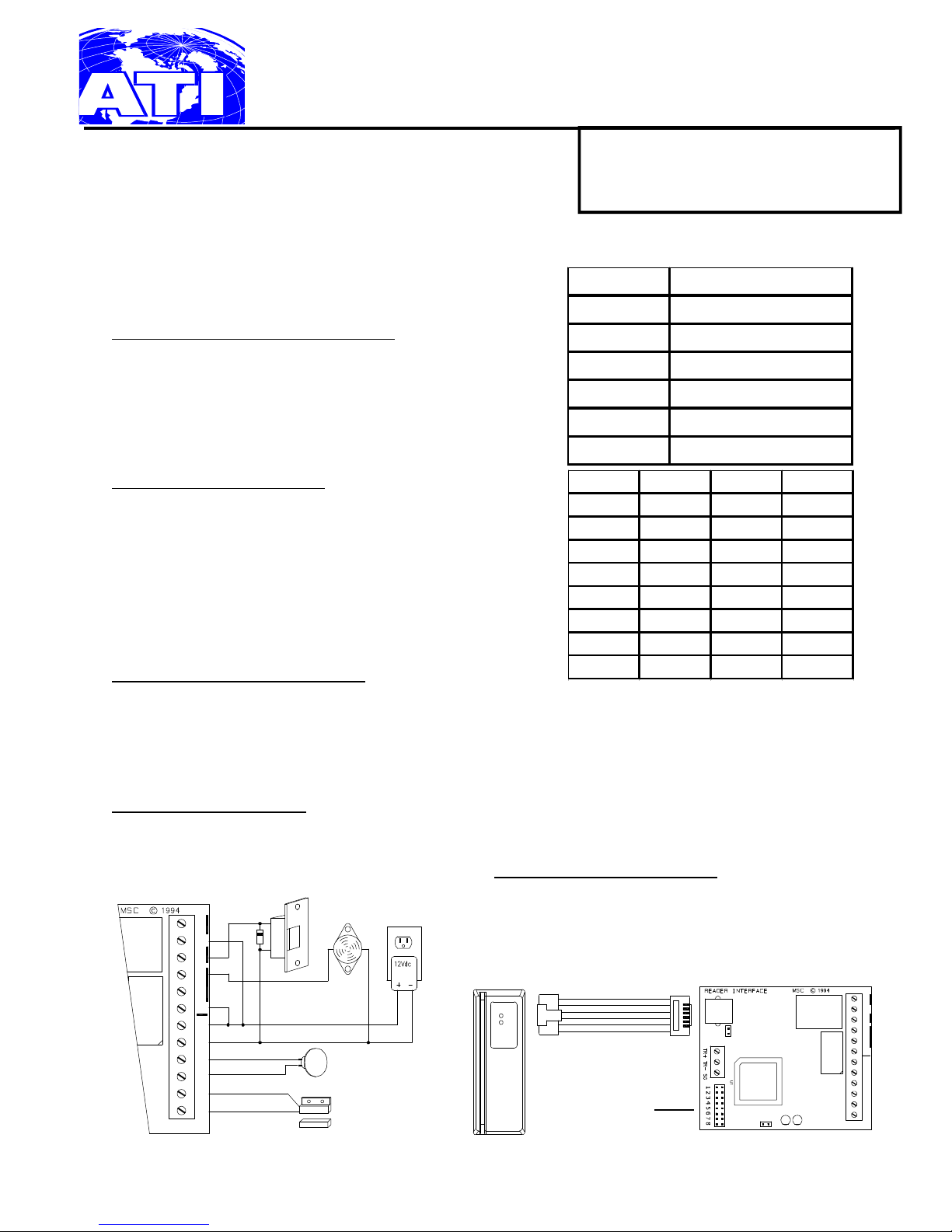
SA-ATM-2 Stand-Alone Access Control System
this device must accept any interference received, including interference that may cause undesired operation.
The SA-ATM-2 is designed to read a specified number of digits from a magnetic stripe card and can
accept up to 100 combinations of those digits.
Setup
Step 1: Decide How Many Digits to Read
The first step is to tell the reader how many digits to read
from the card. This is done by using J2 jumpers 1-3. Using
the table on the right, set J2 jumpers 1-3 to the appropriate
setting. Remove J2 jumpers 1 through 3 for "ATM" mode,
grants access to any card with data on track 2.
J2 Jumper # Description
1-3 Select Number of Digits
4 Strike Relay Duration
5 Not Used
6 Enroll Cards
7 Not Used
8 Delete All Cards
Step 2: Set Door Strike Timing
There are two door strike durations that are selectable by J2
jumper 4. When the J2 jumper 4 is "IN", the strike duration
is 5 seconds. When J2 jumper 4 is "OUT", then the duration
is 1 second.
Jumper 1 Jumper 2 Jumper 3 # of Digits
OUT OUT OUT 0
IN OUT OUT 1
OUT IN OUT 2
IN IN OUT 3
OUT OUT IN 4
Now the reader is ready to accept card information.
Card Maintenance
Enrolling New Card(s) to the System
IN OUT IN 5
OUT IN IN 6
IN IN IN 7
To enroll a new card into the SA-ATM-2, first remove J2 jumper 6. Once removed, the LED on the reader flashes
green. Now swipe each card to be enrolled, the reader will beep two times. When finished enrolling card(s), just
replace J2 jumper 6. The LED on the reader will turn red and the reader will deep three times. The reader is now
ready to be used.
Deleting the Card Database
To delete the cardholder database, just remove power from the unit and install J2 jumper 8. Apply power for 5
seconds and then remove power. Remove J2 jumper 8 and reconnect power. The card database is now
empty. You must then re-enroll your cards.
Reader Configuration Settings
The reader has a four dip switch block which
must be configured. All four switches must be in
NC
K1
C
NO
NO
NC
K2
C
+
12V
GND
I2
I2
I1
I1
Exit Button
Door Contact
the OFF position. When looking into the back of
the reader, all switches should be pushed away.
ATI
J2 Jump-
AB
NC
K1
C
NO
NO
NC
K2
C
+
12V
GND
I2
I2
I1
I1
CONFIDENTIAL: For installation and maintenance use only. DO NOT distribute.
Access Technologies International, Inc.© 2005 SA-ATM-2 Doc. TDM000100 rev. 1.01 07/05 Page 1
Page 2

Installation
Find a suitable location to anchor the reader mounting bracket. The mounting of the reader does not
require a junction box. However, rigid conduit is required for outdoor application. A single gang
junction box may used to provide transition to rigid conduit. If a single gang junction box is used, a
wall plate (optional) may be used to cover the junction box. The reader is then secured to the mounting
bracket using a screw. Refer to figures for reader dimensions and typical junction box usage.
Connect door hardware/power according to the configuration selected. Wires of 22AWG or larger are
recommended for field wiring. See local electrical code.
Coat reader connector with the silicone grease supplied to seal out moisture for outdoor mounting.
To avoid having ESD (electrostatic discharge) interfering with the operation of the reader, the reader
casing shall be grounded. This can be accomplished be tying the mounting bracket to earth ground
locally (e.g. grounded conduit).
Reader Part Number: 36012-0000
Reader DIP switch setting: 4 3 2 1
(Factory Setting) OFF OFF OFF OFF
Relay Contact Protection/Noise Suppression
Load switching can cause contact transfer, welding, and abnormal wear, which can cause premature
contact failure. The switching of an inductive load (strike) can also cause EMI (electromagnetic
interference). To prolong contact life and increase total system reliability, contact protection circuit must
be used. The following two circuits are recommended. For DC application, use a diode circuit; for AC
application, use a MOV (metal oxide varistor) circuit. Locate the protection circuit as close to the load
as possible, as the effectiveness of the circuit will decrease if it is located to far away. As a guideline,
the distance should be within 12 inches (30 cm).
12 VDC
DIODE 1N4001 (50V/1A) TYPICAL
AC XFMR
DC Door Strike
AC Door Strike
DIODE SELECTION:
DIODE CURRENT RATING > 1X STRIKE CURRENT
DIODE BREAK DOWN VOLTAGE : 4X STRIKE VOLTAGE
MOV SELECTION:
FOR 24Vac STRIKE, PANASONIC ERZ-C07DK470
Access Technologies International, Inc.© 2005 SA-ATM-2 Doc. TDM000100 rev. 1.01 07/05 Page 2
VOLTAGE RATING > Vac RMS
Page 3

Additional Information
1. The LED's on the interface board are defined as: A = Heartbeat: 1 second flash, B = Not used, should
be OFF.
2. Output K2 is energized for 1 second when there is a door forced open or door held open alarm. The
door position is monitored by input I1 and the door monitor contact is normally closed. The held
open timer is fixed at 45 seconds.
3. Request-to-exit (REX) input I2: uses a normally open switch. Output K1 is energized as long as the
REX input (I2) is closed.
4. Jumpers J3 and J4 are not used.
Maintenance
The SA-ATM-2 readers are designed to provide continuous service with minimal routine maintenance.
However, contaminants (such as magnetic oxides from badges and dirt) tend to accumulate on the read
head. Without regular cleaning, these contaminants will shorten the read head life and increase the
probability of card read error. A maintenance schedule should be developed base on the card reader
environment (dirty or clean) and the usage frequency (light traffic or heavy traffic). Extreme case may
require daily cleaning.
Head cleaning may be done by using disposable, pre-saturated magnetic head cleaning card. These
cards are readily obtainable from Access Technologies International, Inc. model SA-ATM-HCC.
The reader exterior surface is covered with high strength polymer and polyester membrane. It may
be cleaned with a soft cloth and mild detergent if required.
Specifications
The reader/Interface are for use in low voltage, class 2 circuits only.
Electrical: Voltage - 12 Vdc (10.2 to 13.8 Vdc)
Mechanical:
Environmental: Temperature: -55 to +85 degrees C, storage
WARRANTY
Current - 200mA
Relay contacts- K1, 5A@30Vdc; K2, 1A@30Vdc
Reader:
Dimension - 1.95" (50mm)W x 1.30" (33mm)H x 5.50" (140mm)L
Weight - 10 oz. (284 g) nominal
Interface:
Dimension - 3.25" (83mm)W x 2.9" (74mm)L x 1.4" (36mm)H
Weight - 4 oz. (120 g) nominal
-40 to +75 degrees C, operating
Humidity: Reader- 100% RHNC; Interface- 95% RHNC
Access Technologies International, Inc.© 2005 SA-ATM-2 Doc. TDM000100 rev. 1.01 07/05 Page 3
Page 4

Access Technologies International, Inc. warrants that the product is free from defects in material and
workmanship under normal use and service for two years from factory shipment. Access Technologies
International, Inc. assumes no responsibility for products damaged by improper handling or installation. This
warranty is limited to the repair or replacement of the defective unit.
There is no expressed warranties other than set forth herein. Access Technologies International, Inc. does not
make, intends, nor does it authorize any agent or representative to make any other warranties, implied
warranties, and expressly excludes and disclaims all implied warranties of merchantability of fitness for a
particular purpose.
Returned units are repaired or replaced from a stock of reconditioned units. Returns must be accompanied by
a return authorization number obtained from customer service, a purchase order and prepaid postage.
LIABILITY
The card readers should only be used to control exits from areas where an alternate method for exit is available.
This product is not intended for, nor is rated for operation in life-critical control applications. Access Technologies
International, Inc. is not liable under any circumstances for loss or damage caused by or partially caused by the
misapplication or malfunction of the product. Access Technologies International, Inc.'s liability does not extend
beyond the purchase price of the product.
Addendum - Revision C
This revision changed the door module to accommodate screw mounting instead of using snap track. The new
module dimension is 4.25 x 2.75 inches.
Connection to the card reader is also changed from modular jack to a screw terminals for more convenient
termination.
ATI
PIN 1
0.20 [5.1]
GND (BLK)
BZR (ORG)
LED (BRN)
CLK (WHT)
DAT (GRN)
12V (RED)
4.25 [108.0]
GND
BZR
LED
CLK/D1
DAT/D0
+12V
TR+
TR-
SG
J2
J4
J3
??????????????
3.85 [97.8]
B
A
0.20 [5.1]
NC
K1 K2
C
NO
NO
NC
C
+12V
G
I2
I2
I1
I1
2.35 [59.7]
REVISION C PCB
2.75 [69.9]
Access Technologies International, Inc.© 2005 SA-ATM-2 Doc. TDM000100 rev. 1.01 07/05 Page 4
 Loading...