

Page 1

Manual,Robotic Tool Changer, QC‑310
Document #9620‑20‑B‑310 Series Base Tool Changer‑27
Table of Contents
B. Tool Changer ...........................................................................................................................B-3
QC-310 Series—Robotic Tool Changer ......................................................................................B-3
1. Product Overview ..................................................................................................................B-3
1.1 Master Plate Assembly ............................................................................................................. B-4
1.2 T ool Plate Assembly .................................................................................................................. B-5
1.3 Optional Modules ......................................................................................................................B-5
2. Installation .............................................................................................................................B-6
2.1 Master Interface .........................................................................................................................B-7
2.2 Master Plate Installation ...........................................................................................................B-8
2.3 Master Plate Removal ...............................................................................................................B-9
2.4 Tool Interface ...........................................................................................................................B-10
2.5 Tool Plate Installation ..............................................................................................................B-11
2.6 Tool Plate Removal ..................................................................................................................B-11
2.7 Pneumatic Requirements .......................................................................................................B-12
2.7.1 Valve Requirements for Air Adapter Modules ................................................................B-12
2.8 Electrical Connections ............................................................................................................B-13
2.8.1 PNP Type Lock, Unlock and RTL Sensors (-SM, -SMA, -SL, -SG, -ST sensor
designations) .................................................................................................................B-13
2.8.2 NPN Type Lock, Unlock and RTL Sensors (-SP, -SE sensor designations) ..................B-13
2.8.3 Namur Type Lock and Unlock Sensors (-SV sensor designation) ................................B-14
3. Operation .............................................................................................................................B-15
3.1 Conditions for Coupling .........................................................................................................B-16
3.2 Fail-Safe Operation .................................................................................................................B-17
3.3 Conditions for Uncoupling .....................................................................................................B-18
3.4 ToolIdentication .................................................................................................................... B-18
3.5 Tool Storage Considerations ................................................................................................. B-19
4. Maintenance .........................................................................................................................B-20
4.1 Preventive Maintenance .........................................................................................................B-20
4.2 Cleaning and Lubrication of the Locking Mechanism and Alignment Pins ....................... B-21
4.3 Pin Block Inspection and Cleaning .......................................................................................B-23
5. Troubleshooting and Service Procedures ........................................................................B-24
5.1 Troubleshooting Procedures ................................................................................................. B-24
Pinnacle Park • 1031 Goodworth Drive • Apex, NC 27539 • Tel: 919.772.0115 • Fax: 919.772.8259 • www.ati‑ia.com
B-1
Page 2

Manual,Robotic Tool Changer, QC‑310
Document #9620‑20‑B‑310 Series Base Tool Changer‑27
5.2 Service Procedures .................................................................................................................B-25
5.2.1 Sensor Replacement Procedures .................................................................................B-25
5.2.1.1 Individual Lock and Unlock Sensor Assemblies Replacement ......................B-26
5.2.1.2 RTL Sensor Cable Replacement Procedure ..................................................B-28
5.2.1.3 RTL Sensor Replacement Procedure ............................................................B-30
5.2.2 V-ring Seal Replacement ...............................................................................................B-31
5.2.3 Alignment Pin Replacement ..........................................................................................B-32
6. Serviceable Parts ................................................................................................................B-34
6.1 Models 9121-310xM-000-000-S0 .............................................................................................B-34
6.2 Models 9121-310xM-000-000-SM, 9121-310xM-000-000-SP, 9121-310xM-000-000-SMA,
9121-310xM-000-000-ST, and 9121-310xM-000-000-SV ........................................................ B-35
6.3 Tool Plate ............................................................................................................................... B-36
7. Specications ......................................................................................................................B-37
8. Drawings ..............................................................................................................................B-38
8.1 QC-310 Tool Changer .............................................................................................................. B-38
Pinnacle Park • 1031 Goodworth Drive • Apex, NC 27539 • Tel: 919.772.0115 • Fax: 919.772.8259 • www.ati‑ia.com
B-2
Page 3

Manual,Robotic Tool Changer, QC‑310
Document #9620‑20‑B‑310 Series Base Tool Changer‑27
B. Tool Changer
QC-310 Series—Robotic Tool Changer
1. Product Overview
ATI Tool Changers enhance the versatility of a robot by enabling the use of multiple customer tools, such as:
grippers, vacuum cup tooling, pneumatic and electric motors, weld guns, and more.
The Tool Changer consists of a Master plate, which is attached to the robot arm, and a Tool plate, which is attached
to customer tooling. When the robot picks up the customer tooling, a pneumatically‑driven locking mechanism
couples the two plates. The patented, fail‑safe locking mechanism utilizes a multi‑tapered cam with ball locking
technology to ensure the Tool Changer does not uncouple if air pressure falls below 60 psi (4.1 bar) during
operation.
The robot can be programmed to select the desired customer tooling by coupling the Master plate to the Tool plate.
Electricity, uid, and other forces of energy transfer to the customer tooling through optional modules that are
attached to the Master and Tool plates. Refer to the ATI website for compatible modules or contact an ATI sales
representative for more details.
For the most current product information and specications on the QC‑310 Series of Tool Changers, click the
following link: QC‑310 Series
Pinnacle Park • 1031 Goodworth Drive • Apex, NC 27539 • Tel: 919.772.0115 • Fax: 919.772.8259 • www.ati‑ia.com
B-3
Page 4
Manual,Robotic Tool Changer, QC‑310
Document #9620‑20‑B‑310 Series Base Tool Changer‑27
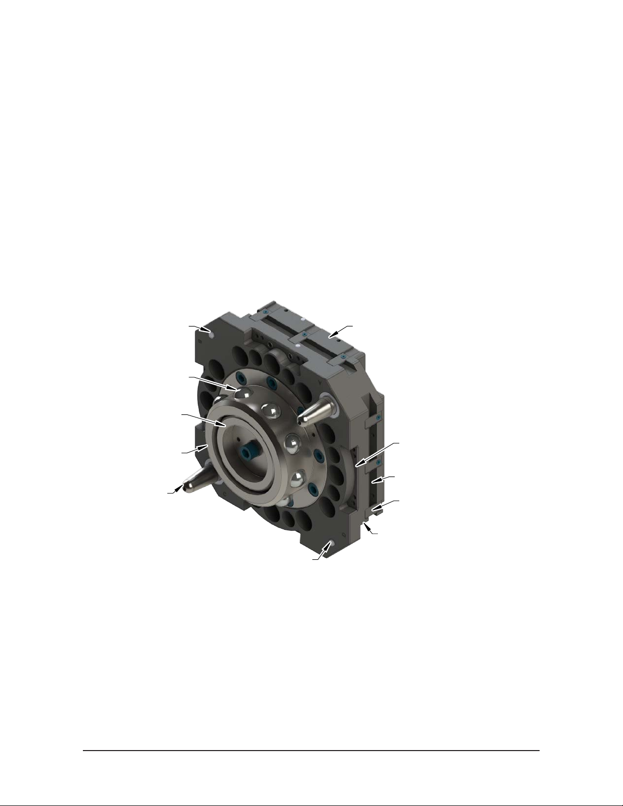
1.1 Master Plate Assembly
The Master plate assembly includes the following features:
• An anodized aluminum body.
• A hardened stainless steel locking mechanism (a cam, male coupling, and chrome steel ball
bearings).
• Hardened steel alignment pins that mate with bushings on the Tool plate.
• (4) ats for mounting optional modules. Flat A is dedicated for mounting an air adapter or a valve
adapter and control/signal module combination. Flats B, C, and D are for optional modules.
• Proximity sensor assemblies used to verify the lock/unlock position of the piston and cam.
• Proximity sensors used to verify Tool plate presence when coupled.
• A mounting pattern for a robot arm or a interface plate.
• Routing channels for the RTL, Lock, and Unlock sensor cables.
Extreme pressure grease is applied to the cam, male coupling, ball bearings, and pins to enhance
performance and maximize the life of the Master plate.
Figure 1.1—Master Plate Assembly
Proximity Sensor
Location (RTL Signal)
Ball Bearing (12)
Cam
Male Coupling
Alignment Pin (2)
Lock/Unlock Air supplied
through Air/Valve Adapter
mounted to Flat A
Common Ledge
Feature for Module
mounted to Flat B, C,
and D
Sensor Cable Channel
Cable Retaining Tab
Internal Proximity Sensor Assembly
(Lock/Unlock) [Not Visible]
Proximity Sensor
Location (RTL Signal)
Pinnacle Park • 1031 Goodworth Drive • Apex, NC 27539 • Tel: 919.772.0115 • Fax: 919.772.8259 • www.ati‑ia.com
B-4
Page 5
Manual,Robotic Tool Changer, QC‑310
Document #9620‑20‑B‑310 Series Base Tool Changer‑27
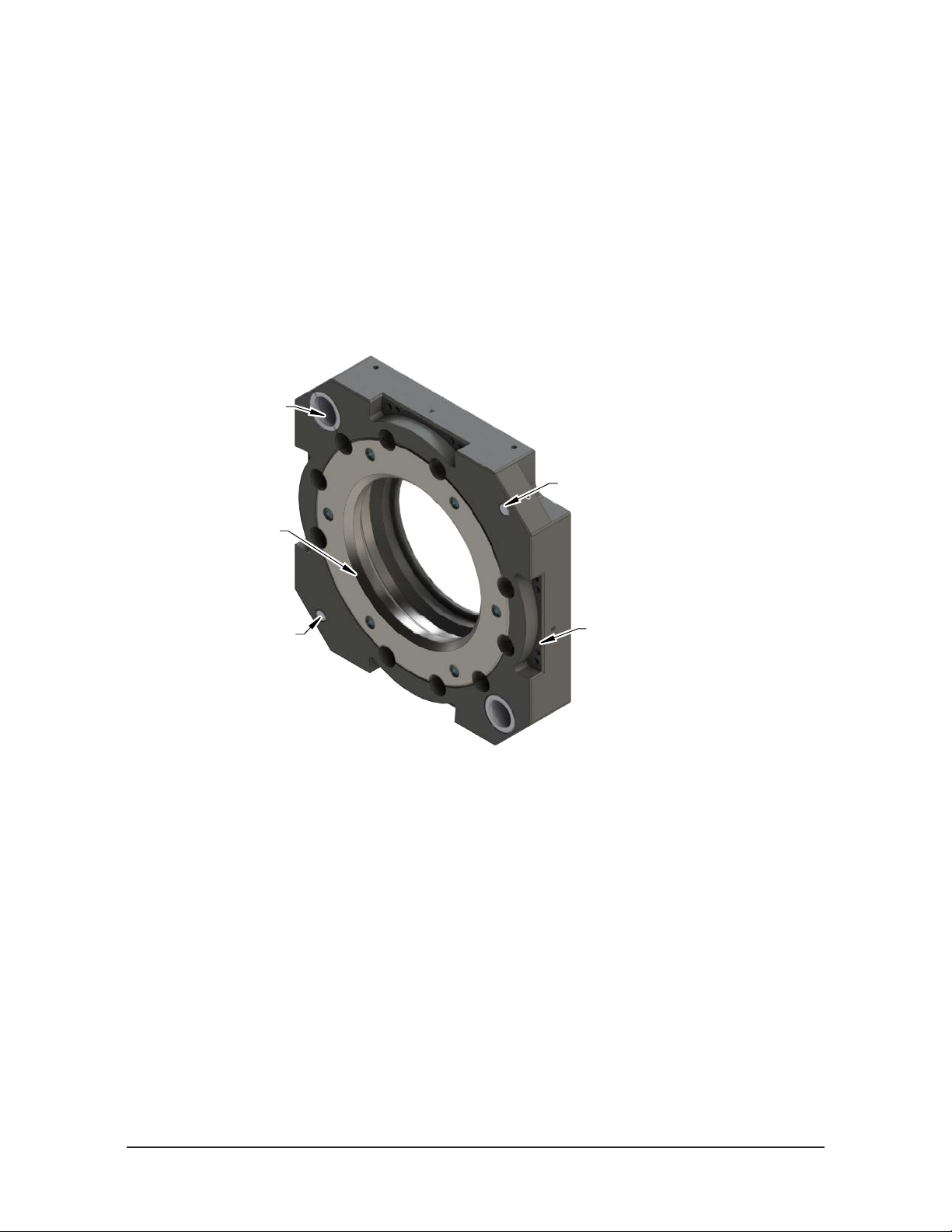
1.2 Tool Plate Assembly
The Tool plate assembly includes the following features:
• An anodized aluminum body.
• A hardened stainless steel bearing race.
• Alignment bushings that mate with pins on the Master plate.
• (4) ats for mounting optional modules. Flat A requires a tool adapter assembly that is compatible
with the air or valve adapter used on the Master Plate. Flats B, C, and D are for optional modules.
• Ferrous metal proximity sensor targets.
• A mounting pattern for customer tooling or a tooling interface plate.
Figure 1.2—T ool Plate Assembly
Alignment Pin Bushing (2)
Alignment Pin Bushing (2)
Proximity Sensor Assembly Target (RTL)
Proximity Sensor Assembly Target (RTL)
Bearing Race
Bearing Race
Proximity Sensor Assembly
Proximity Sensor Assembly
Target (RTL)
Target (RTL)
1.3 Optional Modules
The optional modules are mounted to the Master and Tool plate using a common ledge mounting feature and
pass utilities to customer tooling.
For assistance in choosing the modules for your particular application, visit our website (QC‑310 Series) to
see what is available or contact an ATI sales representative directly.
Common Ledge Feature for
Common Ledge Feature for
Module mounted to Flat A,
Module mounted to Flat A,
B, C, and D
B, C, and D
Pinnacle Park • 1031 Goodworth Drive • Apex, NC 27539 • Tel: 919.772.0115 • Fax: 919.772.8259 • www.ati‑ia.com
B-5
Page 6
Manual,Robotic Tool Changer, QC‑310
Document #9620‑20‑B‑310 Series Base Tool Changer‑27
2. Installation
Mounting the Tool Changer requires the following, refer to Table 2.1:
WARNING: Do not perform maintenance or repair(s) on the Tool Changer or modules unless
the Tool is safely supported or placed in the tool stand, all energized circuits (e.g. electrical,
air, water, etc.) are turned off, pressurized connections are purged and power is discharged
from circuits in accordance with the customer specic safety practices and policies. Injury
or equipment damage can occur with the Tool not placed and energized circuits on. Place
the Tool in the tool stand, turn off and discharge all energized circuits, purge all pressurized
connections, and verify all circuits are de-energized before performing maintenance or
repair(s) on the Tool Changer or modules.
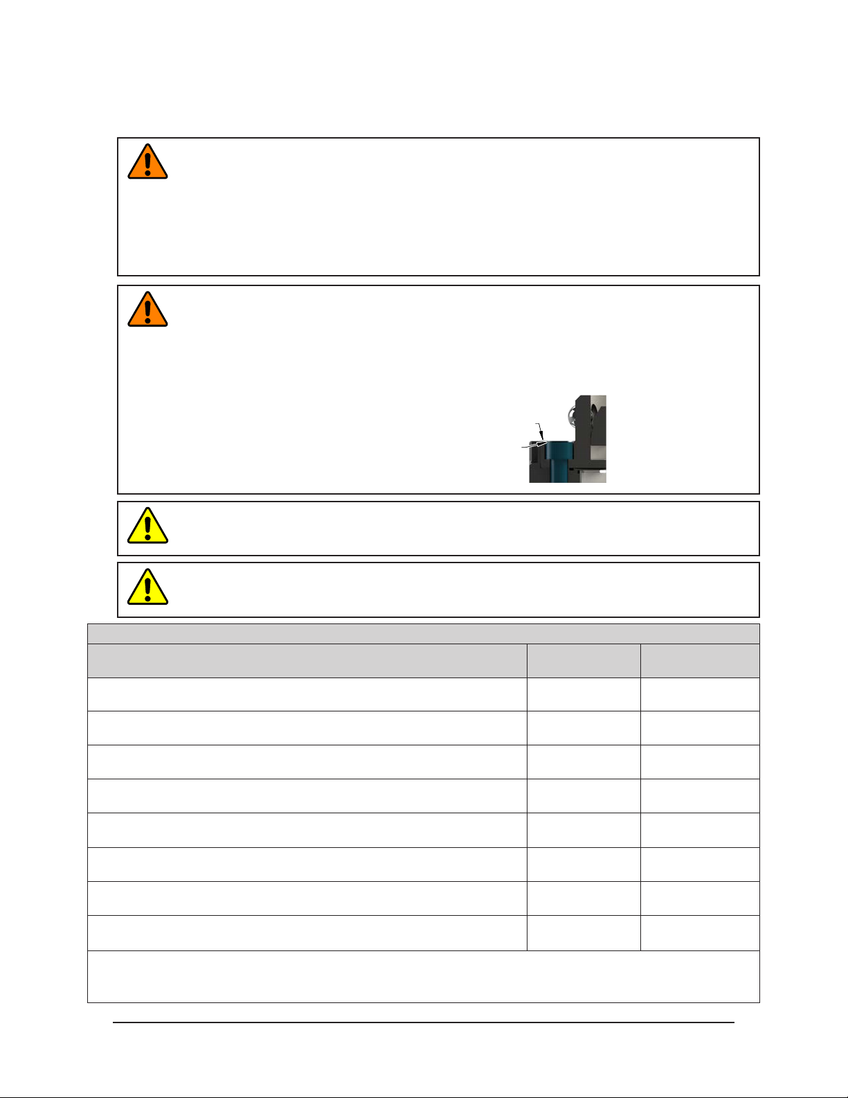
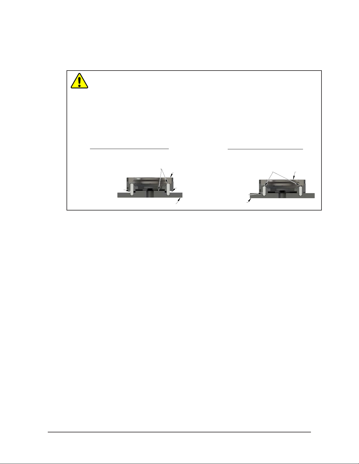
WARNING: Do not use lock washers under the head of the mounting fasteners or allow the
mounting fasteners to protrude above the mating surfaces of the Master and Tool plates.
Allowing fasteners to protrude above the mating surface will create a gap between the Master
and Tool plates and not allow the locking mechanism to fully engage, this can cause damage
to equipment or personal injury. The mounting fasteners must be ush or below the mating
surfaces of the Master and Tool plates.
Head of Mounting Fastener Must Be Flush or
Below Mating Surface. (Do Not Use Lock
Washer under Head of Mounting Fastener.)
Mating Surface
CAUTION: Thread locker applied to fasteners must not be used more than once. Fasteners
might become loose and cause equipment damage. Always apply new thread locker when
reusing fasteners.
CAUTION: Do not use fasteners that exceed the thread depth in the Tool Changer. Refer to
Section 8—Drawings for details on mounting hole thread depth. Secure the Tool Changer with
the proper length fasteners. This is true for both robot and tool interfaces.
Table 2.1—FastenerSize,Class,andTorqueSpecications
Mounting Conditions
Master plate to Interface plate (6061-T6 aluminum)
Minimum thread engagement of 0.71” (18 mm) [1.5X fastener Ø].
Master plate to Interface plate (6061-T6 aluminum)
Minimum thread engagement of 0.94” (24 mm) [1.5X fastener Ø].
Master plate to Robot (steel; USS ≥ 90KSI)
Minimum thread engagement of 0.47” (12 mm) [1.0X fastener Ø].
Master plate to Robot (steel; USS ≥ 90KSI)
Minimum thread engagement of 0.63” (16 mm) [1.0X fastener Ø].
Tool Interface Plate (aluminum) to Tool plate (7075-T6 aluminum)
Minimum thread engagement of 0.59” (15 mm) [1.5X fastener Ø]
Tool plate (6061-T6 aluminum) to Tool Interface Plate (aluminum)
Minimum thread engagement of 0.59” (15 mm) [1.5X fastener Ø].
Tool plate (6061-T6 aluminum) to Tool Interface Plate (aluminum)
Minimum thread engagement of 0.71” (18 mm) [1.5X fastener Ø].
Tool Interface Plate (aluminum) to Tool plate (7075-T6 aluminum)
Minimum thread engagement of 0.94” (24 mm) [1.5X fastener Ø].
Notes:
1. Conrm available engagement with robot manufacturer
2. Removable (blue) Loctite 242® must be used on mounting fasteners.
Fastener Size and
Property Class
M12-1.75
Class 12.9
M16-2.0
Class 12.9
M12-1.75
Class 12.9
M16-2.0
Class 12.9
M10-1.5
Class 12.9
M10-1.5
Class 12.9
M12-1.75
Class 12.9
M16-2.0
Class 12.9
Recommended
Torque
70 ft-lbs
(95 Nm)
165 ft-lbs
(225 Nm)
100 ft-lbs
(135 Nm)
240 ft-lbs
(325 Nm)
38 ft-lbs
(52 Nm)
38 ft-lbs
(52 Nm)
70 ft-lbs
(95 Nm)
165 ft-lbs
(225 Nm)
Pinnacle Park • 1031 Goodworth Drive • Apex, NC 27539 • Tel: 919.772.0115 • Fax: 919.772.8259 • www.ati‑ia.com
B-6
Page 7
Manual,Robotic Tool Changer, QC‑310
A boss and two dowel pins can
Document #9620‑20‑B‑310 Series Base Tool Changer‑27
2.1 Master Interface
The Master plate is typically attached to the robot arm. An interface plate can adapt the Master plate to a
specic robot arm. Alignment features (dowel holes and bosses) accurately position and bolt holes secure
the Master plate to the robot arm or an interface plate. Custom interface plates are available from ATI upon
request (refer to the drawings for technical information on mounting features.)
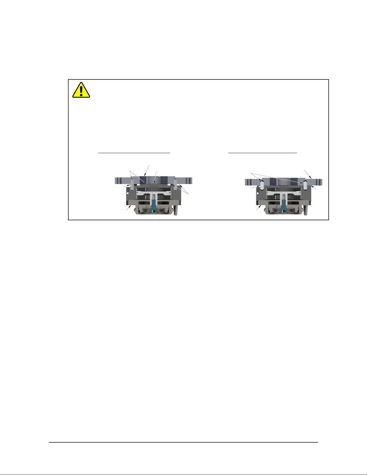
CAUTION: Do not use more than two alignment features when securing a Master plate
to an interface plate. Using more than two alignment features can cause damage to
equipment. Use either two dowel pins or a single dowel pin, along with a boss/recess
feature to align the Master plate with the interface plate.
CAUTION: Do not use dowel pins that are too long or do not allow the interface plate
and Master body to mate ush. Using dowel pins that are too long will cause a gap
between the interface plate and Master body and damage the equipment. Use dowel
pins that will not extend further than allowed by the Master body.
Incorrect Mounting of Master Plate
be difficult to align and can
cause damage to equipment.
Interface Plate
Optional Boss
Correct Mounting of Master Plate
(or a single dowel
used as alignment features.
Two dowel pins
with a boss/recess)
pin along
Interface Plate
Dowel pins that are
too long can cause a
gap between interface
plate and Master Plate.
Master Plate
GapGap
Correct size dowel
pins allow the interface
plate and Master
plate to mount flush.
Master Plate
If the customer chooses to design and build an interface plate, consider the following points:
• The interface plate should include bolt holes for mounting and either two dowel pins or a dowel
pin and a boss for accurate positioning on the robot and Master plate. The dowel and boss features
prevent unwanted rotation. Refer to the robot manual for robot mounting features.
• The thickness of the interface plate must be sufcient to provide the necessary thread engagement
for the mounting bolts.
• Dowel pins must not extend out from the surface of the interface plate farther than the depth of the
dowel holes in the Master plate.
• If a boss is used on the Master plate, a recess of proper depth and diameter must be machined into
the interface plate to correspond with the boss on the Master plate.
• Mounting bolts that are too long can create a gap between the interface plate and the Master plate,
which can damage equipment.
• The interface plate must provide rigid mounting to the Master plate.
• The interface plate design must account for clearances required for Tool Changer module
attachments and accessories.
Flush
Pinnacle Park • 1031 Goodworth Drive • Apex, NC 27539 • Tel: 919.772.0115 • Fax: 919.772.8259 • www.ati‑ia.com
B-7
Page 8
Manual,Robotic Tool Changer, QC‑310
Document #9620‑20‑B‑310 Series Base Tool Changer‑27
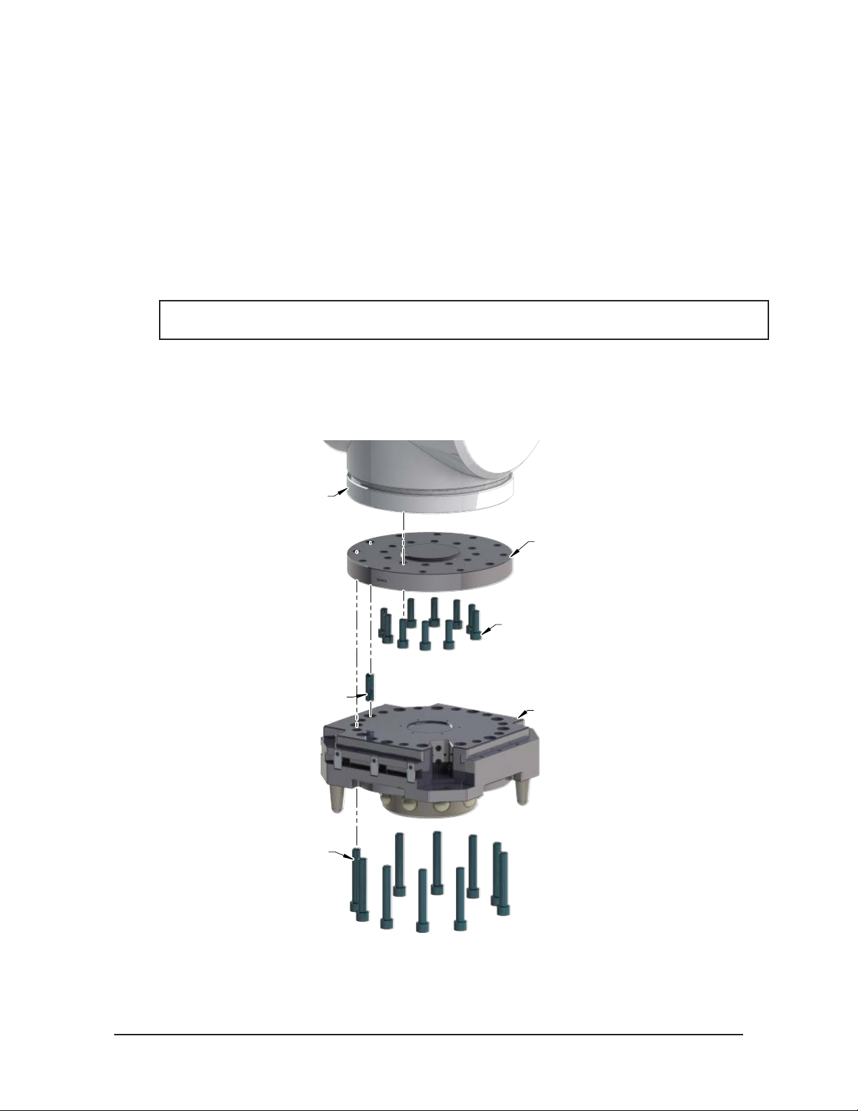
2.2 Master Plate Installation
Tools required: 10 mm or 12 mm hex key, torque wrench
Supplies required: Clean rag, Loctite® 242
1. Clean the mounting surfaces.
2. If required, install the interface plate to the robot arm, align using the boss or dowel pins and secure with
customer supplied fasteners.
3. Align the dowel pins to the corresponding holes in the Master plate and secure the Master plate to the
robot arm or interface plate with customer supplied fasteners.
4. For rst time installation of fasteners with pre‑applied adhesive no additional Loctite is required. If
fasteners are being reused, apply Loctite to threads (see Table 2.1 for fastener specications).
NOTICE: If an ATI interface plate is used, fasteners to mount the Master plate are supplied with
the interface plate.
5. Connect utilities to the appropriate module and Master plate connections. For pneumatic lock and unlock
connection, refer to Section 2.7—Pneumatic Requirements.
6. Safely resume normal operation.
Figure 2.1—Typical Master Plate Installation
Robot Arm
Dowel Pin (Customer Supplied)
Socket Head Cap Screws
(See Table 2.1)
(Customer Supplied)
Robot Interface Plate,
ATI or customer supplied
(If required)
RIP mounting hardware
(Customer supplied)
(If required)
Master Plate
Pinnacle Park • 1031 Goodworth Drive • Apex, NC 27539 • Tel: 919.772.0115 • Fax: 919.772.8259 • www.ati‑ia.com
B-8
Page 9

Manual,Robotic Tool Changer, QC‑310
Document #9620‑20‑B‑310 Series Base Tool Changer‑27
2.3 Master Plate Removal
Refer to Figure 2.1.
Tools required: 10 mm or 12 mm hex key
1. Place the Tool in a secure location.
2. Uncouple the Master and Tool plates.
3. Turn off and de‑energize all energized circuits (e.g. electrical, air, water, etc.).
4. Disconnect all utilities (e.g. electrical, air, water, etc.).
NOTICE: Support the Master plate while removing the fasteners.
5. Remove the socket head cap screws connecting the Master plate to the robot arm or interface plate.
Pinnacle Park • 1031 Goodworth Drive • Apex, NC 27539 • Tel: 919.772.0115 • Fax: 919.772.8259 • www.ati‑ia.com
B-9
Page 10
Manual,Robotic Tool Changer, QC‑310
Correct Mounting of Tool Plate
Interface Plate
Incorrect Mounting of Tool Plate
Document #9620‑20‑B‑310 Series Base Tool Changer‑27
2.4 Tool Interface
The Tool plate is attached to the customer’s tooling. An interface plate can adapt the Tool plate to customer
tooling. Alignment features (dowel holes and a recess) accurately position and bolt holes to secure the Tool
plate to customer tooling. Custom interface plates can be supplied by ATI (refer to the application drawing).
CAUTION: Do not use more than two alignment features when securing a Tool plate
to an interface plate. Using more than two alignment features can cause damage to
equipment. Use either two dowel pins or a single dowel pin, along with a boss/recess
feature to align the Tool plate with the interface plate.
CAUTION: Do not use dowel pins that are too long or do not allow the interface plate
and Tool body to mate ush. Using dowel pins that are too long will cause a gap
between the interface plate and Tool body and damage the equipment. Use dowel pins
that will not extend further than allowed by the Tool body.
Boss and two dowel pins
as alignment features can be
difficult to align and can
damage equipment.
Dowel pins
are too long and
cause a gap between
interface plate and Tool.
Tool Plate
Gap
single dowel pin along with a
proper size allowing
interface plate and Tool
Plate to mount flush.
Two dowel pins (or a
boss/recess) used as
alignment features.
Dowel pins are
Interface Plate
Tool Plate
If the customer chooses to design and build a tool interface plate, consider the following points:
• The interface plate should include bolt holes for mounting and either two dowel pins or a dowel
pin and a boss for accurate positioning on the customer tooling and Tool plate. The dowel and boss
features prevent unwanted rotation.
• Dowel pins must not extend out from the surface of the interface plate farther than the depth of the
dowel holes in the Tool plate.
• The thickness of the interface plate must be sufcient to provide the necessary thread engagement
for the mounting bolts. Fasteners should meet minimum recommended engagement lengths while
not exceeding the maximum available thread depth. Use of bolts that are too long can cause damage
to the tool side changer.
• The plate design must account for clearances required for Tool Changer module attachments and
accessories.
• If a boss is to be used on the interface plate, a boss of proper height and diameter must be machined
into the interface plate to correspond with the recess in the Tool plate.
• The interface plate must have a hole in its center for manually returning the locking mechanism
to the unlocked position under adverse conditions (i.e. unintended loss of power and/or air
pressure). The center access hole with a minimum diameter of 1” (25.4 mm) prevents debris from
contaminating the locking mechanism. Greater protection is provided by leaving the race cover and
grommet in place.
Pinnacle Park • 1031 Goodworth Drive • Apex, NC 27539 • Tel: 919.772.0115 • Fax: 919.772.8259 • www.ati‑ia.com
B-10
Page 11
Manual,Robotic Tool Changer, QC‑310
Document #9620‑20‑B‑310 Series Base Tool Changer‑27
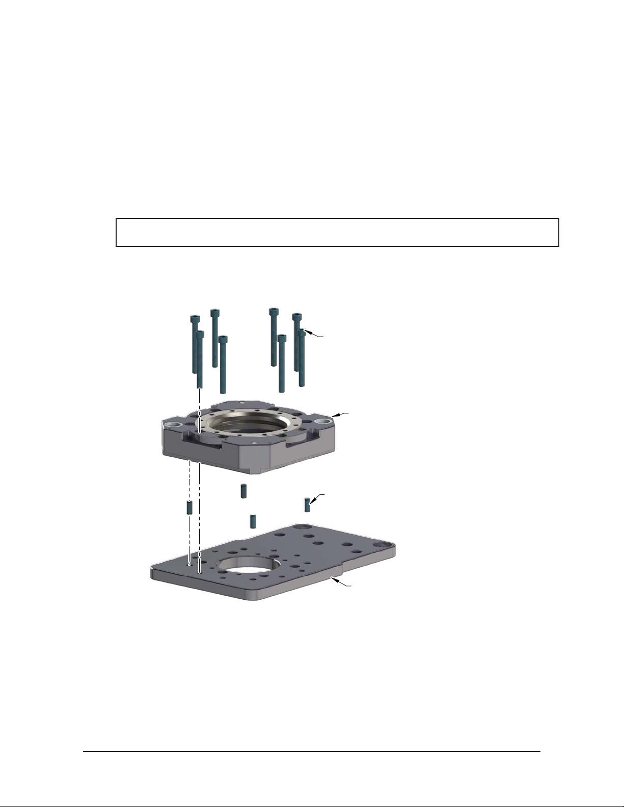
2.5 Tool Plate Installation
Tools required: 8 mm, 10 mm, or 12 mm hex key, toque wrench
Supplies required: Clean rag, Loctite 242
1. Clean the mounting surfaces..
2. If required, install the tool interface plate to the customer tooling, align using the boss or dowel pins and
secure with customer supplied fasteners.
3. Align the dowel pins to the corresponding holes in the Tool plate and secure the Tool plate to the tool
interface plate or customer tooling with customer supplied fasteners.
4. For rst time installation of fasteners with pre‑applied adhesive no additional Loctite is required. If
fasteners are being reused, apply Loctite to threads (see Table 2.1 for fastener specications).
NOTICE: If an ATI interface plate is used, fasteners to mount the Tool plate is supplied with the
interface plate.
5. Connect utilities to the appropriate module and Tool plate connections.
6. Safely resume normal operation.
Figure 2.2—Standard Tool Plate Installation
2.6 Tool Plate Removal
Tools required: 8 mm, 10 mm, or 12 mm hex key
M10-1.5 Socket Head Cap Screws
(See Table 2.1)
(Customer Supplied)
Tool Plate
Dowel Pins (Customer Supplied)
Tool Stand/Tool Interface Plate
(Customer Supplied)
(if required)
1. Place the Tool in a secure location.
2. Uncouple the Master and Tool plates.
3. Turn off and de‑energize all energized circuits (e.g. electrical, air, water, etc.).
4. Disconnect all utilities (e.g. electrical, air, water, etc.).
5. Remove the socket head cap screws connecting the Tool plate to the tooling or tool interface plate.
Pinnacle Park • 1031 Goodworth Drive • Apex, NC 27539 • Tel: 919.772.0115 • Fax: 919.772.8259 • www.ati‑ia.com
B-11
Page 12
Manual,Robotic Tool Changer, QC‑310
)
integrated valve
Document #9620‑20‑B‑310 Series Base Tool Changer‑27
2.7 Pneumatic Requirements
Proper operation of the locking mechanism requires a constant supply of clean, dry, non‑lubricated air, with
the following conditions:
• Pressure range of 60 to 100 psi (4.1 ‑ 6.9 bar) Suggested 80 psi.
• Filtered minimum: 40 microns.
To lock or unlock the Tool Changer, a constant supply of compressed air is required. If there is a loss of air
pressure in the locked state, the cam prole prevents the master plate and tool plate from unlocking, and the
Tool Changer goes into the fail‑safe condition.
CAUTION: Do not use the Tool Changer in a fail-safe condition. Damage to the locking
mechanism can occur. Re-establish air pressure and ensure the Tool Changer is in a
secure lock position before returning to normal operations.
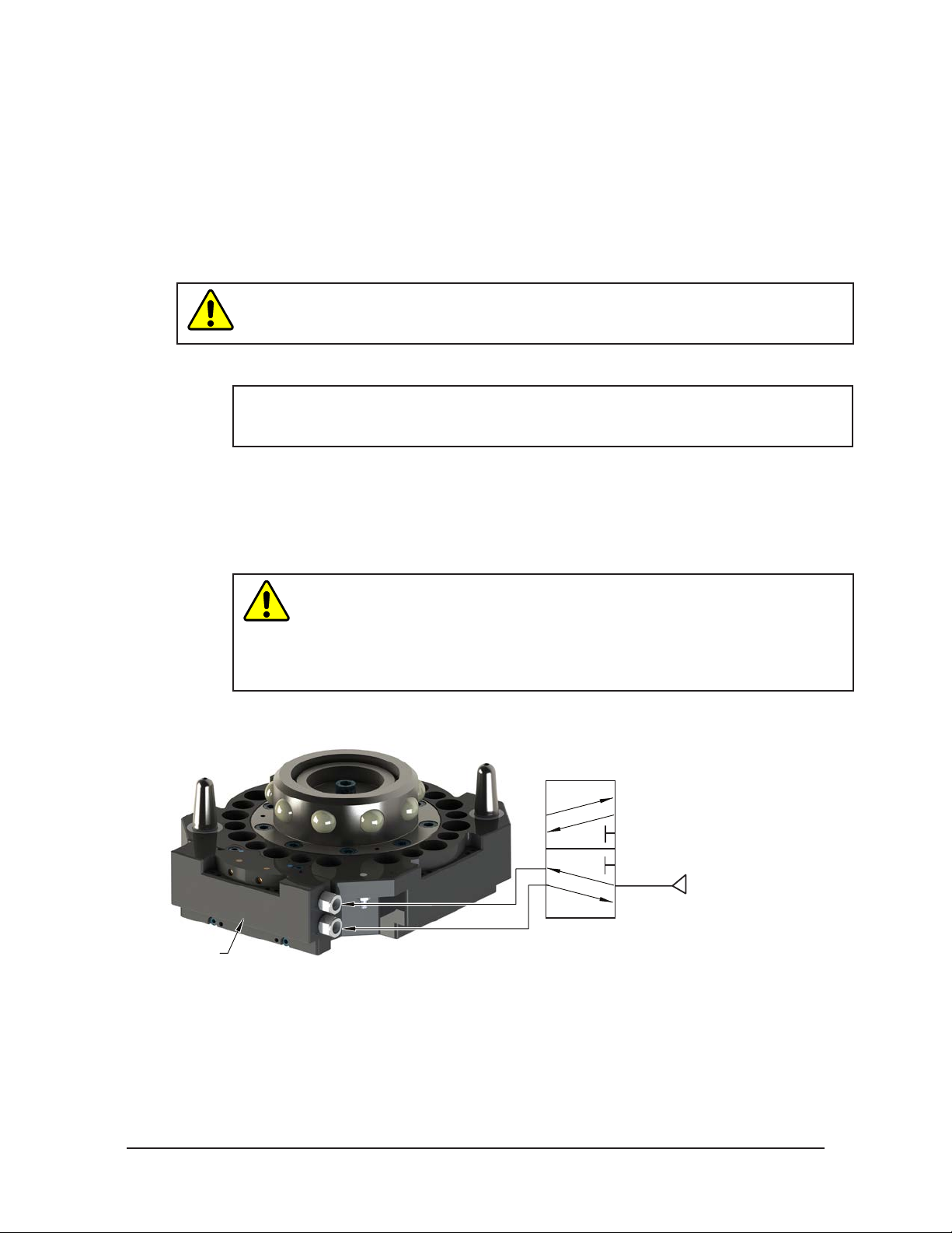
2.7.1 Valve Requirements for Air Adapter Modules
NOTICE: No valve is required when using a valve adapter module. The valve adapter
module has an integrated solenoid valve and only requires the customer to supply a
single air source to the valve adapter.
A customer supplied 2‑position 4‑way or 5‑way valve with either 4‑port or 5‑port conguration
must be used to actuate the locking mechanism in the Master plate. It is imperative that when
air is supplied to the Lock or Unlock Port on the Master plate, that the opposite port be vented
to atmosphere (i.e., when air is supplied to the Lock Port, the Unlock Port must be open to the
atmosphere.) Failure to vent trapped air or vacuum on the inactive port may inhibit operation of the
locking mechanism and prevent coupling or uncoupling.
Air Adapter without
CAUTION: The locking mechanism will not function properly when connected
to a 3-way valve as this type of valve is incapable of venting trapped air or
vacuum from within the Tool Changer. This could result in damage to the
product, attached tooling, or injury to personnel. Connect the Lock and Unlock
supply air to a 2-position 4-way or 5-way valve with either 4-port or 5-port
conguration.
Figure 2.3—Lock and Unlock Pneumatic Connections
4 or 5-way Valve
Supply Clean, Dry,
Non-lubricated Air
Lock Port
Unlock Port
Exhaust
Open to Atmosphere
60 – 100 psi (4.1 – 6.9 Bar
Pinnacle Park • 1031 Goodworth Drive • Apex, NC 27539 • Tel: 919.772.0115 • Fax: 919.772.8259 • www.ati‑ia.com
B-12
Page 13

Manual,Robotic Tool Changer, QC‑310
(3) Blue
Brown (1)
(4) Black
Brown (1)
Black (4)
Blue (3)
+Vs
Output
0 V
NPN
Z
Connector
NPN (Current Sinking)
Document #9620‑20‑B‑310 Series Base Tool Changer‑27
2.8 Electrical Connections
The Tool Changer is available with integrated lock/unlock sensors. If sensors are not used, plugs are
provided to seal the locking mechanism. If a control/signal module is to be utilized on at ‘A’ when ordered,
the sensors will be connected to the module prior to shipping.
2.8.1 PNP Type Lock, Unlock and RTL Sensors (-SM, -SMA, -SL, -SG, -ST
sensor designations)
These sensors are used on 9121‑310xM‑000‑000‑SM, 9121‑310xM‑000‑000‑SMA,
9121‑310xM‑000‑000‑SL, 9121‑310xM‑000‑000‑SG, and 9121‑310xM‑000‑000‑ST.
Table 2.2—PNP (Current Sourcing)
Description Value
Voltage Supply Range
Output Circuit PNP make function (NO)
Figure 2.4—PNP Type Lock, Unlock and RTL Sensors
10-30 VDC
PNP (Current Sourcing)
Brown (1)
Black (4)
PNP
Blue (3)
2.8.2 NPN Type Lock, Unlock and RTL Sensors (-SP, -SE sensor
designations)
These sensors are used on 9121‑310xM‑000‑000‑SP and 9121‑310xM‑000‑000‑SE.
Description Value
Voltage Supply Range
Output Circuit NPN make function (NO)
Figure 2.5—NPN Type Lock, Unlock and RTL Sensors
Z
Connector
+Vs
Output
Brown (1)
0 V
Table 2.3—NPN (Current Sinking)
(4) Black
(3) Blue
10-30 VDC
Pinnacle Park • 1031 Goodworth Drive • Apex, NC 27539 • Tel: 919.772.0115 • Fax: 919.772.8259 • www.ati‑ia.com
B-13
Page 14

Manual,Robotic Tool Changer, QC‑310
Document #9620‑20‑B‑310 Series Base Tool Changer‑27
2.8.3 Namur Type Lock and Unlock Sensors (-SV sensor designation)
This section applies to the following part number designator: (‑SV).
Example: 9120‑310xM‑000‑000‑SV
Table 2.4—PNP (Current Sourcing)
Description
Voltage Supply Range 5-30 VDC
Operating Current Remote
Non-Actuated Current Consumption ≥ 2.1 mA
Actuated Current Consumption ≤ 1.2 mA
Nominal Sensing Distance Sn 1.0 mm
Output Circuit 2-Wire DC NAMUR
Figure 2.6—NAMUR Type Lock and Unlock Sensors
Lock and Unlock Sensors
Value
NAMUR
Output: Y1
Connector
(4) Black
+
1
-
Remote
Amplifier
Brown (1)
(3) Blue
4
3
Pinnacle Park • 1031 Goodworth Drive • Apex, NC 27539 • Tel: 919.772.0115 • Fax: 919.772.8259 • www.ati‑ia.com
B-14
Page 15

Manual,Robotic Tool Changer, QC‑310
Document #9620‑20‑B‑310 Series Base Tool Changer‑27
3. Operation
The Master plate locking mechanism is pneumatically driven to couple and uncouple with the Tool plate bearing
race.
CAUTION: Operation of the Tool Changer is dependent on maintaining an air pressure of 60
to 100 psi (4.1 - 6.9 bar). Damage to the locking mechanism could occur. Robot motion must
be halted if the air supply pressure drops below 60 psi (4.1 bar).
NOTICE: All Tool Changers are lubricated prior to shipment. The customer must apply additional
lubricant to the locking mechanism components and alignment pins prior to operation. Tubes of
lubricant for this purpose are shipped with every Tool Changer. Standard Tool Changers require
MobilGrease XHP222 Special (a NLGI #2 lithium complex grease with molybdenum disulde). For
custom applications, such as food grade or surgical applications, specialized lubricants might be
required.
Coupling should occur with the Master plate in the No‑Touch™ locking zone. As coupling occurs, the Master plate
should pull the Tool plate into the locked position.
Program the robot to minimize misalignment during coupling and uncoupling. Greater offsets can be
accommodated by the Master and Tool plates but will increase wear. Misalignments can be caused by improper tool
stand design. Refer to Tool Storage Considerations section.
Figure 3.1—OffsetDenitions
Master Plate
Tool Plate
Z
Y
Twisting
X
Table 3.1—Maximum Recommended Offsets Prior to Coupling
No-Touch Zone Z
Model
QC-310
Notes:
1. Maximum values shown. Decreasing values minimizes wear.
2. Allowable values may be greater, but greater offsets increase wear.
Offset
1
(Max)
0.10”
(2.5 mm)
X and Y Offset
2
(Max)
±0.08”
(2 mm)
X, Y, and Z Offset
Cocking Offset
(Max)
±0.7° ±1°
Cocking
Offset
(About X
and Y)
Twisting Offset
(Max)
Pinnacle Park • 1031 Goodworth Drive • Apex, NC 27539 • Tel: 919.772.0115 • Fax: 919.772.8259 • www.ati‑ia.com
B-15
Page 16

Manual,Robotic Tool Changer, QC‑310
Document #9620‑20‑B‑310 Series Base Tool Changer‑27
3.1 Conditions for Coupling
The following conditions should be considered when operating the Tool Changer. For more details about
programming the robot, refer to the Operation section of the Control/Signal Module Manual.
CAUTION: Do not attempt to couple the Tool Changer when in locked position. The
locking mechanism must be in the unlock position when attempting to couple the Tool
Changer. Failure to adhere to this condition may result in damage to the unit and/or the
robot. Always unlock the Master prior to coupling to a Tool.
1. Unlock the Tool Changer by removing air pressure from the lock port and supplying air pressure to the
unlock port (if equipped, the unlock sensor indicates the Tool Changer is unlocked).
NOTICE: For Tool Changers with a control/signal module and air/valve adapters with a double
solenoid valve, turn the Unlatch output ON and turn the Latch output OFF. For Tool Changers
with a control/signal module and air/valve adapters with a single solenoid valve, turn the Unlatch
output ON. Some control/signal modules prevent the Tool Changer from being unlocked unless
the Master and Tool are coupled and nested properly in the tool stand, a manual override
procedure is required to unlock the Tool Changer. Refer to your Control/Signal Module Manual
for instructions.
2. Position the Master above the Tool and move the Master into ready to lock position. The mating surfaces
of the Master and Tool should be parallel and not touching. Make sure that the tapered alignment
pins from the Master enter the alignment holes on the Tool. The alignment pins should be relatively
concentric with the alignment bushings with no contact between the two.
3. It is recommended that the mating faces of the Master and Tool not be touching but be within the
No‑Touch distance of each other when coupling to minimize stress and wear on the locking mechanism.
The locking mechanism allows the Master to “pull up” the Tool with gaps between the two sides.
CAUTION: Direct contact of the Master and Tool mating surfaces is not suggested
or required just prior to coupling. Contact may result in damage to the unit and/or the
robot. No-Touch locking technology allows the unit to couple with a separation distance
between the Master and Tool.
4. The RTL (Ready‑To‑Lock) sensor and target that are built into the Tool Changer must be positioned
within approximately 0.05” (1.5 mm) of each other for the sensors to detect Tool presence. RTL signals
are not required to couple the Tool Changer but are recommended as a conrmation of coupling prior to
removing the Tool from the tool stand.
NOTICE: At this point, communication is initiated with the ATI Tool and downstream nodes. If
equipped, Tool-ID and communications become available. Depending on the type of control/
signal module, additional notications such as RTLV, TSRV, TSIV, Tool Present, Unlatch
Enabled, and other notications can provide verication of properly functioning system
components.
5. Couple the Tool Changer by releasing the air pressure from the unlock port and supplying air pressure
to the lock port. Air must be maintained on the lock port during operation to assure rigid coupling (if
equipped, the lock sensor indicates the Tool Changer is in the locked position).
NOTICE: For Tool Changers with a control/signal module and air/valve adapters with a double
solenoid valve, turn the Unlatch output OFF and turn the Latch output ON. For Tool Changers
with a control/signal module and air/valve adapters with a single solenoid valve, turn the Unlatch
output OFF.
Pinnacle Park • 1031 Goodworth Drive • Apex, NC 27539 • Tel: 919.772.0115 • Fax: 919.772.8259 • www.ati‑ia.com
B-16
Page 17

Manual,Robotic Tool Changer, QC‑310
Document #9620‑20‑B‑310 Series Base Tool Changer‑27
6. A sufcient delay must be programmed between locking valve actuation and robot motion so that the
locking process is complete before moving the robot. If equipped with Lock and Unlock sensors, the
Lock signal should read “ON” (true) and the Unlock signal should read “OFF” (false).
NOTICE: If the locking mechanism has been actuated and both the Lock and Unlock signals are
OFF, then a “missed tool” condition has occurred (for example, the Tool is not in the stand or is
not positioned properly). In this case an error should be generated and the robot program
halted. The situation requires manual inspection to determine the cause of the problem. Some
congurations will require a manual unlock of the Master plate before attempting coupling, refer
to the Control/Signal Module Manual for instructions.
NOTICE: The locking mechanism must be in the unlock state before another attempt is made to
couple or damage could occur to the robot and/or the Tool Changer.
3.2 Fail-Safe Operation
A fail‑safe condition occurs when there is an unintended loss of lock air pressure to the Master plate. When
air pressure is lost, the Tool Changer relaxes and there may be a slight separation between the Master and
Tool plates. The lock sensor may indicate that the unit is not locked. ATI’s patented fail‑safe feature utilizes
a multi‑tapered cam to trap the ball bearings and prevent an unintended release of the Tool plate. Positional
accuracy of the tooling is not maintained during this fail‑safe condition. Do not operate the Tool Changer
in the fail‑safe condition. If source air is lost to the unit, movement should be halted until air pressure is
restored.
After air pressure is re‑established to the Master plate, the locking mechanism will energize and securely
lock the Master and Tool plates together. In some cases when the load on the tool changer is signicantly
off center, it may be necessary to position the load underneath the tool changer or return the tool to the tool
storage location to ensure a secure lock condition. If equipped, make sure the lock sensor indicates the Tool
Changer is in the locked position before resuming normal operations. Consult your Control/Signal Module
Manual for specic error recovery information.
CAUTION: Do not use the Tool Changer in a fail-safe condition. Damage to the locking
mechanism could occur. Re-establish air pressure and ensure the Tool Changer is in a
secure lock position before returning to normal operations.
Pinnacle Park • 1031 Goodworth Drive • Apex, NC 27539 • Tel: 919.772.0115 • Fax: 919.772.8259 • www.ati‑ia.com
B-17
Page 18

Manual,Robotic Tool Changer, QC‑310
Document #9620‑20‑B‑310 Series Base Tool Changer‑27
3.3 Conditions for Uncoupling
Refer to your Air/Valve Adapter and/or Control/Signal Module Manual’s Operation section for operation
during coupling/uncoupling.
1. Move the robot to position the Tool plate in the tool stand. The position for coupling and uncoupling are
the same.
NOTICE: Depending on the type of control/signal module, additional notications such as TSRV,
TSIV, and other notications can provide verication of properly functioning system components.
2. Unlock the Tool Changer by releasing the air pressure from the lock port and supplying air pressure to
the unlock port. The Tool Changer locking mechanism moves to the unlocked position and the Tool plate
releases from the Master plate (If equipped, the unlock sensor indicates the Tool Changer is unlocked).
NOTICE: For Tool Changers with a control/signal module and air/valve adapters with a double
solenoid valve, turn the Unlatch output ON and turn the Latch output OFF. For Tool Changers
with a control/signal module and air/valve adapters with a single solenoid valve, turn the Unlatch
output ON.
CAUTION: This Tool Changer may be equipped with a tool stand Interlock (TSI) feature
that physically breaks the Unlatch solenoid circuit. Proper use of the TSI prevents
unwanted Unlock software commands from being recognized until the circuit is made.
Make sure the Tool Changer is positioned properly to trip actuate the TSI switch when
the Tool is in the tool stand.
3. A sufcient delay must be programmed between unlocking valve actuation and robot motion so that
the unlocking process is complete before moving the robot. If equipped with lock and unlock sensors,
the Unlock signal should read “on” (true) and the Lock signal should read “off” (false). Any other
condition indicates a problem and the robot program should be halted. Once the Lock and Unlock
signals in the proper state, the Master plate may be moved away from the Tool plate in the axial
direction.
The robot and Master plate can now proceed to another Tool plate for coupling and subsequent operations.
3.4 ToolIdentication
When using multiple Tools, it is good practice to implement a Tool‑ID system that identies each Tool
with a unique code. Tool‑ID can be used to verify that the robot has picked up the proper Tool. Modules
with Tool‑ID are available for purchase through the ATI website. Go to http://www.ati‑ia.com/products/
toolchanger/tool_changer_modules.aspx for products available or contact ATI for assistance.
Pinnacle Park • 1031 Goodworth Drive • Apex, NC 27539 • Tel: 919.772.0115 • Fax: 919.772.8259 • www.ati‑ia.com
B-18
Page 19

Manual,Robotic Tool Changer, QC‑310
Document #9620‑20‑B‑310 Series Base Tool Changer‑27
3.5 Tool Storage Considerations
NOTICE: Tool stand design is critical to the operation of the Tool Changer. Improperly designed
tool stands can cause jamming and excessive wear of the Tool Changer components.
Tool plates with customer tooling attached may be stored in a tool stand. ATI provides compatible tool
stands designed for durability, longevity, and maximum adaptability to t most customers’ applications. The
ATI TSL (Tool Stand Large) system is compatible with ATI Tool Changer sizes QC‑150 and larger. The TSL
systems can be equipped with horizontal modules, clamp modules, and different types of tool sensing. Visit
the ATI Web Site http://www.ati‑ia.com/products/toolchanger/toolstand/large/LargeStand.aspx for products
available or contact ATI for assistance.
If the customer is supplying the tool stand, it must provide a xed, repeatable, level, and stable position
for tool pick‑up and drop‑off. The tool stand must support the weight of the Tool Changer Tool plate, tool
interface plate, optional modules, cables, hoses, and customer tooling without allowing deection in excess
of the offsets specied.
Ideally, the Tool should be hanging vertically in the tool stand so that gravity assists to uncouple the Tool
plate from the Master plate during unlocking. It is possible to design tool stands that hold tools in the
horizontal position, but the necessary compliance must be provided during coupling and uncoupling. In
general, “horizontal‑position” tool stands cause more wear on the locking mechanism and locating features
of the Tool Changer and tool stand.
A variety of methods may be used to position the Tool in the tool stand. A common method is to use tapered
alignment pins and bushings. Robot programming and positional repeatability are vital in Tool pick‑up and
drop‑off.
A sensor that detects the presence of the Tool in the tool stand is recommended. The sensor may be used
prior to coupling to ensure the Tool is seated in the stand. Sensors may also be used as the robot starts to
move away after uncoupling. Sensors provide a safety measure if a Tool becomes jammed in the stand or if
the Tool fails to release from the robot.
Proximity sensors should be positioned so that the sensing face is vertical to prevent metal shavings, weld
spatter, or other debris from falling on the sensor and creating false readings.
Tool stands debris shields can cover Tools and modules to protect them in dirty environments, such as
grinding or welding. Alternatively, positioning tool stands in areas shielded from weld spatter, uids,
adhesives, or other debris would eliminate the need for debris shields.
Pinnacle Park • 1031 Goodworth Drive • Apex, NC 27539 • Tel: 919.772.0115 • Fax: 919.772.8259 • www.ati‑ia.com
B-19
Page 20

Manual,Robotic Tool Changer, QC‑310
Document #9620‑20‑B‑310 Series Base Tool Changer‑27
4. Maintenance
WARNING: Do not perform maintenance or repair(s) on the Tool Changer or modules unless
the Tool is safely supported or placed in the tool stand, all energized circuits (e.g. electrical,
air, water, etc.) are turned off, pressurized connections are purged and power is discharged
from circuits in accordance with the customer specic safety practices and policies. Injury
or equipment damage can occur with the Tool not placed and energized circuits on. Place
the Tool in the tool stand, turn off and discharge all energized circuits, purge all pressurized
connections, and verify all circuits are de-energized before performing maintenance or
repair(s) on the Tool Changer or modules.
NOTICE: The cleanliness of the work environment strongly inuences the trouble free operation of
the Tool Changer. The dirtier the environment, the greater the need for protection against debris.
Protection of the entire EOAT, the Master, the Tool and all of the modules may be necessary. Protective
measures include the following:
Placement of the tool stands away from the debris generators.
• Covers incorporated into the tool stands.
• Guards, deectors, air curtains, and similar devices built into the EOAT and the tool stand.
4.1 Preventive Maintenance
A visual inspection and preventive maintenance schedule is provided in the following table. Detailed assembly drawings
are provided in Section 8—Drawings of this manual. Refer to module sections for detailed preventive maintenance steps
for all utility modules.
Table 4.1—Maintenance
Application(s) Tool Change Frequency Inspection Schedule
General Usage Material Handling Docking Station
Welding/Servo/Deburring, Foundry Operations (Dirty Environments) All Weekly
Checklist
Mounting Fasteners
г Inspect fasteners for proper torque, interferences, and wear. Tighten and correct as required. Refer to Table 2.1
Ball Bearings/Alignment Pins/Bushings/Bearing Race
г Inspect for wear and proper lubrication. MobilGrease XHP222 Special a NLGI #2 lithium complex grease with
molybdenum disulde additive is suggested for locking mechanism and alignment pin lubrication. Over time,
lubricants can become contaminated with debris. Therefore, it is recommended to thoroughly clean the existing
grease and replace with new as needed. See Section 4.2—Cleaning and Lubrication of the Locking Mechanism and
Alignment Pins.
г Inspect for excessive alignment pin/bushing wear, may be an indication of poor robot position during pickup/drop-off.
Adjust robot position as needed. Check tool stand for wear and alignment problems. To replace worn alignment pins,
refer to Section 5.2.3—Alignment Pin Replacement.
г Inspect for wear on the ball bearings/bearing race, may be an indication of excessive loading.
Sensors and Cables
г Inspect sensor cable connectors for tightness, if loose tighten connections.
г Inspect sensor cables for any damage, cuts, and abrasion. Replace as necessary. Refer to Section 5.2.1.1—Individual
Lock and Unlock Sensor Assemblies Replacement and Section 5.2.1.2—RTL Sensor Cable Replacement Procedure.
Hoses
г Inspect hose connection for tightness and leaks. If leaking or loose secure hose connection.
г Inspect hoses for interferences, abrasions, cuts, and leaks. Replace as required.
Electrical Contacts/Pin Block (Modules)
г Inspect for damage, debris, and stuck/burnt pins. Clean pin blocks as required, refer to Section 4.3—Pin Block
Inspection and Cleaning.
Seals (Modules)
г Inspect for wear, abrasion, and cuts. Refer to Section 5.2.2—V‑ring Seal Replacement
> 1 per minute Weekly
< 1 per minute Monthly
Pinnacle Park • 1031 Goodworth Drive • Apex, NC 27539 • Tel: 919.772.0115 • Fax: 919.772.8259 • www.ati‑ia.com
B-20
Page 21

Manual,Robotic Tool Changer, QC‑310
Document #9620‑20‑B‑310 Series Base Tool Changer‑27
4.2 Cleaning and Lubrication of the Locking Mechanism and Alignment Pins
Supplies required: Clean rag, MobilGrease XHP222 Special Grease
1. Place the Tool in a secure location.
2. Uncouple the Master and Tool plates.
3. Turn off and de‑energize all energized circuits (e.g. electrical, air, water, etc.).
4. Use a clean rag to thoroughly remove any lubricant and debris from the ball bearings, male coupling,
cam, and alignment pins.
Figure 4.1—Cleaning Ball Bearings and Outer Surfaces of Male Coupling
5. Use a clean rag to thoroughly remove any lubricant and debris from the inner surface of the male
coupling and cam.
Figure 4.2—Cleaning Ball Bearings, Cam and Inner Surfaces of Male Coupling
Pinnacle Park • 1031 Goodworth Drive • Apex, NC 27539 • Tel: 919.772.0115 • Fax: 919.772.8259 • www.ati‑ia.com
B-21
Page 22

Manual,Robotic Tool Changer, QC‑310
Clean Bushing Surfaces
.
Document #9620‑20‑B‑310 Series Base Tool Changer‑27
6. Check each ball bearing to make sure it moves freely in the male coupling. Additional cleaning may be
necessary to free up any ball bearings that are sticking in place.
Figure 4.3—Check Ball Bearing Movement
7. Apply a liberal coating of lubricant to the ball bearings, the male coupling (inside and out), and the
alignment pins.
Figure 4.4—Apply Lubricant to Locking Mechanism
Apply Lubricant on Alignment Pins
and Outer Surface of Male Coupling
8. Use a clean rag to thoroughly remove any lubricant and debris from the Tool plate bearing race and
bushings.
NOTICE: No application of lubrication is necessary on the Tool plate components.
9. Safely resume normal operation.
Figure 4.5—Clean Tool Plate Surfaces of Locking Mechanism
Apply Lubricant on Inner
Surface of Male Coupling
Clean Bearing Race
Surfaces
Pinnacle Park • 1031 Goodworth Drive • Apex, NC 27539 • Tel: 919.772.0115 • Fax: 919.772.8259 • www.ati‑ia.com
B-22
Page 23

Manual,Robotic Tool Changer, QC‑310
Tool Module Pin Block
Master Module Pin Block
Note: Pin blocks shown are for
illustration purposes only.
Weld Debris
Blackened Pins
Stuck Pins
Pin Block Damage
Document #9620‑20‑B‑310 Series Base Tool Changer‑27
4.3 Pin Block Inspection and Cleaning
Tools required: Nylon Brush (ATI Part Number 3690‑0000064‑60)
1. Place the Tool in a secure location.
2. Uncouple the Master and Tool plates.
3. Turn off and de‑energize all energized circuits (e.g. electrical, air, water, etc.).
4. Inspect the Master and Tool pin blocks for debris or darkened pins.
Figure 4.6—Inspect Master and Tool Pin Blocks
5. If debris or darkened pins are present, use a vacuum to remove the debris, and clean using a nylon brush
(ATI Part Number 3690‑0000064‑60).
NOTICE: Do not use an abrasive media, cleaners, or solvents to clean the contact pins. Using
abrasive media, cleaners, or solvents will cause damage to the contact surface, or cause pins to
stick. Clean contact surfaces with a vacuum or non-abrasive media such as a nylon brush (ATI
Part Number 3690-0000064-60)
Figure 4.7—Clean Pin Blocks with a Nylon Brush
6. Inspect the Master and Tool pin blocks for stuck pins or pin block damage.
Figure 4.8—Stuck Pin and Pin Block Damage
Note: Pin blocks shown are for
illustration purposes only.
7. If there are stuck pins or pin block damage, contact ATI for either a possible pin replacement procedure
or module replacement.
8. Safely resume normal operation.
Pinnacle Park • 1031 Goodworth Drive • Apex, NC 27539 • Tel: 919.772.0115 • Fax: 919.772.8259 • www.ati‑ia.com
B-23
Page 24

Manual,Robotic Tool Changer, QC‑310
Document #9620‑20‑B‑310 Series Base Tool Changer‑27
5. Troubleshooting and Service Procedures
The following section provides troubleshooting and service information to help diagnose conditions and repair the
Tool Changer or control/signal module.
WARNING: Do not perform maintenance or repair(s) on the Tool Changer or modules unless
the Tool is safely supported or placed in the tool stand, all energized circuits (e.g. electrical,
air, water, etc.) are turned off, pressurized connections are purged and power is discharged
from circuits in accordance with the customer specic safety practices and policies. Injury
or equipment damage can occur with the Tool not placed and energized circuits on. Place
the Tool in the tool stand, turn off and discharge all energized circuits, purge all pressurized
connections, and verify all circuits are de-energized before performing maintenance or
repair(s) on the Tool Changer or modules.
5.1 Troubleshooting Procedures
Check these conditions for all symptoms prior to troubleshooting:
• Proper pneumatic and electrical connections have been made to the Quick Change.
• Air is supplied at a minimum of 60 psi (4.1 Bar).
• No air or vacuum can be trapped in a de‑energized Lock or Unlock Port (pressure must be vented to
atmosphere).
Table 5.1—QC-76 Troubleshooting
Symptom Cause Resolution
Debris caught between the Master
and Tool plates.
Insufcient or no air pressure supply
to the Lock or Unlock ports.
Air pressure trapped in de-energized
Tool Changer will not
lock and/or unlock (or
Lock sensor does not
indicate Tool Changer
is Locked)
Unit is locked but Lock
signal does not read
“on” (true).
Unit is unlocked but
Unlock signal does not
read “on” (true).
Units Equipped with Electrical/Servo/Control/Signal Modules
Lock or Unlock ports.
Pneumatic connections loose or
damaged.
The ball bearings and/or cam are not
moving freely in the male coupling.
The Master and Tool plates are not
within the specied No‑Touch sone
when attempting to lock.
Lock sensor/cable is damaged.
Unlock sensor/cable is damaged.
Clean debris from between the Master and Tool
plates. Verify mounting fasteners are secure and does
not protrude above the mating surfaces.
Veried proper air pressure and pneumatic valve
is supplied. Refer to
Requirements.
Air pressure must be vented to the atmosphere
properly, refer to Section 2.7—Pneumatic
Requirements.
Inspect hose connection for tightness and leaks. If
leaking or loose secure hose connection. Inspect
hoses for interferences, abrasions, cuts, and leaks.
Replace as required.
Clean and lubricate as needed to restore smooth
operation (see
of the Locking Mechanism and Alignment Pins.
Check that the Tool is properly seated in the tool
stand. Refer to
the robot to bring the Master and Tool plate closer
together prior to attempting to lock.
Replace the lock sensor sub-assembly as
necessary. Refer to Section Table 3.1——Maximum
Recommended Offsets Prior to Coupling and
Section 5.2.2—V‑ring Seal Replacement.
Replace the unlock sensor sub-assembly as
necessary. Refer to Section Table 3.1——Maximum
Recommended Offsets Prior to Coupling and
Section 5.2.2—V‑ring Seal Replacement.
Section 2.7—Pneumatic
Section 4.2—Cleaning and Lubrication
Section 8—Drawings. Re-teach
Pinnacle Park • 1031 Goodworth Drive • Apex, NC 27539 • Tel: 919.772.0115 • Fax: 919.772.8259 • www.ati‑ia.com
B-24
Page 25

Manual,Robotic Tool Changer, QC‑310
Document #9620‑20‑B‑310 Series Base Tool Changer‑27
Table 5.1—QC-76 Troubleshooting
Symptom Cause Resolution
Inspect V-ring seal for damage, and if
necessary, replace the damaged seal. Refer to
Section 5.2.2—V‑ring Seal Replacement.
Check that the cable connections are secure, and
cables are not damaged.
Loss of
Communication
Debris in and around contact pins.
Contact pin worn or damaged.
Cable connections loose or cables
damaged.
5.2 Service Procedures
Component replacement procedures are provided in the following section.
5.2.1 Sensor Replacement Procedures
Figure 5.1—Determine what type of Lock/Unlock sensors the Tool Changer uses:
Lock and Unlock Sensor Assemblies
Replacement (Current Revision)
(Sensor Designations: -SM, -ST, -SP, -SMA, -S0)
Refer to Section 5.2.1.1—Individual Lock and
Unlock Sensor Assemblies Replacement
Lock and Unlock Sensors in body
Contact ATI for replacement procedure and
serviceable part information.
Lock and Unlock Sensor Assembly
Replacement
Contact ATI for replacement procedure and
serviceable part information.
Unlock sensor in body and Lock sensor
assembly
Contact ATI for replacement procedure and
serviceable part information.
Pinnacle Park • 1031 Goodworth Drive • Apex, NC 27539 • Tel: 919.772.0115 • Fax: 919.772.8259 • www.ati‑ia.com
B-25
Page 26

Manual,Robotic Tool Changer, QC‑310
Document #9620‑20‑B‑310 Series Base Tool Changer‑27
5.2.1.1 Individual Lock and Unlock Sensor Assemblies Replacement
Parts required: Refer to Section 6—Serviceable Parts
Tools required: 2 mm, 2.5 mm, and 5 mm hex key, torque wrench
1. Place the Tool in a secure location.
2. Uncouple the Master and Tool plates.
3. Turn off and de‑energize all energized circuits (e.g. electrical, air, water, etc.).
4. If there is an optional module on Flat D, remove the (2) M6 socket head cap screws
securing the module(s) to the Tool Changer body using a 5 mm hex key and lift it
off from Flat D. Refer to Figure 5.2.
5. Remove the (3) M3 socket at head cap screws and three cable retaining tabs on
Flat D of the Tool Changer body using a 2 mm hex key.
6. Unscrew the Lock and/or Unlock sensor cable connector from the air/valve adapter
or control/signal module.
7. Remove the (2) M3 socket head cap screws that secure the Lock and/or Unlock
sensor assembly to the Tool Changer body using a 2.5 mm hex key. Pull the sensor
assembly straight out from the Tool Changer body.
8. Remove the Lock and/or Unlock sensor assembly from the cable channel of the
Tool Changer body. There is an O‑ring around the sensor between the assembly and
the Tool Changer body, ensure O‑ring came off with old sensor before continuing.
Discard the removed sensor assembly.
Figure 5.2—Lock and Unlock Sensor Assembly Replacement
Lock Sensor Assembly
Unlock Sensor Assembly
M3 Socket Head Cap Screws
9. Route the new Lock and/or Unlock sensor cable into the cable channel of the Tool
10. Attach the Lock and/or Unlock sensor cable connectors to the proper connector on
11. Insert the Lock and/or Unlock sensor assembly into the Tool Changer body as
CAUTION: The Lock and Unlock sensor assemblies are precision
aligned and permanently assembled at the factory. Do not attempt
to disassemble and rebuild.
Valve Adapter and
Control Module on Flat A
Connects to "L"
Connects to "U"
M6 Socket Head
Cap Screws
(3) Cable
Retaining Tabs
M3 Socket Flat
Head Screws
Remove Module on Flat D
Changer body.
the control/signal module.
shown in Figure 5.2. Ensure that new O‑ring is in place before inserting sensor.
12. Secure the sensor assembly using the (2) M3 socket head cap screws using a
2.5 mm hex key. Tighten to 12 in‑lbs (1.4 Nm).
Pinnacle Park • 1031 Goodworth Drive • Apex, NC 27539 • Tel: 919.772.0115 • Fax: 919.772.8259 • www.ati‑ia.com
B-26
Page 27

Manual,Robotic Tool Changer, QC‑310
Unlock (U)
Lock (L)
Green LED (Power)
Unlock (U)
Green LED (Power)
Document #9620‑20‑B‑310 Series Base Tool Changer‑27
13. Install the (3) cable retaining tabs on Flat D of the Tool Changer body and secure
with the (3) M3 socket at head cap screws using a 2 mm hex key. Tighten to
contact.
14. If optional modules were installed on Flat D, re‑install modules.
15. Apply Loctite 242 to the M6 socket head cap screws fasteners.
16. Install the (2) M6 socket head screws securing the module to the Tool Changer
body using a 5 mm hex key and tighten to 70 in‑lbs (7.9 Nm).
17. Conrm the operation of the Unlock sensor by unlocking the Tool Changer and
verify the Unlock sensor cable LED is on.
Figure 5.3—Unlock Sensor Cable LEDs
Yellow LED
(Switch Made)
Lock (L)
18. Conrm the operation of the Lock sensor by locking the Tool Changer and
verifying the Lock sensor cable LED is on.
Figure 5.4—Lock Sensor Cable LEDs
Yellow LED
(Switch Made)
19. Safely resume normal operation.
Pinnacle Park • 1031 Goodworth Drive • Apex, NC 27539 • Tel: 919.772.0115 • Fax: 919.772.8259 • www.ati‑ia.com
B-27
Page 28

Manual,Robotic Tool Changer, QC‑310
Document #9620‑20‑B‑310 Series Base Tool Changer‑27
5.2.1.2 RTL Sensor Cable Replacement Procedure
Parts required: Refer to Section 6—Serviceable Parts
Tools required: 2 mm, 2.5 mm, and 5 mm hex key, torque wrench
1. Place the Tool in a secure location.
2. Uncouple the Master and Tool plates.
3. Turn off and de‑energize all energized circuits (e.g. electrical, air, water, etc.).
4. Unscrew the (4) sensor cable connectors from the air/valve adapter or control/
signal module to the Tool Changer.
5. Remove the (2) M6 socket head cap screws securing air/valve adapter and control/
signal module to the Tool Changer body using a 5 mm hex key. Retain the (2)
O‑rings between the air/valve adapter and the Tool Changer body.
6. Remove the (3) M3 socket at head cap screws and (3) cable retaining tabs on Flat
A of the Tool Changer body using a 2 mm hex key.
7. Disconnect the sensor cable(s) from the sensor by pulling back on the locking
sleeve. Discard the cable(s).
Figure 5.5—RTL Cable Replacement
(3) Cable
Retaining Tabs
(R2) RTL
Sensor
M3 Socket Flat
Head Screws
Sensor Cable
(R1) RTL
(3) Cable
Retaining Tabs
M6 Socket Head
Cap Screws
R2 Connector
M3 Socket Flat
Head Screws
(R2) RTL
Sensor Cable
(R1) RTL
Sensor
Control/Signal Modue
Valve Adapter
on Flat A
on Flat A
M6 Socket Head
Cap Screws
R1 Connector
8. Install the sensor cable, routing the cable into the cable channel of the Tool
Changer body.
9. Install the (3) cable retaining tabs on Flat A of the Tool Changer body and secure
with the (3) M3 socket at head cap screws using a 2 mm hex key. Tighten to
contact.
10. Install the air/valve adapter and control/signal module on Flat A.
11. Install the (2) M6 socket head cap screws securing air/valve adapter and control/
signal module to the Tool Changer body using a 5 mm hex key.
12. Connect the RTL sensor cable to the sensor and the air/valve adapter or control/
signal module.
13. Conrm the operation of the RTL sensor by bringing a metallic object into close
proximity to the face of the sensor and watching for the LED in the sensor cable to
light up.
Pinnacle Park • 1031 Goodworth Drive • Apex, NC 27539 • Tel: 919.772.0115 • Fax: 919.772.8259 • www.ati‑ia.com
B-28
Page 29

Manual,Robotic Tool Changer, QC‑310
Green LED (Power)
RTL (R1)
Document #9620‑20‑B‑310 Series Base Tool Changer‑27
NOTICE: Some control/signal modules supply power to the RTL sensors
in series. The RTL (R2) sensor must be switched before power is supplied
to the RTL (R1) sensor. If this is the case bring a metallic object into close
proximity of both the RTL (R1 and R2) sensor.
Figure 5.6—RTL (R1 and R2) Sensor Cable LEDs
RTL (R2)
14. Install the Master plate to the robot arm or interface plate, refer to Section 2.2—
Master Plate Installation.
Yellow LED
(Switch Made)
15. Safely resume normal operation.
Pinnacle Park • 1031 Goodworth Drive • Apex, NC 27539 • Tel: 919.772.0115 • Fax: 919.772.8259 • www.ati‑ia.com
B-29
Page 30

Manual,Robotic Tool Changer, QC‑310
Document #9620‑20‑B‑310 Series Base Tool Changer‑27
5.2.1.3 RTL Sensor Replacement Procedure
Parts required: Refer to Section 6—Serviceable Parts
Tools required: 13 mm socket wrench, torque wrench
1. Place the Tool in a secure location.
2. Uncouple the Master and Tool plates.
3. Turn off and de‑energize all energized circuits (e.g. electrical, air, water, etc.).
4. Disconnect the RTL sensor cable from the sensor by pulling back on the locking
sleeve.
Figure 5.7—RTL Sensor Replacement
RTL Sensor
Jam Nut
RTL
Sensor Cable
5. Loosen the jam nut securing the sensor to the Tool Changer body using a 13 mm
socket wrench.
6. Unscrew the RTL sensor from the Tool Changer body.
7. Discard the removed RTL sensor.
8. Apply Loctite 222 to new RTL sensor.
9. Screw the new RTL sensor into the Tool Changer body until the face of the sensor
is ush with the surrounding face of the Master body.
10. Tighten the jam nut securing the sensor to the Tool Changer body using a 13 mm
socket wrench. Torque to 20 in‑lbs (2.3 Nm).
11. Install the sensor cable routing the cable into the cable channel of the Tool Changer
body and securing with the retaining tabs.
12. Connect the RTL sensor cable to the sensor and the air/valve adapter or control/
signal module.
13. Conrm the operation of the RTL sensor by bringing a metallic object into close
proximity to the face of the sensor and watching for the LED in the sensor cable to
light up. Refer to Figure 5.6.
NOTICE: Some control/signal modules supply power to the RTL sensors
in series. The RTL (R2) sensor must be switched before power is supplied
to the RTL (R1) sensor. If this is the case bring a metalic object into close
proximity of both the RTL (R1 and R2) sensor.
14. Safely resume normal operation.
Pinnacle Park • 1031 Goodworth Drive • Apex, NC 27539 • Tel: 919.772.0115 • Fax: 919.772.8259 • www.ati‑ia.com
B-30
Page 31

Manual,Robotic Tool Changer, QC‑310
Document #9620‑20‑B‑310 Series Base Tool Changer‑27
5.2.2 V-ring Seal Replacement
Parts required: Refer to Section 6—Serviceable Parts
The seal protects the electrical connection between the Master and Tool module. If the seal
becomes worn or damaged, replace the seal.
1. Place the Tool in a secure location.
2. Uncouple the Master and Tool plates.
3. Turn off and de‑energize all energized circuits (e.g. electrical, air, water, etc.).
4. To remove the existing seal, pinch the edge of the seal, and pull the seal away from the pin
block on the Master module.
5. To install a new seal, stretch the new seal over the shoulder of the pin block.
6. Push the seal hub down against the pin block.
7. Safely resume normal operation.
Figure 5.8—V-ring Seal Replacement
Stretch seal over shoulder of pin block
and push seal hub down against
V-ring Seal
the pin block with finger tip
V-ring Seal
Pinch edge of seal with
fingers and gently pull
away from pin block
Pinnacle Park • 1031 Goodworth Drive • Apex, NC 27539 • Tel: 919.772.0115 • Fax: 919.772.8259 • www.ati‑ia.com
B-31
Page 32

Manual,Robotic Tool Changer, QC‑310
Document #9620‑20‑B‑310 Series Base Tool Changer‑27
5.2.3 Alignment Pin Replacement
Parts required: Refer to Section 6—Serviceable Parts
Tools required: 3 mm or 4 mm hex key, torque wrench
Supplies required: Clean rag, Loctite 242, MobilGrease XHP222
1. Place the Tool in a secure location.
2. Uncouple the Master and Tool plates.
3. Turn off and de‑energize all energized circuits (e.g. electrical, air, water, etc.).
4. Unscrew the alignment pin assembly from the Master plate using a 4 mm hex key (see
Figure 5.9). If alignment pin cannot be removed using the hex key in the tip, go to step 5. If
alignment was remove go to step 7.
NOTICE: If the pin cannot be removed using the hex key in the tip, it may be necessary
to remove it by other means, such as locking pliers.
Figure 5.9—4 mm Hex Key
Alignment Pin Assembly
Master Plate
Set Screw
Ratchet Wrench
4mm Allen Wrench Socket
Pinnacle Park • 1031 Goodworth Drive • Apex, NC 27539 • Tel: 919.772.0115 • Fax: 919.772.8259 • www.ati‑ia.com
B-32
Page 33

Manual,Robotic Tool Changer, QC‑310
Document #9620‑20‑B‑310 Series Base Tool Changer‑27
5. Alternately, use the access hole in the back side of the Master plate. If not already removed,
remove the Master plate refer to Section 2.3—Master Plate Removal.
6. Use a 3 mm hex key to remove the alignment pin from the back side of the Master plate.
Loosen the alignment pin by turning it clockwise, the alignment pin will be removed from the
locking side of the Master plate.
Figure 5.10—3 mm Hex Key
Ratchet Wrench
3mm Allen Wrench Socket
Master Plate
Set Screw
Alignment Pin Assembly
7. With the alignment been removed, verify that the assembly (pin and set screw) are intact. If the
set screw portion of the assembly did not come out, remove it separately using the access hole
in the back plate of the Master plate.
8. Apply Loctite 242 and install the new alignment pin assembly into the bushing on the Tool
Changer using a 4 mm hex key. Tighten to 60 in‑lbs (6.8 Nm).
9. Apply MobilGrease XHP222 Special grease to the Alignment Pin.
10. Safely resume normal operation.
Pinnacle Park • 1031 Goodworth Drive • Apex, NC 27539 • Tel: 919.772.0115 • Fax: 919.772.8259 • www.ati‑ia.com
B-33
Page 34

Manual,Robotic Tool Changer, QC‑310
Document #9620‑20‑B‑310 Series Base Tool Changer‑27
6. Serviceable Parts
6.1 Models 9121-310xM-000-000-S0
2
1
Table 5.2—QC-310 -SO Master Plate
Item No. Qty Part Number Description
1 1
2 2 9005-20-1141 7/8” Two Piece Alignment Pin
3 2
4 2 9005-20-1983 Sensor Bore Cover Plate Assembly, SS Screws
5 2
9121-310AM-0-0-0-0-S0 Complete QC-310 Master plate, No Options
3410-0001016-01 O-ring 1/16 x 1/8 I.D. x 1/4 O.D.
3500-1058008-21A
M3 x 8 Socket Head Cap Screw, SS, ND Ind. Microspheres Epoxy,
Yellow. 0-3 uncoated lead thds. 5-7 coated thds
3
4
5
Pinnacle Park • 1031 Goodworth Drive • Apex, NC 27539 • Tel: 919.772.0115 • Fax: 919.772.8259 • www.ati‑ia.com
B-34
Page 35

Manual,Robotic Tool Changer, QC‑310
Document #9620‑20‑B‑310 Series Base Tool Changer‑27
6.2 Models 9121-310xM-000-000-SM, 9121-310xM-000-000-SP,
9121-310xM-000-000-SMA, 9121-310xM-000-000-ST, and
9121-310xM-000-000-SV
3
4
2
8
5
1
9
10
10
6
7
4
5
Table 5.3—QC-310 -SM, -SP, -SMA, -ST, SV Master Plates
Item No. Qty Part Number Description
1 1
9121-310AM-0-0-0-0-S0 Complete QC-310 Master plate, No Options
2 2 9005-20-1141 7/8” Two Piece Alignment Pin
3 2
3410-0001016-01 O-ring 1/16 x 1/8 I.D. x 1/4 O.D.
4 6 3700-20-4092 Large Cable Retaining Tab
5 6
3500-1258006-11 M3 x 6 mm Flat Head Socket Cap Screw Black Oxide
6 4 3500-1057006-15 M3 x 6 socket head cap screws, Class 12.9, Blue dyed Magni-565
7 1 8590-9909999-69 LED Straight Snap to RA Screw Pico .33 M
8 1
8590-9909999-70 LED Straight Snap to RA Screw, Pico, 0.4 M
9121-310xM-000-000-SM
9 2 8590-9909999-34 PNP Proximity Sensor (RTL)
10 2
9005-20-2164 Lock/Unlock Sensor Assembly, QC-310 (PNP)
9121-310xM-000-000-SP
9 2 8590-9909999-120 NPN Proximity Sensor (RTL)
10 2
9005-20-2165 Lock/Unlock Sensor Assembly, QC-310 (NPN)
9121-310xM-000-000-SMA
10 2 9005-20-2164 Lock/Unlock Sensor Assembly, QC-310 (PNP)
9121-310xM-000-000-ST
9 2 8590-9909999-34 PNP Proximity Sensor (RTL)
10 2
9005-20-1446 Lock/Unlock Carrier Assembly, QC-50
9121-310xM-000-000-SV
7 1 8590-9909999-169 Cordset, Straight Snap to RA Screw Connection, Pico, 0.33m Length, NO LED
8 1
9 2
10 2
8590-9909999-197 Cordset, Straight Snap to RA Screw Connection, Pico, 0.4m Length, NO LED
8590-9909999-139 NAMUR 2-Wire Prox Sensor, 1.5mm Sensing Range, Quick Disconnect
9005-20-8653
Sensor Carrier Assembly, Double Screw, Prox, NAMUR, Hardwired,
Connectorized, .627, Nitrile
Notes:
x = A, B, C, D, E, or F for boss size designation.
Pinnacle Park • 1031 Goodworth Drive • Apex, NC 27539 • Tel: 919.772.0115 • Fax: 919.772.8259 • www.ati‑ia.com
B-35
Page 36

Manual,Robotic Tool Changer, QC‑310
Document #9620‑20‑B‑310 Series Base Tool Changer‑27
6.3 Tool Plate
2
1
Table 5.4—Tool Plate
Item No. Qty Part Number Description
1 1
2 1 9005-20-1334 Race Cover QC 310 Tool Assembly (Includes Items 3 and 4)
3 6
4 1
Notes:
x = A, B, C, D, E, or F for boss size designation.
9121-310xT-0-0-0-0 QC-310 Base Tool Assembly, No Options, 125 mm Recess
3500-1258008-15A
4010-0000020-01 Grommet C-30-SG-16A
M3x8 Flat Head Socket Cap Screw, Class 10.9, Blue dyed Magni-565,
ND Microspheres Epoxy, Yellow.
3
4
Pinnacle Park • 1031 Goodworth Drive • Apex, NC 27539 • Tel: 919.772.0115 • Fax: 919.772.8259 • www.ati‑ia.com
B-36
Page 37

Manual,Robotic Tool Changer, QC‑310
Document #9620‑20‑B‑310 Series Base Tool Changer‑27
7. Specications
Table 5.5—MasterandToolSpecications
Recommended Max Payload 1120 lbs (500 kg) The mass attached to the Tool Changer.
Operating Temperature Range
Operating Air Pressure Range
Coupling Force @ 80 psi
Recommended Max Moment
X-Y (Mxy)
-20–150°F
(-30–66°C)
60–100 psi
(4.1–6.9 bar)
8600 lbs.
(38,000 N)
29100 in-lb
(3290 Nm)
Optimal temperature range for operation.
Locking mechanism supply air pressure
operating range. Supply to be clean, dry, and
ltered to 40 micron or better.
Axial holding force
Maximum recommended working load for
optimum performance of the Tool Changer.
Recommended Max Torque
about Z (Mz)
Positional Repeatability
Weight (coupled, no access) 43 lbs (19.5 kg) Master 28 lbs (12.7 kg) / Tool 15 lbs (6.8 kg)
Max. Recommended Distance
between Master and Tool plate
Sensor Information, Signal
Name
Mounting/Customer Interface
28000 in-lb
(3164 Nm)
0.0006”
(0.015 mm)
0.10”
(2.5 mm)
L/U
(Lock/Unlock)
RTL
(Ready-To-Lock)
Master plate
Tool plate
Maximum recommended working torque for
optimum performance of the Tool Changer.
Repeatability tested at rated load at one
million cycles.
No-Touch locking technology allows the
Master and Tool plates to lock with separation
when coupling.
Internal proximity sensors (2) with cable and
connector for direct wiring to the control/
signal module to indicate locking mechanism
position.
Proximity sensors (2) with cable and
connector for direct wiring to control/signal
module to indicate Master and Tool mating
surfaces within close proximity of each other.
Meets ISO 9409-1-A200
Meets ISO 9409-1-A200
Also Supports (6) Fasteners on ABB
Super-ISO Pattern
Pinnacle Park • 1031 Goodworth Drive • Apex, NC 27539 • Tel: 919.772.0115 • Fax: 919.772.8259 • www.ati‑ia.com
B-37
Page 38

Manual,Robotic Tool Changer, QC‑310
Document #9620‑20‑B‑310 Series Base Tool Changer‑27
8. Drawings
8.1 QC-310 Tool Changer
244
Tool
Square
Date
3/3/2014
16.4
Master &
Flat D
REVISION
03
MSD
Initiator
From Far Side
for M16 SHCS
Equally Spaced
Customer Interface
(12) C'Bored
15°
Description
14.5
Flat C
12 Dowel
From Far Side
for M12 SHCS
ECO 11903: Added unlock sensor assembly orientation
feature to Master Body.
03
Rev.
(10) C'Bored
& Location Opposite
Spacing-Skip
Customer Interface
30
68.1
Plate
Master
120
[4.72"]
Coupled
Pin
47.2
Tool
52.1
Plate
200
B.C.
Flat B
45°
See Note 1
Master Side
Flat A
18
(Slip Fit)
12
Customer Interface
(A)
(B)
(projection only)
ISO 9001 Registered Company
Fax: +1.919.772.8259 www.ati-ia.com
Tel: +1.919.772.0115 Email: info@ati-ia.com
1031 Goodworth Drive, Apex, NC 27539, USA
MANNER EXCEPT ON ORDER OR WITH PRIOR WRITTEN AUTHORIZATION OF ATI.
PROPERTY OF ATI INDUSTRIAL AUTOMATION, INC. NOT TO BE REPRODUCED IN ANY
TITLE
NOTES: UNLESS OTHERWISE
SPECIFIED.
DO NOT SCALE DRAWING.
ALL DIMENSIONS ARE IN
MILLIMETERS.
9630-20-310
DRAWING NUMBER
B
SIZE
1:3
SCALE
QC-310 Base Tool Changer
3
1
SHEET OF
D. Swanson 5/21/09
D. Norton 5/22/09
PROJECT #
DRAWN BY:
CHECKED BY:
3rd ANGLE PROJECTION
20
See Note 4
(Slip Fit)
12 Dowels
30°
Spacing
(10) Tapped M12x1.75
Skip
Customer Interface
(Optional Bolt Down Note 2)
30
15°
Typ.
Flat B
12
18
(2)
Equally Spaced
Customer Interface
Part Numbers:
(A) Master: 9121-310AMX-0-0-0-0
(B) Tool: 9121-310DT-0-0-0-0
Notes:
1) Center Boss inserts available
2) Optional Bolt Down: (10) Holes C'Bored from opposite side 10.2 deep for M10 SHCS.
3) Tool cover must be removed to utilize this customer interface feature.
4) Remove plug if necessary to avoid interference with customer tooling.
45°
19
Spacing
10 Dowels
30
Skip
Customer Interface
45°
Flat C
(10) Tapped M10x1.5
16
(Slip Fit)
10
Equally Spaced
(2)
Customer Interface
Flat D
5
160
H7
125
(See Note 3)
B.C.
Customer Interface
200
B.C.
Flat A
Tool Cover
Tool Side
(projection only)
Equally Spaced
Customer Interface
(6) Tapped M16x2.0
See Table 1 for Thread Depth
Pinnacle Park • 1031 Goodworth Drive • Apex, NC 27539 • Tel: 919.772.0115 • Fax: 919.772.8259 • www.ati‑ia.com
B-38
Scale 1:4
Page 39

3rd ANGLE PROJECTION
QC-310 Master Assembly
4
17
9
14
11
12
10
1
15
16
3
8
7
5
6
2
Rev.
Description
Initiator
Date
-
See Sheet1
- -
B
1:2.5
2
3
REVISION
NOTES: UNLESS OTHERWISE
SPECIFIED.
DO NOT SCALE DRAWING.
ALL DIMENSIONS ARE IN
MILLIMETERS.
DRAWN BY:
CHECKED BY:
D. Swanson 5/21/09
D. Norton 5/22/09
TITLE
SCALE
SIZE
DRAWING NUMBER
PROJECT #
SHEET OF
9630-20-310
03
PROPERTY OF ATI INDUSTRIAL AUTOMATION, INC. NOT TO BE REPRODUCED IN ANY
MANNER EXCEPT ON ORDER OR WITH PRIOR WRITTEN AUTHORIZATION OF ATI.
1031 Goodworth Drive, Apex, NC 27539, USA
Tel: +1.919.772.0115 Email: info@ati-ia.com
Fax: +1.919.772.8259 www.ati-ia.com
ISO 9001 Registered Company
QC-310 Base Tool Changer
Manual,Robotic Tool Changer, QC‑310
Document #9620‑20‑B‑310 Series Base Tool Changer‑27
Pinnacle Park • 1031 Goodworth Drive • Apex, NC 27539 • Tel: 919.772.0115 • Fax: 919.772.8259 • www.ati‑ia.com
B-39
Page 40

Manual,Robotic Tool Changer, QC‑310
Document #9620‑20‑B‑310 Series Base Tool Changer‑27
Date
- -
Initiator
See Sheet1
Description
-
Rev.
03
REVISION
ISO 9001 Registered Company
Fax: +1.919.772.8259 www.ati-ia.com
Tel: +1.919.772.0115 Email: info@ati-ia.com
1031 Goodworth Drive, Apex, NC 27539, USA
MANNER EXCEPT ON ORDER OR WITH PRIOR WRITTEN AUTHORIZATION OF ATI.
PROPERTY OF ATI INDUSTRIAL AUTOMATION, INC. NOT TO BE REPRODUCED IN ANY
TITLE
D. Swanson 5/21/09
9630-20-310
DRAWING NUMBER
B
SIZE
1:2.5
SCALE
QC-310 Base Tool Changer
3 3
SHEET OF
D. Norton 5/22/09
1
QC-310 Tool Assembly
5
CHECKED BY:
PROJECT #
DRAWN BY:
8
3rd ANGLE PROJECTION
NOTES: UNLESS OTHERWISE
SPECIFIED.
DO NOT SCALE DRAWING.
ALL DIMENSIONS ARE IN
6
MILLIMETERS.
4
7
3
Pinnacle Park • 1031 Goodworth Drive • Apex, NC 27539 • Tel: 919.772.0115 • Fax: 919.772.8259 • www.ati‑ia.com
B-40
 Loading...