

Page 1
QC‑24MZ1/24TZ1
Custom Tool Changer
Manual
Document #: 9610-20-3727
Engineered Products for Robotic Productivity
Pinnacle Park • 1041 Goodworth Drive • Apex, NC 27539 • Tel: 919.772.0115 • Fax: 919.772.8259 • www.ati‑ia.com
Page 2

Manual, Robotic Tool Changer, QC‑24Z1
Document #9610‑20‑3727‑03
Foreword
This manual contains basic information applicable to all ATI robotic Tool Changers. Certain models have their own
manuals that contain more detailed information. Also, additional information about electrical, pneumatic, uid,
high‑power, and high‑current modules and other options are available in other manuals and documents.
Please contact ATI Industrial Automation with any questions concerning your particular model.
CAUTION: This manual describes the function, application, and safety considerations of this
product. This manual must be read and understood before any attempt is made to install or
operate the product, otherwise damage to the product or unsafe conditions may occur.
Information contained in this document is the property of ATI Industrial Automation, Inc. (ATI) and shall not be
reproduced in whole or in part without prior written approval of ATI. The information herein is subject to change without
notice. This manual is periodically revised to reect and incorporate changes made to the product.
The information contained herein is condential and reserved exclusively for the customers and authorized agents of A
Industrial Automation and may not be divulged to any third party without prior written consent from ATI. No warranty
including implied warranties is made with regard to accuracy of this document or tness of this device for a particular
application. ATI Industrial Automation shall not be liable for any errors contained in this document or for any incidental
or consequential damages caused thereby. ATI Industrial Automation also reserves the right to make changes to this
manual at any time without prior notice.
ATI assumes no responsibility for any errors or omissions in this document.
©Copyright 2019 by ATI Industrial Automation. All rights reserved.
How to reach us::
Sale, Service and Information about ATI products:
A TI Industrial Automation
1031 Goodworth Drive
Apex, NC 27539 USA
www.ati‑ia.com
Tel: 919.772.0115
Fax: 919.772.8259
Application Engineering
Tel: 919.772.0115, Option 2, Option 2
Fax: 919.772.8259
E‑mail: mech_support@ati‑ia.com
TI
Pinnacle Park • 1041 Goodworth Drive • Apex, NC 27539 • Tel: 919.772.0115 • Fax: 919.772.8259 • www.ati‑ia.com
2
Page 3

Manual, Robotic Tool Changer, QC‑24Z1
Document #9610‑20‑3727‑03
Table of Contents
Foreword .......................................................................................................................................... 2
Glossary
........................................................................................................................................... 5
1. Safety ......................................................................................................................................... 6
1.1 ExplanationofNotications .........................................................................................................6
1.2 General Safety Guidelines ............................................................................................................6
1.3 Safety Precautions ........................................................................................................................7
2. Product Overview ..................................................................................................................... 8
2.1 Master Plate Assembly .................................................................................................................8
2.2 Tool Plate Assembly ......................................................................................................................9
3. Installation ................................................................................................................................ 9
3.1 Master Interface ...........................................................................................................................10
3.2 Master Plate Installation ............................................................................................................. 11
3.3 Master Plate Removal ................................................................................................................. 11
3.4 Tool Interface ...............................................................................................................................12
3.5 Tool Plate Installation .................................................................................................................13
3.6 Tool Plate Removal .....................................................................................................................13
3.7 Optional Module ..........................................................................................................................14
3.7.1 Optional Module Installation .............................................................................................14
3.7.2 Optional Module Removal ................................................................................................15
3.8 Pneumatic Connections .............................................................................................................15
3.8.1 Valve Requirements and Connections for the Locking Mechanism .................................15
3.9 Electrical Connections ................................................................................................................16
3.9.1 PNP Type Lock and Unlock Sensors (‑SM sensor designation) ......................................16
3.9.2 NPN Type Lock and Unlock Sensors (‑SP sensor designation) .......................................16
4. Operation ................................................................................................................................ 17
4.1 Conditions for Coupling .............................................................................................................18
4.2 Fail-Safe Operation .....................................................................................................................19
4.3 Conditions for Uncoupling .........................................................................................................19
4.4 ToolIdentication ........................................................................................................................19
4.5 Tool Storage Considerations .....................................................................................................20
5. Maintenance ............................................................................................................................ 21
5.1 Preventive Maintenance .............................................................................................................21
5.2 Cleaning and Lubrication of the Locking Mechanism and Alignment Pins ...........................22
5.3 Pin Block Inspection and Cleaning ...........................................................................................24
6. Troubleshooting and Service Procedures ...........................................................................25
Pinnacle Park • 1041 Goodworth Drive • Apex, NC 27539 • Tel: 919.772.0115 • Fax: 919.772.8259 • www.ati‑ia.com
3
Page 4

Manual, Robotic Tool Changer, QC‑24Z1
Document #9610‑20‑3727‑03
6.1 Troubleshooting ..........................................................................................................................25
6.2 Service Procedures .....................................................................................................................26
6.2.1 Lock and Unlock Sensor Replacement ............................................................................26
6.2.2 V‑ring Seal Inspection and Replacement .........................................................................28
7. Serviceable Parts ................................................................................................................... 29
7.1 Master Plate .................................................................................................................................29
7.2 Tool Plate .....................................................................................................................................29
8. Specications ......................................................................................................................... 30
9. Drawings ................................................................................................................................. 31
Pinnacle Park • 1041 Goodworth Drive • Apex, NC 27539 • Tel: 919.772.0115 • Fax: 919.772.8259 • www.ati‑ia.com
4
Page 5

Manual, Robotic Tool Changer, QC‑24Z1
Document #9610‑20‑3727‑03
Glossary
Term Denition
Bearing Race
Cam
Coupling The physical action of the locking the Master and Tool plates together. See Lock.
Electrical Module
EOAT
End‑Effector Tool used by the robot to perform a particular operation or function.
Fluid Module
High Current Module
Interface Plate (IP)
Lock
Lock Port
Lock Sensor
Locked
Locking Balls
Locking Mechanism
L/U
Master plate
Moment The applied force multiplied by the distance it is from a point.
No‑Touch™
Piston A cylinder located in the Master plate that actuates the locking mechanism.
Tool plate The half of the Tool Changer to which various tools or end‑effectors are mounted.
A steel ring in the Tool plate that is engaged by the locking balls during the
coupling of the Tool Changer.
A multi tapered sliding cylinder attached to the piston that forces the locking balls
outward during the locking process.
Utility modules that pass electrical power and signals through the Master and
Tool modules to the end‑effector.
End of the Arm Tooling – An object attached to the Tool plate that serves a
function
Utility modules that pass uids through the Master and Tool modules to the
end‑effector.
Utility modules that pass electrical power through the Master and Tool modules to
the end‑effector.
An optional customized component that is used to adapt a Tool Changer to the
user’s robot or tooling.
The lock air pressure that is provided to the Master plate locking mechanism to
force the cam to press the locking balls against the bearing race and lock the
Master and Tool plates together.
A pneumatic port on the Master plate through which air pressure is supplied to
lock the Master plate to the Tool plate.
A proximity sensor that detects the position of the pneumatically actuated piston
when it is in the locked position.
An output signal provided by a proximity sensor that indicates the coupling
mechanism is in the locked position.
Hardened steel ball bearings used in the fail‑safe locking mechanism. The
locking balls are forced outward by the cam against the bearing race to pull the
Master and Tool plates together.
A manual, pneumatic or electrical driven device that draws the Master and
Tool plates together and secures them in a fail‑safe locked condition until the
mechanism is unlocked. The locking mechanism consists of locking balls,
cam, ball cage, bearing race, and either a lever, pneumatic cylinder, or an
electric motor.
Lock/Unlock sensing capability that allows the customer to determine the state of
the master assembly locking mechanism.
The half of the Tool Changer that is mounted to a robot. The Master plate
contains the locking mechanism.
A design feature of all ATI Tool Changer products that allows the Master plate
and Tool plate to couple without physical contact prior to locking.
Pinnacle Park • 1041 Goodworth Drive • Apex, NC 27539 • Tel: 919.772.0115 • Fax: 919.772.8259 • www.ati‑ia.com
5
Page 6
Manual, Robotic Tool Changer, QC‑24Z1
Document #9610‑20‑3727‑03
1. Safety
The safety section describes general safety guidelines to be followed with this product, explanations of the
notications found in this manual, and safety precautions that apply to the product. Product specic notications
are imbedded within the sections of this manual (where they apply).
1.1 ExplanationofNotications
These notications are used in the all of ATI manuals and are not specic to this product. The user should
heed all notications from the robot manufacturer and/or the manufacturers of other components used in the
installation.
DANGER: Notication of information or instructions that if not followed will result in
death or serious injury. The notication provides information about the nature of the
hazardous situation, the consequences of not avoiding the hazard, and the method for
avoiding the situation.
WARNING: Notication of information or instructions that if not followed could result
in death or serious injury. The notication provides information about the nature of the
hazardous situation, the consequences of not avoiding the hazard, and the method for
avoiding the situation.
CAUTION: Notication of information or instructions that if not followed could result
in moderate injury or will cause damage to equipment. The notication provides
information about the nature of the hazardous situation, the consequences of not
avoiding the hazard, and the method for avoiding the situation.
NOTICE: Notication of specic information or instructions about maintaining, operating,
installing, or setting up the product that if not followed could result in damage to equipment. The
notication can emphasize, but is not limited to: specic grease types, best operating practices,
and maintenance tips.
1.2 General Safety Guidelines
Prior to purchase and installation, the customer should verify that the Tool Changer selected is rated for the
maximum loads and moments expected during operation. Refer to product specications section in the each
module of this manual or contact ATI for assistance. Particular attention should be paid to dynamic loads
caused by robot acceleration and deceleration. These forces can be many times the value of the static forces
in the high acceleration or deceleration situations.
The customer is responsible for ensuring that the area between the Master and Tool sides is clear of foreign
objects during mating and subsequent coupling. Failure to do so may result in serious injury to personnel.
DANGER: The gap between the Master and Tool sides is a pinch point. All personnel
should be prevented from placing any part of their body or clothing in the gap,
especially during actuation of the locking mechanism.
The customer is responsible for understanding the function of the Tool Changer and implementing the
proper fasteners and/or software to operate the Tool Changer safely. The Tool Changer should be controlled
such that there is no chance of the locking or unlocking in a position that would endanger personnel and/
or equipment. If the Tool Changer is specied with Lock/Unlock (L/U) and Ready‑to‑Lock (RTL) sensing
capability, the status should be monitored and interlocks applied to prevent injury to personnel and
equipment.
All pneumatic ttings and tubing must be capable of withstanding the repetitive motions of the application
without failing. The routing of the electrical and pneumatic lines must minimize the possibility of stress/
strain, kinking, rupture, etc. Failure of the critical electrical or pneumatic lines to function properly may
result in injury to personnel and equipment.
All electrical power, pneumatic and uid circuits should be disconnected during servicing.
Pinnacle Park • 1041 Goodworth Drive • Apex, NC 27539 • Tel: 919.772.0115 • Fax: 919.772.8259 • www.ati‑ia.com
6
Page 7
Manual, Robotic Tool Changer, QC‑24Z1
Document #9610‑20‑3727‑03
1.3 Safety Precautions
WARNING: Remove the all temporary protective materials (caps, plugs, tape, etc.)
on the locking face of the Tool Changer and modules prior to operation. Failure to do
so will result in damage to Tool Changers, modules, and end‑of‑arm tooling and could
cause injury to personnel.
WARNING: Do not perform maintenance or repair(s) on the Tool Changer or
modules unless the Tool is safely supported or placed in the tool stand, all energized
circuits (e.g. electrical, air, water, etc.) are turned off, pressurized connections are
purged and power is discharged from the circuits in accordance with the customer
safety practices and policies. Injury or equipment damage can occur with the Tool
not placed and energized circuits on. Place the Tool in the tool stand, turn off and
discharge all energized circuits, purge all pressurized connections, and verify all
circuits are de‑energized before performing maintenance or repair(s) on the Tool
Changer or modules.
WARNING: During operation, the area between the Master and Tool must be kept
clear. Failure to keep area clear will result in damage to Tool Changer, modules, or
end‑of‑arm tooling and could cause injury to personnel.
WARNING: The Tool Changer is only to be used for intended applications and
applications approved by the manufacturer. Using the Tool Changer in the applications
other than intended will result in damage to Tool Changer, modules, or end‑of‑arm
tooling and could cause injury to personnel.
CAUTION: The Master plate locking mechanism must not be actuated without being
mounted to the interface plate. Damage to the cover plate and O‑ring may result.
Always attach the Master plate to the Interface plate prior to attempting any operations.
Pinnacle Park • 1041 Goodworth Drive • Apex, NC 27539 • Tel: 919.772.0115 • Fax: 919.772.8259 • www.ati‑ia.com
7
Page 8
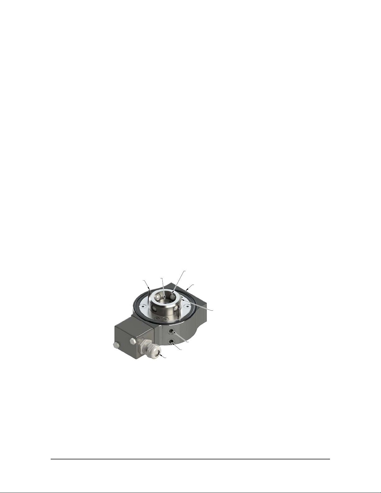
Manual, Robotic Tool Changer, QC‑24Z1
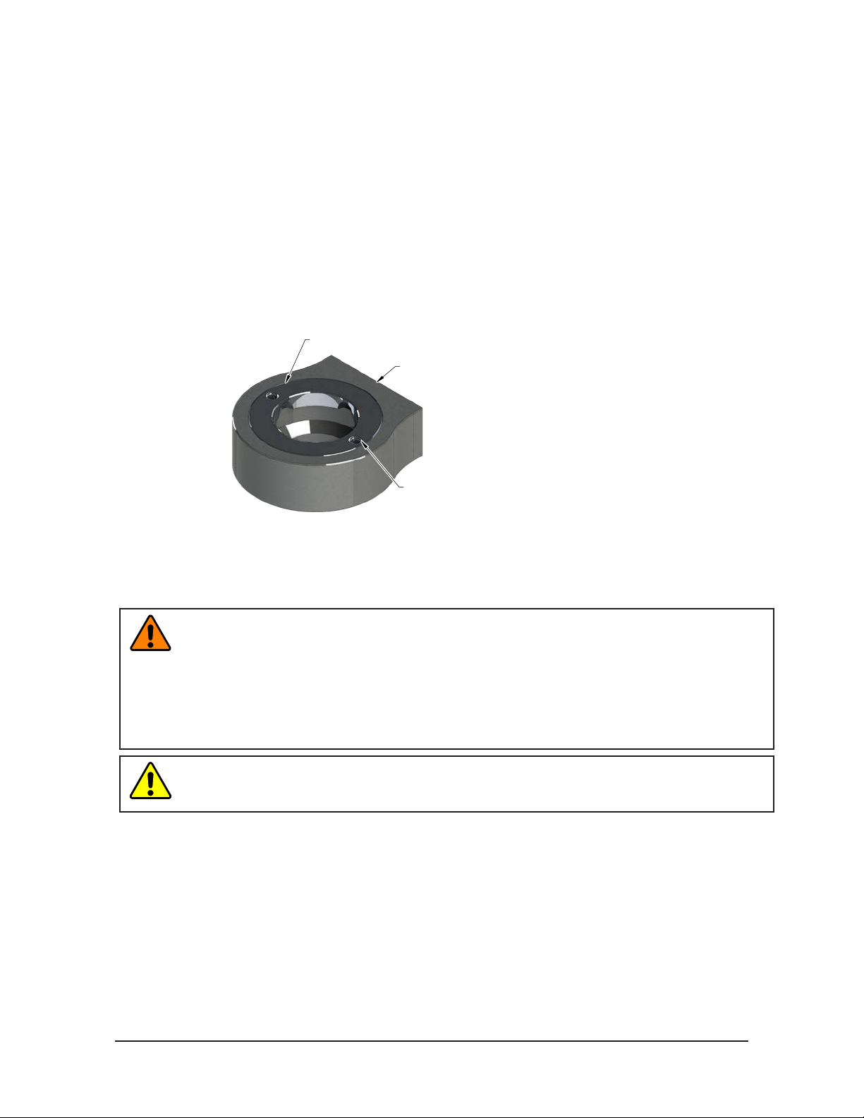
Lock/Unlock Sensor Cable Exit
Mounting Flat for Optional Module
(4) Ball Bearing
(2) Alignment Pin
Document #9610‑20‑3727‑03
2. Product Overview
ATI Tool Changers enhance the versatility of a robot by enabling the use of multiple customer tools, such as:
grippers, vacuum cup tooling, pneumatic and electric motors, weld guns, and more.
The Tool Changer consists of a Master plate, which is attached to the robot arm, and a Tool plate, which is
attached to customer tooling. When the robot picks up the customer tooling, a pneumatically‑driven locking
mechanism couples the two plates. The patented, fail‑safe locking mechanism utilizes a multi‑tapered cam with
ball locking technology to ensure the Tool Changer does not uncouple If the air pressure falls below 60 psi (4.1 bar)
during operation.
The robot can be programmed to select the desired customer tooling by coupling the Master plate to the Tool plate.
Electricity, uid, and other forces of energy transfer to the customer tooling through optional modules that are
attached to the Master and Tool plates. Refer to the ATI website for compatible modules or contact an ATI sales
representative for more details.
2.1 Master Plate Assembly
The Master plate assembly includes the following features:
• A stainless steel body
• A hardened stainless steel locking mechanism (a cam, male coupling, and tungsten
carbide ball bearings)
• Hardened steel alignment pins that mate with bushings on the Tool plate.
• (1) at for mounting an optional module
• Proximity sensor assemblies used to verify the lock/unlock position of the piston and cam
• A mounting pattern for a robot arm or an interface plate
Non‑toxic food grade grease is applied to the cam, male coupling, ball bearings, and pins to enhance
performance and maximize the life of the Master plate.
Figure 2.1—Master Plate Assembly
Cam
Male Coupling
M5 Unlock Air Port
M5 Lock Air Port
Pinnacle Park • 1041 Goodworth Drive • Apex, NC 27539 • Tel: 919.772.0115 • Fax: 919.772.8259 • www.ati‑ia.com
8
Page 9
Manual, Robotic Tool Changer, QC‑24Z1
Mounting Flat for Optional Module
Bearing Race
Document #9610‑20‑3727‑03
2.2 Tool Plate Assembly
The Tool plate includes a stainless steel body and a hardened stainless steel bearing race (refer to
Figure 2.2). Alignment bushings are integrated in the bearing race to ensure proper, repeatable orientation
with the Master plate.
The Tool plate assembly includes the following features:
• A stainless steel body
• A stainless steel bearing race
• Alignment holes that mate with pins on the Master plate
• (1) at for mounting an optional module
• A mounting pattern for customer tooling or a tooling interface plate
Figure 2.2—T ool Plate Assembly
(2) Integrated Alignment Holes
3. Installation
All fasteners used to mount the Tool Changer to the robot and customer’s tooling should be tightened to the
torque values indicated. Additionally, Loctite 7649 primer and removable Loctite 222 must be used on
these fasteners.
WARNING: Do not perform maintenance or repair(s) on the Tool Changer or modules unless
the Tool is safely supported or placed in the tool stand, all energized circuits (e.g. electrical,
air, water, etc.) are turned off, pressurized connections are purged and power is discharged
from the circuits in accordance with the customer specic safety practices and policies. Injury
or equipment damage can occur with the Tool not placed and energized circuits on. Place
the Tool in the tool stand, turn off and discharge all energized circuits, purge all pressurized
connections, and verify all circuits are de‑energized before performing maintenance or
repair(s) on the Tool Changer or modules.
CAUTION: Thread locker applied to fasteners must not be used more than once. Fasteners
might become loose and cause equipment damage. Always apply new thread locker when
reusing fasteners.
Pinnacle Park • 1041 Goodworth Drive • Apex, NC 27539 • Tel: 919.772.0115 • Fax: 919.772.8259 • www.ati‑ia.com
9
Page 10
Manual, Robotic Tool Changer, QC‑24Z1
Document #9610‑20‑3727‑03
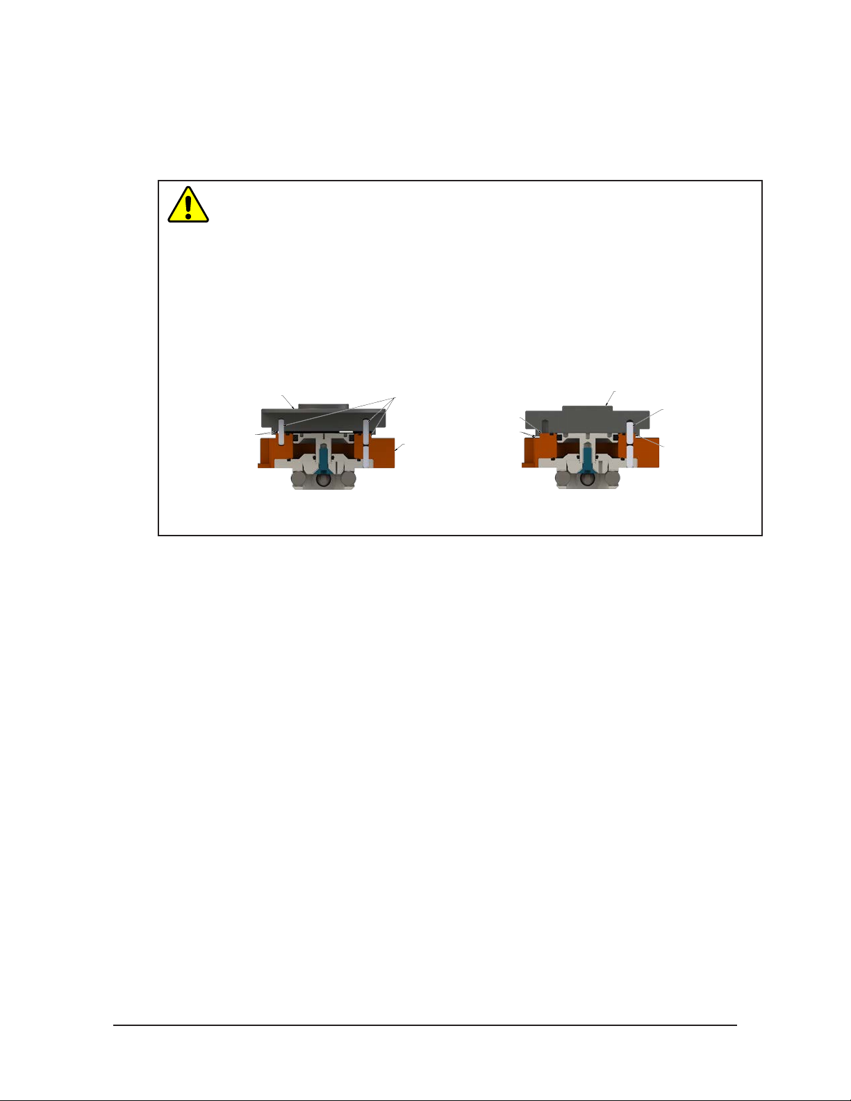
3.1 Master Interface
The Master plate is typically attached to the robot arm. An interface plate can adapt the Master plate to a
specic robot arm. Alignment features (dowel holes and bosses) accurately position and bolt holes secure
the Master plate to the robot arm or an interface plate. Custom interface plates are available from ATI upon
request. (Refer to the Drawing Section for technical information on the mounting features.)
CAUTION: Do not use more than two alignment features when securing a Master plate
to a robot interface plate. Using more than two alignment features can cause damage
to equipment. Use either two dowel pins or a single dowel pin along with a boss/recess
feature to align the Master plate with the robot interface plate.
CAUTION: Do not use dowel pins that are too long that will not allow the interface plate
and the Master body’s boss to mate ush with each other. Using dowel pins that are too
long will cause a gap between the interface plate and the Master body’s boss causing
damage to the equipment. Use the proper size dowel pins that will not extend further
than allowed by the Master body.
Interface Plate
Dowel pins that are too long
can cause a gap between
the interface plate and
boss in the Master plate.
Incorrect Mounting of the Master Plate
A boss and (2) dowel pins
can be difficult to align and
cause damage to the
equipment.
Master Plate
A gap is between the
interface plate
and the flange
of the Master plate.
Correct Mounting of the Master Plate
Flush
Interface Plate
Correct size dowel pin(s)
allows the interface plate
and the boss in the
Master plate to mount flush.
Master Plate
Boss
Note: A dowel pin and a boss/recess
or ((2) dowel pins) are used as
alignment features.
If the customer chooses to design and build an interface plate, consider the following points:
• The interface plate should include bolt holes for mounting and either (2) dowel pins or (1) dowel pin
and a boss for accurate positioning on the robot and Master plate. The dowel and boss features prevent
unwanted rotation. Refer to the robot manual for robot mounting features.
• The thickness of the interface plate must be sufcient to provide the necessary thread engagement for
the mounting bolts.
• Dowel pins must not extend out from the surface of the interface farther than the depth of the dowel
holes in the boss of the Master plate.
• A recess of proper depth and diameter must be machined into the interface plate to correspond with the
boss on the Master plate.
• Mounting bolts that are too long can create a gap between the interface plate and the Master plate,
which can damage the equipment.
• The interface plate must provide rigid mounting to the Master plate.
• The interface plate design must account clearances required for Tool Changer module attachments
and accessories.
Pinnacle Park • 1041 Goodworth Drive • Apex, NC 27539 • Tel: 919.772.0115 • Fax: 919.772.8259 • www.ati‑ia.com
10
Page 11

Manual, Robotic Tool Changer, QC‑24Z1
(4) M4 Socket Flat Head Cap Screw
Document #9610‑20‑3727‑03
3.2 Master Plate Installation
Tools required: 2.5 mm hex key, torque wrench
Supplies required: Clean rag, Loctite® 7649 and 222
1. Wipe down the mounting surfaces with a clean rag.
2. Install the interface plate to the robot arm. Align using the dowel pin(s) and secure with customer
supplied fasteners.
3. If the (4) M4 socket at head cap screws do not have a pre‑applied adhesive. First apply Loctite 7649
then apply Loctite 222 to the threads of the screws.
4. Align the interface plate with the dowel pins on the Master plate.
5. Secure the Master plate to the interface plate with (4) M4 socket at head cap screws using a 2.5 mm hex
key. Tighten 10 in‑lbs (1.13 Nm).
6. Connect the lock and unlock air to the connections on the Master plate. For details on the lock and
unlock air refer to Section 3.8.1—Valve Requirements and Connections for the Locking Mechanism.
7. Connect the lock and unlock sensor cables.
8. If equipped, connect other utilities to the optional modules on the Master plate.
Figure 3.1—Typical Master Plate Installation
Interface Plate
(Customer Supplied)
Interface Plate Fastener
(Customer Supplied)
Master Plate
3.3 Master Plate Removal
Tools required: 2.5 mm hex key
1. Place the Tool in a secure location.
2. Uncouple the Master and Tool plates.
3. Turn off and de‑energize all energized circuits (for example: electrical, pneumatic, and
hydraulic circuits).
4. If equipped, disconnect all utilities (for example: electrical, pneumatic, hydraulic).
5. Disconnect the lock and unlock sensor cables.
6. Using a 2.5 mm hex key, loosen the (4) M4 socket at head cap screws in the Master plate so that the
Master plate can be removed from the interface plate. Note: The interface plate is not required to be
removed from the robot.
Pinnacle Park • 1041 Goodworth Drive • Apex, NC 27539 • Tel: 919.772.0115 • Fax: 919.772.8259 • www.ati‑ia.com
11
Page 12

Manual, Robotic Tool Changer, QC‑24Z1
Correct Mounting of Tool Plate
Interface Plate
Incorrect Mounting of Tool Plate
Document #9610‑20‑3727‑03
3.4 Tool Interface
The Tool plate is attached to the customer’s tooling. An interface plate can adapt the Tool plate to customer
tooling. Alignment features (dowel holes and a recess) accurately position and bolt holes to secure the Tool
plate to customer tooling. Custom interface plates can be supplied by ATI (refer to the application drawing).
CAUTION: Do not use more than two alignment features when securing a Tool plate
to an interface plate. Using more than two alignment features can cause damage to
equipment. Use either two dowel pins or a single dowel pin, along with a boss/recess
feature to align the Tool plate with the interface plate.
CAUTION: Do not use dowel pins that are too long or do not allow the interface plate
and Tool body to mate ush. Using dowel pins that are too long will cause a gap
between the interface plate and Tool body and damage the equipment. Use dowel pins
that will not extend further than allowed by the Tool body.
Boss and two dowel pins
as alignment features can be
difficult to align and can
damage equipment.
Dowel pins
are too long and
cause a gap between
interface plate and Tool.
Tool Plate
Gap
single dowel pin along with a
proper size allowing
interface plate and Tool
Plate to mount flush.
Two dowel pins (or a
boss/recess) used as
alignment features.
Dowel pins are
Interface Plate
Tool Plate
If the customer chooses to design and build a tool interface plate, consider the following points:
• The interface plate should include bolt holes for mounting and either two dowel pins or a dowel
pin and a boss for accurate positioning on the customer tooling and Tool plate. The dowel and boss
features prevent unwanted rotation.
• Dowel pins must not extend out from the surface of the interface plate farther than the depth of the
dowel holes in the Tool plate.
• The thickness of the interface plate must be sufcient to provide the necessary thread engagement for
the mounting bolts. Fasteners should meet minimum recommended engagement lengths while not
exceeding the maximum available thread depth. Use of bolts that are too long can cause damage to the
tool side changer.
• The plate design must account for clearances required for Tool Changer module attachments
and accessories.
• If a boss is to be used on the interface plate, a boss of proper height and diameter must be machined
into the interface plate to correspond with the recess in the Tool plate.
• The interface plate must have a hole in its center for manually returning the locking mechanism to
the unlocked position under adverse conditions (i.e. unintended loss of power and/or air pressure).
The center access hole with a minimum diameter of the 1” (25.4 mm) prevents debris from the
contaminating the locking mechanism. Greater protection is provided by leaving the race cover and
grommet in place.
Pinnacle Park • 1041 Goodworth Drive • Apex, NC 27539 • Tel: 919.772.0115 • Fax: 919.772.8259 • www.ati‑ia.com
12
Page 13

Manual, Robotic Tool Changer, QC‑24Z1
(2) Dowel Pin (Customer Supplied)
Document #9610‑20‑3727‑03
3.5 Tool Plate Installation
Tools required: hex keys, torque wrench
Supplies required: Clean rag, Loctite 7649 and 222
1. Wipe down the mounting surfaces with a clean rag.
2. If required, install the tooling interface plate to the customer tooling, align using the boss and dowel
pin(s). Secure with customer supplied fasteners.
3. Align the dowel pin in the tool interface plate or customer tooling to the corresponding hole in
the T ool plate.
4. First apply Loctite 7649 then apply Loctite 222 to the threads of the customer supplied
fasteners, (4) M6 screws.
5. Secure the Tool plate to the tool interface plate or customer tooling with (4) M6 screws using
appropriate hex key.
6. Connect utilities to the optional modules on the Tool plate.
7. Safely resume normal operation.
Figure 3.2—Standard Tool Plate Installation
Tool Plate
(4) M6 Screw (Customer Supplied)
3.6 Tool Plate Removal
Tools required: hex keys, wrenches, or screwdrivers
1. Place the Tool in a secure location.
2. If equipped, disconnect all utilities (for example: electrical, pneumatic, hydraulic).
3. Using appropriate hex key, remove the (4) M6 fasteners, connecting the Tool plate to the tool
interface plate.
4. Remove the Tool plate.
Pinnacle Park • 1041 Goodworth Drive • Apex, NC 27539 • Tel: 919.772.0115 • Fax: 919.772.8259 • www.ati‑ia.com
13
Page 14

Manual, Robotic Tool Changer, QC‑24Z1
(4) M4 Socket Head Cap Screw
Document #9610‑20‑3727‑03
3.7 Optional Module
The optional modules are typically installed on the Tool Changers by ATI prior to shipment. The following
steps outline eld installation or removal as required. Tool Changers are compatible with many different
types of modules. Some modules will require an adapter plate to be installed to the Tool Changer.
3.7.1 Optional Module Installation
Tools required: hex keys, torque wrench
Supplies required: Loctite 7649 and 222
1. Place the Tool in a secure location.
2. Uncouple the Master and Tool plates.
3. Turn off and de‑energize all energized circuits (for example: electrical, pneumatic, and
hydraulic circuits).
4. Align the (2) dowel pins, if equipped, on the each module to corresponding holes on Flat of the
Master or Tool plate as shown in Figure 3.3.
5. If not using fasteners with pre‑applied adhesive, rst apply Loctite 7649 then apply Loctie 222
to the (4) mounting fasteners on the each module.
6. Place the silicone gasket between the optional module and Tool Changer plate.
7. Secure the optional modules to the Tool Changer with mounting fasteners.
8. Remove the all protective caps, plugs, tape, etc. from the module prior to operation.
9. Connect any cables, air line, etc. (if required)
10. Safely resume normal operation.
Figure 3.3—Optional Module Installation
Master Plate
Silicone Gasket
Optional Module
(FR2ZF5G3-M)
Tool Plate
Silicone Gasket
Optional Module
(FR2ZF5G3-T)
(4) M4 Socket Head Cap Screw
Pinnacle Park • 1041 Goodworth Drive • Apex, NC 27539 • Tel: 919.772.0115 • Fax: 919.772.8259 • www.ati‑ia.com
14
Page 15

Manual, Robotic Tool Changer, QC‑24Z1
4 or 5-way Valve
Supply Clean, Dry,
Non-lubricated Air
60 – 100 psi (4.1 –6.9 Bar
)
Exhaust
Open to Atmosphere
Lock Port
Unlock Port
Document #9610‑20‑3727‑03
3.7.2 Optional Module Removal
Refer to Figure 3.3
Tools required: hex keys
1. Place the Tool in a secure location.
2. Uncouple the Master and Tool plates.
3. Turn off and de‑energize all energized circuits (for example: electrical, pneumatic, and
hydraulic circuits).
4. Disconnect any cables, air line, etc. If required.
5. Supporting the module, remove the (4) mounting fasteners from the each module.
6. Remove the module and gasket from the Tool Changer plate.
3.8 Pneumatic Connections
The air supply used for coupling and uncoupling the Tool Changer should be clean, dry, and non‑lubricated.
A supply pressure in the range of the 60 to 100 psi is acceptable for operation of the locking mechanism,
with a setting of the 80 psi suggested. The air should be ltered 40 micron or better.
CAUTION: Do not use the Tool Changer in a fail‑safe condition. Do not transport the
Tool Changer in a fail‑safe condition. Possible damage to the locking mechanism
could occur. Re‑establish air pressure to the Tool Changer before returning to
normal operations.
3.8.1 Valve Requirements and Connections for the Locking Mechanism
It is required that a customer supplied 2‑position 4‑way or 5‑way valve be used to actuate the
locking mechanism in the Master plate. It is imperative that when air is supplied to the lock or
unlock port on the Master plate, that the opposite port be vented to atmosphere (for example: when
air is supplied to the lock port, the unlock port must be open to the atmosphere.) Failure to vent
trapped air or vacuum on the inactive port may inhibit proper shuttling of the valve and prevent
coupling/uncoupling from the occurring.
CAUTION: The locking mechanism will not function properly when connected
to a single 3‑way valve as this type of valve is incapable of venting trapped air
pressure from the within the Tool Changer. This could result in damage to the
product, attached tooling, or personnel. Connect the lock and unlock supply air
to a 2‑position 4‑way or 5‑way valve.
Figure 3.4—Lock and Unlock Pneumatic Connections
Pinnacle Park • 1041 Goodworth Drive • Apex, NC 27539 • Tel: 919.772.0115 • Fax: 919.772.8259 • www.ati‑ia.com
15
Page 16

Manual, Robotic Tool Changer, QC‑24Z1
(3) Blue
Brown (1)
(4) Black
Brown (1)
Black (4)
Blue (3)
+Vs
Output
0 V
NPN
Z
Connector
NPN (Current Sinking)
Document #9610‑20‑3727‑03
3.9 Electrical Connections
Integrated lock/unlock sensors are available.
3.9.1 PNP Type Lock and Unlock Sensors (-SM sensor designation)
Description Value
Voltage Supply Range 10‑30VDC
Output Circuit PNP make function (NO)
Figure 3.5—PNP Type Lock, Unlock and RTL Sensors
Table 3.1—PNP (Current Sourcing)
PNP (Current Sourcing)
Brown (1)
Black (4)
PNP
Blue (3)
3.9.2 NPN Type Lock and Unlock Sensors (-SP sensor designation)
Description Value
Voltage Supply Range 10‑30VDC
Output Circuit NPN make function (NO)
Figure 3.6—NPN Type Lock, Unlock and RTL Sensors
Z
Connector
+Vs
Output
Brown (1)
0 V
Table 3.2—NPN (Current Sinking)
(4) Black
(3) Blue
Pinnacle Park • 1041 Goodworth Drive • Apex, NC 27539 • Tel: 919.772.0115 • Fax: 919.772.8259 • www.ati‑ia.com
16
Page 17

Manual, Robotic Tool Changer, QC‑24Z1
Document #9610‑20‑3727‑03
4. Operation
The Master plate locking mechanism is pneumatically driven to couple and uncouple with the Tool
plate bearing race.
CAUTION: Operation of the Tool Changer is dependent on the maintaining an air pressure
of 60 to 100 psi (4.1–6.9 bar). Damage to the locking mechanism could occur. Robot motion
must be halted If the air supply pressure drops below 60 psi (4.1 bar).
NOTICE: All Tool Changers are lubricated prior to shipment. The customer must apply additional
lubricant to the locking mechanism components and alignment pins prior to operation. Tubes of
lubricant for this purpose are shipped with every Tool Changer. Standard Tool Changers require
food grade grease.
Coupling should occur with the Master plate in the No‑Touch™ locking zone. As coupling occurs, the Master plate
should pull the Tool plate into the locked position.
Program the robot to minimize misalignment during coupling and uncoupling. Greater offsets can be
accommodated by the Master and Tool plates but will increase wear. Misalignments can be caused by improper tool
stand design. Refer to Tool Storage Considerations section.
Figure 4.1—OffsetDenitions(ImageforReferenceOnly)
Master Plate
Twisting Offset
(About Z)
Tool Plate
Z
Y
X, Y, and Z Offset
X
Cocking Offset
(About X and Y)
Table 4.1—Maximum Recommended Offsets Prior to Coupling
Model
QC‑24Z1
No‑Touch™ Zone
Z Offset (Max)
1
(mm)
0.08 in (2.0 mm) ±0.04 in, (1.0 mm) 0.8 ±0.08 in (2.0 mm)
X and Y Offset (Max)
(mm)
Notes:
1. Maximum values shown. Decreasing actual values will minimize wear during coupling/uncoupling.
2. Actual allowable values may be higher in some cases but higher offsets will increase wear during coupling.
2
Cocking Offset (Max)
(degrees)
Twisting Offset (Max)
(degrees)
Pinnacle Park • 1041 Goodworth Drive • Apex, NC 27539 • Tel: 919.772.0115 • Fax: 919.772.8259 • www.ati‑ia.com
17
Page 18

Manual, Robotic Tool Changer, QC‑24Z1
Document #9610‑20‑3727‑03
4.1 Conditions for Coupling
CAUTION: The locking mechanism must be in the unlock position when attempting to
couple the Tool Changer. Failure to adhere to this condition may result in damage to
the unit and/or the robot.
1. Position the Master plate above the Tool plate with the air supplied to the Unlock Port (if equipped, the
Unlock sensor indicates the Tool Changer is Unlocked).
2. Move the Master plate toward the Tool plate so that the (2) alignment pins enter the alignment holes on
the opposite plate. Program the robot so that the Master plate and Tool plate are aligned axially and are
parallel to each other (as closely as possible). This will minimize Tool movement and subsequent wear
during lock‑up.
CAUTION: No‑Touch™ locking technology allows the unit to couple with a separation
distance between the Master and Tool. Direct contact of the Master and Tool mating
surfaces is not suggested or required prior to coupling. Contact may result in damage
to the unit and/or the robot.
3. When the (2) faces are within the specied No‑Touch™ distance, release the pressure from the Unlock
port and supply air to the Lock port. The Tool plate is drawn toward the Master plate and coupled. Air
must be maintained on the Lock Port during operation to assure rigid coupling (if equipped, the Lock
sensor indicates the Tool Changer is in the Locked position).
4. A sufcient delay must be programmed between locking valve actuation and robot motion so that the
locking process is complete before moving the robot.
CAUTION: If air pressure is lost during operation, ATI’s patented fail‑safe design
prevents the Tool plate from being released. Do not use the Tool Changer in a fail‑safe
condition. Re‑establish air pressure and ensure the Tool Changer is in a secure lock
position before returning to normal operations.
Pinnacle Park • 1041 Goodworth Drive • Apex, NC 27539 • Tel: 919.772.0115 • Fax: 919.772.8259 • www.ati‑ia.com
18
Page 19

Manual, Robotic Tool Changer, QC‑24Z1
Document #9610‑20‑3727‑03
5. A sufcient delay must be programmed between locking valve actuation and robot motion so that the
locking process is complete before moving the robot. If equipped with lock and unlock sensors, the lock
signal should read “ON” (true) and the unlock signal should read “OFF” (false).
NOTICE: If the locking mechanism has been actuated and both the lock and unlock signals are
OFF, then a “missed tool” condition has occurred (for example, the Tool is not in the stand or is
not positioned properly). in this case an error should be generated and the robot program
halted. The situation requires manual inspection to determine the cause of the problem. Some
congurations will require a manual unlock of the Master plate before attempting coupling, refer
to the Control/Signal Module Manual for instructions.
NOTICE: The locking mechanism must be in the unlock state before another attempt is made to
couple or damage could occur to the robot and/or the Tool Changer.
4.2 Fail-Safe Operation
A fail‑safe condition occurs when there is an unintended loss of lock air pressure to the Master plate. When
air pressure is lost, the Tool Changer relaxes and there may be a slight separation between the Master
and Tool plates. The lock sensor may indicate that the unit is not locked. ATI’s patented fail‑safe feature
utilizes a multi‑tapered cam to trap the ball bearings and prevent an unintended release of the Tool plate.
Positional accuracy of the tooling is not maintained during this fail‑safe condition. Do not operate the Tool
Changer in the fail‑safe condition. If the source air is lost to the unit, movement should be halted until air
pressure is restored.
After air pressure is re‑established to the Master plate, the locking mechanism will energize and securely
lock the Master and Tool plates together. in some cases when the load on the tool changer is signicantly off
center, it may be necessary to position load underneath the tool changer or return the tool to the tool storage
location to ensure a secure lock condition. If equipped, make sure the lock sensor indicates the Tool Changer
is in the locked position before resuming normal operations. Consult your Control/Signal Module Manual
for specic error recovery information.
CAUTION: Do not use the Tool Changer in a fail‑safe condition. Damage to the locking
mechanism could occur. Re‑establish air pressure and ensure the Tool Changer is in a
secure lock position before returning to normal operations.
4.3 Conditions for Uncoupling
1. Position Tool plate in the tool stand so that there is little or no contact force between the Tool plate
and tool stand.
2. Release air on the Lock port and apply air to the Unlock Port (If equipped, the Unlock sensor will
indicate the Tool Changer is in the Unlocked position).
NOTICE: The air will cause the locking mechanism to be released and the weight of the Tool
plate and attached tooling will assist in its removal. The Tool weight assists in the uncoupling If
the Tool is released in the vertical position only.
3. A sufcient delay must be programmed between unlocking valve actuation and robot motion, so that
unlocking process is complete and the Tool plate is fully released before moving the robot.
4. Move the Master plate axially away from the Tool plate.
5. In automated Tool change applications, it is recommended that a Tool presence sensor(s) be used in the
tool stand to verify that the Tool is present and that the Tool remains in place as the robot moves away
after unlocking process.
4.4 ToolIdentication
When using multiple Tools, it is good practice to implement a Tool‑ID system that identies each Tool
with a unique code. Tool‑ID can be used to verify that the robot has picked up the proper Tool. Modules
with Tool‑ID are available for purchase through the ATI website. Go to http://www.ati‑ia.com/products/
toolchanger/tool_changer_modules.aspx for products available or contact ATI for assistance.
Pinnacle Park • 1041 Goodworth Drive • Apex, NC 27539 • Tel: 919.772.0115 • Fax: 919.772.8259 • www.ati‑ia.com
19
Page 20

Manual, Robotic Tool Changer, QC‑24Z1
Document #9610‑20‑3727‑03
4.5 Tool Storage Considerations
NOTICE: Tool stand design is critical to operation of the Tool Changer. Improperly designed tool
stands can cause jamming and excessive wear of the Tool Changer components.
Tool plates with customer tooling attached may be stored in a tool stand. ATI provides compatible tool
stands designed for durability, longevity, and maximum adaptability to t most customers’ applications. The
ATI TSS (Tool Stand Small) system is compatible with ATI Tool Changer sizes QC‑001 to QC‑41. The TSS
systems can be equipped with horizontal modules, clamp modules, and different types of tool sensing. Two
mounting styles are available: a pin and bushing style and a pin and rack style. Visit the ATI Web Site http://
www.ati‑ia.com/products/toolchanger/toolstand/small/SmallStand.aspx for products available or contact ATI
for assistance.
If the customer is supplying the tool stand, they must provide a xed, repeatable, level, and stable position
for tool pick‑up and drop‑off. The tool stand must support the weight of the Tool Changer Tool plate,
interface plate, optional modules, cables, hoses, and customer tooling without allowing deection in the
excess of the offsets.
The tool should be hanging vertically in the tool stand so that gravity assists to uncouple the Tool
plate from the Master plate during unlocking. It is possible to design tool stands that hold tools in the
horizontal position, but the necessary compliance must be provided during coupling and uncoupling.
“Horizontal‑Position” tool stands cause more wear on the locking mechanism and locating features of both
the Tool and tool stand.
A variety of the methods may be used to position Tool in the tool stand. A common method is to use
tapered alignment pins and bushings. Robot programming and positional repeatability are vital in the Tool
pick‑up and drop‑off.
A sensor that detects the presence of a Tool in the tool stand is recommended. The sensor may be used prior
to coupling to ensure there is a Tool properly seated in the stand. Sensors may also be used as the robot starts
to move away after uncoupling. Sensors provide an added safety measure If the Tool becomes jammed in the
stand or if the Tool fails to release from the robot.
Proximity sensors should be positioned so that the sensing face is vertical to prevent metal shavings, weld
spatter, or other debris from the falling on the sensor and creating false readings.
Tool stand debris shields can cover Tools and modules to protect them in the dirty environments, such as
grinding or welding. Alternatively, positioning tool stands in the areas shielded from the weld spatter, uids,
adhesives, or other debris would eliminate the need for debris shields.
Pinnacle Park • 1041 Goodworth Drive • Apex, NC 27539 • Tel: 919.772.0115 • Fax: 919.772.8259 • www.ati‑ia.com
20
Page 21

Manual, Robotic Tool Changer, QC‑24Z1
Document #9610‑20‑3727‑03
5. Maintenance
WARNING: Do not perform maintenance or repair(s) on the Tool Changer or modules unless
the Tool is safely supported or placed in the tool stand, all energized circuits (e.g. electrical,
air, water, etc.) are turned off, pressurized connections are purged and power is discharged
from the circuits in accordance with the customer specic safety practices and policies. Injury
or equipment damage can occur with the Tool not placed and energized circuits on. Place
the Tool in the tool stand, turn off and discharge all energized circuits, purge all pressurized
connections, and verify all circuits are de‑energized before performing maintenance or
repair(s) on the Tool Changer or modules.
NOTICE: The cleanliness of the work environment strongly inuences the trouble free operation of
the Tool Changer. The dirtier the environment, the greater the need for protection against debris.
Protection of the entire EOAT, the Master, the Tool and all of the modules may be necessary. Protective
measures include the following:
Placement of the tool stands away from the debris generators.
• Covers incorporated into the tool stands.
• Guards, deectors, air curtains, and similar devices built into the EOAT
5.1 Preventive Maintenance
A visual inspection and preventive maintenance schedule is provided in table below. Detailed assembly drawings are
provided inSection 9—Drawings of this manual. Refer to module sections for detailed preventive maintenance steps for
all utility modules.
and the tool stand.
Table 5.1—Preventive Maintenance Check List
Application(s) Tool Change Frequency Inspection Schedule
General Usage Material Handling Docking Station
Welding/Servo/Deburring, Foundry Operations (Dirty Environments) All Weekly
Checklist
Balls/Alignment Pins/Holes/Bearing Race
г Inspect for lubrication and wear. JET LUBE® FMG is suggested for locking mechanism and alignment pin
lubrication. Over time, lubricants can become contaminated with process debris. Therefore, it is recommended
to thoroughly clean the existing grease and replace with new as needed. See
Lubrication of the Locking Mechanism and Alignment Pins.
г Inspect for excessive alignment pin/bushing wear, may be an indication of the poor robot position during
pickup/drop‑off. Adjust robot position as needed.
г Inspect for wear on the ball bearings/bearing race, may be an indication of the excessive loading.
Mounting Hardware/Interface Connections
г Inspect for proper torque and interference or wear, abrasions, cuts of hoses, and electrical cables. Tighten and
correct as required. Refer to Section 3—Installation.
Seals (Modules)
г Inspect for wear, abrasion, and cuts. Refer to Section 6.2.2—V‑ring Seal Inspection and Replacement.
Sensors and Cables
г Inspect sensor cable connectors for tightness, if loose tighten connections.
г Inspect sensor cables for any damage, cuts, and abrasion. Replace as necessary. Refer to Section 6.2—
Service Procedures.
Electrical Contacts/Pin Block (Modules)
г Inspect for damage, debris, and stuck/burnt pins. Clean pin blocks as required, refer to Section 5.3—Pin Block
Inspection and Cleaning.
> 1 per minute Weekly
< 1 per minute Monthly
Section 5.2—Cleaning and
Pinnacle Park • 1041 Goodworth Drive • Apex, NC 27539 • Tel: 919.772.0115 • Fax: 919.772.8259 • www.ati‑ia.com
21
Page 22

Manual, Robotic Tool Changer, QC‑24Z1
Document #9610‑20‑3727‑03
5.2 Cleaning and Lubrication of the Locking Mechanism and Alignment Pins
Supplies required: Clean rag, food grade grease
1. Place the Tool in a secure location.
2. Uncouple the Master and Tool plates.
3. Turn off and de‑energize all energized circuits (for example: electrical, pneumatic, and
hydraulic circuits).
4. Use a clean rag to thoroughly remove any lubricant and debris from the ball bearings, male coupling,
cam, and alignment pins.
Figure 5.1—Cleaning Ball Bearings and Outer Surfaces of Male Coupling
5. Use a clean rag to thoroughly remove any lubricant and debris from the inner surface of the male
coupling and cam.
Figure 5.2—Cleaning Ball Bearings, Cam and Inner Surfaces of Male Coupling
Pinnacle Park • 1041 Goodworth Drive • Apex, NC 27539 • Tel: 919.772.0115 • Fax: 919.772.8259 • www.ati‑ia.com
22
Page 23

Manual, Robotic Tool Changer, QC‑24Z1
Apply lubricant on inner
surface of male coupling.
Apply lubricant on the following:
Bushing Surfaces
Document #9610‑20‑3727‑03
6. Check each ball bearing to make sure it moves freely in the male coupling. Additional cleaning may be
necessary to free up any ball bearings that are sticking in place.
Figure 5.3—Check Ball Bearing Movement
7. Apply a liberal coating of the lubricant to the ball bearings, the male coupling (inside and out), and the
alignment pins.
Figure 5.4—Apply Lubricant to Locking Mechanism
Alignment Pins
Ball Bearings
Male Coupling (Outer Surface)
8. Use a clean rag to thoroughly remove any lubricant and debris from the Tool plate bearing
race and bushings.
NOTICE: No application of the lubrication is necessary on the Tool plate components.
9. Safely resume normal operation.
Figure 5.5—Clean Tool Plate Surfaces of Locking Mechanism
Clean Bearing
Race and
Pinnacle Park • 1041 Goodworth Drive • Apex, NC 27539 • Tel: 919.772.0115 • Fax: 919.772.8259 • www.ati‑ia.com
23
Page 24

Manual, Robotic Tool Changer, QC‑24Z1
Tool Module Pin Block
Master Module Pin Block
Darkened Pins
Document #9610‑20‑3727‑03
5.3 Pin Block Inspection and Cleaning
Tools required: Nylon Brush (ATI Part Number 3690‑0000064‑60)
1. Place the Tool in a secure location.
2. Uncouple the Master and Tool plates.
3. Turn off and de‑energize all energized circuits (for example: electrical, pneumatic, and
hydraulic circuits).
4. Inspect the Master and Tool pin blocks for debris or darkened pins.
Figure 5.6—Inspect Master and Tool Pin Blocks
Note: Pin blocks shown are for
illustrative purposes only.
Weld Debris
5. If the debris or darkened pins are present, use a vacuum to remove the debris, and clean using a nylon
brush (ATI Part Number 3690‑0000064‑60).
NOTICE: Do not use an abrasive media and/or cleaners or solvents to clean the contact pins.
Using abrasive media and/or cleaners or solvents will cause damage to the contact surface or
cause pins to stick. Clean contact surfaces with a vacuum or non‑abrasive media such as a
nylon brush (ATI Part Number 3690‑0000064‑60).
Figure 5.7—Clean Pin Blocks with a Nylon Brush
6. Inspect the Master and Tool pin blocks for stuck pins or pin block damage.
Figure 5.8—Stuck Pin and Pin Block Damage
Note: Pin blocks shown are for
illustrative purposes only.
Stuck Pins
Pin Block Damage
7. If the pins become stuck or if there is damage to the pin block, contact ATI for either a possible pin
replacement procedure or module replacement.
8. Safely resume normal operation.
Pinnacle Park • 1041 Goodworth Drive • Apex, NC 27539 • Tel: 919.772.0115 • Fax: 919.772.8259 • www.ati‑ia.com
24
Page 25

Manual, Robotic Tool Changer, QC‑24Z1
Document #9610‑20‑3727‑03
6. Troubleshooting and Service Procedures
The following section provides troubleshooting and service information to help diagnose conditions and repair
the T ool Changer.
WARNING: Do not perform maintenance or repair(s) on the Tool Changer or modules unless
the Tool is safely supported or placed in the tool stand, all energized circuits (e.g. electrical,
air, water, etc.) are turned off, pressurized connections are purged and power is discharged
from the circuits in accordance with the customer’s safety practices and policies. Injury or
equipment damage can occur with the Tool not placed and energized circuits on. Place the
Tool in the tool stand, turn off and discharge all energized circuits, purge all pressurized
connections, and verify all circuits are de‑energized before performing maintenance or
repair(s) on the Tool Changer or modules.
6.1 Troubleshooting
Check these conditions for all symptoms prior to troubleshooting:
• Proper pneumatic and electrical connections have been made to the Tool Changer.
• Air is supplied at a minimum of the 60 psi (4.1 Bar).
• No air or vacuum can be trapped in a de‑energized lock or unlock port (pressure must be vented
to atmosphere).
Table 6.1—Troubleshooting Procedures
Symptom Cause Resolution
The ball bearings and/or
cam are not moving freely in
the male coupling.
The control module is not
Unit will
not lock or unlock
Unit is locked but
lock signal does not
read “on” (true).
Unit is unlocked but
Unlock signal does
not read “on” (true).
Units Equipped with Electrical Modules
Contamination in the
electrical contacts
operating correctly.
The Master plate and Tool plate are
not within the specied No‑Touch
zone when attempting to lock.
Lock sensor/cable is damaged.
Lock sensor is out of the position.
Unlock sensor/cable is damaged.
Unlock sensor is out of the position.
V‑ring seal damaged.
Clean and lubricate as needed to restore
smooth operation (see
and Lubrication of the Locking Mechanism and
Alignment Pins)
Check the troubleshooting section of the manual for
the specic module.
Check that the Tool is properly seated in the Tool
stand. Refer to
Re‑teach the robot to bring the Master
plate and Tool plate closer together prior to
attempting to lock.
Replace the lock sensor sub‑assembly as
necessary. Refer to
Unlock Sensor Replacement.
Replace the lock sensor sub‑assembly as
necessary. Refer to
Unlock Sensor Replacement.
Replace the unlock sensor sub‑assembly as
necessary. Refer to
Unlock Sensor Replacement.
Replace the unlock sensor sub‑assembly as
necessary. Refer to
Unlock Sensor Replacement.
Inspect V‑ring seal for damage, replace damaged
seal. Refer to
and Replacement.
Section 4.4—Tool Identication.
Section 6.2.2—V‑ring Seal Inspection
Section 5.2—Cleaning
Section 6.2.1—Lock and
Section 6.2.1—Lock and
Section 6.2.1—Lock and
Section 6.2.1—Lock and
Pinnacle Park • 1041 Goodworth Drive • Apex, NC 27539 • Tel: 919.772.0115 • Fax: 919.772.8259 • www.ati‑ia.com
25
Page 26

Manual, Robotic Tool Changer, QC‑24Z1
Cap Screw
(2) M4 Hex Head
Sensor
O-ring
Master Plate
Document #9610‑20‑3727‑03
6.2 Service Procedures
Component replacement and adjustment procedures are provided in following section.
6.2.1 Lock and Unlock Sensor Replacement
The proximity sensors are dependable and normally do not need to be replaced. Exhaust all other
possible solutions, before choosing to replace the proximity sensors, including: checking continuity,
air supply, lubrication, and pneumatic components prior to replacing the sensor.
Refer to Figure 6.1.
Parts required: Refer to Section 7—Serviceable Parts
Tools required: 2.5 mm hex key, 7 mm wrench, torque wrench
Supplies required: Loctite 7649 and 222
1. Place the Tool in a secure location.
2. Uncouple the Master and Tool plates.
3. Turn off and de‑energize all energized circuits (e.g. electrical, air, water, etc.).
4. Disconnect the sensor pigtail for the sensor being replaced.
5. Loosen the cord grip dome nut that provides an exit for the sensor cables.
6. Remove the (2) M4 hex head cap screws that secure the sensor cover to the Master plate
using a 7 mm wrench.
7. Carefully remove the sensor cover allowing the sensor cables to slide through the cord grip until
the sensors can be accessed. Note: the O‑ring for the sensor cover may have to be repositioned
into the channel in the sensor cover.
8. Remove the M3 socket head cap screw that secure the lock and/or unlock sensor assembly to
the Tool Changer body using a 2.5 mm hex key.
9. Pull the sensor assembly straight out from the Tool Changer body. There is an O‑ring around
the sensor between the assembly and the Tool Changer body, ensure O‑ring came off with old
sensor before continuing.
10. Slide the lock and/or unlock sensor cable out of the cord grip on the sensor cover. Discard the
removed sensor assembly.
CAUTION: The lock and unlock sensor assemblies are precision
aligned and permanently assembled at the factory. Do not attempt to
disassemble and rebuild.
Figure 6.1—Lock and Unlock Sensor Assembly Replacement
Cover
Cap Screw
Pinnacle Park • 1041 Goodworth Drive • Apex, NC 27539 • Tel: 919.772.0115 • Fax: 919.772.8259 • www.ati‑ia.com
Cord Grip
Dome Nut
M3 Socket Head
Lock Sensor
Assembly
O-ring
Unlock Sensor
Assembly
26
Page 27

Manual, Robotic Tool Changer, QC‑24Z1
Document #9610‑20‑3727‑03
11. Route the new lock and/or unlock sensor cable through the cord grip on the sensor cover.
12. Insert the lock and/or unlock sensor assembly into the Tool Changer body as shown in
Figure 6.1. Ensure that new O‑ring is in place before inserting sensor.
13. Secure the sensor assembly with a M3 socket head cap screw using a 2.5 mm hex key. Tighten
to 12 in‑lbs (0.9 Nm).
14. Carefully install the sensor cover allowing the sensor cables to slide through the cord grip until
the cover in place. Note: the O‑ring for the sensor cover may have to be repositioned into the
channel in the sensor cover.
15. Tighten the cord grip dome nut that provides an exit for the sensor cables.
16. Apply Loctite 7649 and 222 to the (2) M4 hex head cap screws.
17. Install the (2) M4 hex head cap screws that secure the sensor cover to the Master plate using a
7 mm wrench. Tighten to 10 in‑lbs (1.13 Nm).
18. Connect the sensor pigtail for the replaced sensor.
19. Safely resume normal operation.
Pinnacle Park • 1041 Goodworth Drive • Apex, NC 27539 • Tel: 919.772.0115 • Fax: 919.772.8259 • www.ati‑ia.com
27
Page 28

Manual, Robotic Tool Changer, QC‑24Z1
Document #9610‑20‑3727‑03
6.2.2 V-ring Seal Inspection and Replacement
The seal protects the electrical connection between the Master and Tool module. If the seal
becomes worn or damaged, replace the seal.
1. Place the Tool in a secure location.
2. Uncouple the Master and Tool plates.
3. Turn off and de‑energize all energized circuits (for example: electrical, pneumatic, and
hydraulic circuits).
4. To remove the existing seal, pinch the edge of the seal, and pull the seal away from the pin
block on the Master module.
5. To install a new seal, stretch the new seal over the shoulder of the pin block.
6. Push the seal hub down against the pin block.
7. Safely resume normal operation.
Figure 6.2—V-ring Seal Replacement
V‑ring Seal
Stretch seal over shoulder of pin block
and push seal hub down against
the pin block with finger tip
V‑ring Seal
Pinch edge of seal with
fingers and gently pull
away from pin block
Pinnacle Park • 1041 Goodworth Drive • Apex, NC 27539 • Tel: 919.772.0115 • Fax: 919.772.8259 • www.ati‑ia.com
28
Page 29

Manual, Robotic Tool Changer, QC‑24Z1
5
Document #9610‑20‑3727‑03
7. Serviceable Parts
7.1 Master Plate
3
2
4
2
5
6
Table 7.1—QC-24MZ1 Master Plate
Item No. Qty Part Number Description
9120‑024MZ1‑000‑SM
1 1
9120‑024MZ1‑000‑SP
2 2
3 1
4 1 3700‑20‑10867 QC‑24MZ1 Sensor Cover Block
5 2 3500‑0862035‑23 M4‑0.7 X 35 Hex Head Cap Screw, SS, Self Sealing, Viton
6 1 3620‑5302700‑20 Strain Relief, M16‑1.5, Dome Top, (2) 3mm (.12”) Exits, SS
9005‑20‑8762 PNP Proximity Sensor
9005‑20‑8763 NPN Proximity Sensor
3410‑0001152‑01 O‑RING, 1 x 1/16
QC‑24Z1 Master, Lock Mech with Corrosion Resistant Plating, 304 SS
Body, PNP Sensing
QC‑24Z1 Master, Lock Mech with Corrosion Resistant Plating, 304 SS
Body, NPN Sensing
1
7.2 Tool Plate
1
Table 7.2—QC-24TZ1 Tool Plate
Item No. Qty Part Number Description
1 1 9120‑024TZ1‑000 QC‑24Z1 Tool, 304 SS Body, Increased Corrosion Resistant Bearing Race
Pinnacle Park • 1041 Goodworth Drive • Apex, NC 27539 • Tel: 919.772.0115 • Fax: 919.772.8259 • www.ati‑ia.com
29
Page 30

Manual, Robotic Tool Changer, QC‑24Z1
Document #9610‑20‑3727‑03
8. Specications
Table 8.1—QC‑24Z1Specications
Specication Value Description
Recommended Max Payload 55 lb (25 kg) The mass attached to the Tool Changer.
Operating Temperature Range
Operating Pressure Range
Coupling Force @ 80 psi
Recommended Max Moment X-Y
(Mxy)
Recommended Max Torque
about Z (Mz)
Positional Repeatability
Weight (coupled, no access.) 3.7 lb (1.68kg)
Max. Recommended distance
between Master and Tool plate
Sensor Information, Signal Name
Mounting/Customer Interface
‑20–150°F
(‑30–66°C)
60–100 psi
(4.1–6.9 bar)
520 lbs.
(2300 N)
500 lbf‑in
56.5 (Nm)
690 lbf‑in
78 (Nm)
0.0006”
(0.015 mm)
0.12 in.
(3.05 mm)
L/U
(Lock/Unlock)
Master plate
Tool plate
Operational temperature
Locking mechanism supply pressure operating
range. Supply to be clean, dry, and ltered to 40
micron or better.
Axial holding force
Maximum recommended working load for optimum
performance of the Tool Changer
Maximum recommended working torque for
optimum performance of the Tool Changer
Repeatability tested at rated load at one
million cycles.
Master 2.3 lb (1.04 kg)
Tool 1.4 lb (0.64kg)
No‑Touch™ locking technology allows the Master
and Tool Plates to lock with separation when
coupling.
Optional‑(2) proximity sensors assembled in and
wired to the customer control for indication of the
locking mechanism position.
See
Section 9—Drawings
See Section 9—Drawings
Pinnacle Park • 1041 Goodworth Drive • Apex, NC 27539 • Tel: 919.772.0115 • Fax: 919.772.8259 • www.ati‑ia.com
30
Page 31

Manual, Robotic Tool Changer, QC‑24Z1
Document #9610‑20‑3727‑03
9. Drawings
DATE
11/26/2018
INITIATOR
MJG
40
40.4
69.6
56.4
2.8
REVISION
01
DESCRIPTION
INITIAL DRAWING
REV.
01
60.2
FLAT A
53
6.1
NOTE 2
O-RING FACE SEAL GROOVE
29.9
5.2
NOTE 1
M4 SFHCS
27
63.5
4.059
4.034
(FACE SEAL OD)
2X
(Ø4mm DOWEL SF)
(A)
27.1
4.5
NOTE 1
4mm DOWEL
45°
4X THRU HOLE FOR
M5 UNLOCK PORT
M5 LOCK PORT
16.1
21.2
NOTE 1
M4 X 35 SFHCS
EQUALLY SPACED
LOCK SENSOR CABLE EXIT
NOTE 2
UNLOCK SENSOR CABLE EXIT
NOTE 2
32.9
13.5
38.1
MASTER SIDE
SIDE VIEW
UNCOUPLED
ISO 9001 Registered Company
Fax: +1.919.772.8259 www.ati-ia.com
Tel: +1.919.772.0115 Email: info@ati-ia.com
1031 Goodworth Drive, Apex, NC 27539, USA
MANNER EXCEPT ON ORDER OR WITH PRIOR WRITTEN AUTHORIZATION OF ATI.
PROPERTY OF ATI INDUSTRIAL AUTOMATION, INC. NOT TO BE REPRODUCED IN ANY
TITLE
NOTES: UNLESS OTHERWISE
SPECIFIED.
DO NOT SCALE DRAWING.
ALL DIMENSIONS ARE IN
MILLIMETERS.
9630-20-024Z1
DRAWING NUMBER
B
SIZE
1:1
SCALE
QC-24Z1 TOOL CHANGER DRAWING
3
1
SHEET OF
M. GALA 11/16/18
B. KENDRICK 11/19/18
180419-5
PROJECT #
DRAWN BY:
CHECKED BY:
3rd ANGLE PROJECTION
17
11.9
M6X1.0
4X PILOT
EQUALLY SPACED
NOTE 2
O-RING FACE SEAL GROOVES
57
COUPLED
(B)
76.5
63
45°
FLAT A
60.2
40
8.1
37 THRU
38.5
74.9
TOOL SIDE
6.060
6.035
2X
(Ø6mm DOWEL SF)
(OUTER FACE SEAL OD)
(INNER FACE SEAL ID)
MASTER SIDE MOUNTING HARDWARE PROVIDED.
SENSOR CABLES AND FACE SEALS NOT SHOWN FOR CLARITY.
SEE SHEETS 2 AND 3 FOR MATERIALS OF CONSTRUCTION.
'SX' IN MASTER PART NUMBER DENOTES SENSOR OPTIONS ARE AVAILABLE.4.CONTACT ATI FOR FULL PART NUMBERS AND LIST OF OPTIONS.
NOTES:
1.
2.
PART NUMBERS:
(A) 9120-024MZ1-000-SX: QC-24Z1 MASTER, LOCK MECH WITH CORROSION RESISTANT
PLATING, 304 SS BODY, LOCK/UNLOCK SENSING
(B) 9120-024TZ1-000: QC-24Z1 TOOL, 304 SS BODY, INCREASED CORROSION RESISTANT
3.
BEARING RACE
Pinnacle Park • 1041 Goodworth Drive • Apex, NC 27539 • Tel: 919.772.0115 • Fax: 919.772.8259 • www.ati‑ia.com
31
5.
Page 32

ITEM NO.
QTY
PART NUMBER
DESCRIPTION
1 1
3410-0001020-01
O-RING AS568-030
2 1
3410-0001023-01
O-Ring, P10
3 1
3410-0001093-01
O-ring AS568-028
4 1
3410-0001117-01
O-Ring AS-568A-036
5 1
3410-0001152-01
O-RING, 1 x 1/16
6 2
3410-0001375-01
O-Ring, AS568A-007, Viton D75
7 1
3410-0001423-01
O-Ring, 68mm ID x 3mm W, Buna-N, D70
8 2
3500-0862035-23
M4-0.7 X 35 HHCS, SS, Self Sealing, Viton
9 4
3500-1058008-21A
M3-0.5 x 8mm SHCS, SS, Pre-Applied
10 2
3500-1253008-21
M2 X 8mm SFHCS Stainless Steel A4
11 4
3500-1262035-21
M4 x 35mm SFHCS SST
12 1
3500-1265016-21
M6 x 16mm SFHCS SS
13 3
3540-0104010-21
4mm x 10mm Dowel Pin SST
14 1
3620-5302700-20
Strain Relief, M16-1.5, Dome Top, (2) 3mm (.12") Exits, SS
15 1
3700-20-7112
QC-20 Male Coupling, TDC Plated
16 1
3700-20-7113
QC-20 Master Cam, TDC Plated
17 2
3700-20-7114
QC-20 Master Alignment Pin, TDC Plated
18 1
3700-20-7784
QC-22 Piston
19 2
3700-20-8821
Sensor Carrier, Clamp Style for 4mm Barrel, Single Screw
Mounting
20 1
3700-20-10865
QC-2x Food Handling Master Body, 304 SS
21 1
3700-20-10867
QC-24MZ1 Sensor Cover Block
22 1
3700-20-10889
Module Gasket, J16 Style, Silicone Rubber
23 4
3710-20-3408
Ball, 3/8", Tungsten Carbide, Grade 25
24 2
8590-9909999-119
NPN 4mm Sensor 5M Lg BI 1-EH04-AN6X-5M
Manual, Robotic Tool Changer, QC‑24Z1
Document #9610‑20‑3727‑03
14
0.90 Nm
C
13
2.82 Nm
C
I
4
A
20
8
C,H
G
21
I
5
19
C,F,H
I
7
3
I,K
LOCTITE 7649 & 222 / 1.13 Nm
01
REVISION
ISO 9001 Registered Company
Fax: +1.919.772.8259 www.ati-ia.com
Tel: +1.919.772.0115 Email: info@ati-ia.com
1031 Goodworth Drive, Apex, NC 27539, USA
MANNER EXCEPT ON ORDER OR WITH PRIOR WRITTEN AUTHORIZATION OF ATI.
PROPERTY OF ATI INDUSTRIAL AUTOMATION, INC. NOT TO BE REPRODUCED IN ANY
TITLE
9630-20-024Z1
DRAWING NUMBER
B
SIZE
2:3
SCALE
QC-24Z1 TOOL CHANGER DRAWING
3
2
SHEET OF
M. GALA 11/16/18
B. KENDRICK 11/19/18
180419-5
DRAWN BY:
PROJECT #
CHECKED BY:
J
22
9120-024MZ1-000-SX
C
13
QC-24Z1 MASTER
D
18
2
I,K
B
17
B
15
16
B,K
9
C
I
1
23
E,K
C
12
NOTES: UNLESS OTHERWISE
SPECIFIED.
DO NOT SCALE DRAWING.
ALL DIMENSIONS ARE IN
INCHES.
LOCTITE 7649 & 222 / 1.13 Nm
C
11
3rd ANGLE PROJECTION
304 STAINLESS STEEL
440C STAINLESS STEEL WITH CORROSION RESISTANT PLATING
18-8 STAINLESS STEEL
4140 STEEL WITH CORROSION RESISTANT PLATING
TUNGSTEN CARBIDE
ANODIZED ALUMINUM
BLACK DELRIN
ITEM #
MATERIAL
MATERIAL LIST:
A.
B.
C.
VITONH.BUNA-NI.HIGH PURITY SILICONE RUBBER, FDA LISTED MATERIAL
D.
E.
F.
G.
J.
Pinnacle Park • 1041 Goodworth Drive • Apex, NC 27539 • Tel: 919.772.0115 • Fax: 919.772.8259 • www.ati‑ia.com
32
JET-LUBE FMG (FOOD MACHINE GREASE)
K.
Page 33

Manual, Robotic Tool Changer, QC‑24Z1
Document #9610‑20‑3727‑03
01
REVISION
ISO 9001 Registered Company
Fax: +1.919.772.8259 www.ati-ia.com
Tel: +1.919.772.0115 Email: info@ati-ia.com
1031 Goodworth Drive, Apex, NC 27539, USA
MANNER EXCEPT ON ORDER OR WITH PRIOR WRITTEN AUTHORIZATION OF ATI.
5
B
6
E
PROPERTY OF ATI INDUSTRIAL AUTOMATION, INC. NOT TO BE REPRODUCED IN ANY
TITLE
9630-20-024Z1
DRAWING NUMBER
B
SIZE
1:1
SCALE
QC-24Z1 TOOL CHANGER DRAWING
3 3
SHEET OF
M. GALA 11/16/18
B. KENDRICK 11/19/18
180419-5
DRAWN BY:
PROJECT #
CHECKED BY:
4
C
9120-024TZ1-000
QC-24Z1 TOOL
3rd ANGLE PROJECTION
NOTES: UNLESS OTHERWISE
SPECIFIED.
DO NOT SCALE DRAWING.
ALL DIMENSIONS ARE IN
INCHES.
7
A
3
C
2
D
1
D
304 STAINLESS STEEL
17-4 PH STAINLESS STEEL (H900)
18-8 STAINLESS STEEL
ITEM #
MATERIAL
BUNA-ND.HIGH PURITY SILICONE RUBBER, FDA LISTED MATERIAL
MATERIAL LIST:
A.
B.
C.
E.
Pinnacle Park • 1041 Goodworth Drive • Apex, NC 27539 • Tel: 919.772.0115 • Fax: 919.772.8259 • www.ati‑ia.com
33
 Loading...