

Page 1

QC-210
Robotic Tool Changer
(Application-specific Drawing Available upon Request)
Product Manual
Includes:
Part Number Description
9121-210AM-0-0-0-0 Tool Changer—Master
9121-210CT-0-0-0-0 Tool Changer—Tool
9121-Jxx-M Air Adapter (incl JA2-M,JA3-M,JB2-M,JB3-M,
JB4-M,JB8-M,JP2-M,JP3-M)
9121-SA2/SA3-M/T Control & Signal Module—Master & Tool
9121-JJ43-M/T Mounting Adapter Module—Master & Tool
9121-AH2-M/AHx-T Air Module—Master & Tool
9121-ED15-M/T Servo Module—Master & Tool
9120-REP6-M/T Servo Module—Master & Tool
9120-RF8-M/T Electrical Module—Master & Tool
9121-UAA-T Protective Cover Module—Tool
Some 3-D Model Downloads are available on our website. Contact your Account Representative for more information.
Manual #: 9610-20-3474
Engineered Products for Robotic Productivity
Pinnacle Park 1031 Goodworth Drive Apex, NC 27539 Tel: 919.772.0115 Fax: 919.772.8259 www.ati-ia.com Email: info@ati-ia.com
Page 2

Quick Change Installation and Operation Manual
Document #9620-20-A-General TOC and Introduction-08
Table of Contents
A. Introduction ..............................................................................................................................A-2
1. Glossary of Terms ..................................................................................................................... A-3
2. Safety .......................................................................................................................................... A-6
2.1 ExplanationofNotications .............................................................................................A-6
2.2 General Safety Guidelines ..............................................................................................A-6
2.3 SafetyPrecautions ..........................................................................................................A-7
3. Product Overview ...................................................................................................................... A-8
3.1 Tool Changers .................................................................................................................A-8
3.1.1 ManuallyActuatedToolChangers ...................................................................A-8
3.1.2 Quick-Change(RoundBodystyle) ..................................................................A-8
3.1.3 Heavy Automation ............................................................................................A-8
3.2 Utility Couplers ................................................................................................................A-8
4. Terms and Conditions of Sale .................................................................................................. A-9
B. Base Tool Changer or Utility Coupler
C. Control/Signal Module and Air/Valve Adapters
D. Pneumatic and Fluid Modules
E. Electrical Modules
F. High Current Modules
G. Interface Plates
H. Other
Pinnacle Park • 1031 Goodworth Drive • Apex, NC 27539 • Tel: 919.772.0115 • Fax: 919.772.8259 • www.ati-ia.com • Email: info@ati-ia.com
A-1
Page 3

Quick Change Installation and Operation Manual
Document #9620-20-A-General TOC and Introduction-08
A. Introduction
Please contact ATI Industrial Automation with any questions concerning your particular model.
CAUTION: Thismanualdescribesthefunction,application,andsafetyconsiderationsofthis
product.Thismanualmustbereadandunderstoodbeforeanyattemptismadetoinstallor
operatetheproduct,otherwisedamagetotheproductorunsafeconditionsmayoccur.
Information contained in this document is the property of ATI Industrial Automation, Inc. (ATI) and shall not be
reproduced in whole or in part without prior written approval of ATI. The information herein is subject to change
without notice. This manual is periodically revised to reect and incorporate changes made to the product.
The information contained herein is condential and reserved exclusively for the customers and authorized agents
of ATI Industrial Automation and may not be divulged to any third party without prior written consent from ATI.
No warranty including implied warranties is made with regard to accuracy of this document or tness of this device
for a particular application. ATI Industrial Automation shall not be liable for any errors contained in this document
or for any incidental or consequential damages caused thereby. ATI Industrial Automation also reserves the right to
make changes to this manual at any time without prior notice.
ATI assumes no responsibility for any errors or omissions in this document. Users’ critical evaluation of this
document is welcomed.
Copyright by ATI Industrial Automation. All rights reserved.
How to Reach Us
Sale, Service and Information about ATI products:
A TI Industrial Automation
1031 Goodworth Drive
Apex, NC 27539 USA
www.ati-ia.com
Tel: 919.772.0115
Fax: 919.772.8259
E-mail: info@ati-ia.com
Technical support and questions:
Application Engineering
Tel: 919.772.0115, Option 2, Option 2
Fax: 919.772.8259
E-mail: mech_support@ati-ia.com
Pinnacle Park • 1031 Goodworth Drive • Apex, NC 27539 • Tel: 919.772.0115 • Fax: 919.772.8259 • www.ati-ia.com • Email: info@ati-ia.com
A-2
Page 4

Quick Change Installation and Operation Manual
Document #9620-20-A-General TOC and Introduction-08
1. Glossary of Terms
More specic terms pertaining to the Control and Signal modules can be found in the Control and Signal Module
section of this manual.
Table 1.1—Tool Changer/Utility Coupler and Module Glossary
Term Denition
Arcingisthedischargeofcurrentwhenastrongcurrentjumpsgapina
circuitorbetweentwoelectrodes.Arcingcandamageandshortenthelifeof
theelectricalpowercontacts.ATI’sexclusiveArcPreventionfeaturemakes
ArcPrevention
BearingRace
Cam
Control/SignalModule
Coupling
Cover Plate
DetectionShaft
DeviceNet™
EIP
ElectricalModule
End-Effector Toolusedbytherobottoperformaparticularoperationorfunction.
EtherNet/IP™
EthernetSwitch
Fieldbus
Fluid Module
itpossibletocouple/uncouple“modules”withoutswitchingoffelectrical
powercontacts.Thisextendsthelifeofallelectricalpowercontactsby
eliminatingarcingcausedbyinductiveloadsandhighinrushcurrentduring
couplingandupcouplingoftheToolChanger.
AsteelringintheToolplatethatisengagedbythelockingballsduringthe
couplingoftheToolChangerorUtilityCoupler.
Amultitaperedslidingcylinderattachedtothepistonthatforcesthelocking
ballsoutwardduringthelockingprocess.
Awidevarietyofmodulesthatpassautomationprotocolsthroughthe
MasterandToolmodulestotheend-effector.Somecontrolmodulesalso
providetheabilitytocontroltheToolChangerbyproviding“Latch”and
“Unlatch”signalstoanintegratedvalvethatlocksandunlockstheTool
Changer.
ThephysicalactionofthelockingtheMasterandToolplatestogether.See
Lock
AprotectiveclosureplateonstandardQuick-ChangeMasterassemblies
whichclosesthepneumaticchamber.
Threaded
targettoactuatetheLock/Unlocksensors.
Aeldbuscommunicationnetworkusedmostlybydevicesinindustrial
environment,whichcommunicatesusingacontrollerareanetwork(CAN).
DeviceNetisatrademarkofODVA.
End-effectorInterfacePlate–interfaceplatebetweentheToolplateandthe
customer’send-effector(tooling).Allowscustomizedmountingtotheendeffector.
Anyofawidevarietyofutilitymodulesthatpasselectricalpowerand
signalsthroughtheMasterandToolmodulestotheend-effector.
EtherNet/IP(EthernetIndustrialProtocol)isaeldbuscommunication
network,usedmostlybydevicesinindustrialenvironment,that
communicatesusingEthernet.EtherNet/IPisatrademarkofControlNet
InternationalLtd.usedunderlicensebyODVA.
AnEthernetnetworkcomponentconnectingmultiplecommunication
partnerswitheachother.
Agenerictermreferringtoanyoneofanumberofindustrialcomputer
networkingstandards.Examplesinclude:CAN,Modbus,andPROFINET.
AnyofawidevarietyofutilitymodulesthatpassuidsthroughtheMaster
andToolmodulestotheend-effector.
steminsertedintotherobotsideofthepiston,functionsasa
Pinnacle Park • 1031 Goodworth Drive • Apex, NC 27539 • Tel: 919.772.0115 • Fax: 919.772.8259 • www.ati-ia.com • Email: info@ati-ia.com
A-3
Page 5

Quick Change Installation and Operation Manual
Document #9620-20-A-General TOC and Introduction-08
Table 1.1—Tool Changer/Utility Coupler and Module Glossary
Term Denition
AtermdescribingvarioustechnologiesfortransmittingEthernetframesat
GigabitEthernet
arateofagigabitpersecondasdenedbytheIEEE802.3-2008standard
generallywithRJ45,X-codedM12,orA-codedM12connectorsoverCAT6
cabling.Typicallyusedinvisionapplications(GigEVision).
High Current Module
InterfacePlate(IP)
Latch
Anyofawidevarietyofutilitymodulesthatpasselectricalpowerthrough
theMasterandToolmodulestotheend-effector.
OptionalcustomizedcomponentusedtoadaptaToolChangerorUtility
Couplertotheuser’srobotortooling.
TheoutputcommandsuppliedtotheATIMastermoduletocoupletheTool
Changer.
ThelockairpressureprovidedtotheMasterplatelockingmechanism
Lock
forcingthecamtopressthelockingballsagainstthebearingrace.This
lockstheMasterandToolPlatestogether.
LockPort
LockSensor
Locked
PneumaticportontheMasterplatethroughwhichairpressureissuppliedto
LocktheMasterplatetotheToolplate.
Aproximitysensorthatdetectsthepositionofthepneumaticallyactuated
pistonwhenitisinthelockedormissedtoolposition.
Anoutputsignalprovidedbyaproximitysensor,indicatingthatthecoupling
mechanismisintheLockedposition.
Hardenedsteelballbearingsusedinthefail-safelockingmechanism.The
LockingBalls
lockingballsareforcedoutwardbythecamagainstthebearingracetopull
the Master and Tool plates together.
Manual,pneumaticorelectricaldrivendevicethatdrawstheMasterand
Toolplatestogethersecuringtheminafail-safelockedconditionuntilthe
LockingMechanism
mechanismisunlocked.Thelockingmechanismconsistsoflockingballs,
cam,ballcage,bearingrace,andeitheranlever,pneumaticcylinderoran
electricmotor.
L/U
Master Plate
Lock/Unlocksensingcapabilityallowsthecustomertodeterminethestate
ofthemasterassemblylockingmechanism.
ThehalfoftheToolChangerthatismountedtoarobot.TheMasterplate
containsthelockingmechanism.
Moment Theappliedforcemultipliedbythedistanceitisfromapoint.
Anadvancedcomputerbusarchitecturestandardusedinindustrial
Multibus
applications.MultibusIisaIEEE-79616-bitstandard,andMultibusIIisa
IEEE-129632-bit/10MHzbus,at40Mbyte/sstandard.
No-Touch™
DesignfeatureofallATIToolChangerproductsthatallowscouplingthe
MasterplateandToolplatewithoutphysicalcontactpriortolocking.
Piston CylinderlocatedintheMasterplatethatactuatesthelockingmechanism.
PneumaticModule
PROFINET
®
RIP
Anyofawidevarietyofutilitymodulesthatpassairorvacuumthroughthe
Master
andToolmodulestotheend-effector.
AnEthernet-basedeldbususedinindustrialautomation.
RobotInterfacePlate–interfaceplatebetweentherobotangeandMaster
plate.
ProximitysensorsthatdetectwhentheMasterandToolplatesareclose
RTL
enoughtoeachotherthatitissafetoinitiatethealatchcommandandlock
the Master and Tool together.
Pinnacle Park • 1031 Goodworth Drive • Apex, NC 27539 • Tel: 919.772.0115 • Fax: 919.772.8259 • www.ati-ia.com • Email: info@ati-ia.com
A-4
Page 6

Quick Change Installation and Operation Manual
Document #9620-20-A-General TOC and Introduction-08
Table 1.1—Tool Changer/Utility Coupler and Module Glossary
Term Denition
AelectricalcircuitpresentontheATIMastermodulethatisdrivenbythe
RTLRelay
RTLsensorandallowstheToolChangerlockingmechanismtoretractwhen
there is no Tool present.
Sensor Plate
CoverplateforthebacksideoftheMasterplate,sealsthepneumatic
chamberandprovidesmountingpointsfortheLock/Unlockswitches.
Anyofawidevarietyofutilitymodulesthatpasselectricalpowerandservo
Servo Module
signalsthroughtheMasterandToolmodulestotheend-effectorequipped
withaservomotor.
Sensor InterfacePlate used to adapt the Tool Changer Master to the
SIP
customer-suppliedrobot.TheSIPisessentiallyaRobotInterfacePlatethat
containssensorsthatdeterminethestate(Locked/Unlocked/NoTool)ofthe
Master plate.
IsanATIexclusivefeaturethatpulsesthepowerongraduallytopreventthe
Soft Start
largecurrentspikesthatwouldotherwiseoccurduringthecouplingofthe
MasterandTool.Thisresultsinaseriesofmuchsmallercurrentspikesand
preventssignicantvoltagedropsonthenetworkpower.
TeachPlug
Adeviceusedduringtheset-upandintegrationoftherobottooverridethe
TSIcircuit.
Anindividualorsetofpush-buttonordialswitchesonthecontrol/signal
Tool-ID
ToolmodulethatprovidesanuniqueidenticationnumberforeachTool
whenusingmultipleTools.The
Tool-IDalsoprovidestheToolnotpresent
indication.
Tool Plate
ThehalfoftheToolChangertowhichvarioustoolsorend-effectorsare
mounted.
Tool Stand StandthatholdsToolsnotbeingusedbytherobot.
Tool Present
Trip Dog
Ahard-connectinput(sourcedfromtheTool)indicatingtheMasterandTool
areelectricallyconnectedtoeachother.
Aphysicaldeviceusedtoactivateamechanicalswitch,useintheTool
StandInterlockcircuit.
TheToolStandInterlockfeatureisacustomATIsafetysolutionandcircuit
TSI
designedtoonlyallowToolChangerreleasewhileinthestandorstorage
location.
AelectricalcircuitpresentontheATIToolmodulethatisdrivenbyatool
TSIRelay
standlimitswitchinordertoclosetheTSIcircuitandallowToolChanger
release.
Uncoupling ThephysicalactionoftheunlockingtheMasterandToolPlates.SeeUnlock
Unlatch TheoutputsuppliedtotheATIMastermoduletouncoupletheToolChanger.
TheunlockairpressureprovidedtotheMasterplatelockingmechanism
Unlock
forcingthecamtoreleasethelockingballsfromthebearingrace.Allowing
theMasterandToolPlatestobeseparated.
Unlocked
Unlock
Port
UnlockSensor
Anoutputsignalprovidedbyaproximitysensor,indicatingthatthecoupling
mechanismisintheUnlockedposition.
PneumaticportontheMasterplatethroughwhichairpressureissuppliedto
UnlocktheMasterplatefromtheToolplate.
Aproximitysensorthatdetectsthepositionofthepneumaticallyactuated
pistonwhenitisintheunlockedposition.
VLAN VirtualLocalAreaNetwork
Pinnacle Park • 1031 Goodworth Drive • Apex, NC 27539 • Tel: 919.772.0115 • Fax: 919.772.8259 • www.ati-ia.com • Email: info@ati-ia.com
A-5
Page 7
Quick Change Installation and Operation Manual
Document #9620-20-A-General TOC and Introduction-08
2. Safety
The safety section describes general safety guidelines to be followed with this product, explanation of the
notication found in this manual, and safety precaution that apply to the product. More specic notication are
imbedded within the sections of the manual where they apply.
2.1 Explanation of Notications
The notications included here are specic to the product(s) covered by this manual. It is expected that the
user heed all notications from the robot manufacturer and/or the manufacturers of other components used
in the installation.
DANGER:Noticationofinformationorinstructionsthatifnotfollowedwillresultin
deathorseriousinjury.Thenoticationprovidesinformationaboutthenatureofthe
hazardoussituation,theconsequencesofnotavoidingthehazard,andthemethodfor
or
avoiding the situation.
WARNING:Noticationofinformationorinstructionsthatifnotfollowedcouldresult
indeathorseriousinjury.Thenoticationprovidesinformationaboutthenatureofthe
hazardoussituation,theconsequencesofnotavoidingthehazard,andthemethodfor
avoiding the situation.
CAUTION: Noticationofinformationorinstructionsthatifnotfollowedcouldresult
inmoderateinjuryorwillcausedamagetoequipment.Thenoticationprovides
informationaboutthenatureofthehazardoussituation,theconsequencesofnot
avoidingthehazard,andthemethodforavoidingthesituation.
ATTENTION, NOTE, or NOTICE: Noticationofspecicinformationorinstructionsabout
maintaining,operating,installation,orsetupoftheproductthatifnotfollowedcouldresultin
damagetoequipment.Thenoticationcanemphasizebutisnotlimitedtospecicgreasetypes,
goodoperatingpractices,ormaintenancetips.
2.2 General Safety Guidelines
Prior to purchase and installation, the customer should verify that the Tool Changer selected is rated for the
maximum loads and moments expected during operation. Refer to product specications section in each
module of this manual or contact ATI for assistance. Particular attention should be paid to dynamic loads
caused by robot acceleration and deceleration. These forces can be many times the value of static forces in
high acceleration or deceleration situations.
The customer is responsible for ensuring that the area between the Master and Tool sides is clear of foreign
objects during mating and subsequent coupling. Failure to do so may result in serious injury to personnel.
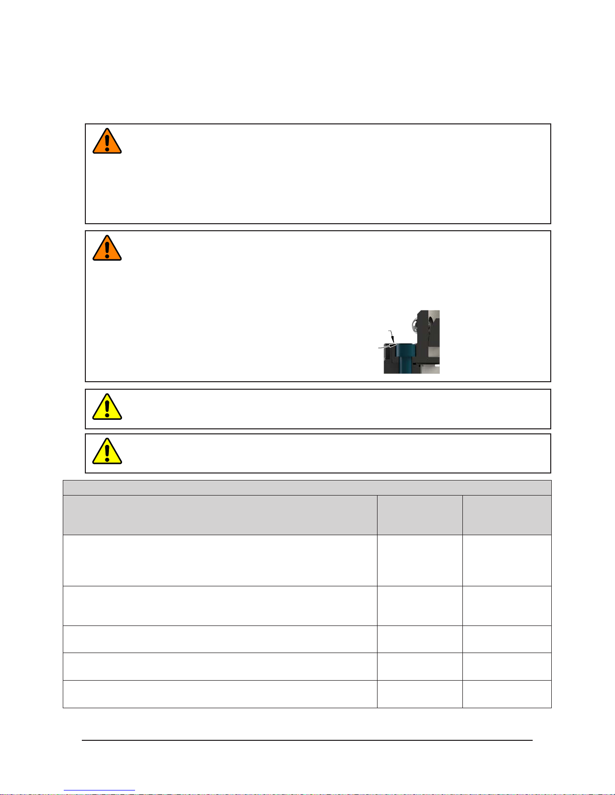
DANGER:ThegapbetweentheMasterandToolsidesisapinchpoint.Allpersonnel
shouldbepreventedfromplacinganypartoftheirbodyorclothinginthegap,
especiallyduringactuationofthelockingmechanism.
The customer is responsible for understanding the function of the Tool Changer and implementing the
proper fasteners and/or software to operate the Tool Changer safely. The Tool Changer should be controlled
such that there is no chance of locking or unlocking in a position that would endanger personnel and/or
equipment. If the Tool Changer is specied with Lock/Unlock (L/U) and Ready-to-Lock (RTL) sensing
capability, the status should be monitored and proper interlocks applied to prevent injury to personnel and
equipment.
Pinnacle Park • 1031 Goodworth Drive • Apex, NC 27539 • Tel: 919.772.0115 • Fax: 919.772.8259 • www.ati-ia.com • Email: info@ati-ia.com
A-6
Page 8
Quick Change Installation and Operation Manual
Document #9620-20-A-General TOC and Introduction-08
All pneumatic and uid components (i.e. ttings, tubing) must be capable of withstanding the repetitive
motions of the application without failing. The routing of electrical, uid, and pneumatic lines must
minimize the possibility of stress/strain, kinking, rupture, etc. Failure of critical electrical, uid, or
pneumatic lines to function properly may result in injury to personnel and equipment.
All electrical power, pneumatic and uid circuits should be disconnected during servicing.
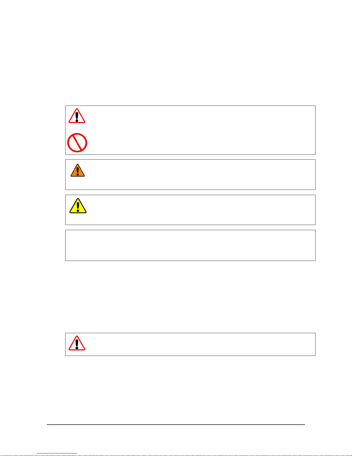
2.3 Safety Precautions
WARNING: Removealltemporaryprotectivematerials(caps,plugs,tape,etc.)on
lockingfaceofToolChangerandmodulespriortooperation.Failuretodosowillresult
indamagetoToolChangers,modules,andend-of-armtoolingandcouldcauseinjury
to personnel.
WARNING: DonotperformmaintenanceorrepaironToolChangerormodulesunless
theToolissafelysupportedordockedinthetoolstand,allenergizedcircuits(e.g.
electrical,air,water,etc.)areturnedoff,pressurizedconnectionspurgedandpower
dischargedfromcircuitsinaccordancewiththecustomer’ssafetypracticesand
policies.InjuryorequipmentdamagecanoccurwithToolnotdockedandenergized
circuitson.DocktheToolsafelyinthetoolstand,turnoffanddischargeallenergized
circuits,purgeallpressurizedconnections,verifyallenergizedcircuitsarede-energized
beforeperformingmaintenanceorrepaironToolChangerormodules.
WARNING: Duringoperation,theareabetweentheMasterandToolmustbekept
clear.FailuretokeepareaclearwillresultindamagetoToolChanger,modules,orendof-armtoolingandcouldcauseinjurytopersonnel.
WARNING: TheToolChangerisonlytobeusedforintendedapplicationsand
applicationsapprovedbythemanufacturer.UsingtheToolChangerinapplications
otherthanintendedwillresultindamagetoToolChanger,modules,orend-of-arm
toolingandcouldcauseinjurytopersonnel.
CAUTION:TheMasterplatelockingmechanismmustnotbeactuatedwithoutbeing
mountedtotherobotinterfaceplate.DamagetotheCoverplateandO-ringmayresult.
AlwaysattachtheMasterplatetotherobotinterfaceplatepriortoattemptingany
operations.
Pinnacle Park • 1031 Goodworth Drive • Apex, NC 27539 • Tel: 919.772.0115 • Fax: 919.772.8259 • www.ati-ia.com • Email: info@ati-ia.com
A-7
Page 9

Quick Change Installation and Operation Manual
Document #9620-20-A-General TOC and Introduction-08
3. Product Overview
3.1 Tool Changers
There are many different types of Tool Changers, Manual, Heavy Automation, Rail, Hollow Wrist, etc,
which are specically suited for the application they are designed for. A Tool Changer enhances the
exibility and reliability of a robotic cell. Robotic Tool Changers are used in automated Tool change
applications as well as manual Tool change operations. Robotic Tool Changers also provide a method for
quick Tool change for maintenance purposes.
Automatic Tool Changers provide added exibility to robot applications by allowing one robot to change
end-effectors, such as grippers and vacuum tooling. The Quick-Change products are pneumatically or
electrically operated devices consisting of a Master Plate and Tool Plate using a patented stainless steel
locking mechanism. Add-on utility modules provide electrical pass-through of, DeviceNet™, Ethernet,
PROFINET™ or PROFIBUS™ bus network signals, high current and servo signals, as well as air, vacuum,
and uid pass-through.
Tool Changers can be equipped with sensors to detect when the Tool Changer is in the locked/unlocked
positions and if the Tool plate is present. Some models require an optional Sensor Interface Plate (SIP) plate
to mount the lock and unlock sensors. If required, the use of a SIP is highly recommended for achieving the
highest level of safety and reliability.
The ATI Tool Changer has been designed to provide extremely long life with little maintenance.
3.1.1 Manually Actuated
ATI’s Manual Tool Changers provide a cost effective solution for quickly changing tools by hand.
They feature a unique design that combines high strength, excellent repeatability and a lever or
screw-cam locking mechanism with multiple fail-safe features, which resists vibration and prevents
loosening. The Manual Tool Changers also feature quick-action locking for manual operation.
These robust and compact Manual Tool Changers can handle payloads up to 80 pounds (36 kg) as
well as pass pneumatics and electrical signals.
3.1.2 Quick-Change (Round Body style)
The Quick-Change robotic Tool Changer has been designed to incorporate high strength in a small,
low-weight package. The Tool change system consists of two primary parts: the Master plate and
the Tool plate. The Master plate is mounted to a robot while the customer supplied end-effector
is typically attached to the Tool plate. The Master plate is typically mounted to the robot with an
optional interface plate. Many models have integrated pass-through air ports.
3.1.3 Heavy Automation
The Heavy Automation Robotic Tool Changer line has been developed for resistance welding and
medium-duty to heavy-duty material handling. Because a Tool Changer uses specic modules
to pass utilities such as uids, electrical, and pneumatics, it can be custom congured to handle
numerous applications.
3.2 Utility Couplers
The Utility Coupler from ATI was developed for heavy-duty, automated industrial applications where there
is a need to change tools that pass utilities such as air and electrical signals. Unlike other traditional manual
methods of connecting multiple lines, the ATI Utility Coupler is especially congured for coupling lines and
restoring operations more quickly. The modular body design is capable of mounting any of ATI’s standard
add-on utility modules and is designed to improve cycle time as well as add exibility to any production
cell. The Master-side connection can feature an unique compliance mechanism that allows for large tooling
misalignments. The Utility Coupler can be provided with an ATI locking mechanism or a drive cylinder.
Pinnacle Park • 1031 Goodworth Drive • Apex, NC 27539 • Tel: 919.772.0115 • Fax: 919.772.8259 • www.ati-ia.com • Email: info@ati-ia.com
A-8
Page 10

Quick Change Installation and Operation Manual
Document #9620-20-A-General TOC and Introduction-08
4. Terms and Conditions of Sale
The following Terms and Conditions are a supplement to and include a portion of ATI’s Standard Terms and
Conditions, which are on le at ATI and available upon request.
ATI warrants to Purchaser that robotic Tool Changer products purchased hereunder will be free from defects
in material and workmanship under normal use for a period of three (3) years from the date of shipment. This
warranty does not cover components subject to wear and tear under normal usage or those requiring periodic
replacement. ATI will have no liability under this warranty unless: (a) ATI is given written notice of the claimed
defect and a description thereof within thirty (30) days after Purchaser discovers the defect and in any event not
later than the last day of the warranty period; and (b) the defective item is received by ATI not later ten (10) days
after the last day of the warranty period. ATI’s entire liability and Purchaser’s sole remedy under this warranty is
limited to repair or replacement, at ATI’s election, of the defective part or item or, at ATI’s election, refund of the
price paid for the item. The foregoing warranty does not apply to any defect or failure resulting from improper
installation, operation, maintenance or repair by anyone other than ATI.
ATI will in no event be liable for incidental, consequential or special damages of any kind, even if ATI has been
advised of the possibility of such damages. ATI’s aggregate liability will in no event exceed the amount paid by
purchaser for the item which is the subject of claim or dispute. ATI will have no liability of any kind for failure of
any equipment or other items not supplied by ATI.
No action against ATI, regardless of form, arising out of or in any way connected with products or services supplied
hereunder may be brought more than one (1) year after the cause of action accrued.
No representation or agreement varying or extending the warranty and limitation of remedy provisions contained
herein is authorized by ATI, and may not be relied upon as having been authorized by ATI, unless in writing and
signed by an executive ofcer of ATI.
Unless otherwise agreed in writing by ATI, all designs, drawings, data, inventions, software and other technology
made or developed by ATI in the course of providing products and services hereunder, and all rights therein under
any patent, copyright or other law protecting intellectual property, shall be and remain ATI’s property. The sale of
products or services hereunder does not convey any express or implied license under any patent, copyright or other
intellectual property right owned or controlled by ATI, whether relating to the products sold or any other matter
except for the license expressly granted below.
In the course of supplying products and services hereunder, ATI may provide or disclose to Purchaser condential
and proprietary information of ATI relating to the design, operation or other aspects of ATI’s products. As between
ATI and Purchaser, ownership of such information, including without limitation any computer software provided
to Purchaser by ATI, shall remain in ATI and such information is licensed to Purchaser only for Purchaser’s use in
operating the products supplied by ATI hereunder in Purchaser’s internal business operations.
Without ATI’s prior written permission, Purchaser will not use such information for any other purpose or provide or
otherwise make such information available to any third party. Purchaser agrees to take all reasonable precautions to
prevent any unauthorized use or disclosure of such information.
Purchaser will not be liable hereunder with respect to disclosure or use of information which: (a) is in the public
domain when received from ATI; (b) is thereafter published or otherwise enters the public domain through no fault
of Purchaser; (c) is in Purchaser’s possession prior to receipt from ATI; (d) is lawfully obtained by Purchaser from a
third party entitled to disclose it; or (f) is required to be disclosed by judicial order or other governmental authority,
provided that, with respect to such required disclosures, Purchaser gives ATI prior notice thereof and uses all legally
available means to maintain the condentiality of such information.
Pinnacle Park • 1031 Goodworth Drive • Apex, NC 27539 • Tel: 919.772.0115 • Fax: 919.772.8259 • www.ati-ia.com • Email: info@ati-ia.com
A-9
Page 11

Manual, Robotic Tool Changer, QC-210
Document #9620-20-B-210 Series Base Tool Changer-26
Table of Contents
B. Base Tool Changer ..................................................................................................................B-3
QC-210 Series—Robotic Tool Changer
......................................................................................B-3
1. Product Overview ..................................................................................................................B-3
1.1 Master Plate Assembly ............................................................................................................. B-4
1.2 T ool Plate Assembly .................................................................................................................. B-5
1.3 Optional Modules ......................................................................................................................B-5
2. Installation .............................................................................................................................B-6
2.1 Master Interface .........................................................................................................................B-7
2.2 Master Plate Installation ...........................................................................................................B-8
2.3 Master Plate Removal ...............................................................................................................B-8
2.4 Tool Interface .............................................................................................................................B-9
2.5 Tool Plate Installation (includes Bolt-Down Plate) ...............................................................B-10
2.6 Tool Plate Removal (includes Bolt-Down Plate) ....................................................................B-11
2.7 Pneumatic Requirements .......................................................................................................B-12
2.7.1 Valve Requirements for Air Adapter Modules ................................................................B-12
2.8 Electrical Connections ............................................................................................................B-13
2.8.1 PNP Type Lock, Unlock and RTL Sensors (-SM, -SR, -SL, -ST sensor designations) .B-13
2.8.2 NPN Type Lock, Unlock and RTL Sensors (-SP, -SE, -SU sensor designations) ..........B-13
3. Operation .............................................................................................................................B-14
3.1 Conditions for Coupling .........................................................................................................B-15
3.2 Fail-Safe Operation .................................................................................................................B-16
3.3 Conditions for Uncoupling .....................................................................................................B-17
3.4 ToolIdentication ....................................................................................................................B-17
3.5 Tool Storage Considerations .................................................................................................B-18
4. Maintenance .........................................................................................................................B-19
4.1 Preventive Maintenance .........................................................................................................B-19
4.2 Cleaning and Lubrication of the Locking Mechanism and Alignment Pins ....................... B-20
4.3 Pin Block Inspection and Cleaning .......................................................................................B-22
5. Troubleshooting and Service Procedures ........................................................................B-23
5.1 Troubleshooting Procedures .................................................................................................B-23
5.2 Service Procedures .................................................................................................................B-24
5.2.1 Sensor Replacement Procedures .................................................................................B-24
5.2.2 V-ring Seal Replacement ...............................................................................................B-34
5.2.3 Alignment Pin Replacement ..........................................................................................B-35
Pinnacle Park • 1031 Goodworth Drive • Apex, NC 27539 • Tel: 919.772.0115 • Fax: 919.772.8259 • www.ati-ia.com • Email: info@ati-ia.com
B-1
Page 12

Manual, Robotic Tool Changer, QC-210
Document #9620-20-B-210 Series Base Tool Changer-26
6. Serviceable Parts ................................................................................................................B-36
6.1 Models 9121-210xM-0-0-0-0-S0 ..............................................................................................B-36
6.2 Models 9121-210xM-0-0-0-0-SL and 9121-210xM-0-0-0-0-SE ...............................................B-37
6.3 Models 9121-210xM-0-0-0-0-SM, 9121-210xM-0-0-0-0-SP and 9121-210xM-0-0-0-0-SR .....B-38
6.4 Models 9121-210xM-0-0-0-0-ST and 9121-210xM-0-0-0-0-SU ...............................................B-39
6.5 Standard Tool Plate ................................................................................................................B-40
6.6 Bolt-Down Tool Plate .............................................................................................................B-41
7. Specications ......................................................................................................................B-42
8. Drawings ..............................................................................................................................B-43
8.1 QC-210 Tool Changer ..............................................................................................................B-43
8.2 Bolt-Down Tool Plate .............................................................................................................B-46
Pinnacle Park • 1031 Goodworth Drive • Apex, NC 27539 • Tel: 919.772.0115 • Fax: 919.772.8259 • www.ati-ia.com • Email: info@ati-ia.com
B-3
Page 13

Manual, Robotic Tool Changer, QC-210
Document #9620-20-B-210 Series Base Tool Changer-26
B. Base Tool Changer
QC-210 Series—Robotic Tool Changer
1. Product Overview
The Tool Changer provides exibility to robot applications by that allow the robot to change customer tooling (e.g.,
grippers, vacuum cup tooling, pneumatic and electric motors, weld guns, etc.) automatically. The Tool Changer
consists of a Master plate and a Tool plate. The Master plate is attached to a robot, while end-effectors such as
grippers, material handlers, etc. are attached to one or more Tool plates.
The Master plate locks to the Tool plate with a pneumatically driven locking mechanism. This locking mechanism
uses a patented, multi-tapered cam with ball locking technology and a patented fail-safe mechanism.
The robot can be programmed to select the desired customer tooling by coupling the Master plate to the Tool plate
attached to the tooling. Electrical signals, pneumatic power, and uids can be transferred to the customer tooling
through the Master plate and Tool plate by optional modules. See the respective manuals for these options for more
details.
For the most current product information and specications on the QC-210 Series of Tool Changers, please click
the following link: http://www.ati-ia.com/products/toolchanger/QC.aspx?ID=QC-210
Pinnacle Park • 1031 Goodworth Drive • Apex, NC 27539 • Tel: 919.772.0115 • Fax: 919.772.8259 • www.ati-ia.com • Email: info@ati-ia.com
B-3
Page 14
Manual, Robotic Tool Changer, QC-210
Document #9620-20-B-210 Series Base Tool Changer-26
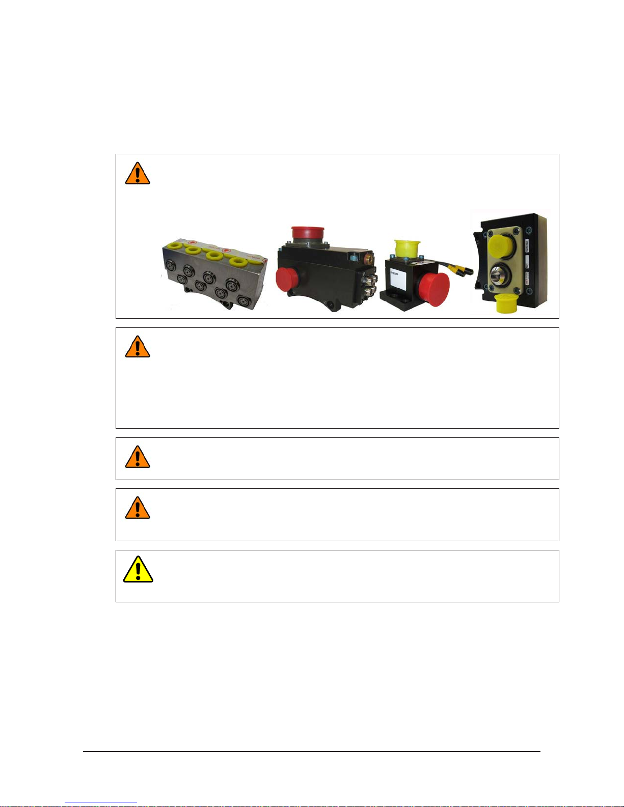
1.1 Master Plate Assembly
The Master plate assembly includes the following features:
• An anodized aluminum body.
• A hardened stainless steel locking mechanism (a cam, male coupling, and chrome steel ball bearings).
• Hardened steel alignment pins that mate with bushings on the Tool plate.
• (4) ats for mounting optional modules. Flat an is dedicated for mounting an air adapter or a valve
adapter and control/signal module combination. Flats B, C, and D are for optional modules.
• Proximity sensor assemblies used to verify the lock/unlock position of the piston and cam.
• Proximity sensors used to verify Tool plate presence when coupled.
• A mounting pattern for a robot arm or an interface plate.
• Routing channels for the RTL, Lock, and Unlock sensor cables.
Extreme pressure grease is applied to the cam, male coupling, ball bearings, and pins to enhance
performance and maximize the life of the Master plate.
Figure 1.1—Master Plate Assembly
RTL (R1) Proximity Sensor
Assembly
Lock/Unlock Air supplied
through Air/Valve Adapter
mounted to Flat A
(12) Ball Bearing
Male Coupling
(2) Alignment pin
Cam
RTL (R2) Proximity Sensor
Cable Retaining Tab
Common Ledge
Feature for Module
mounted to Flat B, C,
and D
Internal Proximity Sensors
(Lock/Unlock) [Not Visible]
Assembly
Pinnacle Park • 1031 Goodworth Drive • Apex, NC 27539 • Tel: 919.772.0115 • Fax: 919.772.8259 • www.ati-ia.com • Email: info@ati-ia.com
B-4
Page 15
Manual, Robotic Tool Changer, QC-210
Document #9620-20-B-210 Series Base Tool Changer-26
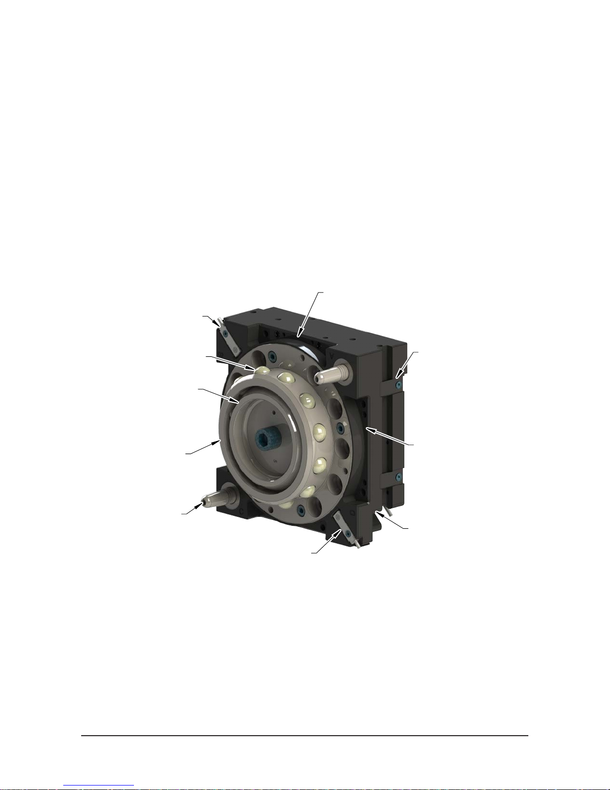
1.2 T ool Plate Assembly
The Tool plate assembly includes the following features:
• An anodized aluminum body.
• A hardened stainless steel bearing race.
• Alignment bushings that mate with pins on the Master plate.
• (4) ats for mounting optional modules. Flat A requires a tool adapter assembly that is compatible with
the air or valve adapter used on the Master Plate. Flats B, C, and D are for optional modules.
• Ferrous metal proximity sensor targets.
• A mounting pattern for customer tooling or a tooling interface plate.
Figure 1.2—T ool Plate Assembly
Common Ledge Feature for
Module mounted to Flat A,
B, C, and D
(2) Alignment Pin
Bushing
Bearing Race
Proximity Sensor
Assembly Target (RTL)
Proximity Sensor
Assembly Target (RTL)
1.3 Optional Modules
The optional modules are mounted to the Master and Tool plate using a common ledge mounting feature and
pass utilities to customer tooling.
For assistance in the choosing the right modules for your particular application, visit our website (http://
www.ati-ia.com/products/toolchanger/QC.aspx?ID=QC-210) to see what is available or contact an ATI sales
representative.
Pinnacle Park • 1031 Goodworth Drive • Apex, NC 27539 • Tel: 919.772.0115 • Fax: 919.772.8259 • www.ati-ia.com • Email: info@ati-ia.com
B-5
Page 16
Manual, Robotic Tool Changer, QC-210
Document #9620-20-B-210 Series Base Tool Changer-26
2. Installation
All fasteners used to mount the Tool Changer to the robot and to customer’s tooling should be tightened to a
torque value as indicated. Refer to Table 2.1. Furthermore, removable (blue) Loctite 242 must be used on these
fasteners. Table 2.1 contains recommended values based on the engineering standards.
WARNING: Do not perform maintenance or repair(s) on the Tool Changer or modules unless
the Tool is safely supported or placed in the tool stand, all energized circuits (e.g. electrical,
air, water, etc.) are turned off, pressurized connections are purged and power is discharged
from the circuits in accordance with the customer’s safety practices and policies. Injury or
equipment damage can occur with the Tool not placed and energized circuits on. Place the
Tool in the tool stand, turn off and discharge all energized circuits, purge all pressurized
connections, and verify all circuits are de-energized before performing maintenance or
repair(s) on the Tool Changer or modules.
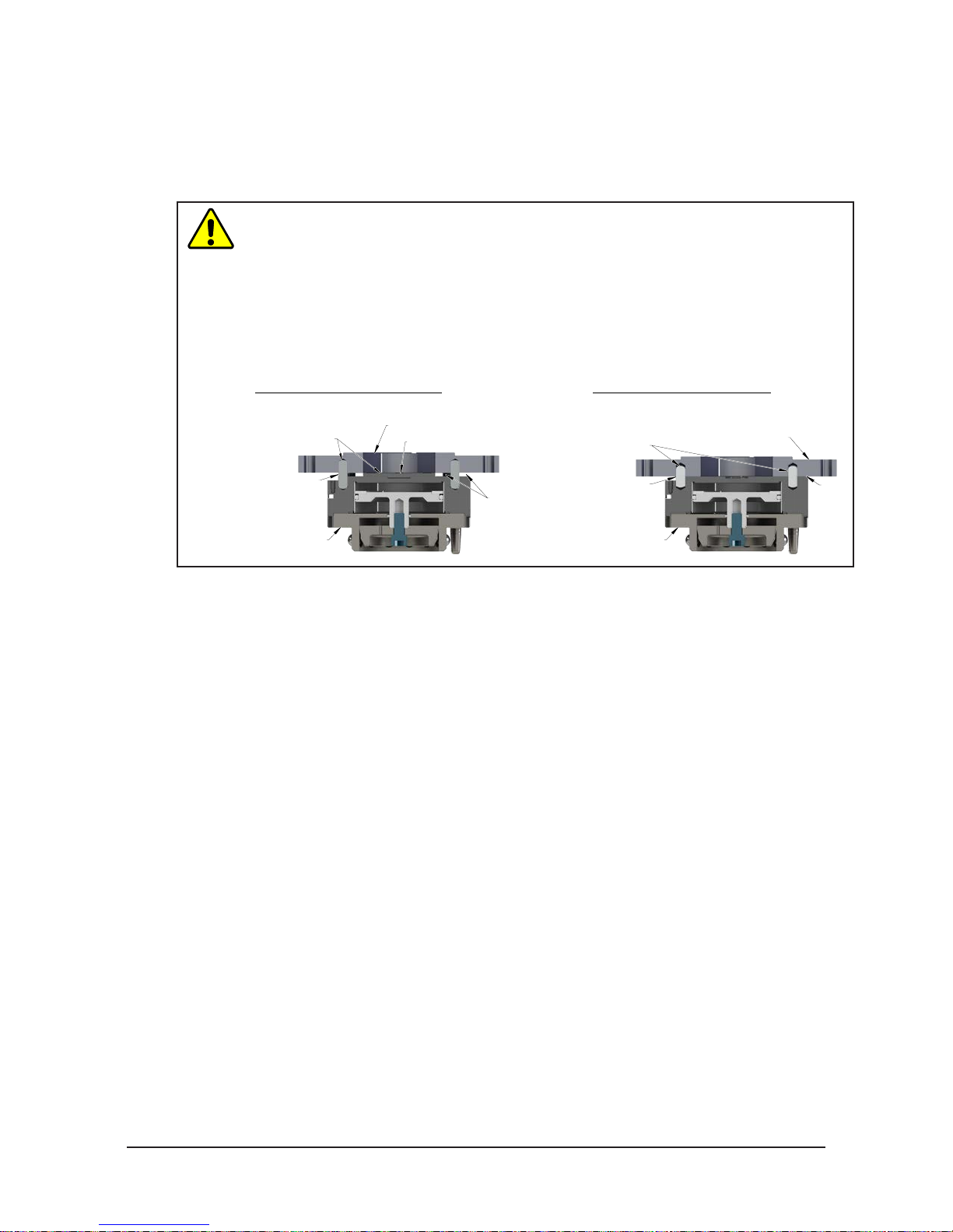
WARNING: Do not use lock washers under the head of the mounting fasteners or allow the
mounting fasteners to protrude above the mating surfaces of the Master and Tool plates. That
allow fasteners to protrude above the mating surface will create a gap between the Master
and Tool plates and not allow the locking mechanism to fully engage, this can cause damage
to equipment or personal injury. The mounting fasteners must be ush or below the mating
surfaces of the Master and Tool plates.
Mating Surface
Head of Mounting Fastener Must Be Flush or
Below Mating Surface. (Do Not Use Lock
Washer under Head of Mounting Fastener.)
CAUTION: Do not use fasteners with pre-applied adhesive more than once. Fasteners might
become loose and cause equipment damage. Always apply new thread locker when reusing
fasteners.
CAUTION: Do not use fasteners that exceed the thread depth in the Tool Changer. Refer to
Section 8—Drawings for details on the mounting hole thread depth. Secure the Tool Changer
with the proper length fasteners. This is true for both robot and tool interfaces.
Table 2.1—FastenerSize,Class,andTorqueSpecications
Mounting Conditions
Master plate to Interface plate and
Interface plate to Robot (6061-T6 aluminum)
Minimum thread engagement of 0.59” (15 mm) [1.5X fastener Ø].
Conrm available engagement with Robot Manufacturer
Interface plate to Robot (steel; USS ≥ 90KSI)
Minimum thread engagement of 0.39” (10 mm) [1.0X fastener Ø].
Conrm available engagement with Robot Manufacturer
Tool plate (aluminum) to Tool interface plate (aluminum)
Minimum thread engagement of 0.47” (12 mm) [1.5X fastener Ø].
Tool interface plate (aluminum) to Tool plate (aluminum)
Minimum thread engagement of 0.59” (15 mm) [1.5X fastener Ø].
Tool interface plate (aluminum) to Tool plate (aluminum)
Minimum thread engagement of 0.71” (18 mm) [1.5X fastener Ø].
Fastener Size
and Property
Class
M10-1.5
Class 12.9
M10-1.5
Class 12.9
M8-1.25
Class 12.9
M10-1.5
Class 12.9
M12-1.75
Class 12.9
Recommended
Torque
38 ft-lbs
(52 Nm)
55 ft-lbs
(75 Nm)
20 ft-lbs
(27 Nm)
38 ft-lbs
(52 Nm)
70 ft-lbs
(94 Nm)
Pinnacle Park • 1031 Goodworth Drive • Apex, NC 27539 • Tel: 919.772.0115 • Fax: 919.772.8259 • www.ati-ia.com • Email: info@ati-ia.com
B-6
Page 17
Manual, Robotic Tool Changer, QC-210
A boss and two dowel pins can
Document #9620-20-B-210 Series Base Tool Changer-26
2.1 Master Interface
The Master plate is typically attached to the robot arm. An interface plate can adapt the Master plate to a
specic robot arm. Alignment features (dowel holes and bosses) accurately position and bolt holes secure
the Master plate to the robot arm or an interface plate. Custom interface plates are available from ATI upon
request. (Refer to the Drawing Section for technical information on the mounting features.)
CAUTION: Do not use more than two alignment features when that secure a Master
plate to an interface plate. Using more than two alignment features can cause damage
to equipment. Use either two dowel pins or a single dowel pin along with a boss/recess
feature to align the Master plate with the interface plate.
CAUTION: Do not use dowel pins that are too long or do not allow the interface plate
and Master body to mate ush. Using dowel pins that are too long will cause a gap
between the interface plate and Master body and damage to the equipment. Use dowel
pins that will not extend further than allowed by the Master body.
Incorrect Mounting of Master Plate
be difficult to align and can
cause damage to equipment.
Interface Plate
Optional Boss
Correct Mounting of Master Plate
(or a single dowel
used as alignment features.
Two dowel pins
with a boss/recess)
pin along
Interface Plate
Dowel pins that are
too long can cause a
gap between interface
plate and Master Plate.
Master Plate
GapGap
Correct size dowel
pins allow the interface
plate and Master
plate to mount flush.
Master Plate
Flush
If the customer chooses to design and build an interface plate, consider the following points:
• The interface plate should include bolt holes for mounting and either two dowel pins or a dowel pin
and a boss for accurate positioning on the robot and Master plate. The dowel and boss features prevent
unwanted rotation. Refer to the robot manual for robot mounting features.
• The thickness of the interface plate must be sufcient to provide the necessary thread engagement for
the mounting bolts.
• Dowel pins must not extend out from the surface of the interface plate farther than the depth of the
dowel holes in the Master plate.
• If a boss is used on the Master plate, a recess of proper depth and diameter must be machined into the
interface plate to correspond with the boss on the Master plate.
• Mounting bolts that are too long can create a gap between the interface plate and the Master plate,
which can damage equipment.
• The interface plate must provide rigid mounting to the Master plate.
• The interface plate design must account for clearances required for Tool Changer module attachments
and accessories.
Pinnacle Park • 1031 Goodworth Drive • Apex, NC 27539 • Tel: 919.772.0115 • Fax: 919.772.8259 • www.ati-ia.com • Email: info@ati-ia.com
B-7
Page 18
Manual, Robotic Tool Changer, QC-210
Document #9620-20-B-210 Series Base Tool Changer-26
2.2 Master Plate Installation
Tools required: 8 mm Allen® wrench (hex key), torque wrench
Supplies required: Clean rag, Loctite® 242
1. Clean the mounting surfaces.
2. If required, install the interface plate to the robot arm, align using the boss or dowel pins and secure with
customer supplied fasteners.
3. Align the dowel pins to the corresponding holes in the Master plate and secure the Master plate to the
robot arm or interface plate with customer supplied (10) M10-1.5 socket head cap screws using an 8 mm
Allen wrench. Refer to Section 8—Drawings for mounting pattern. Apply Loctite 242 to threads (see
Table 2.1 for proper fasteners and torque).
NOTICE: If an ATI interface plate is used, fasteners to mount the Master plate is supplied with
the interface plate.
4. Connect utilities to the appropriate module and Master plate connections. For pneumatic lock and unlock
connection refer to Section 2.7—Pneumatic Requirements.
5. After the procedure is complete, resume normal operation.
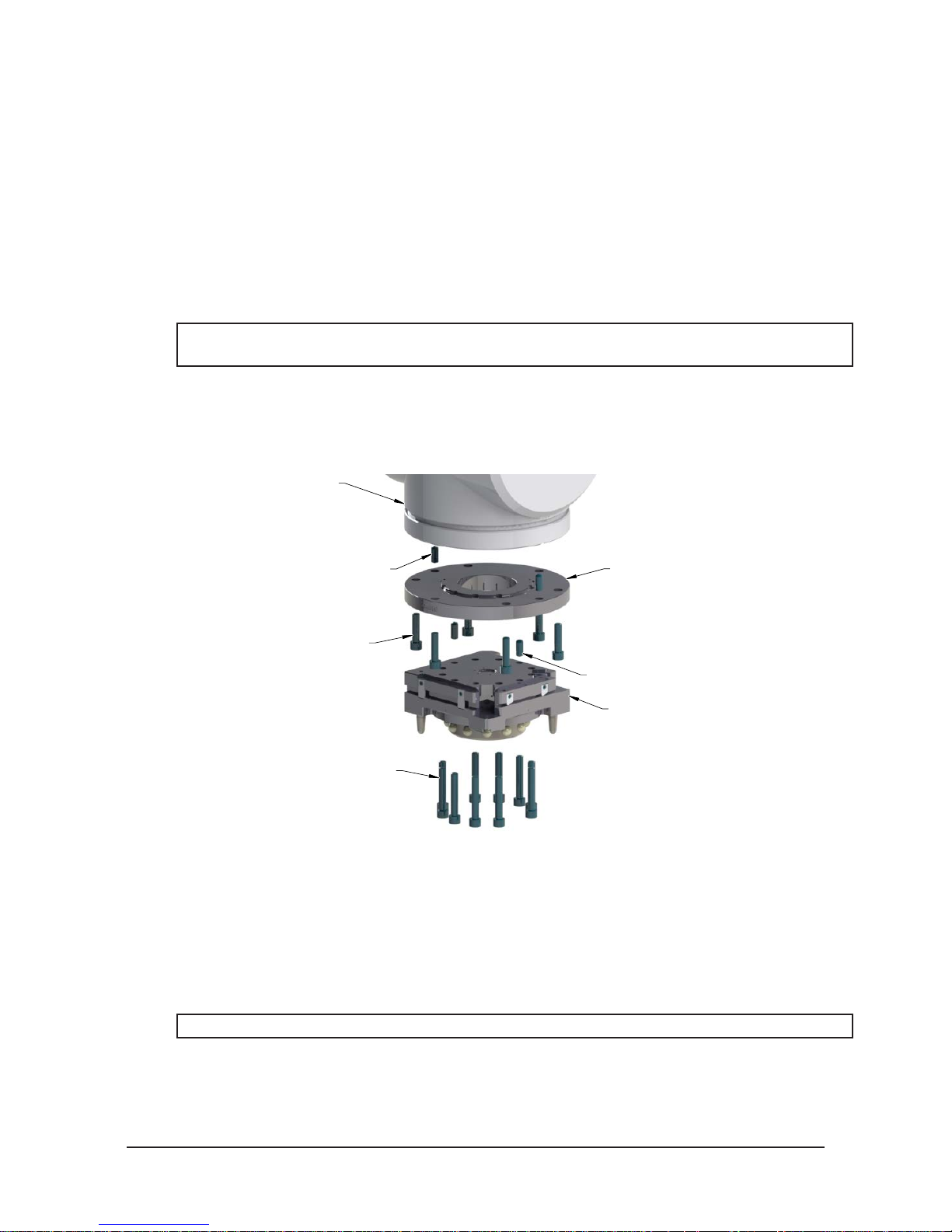
Figure 2.1—Typical Master Plate Installation
Robot Arm
Dowel Pin (Customer Supplied)
Socket Head Cap Screw
(Customer Supplied)
(10) M10-1.5 Socket Head Cap Screw
(Refer to Table 2.1)
(Customer Supplied)
2.3 Master Plate Removal
Tools required: 8 mm Allen wrench (hex key)
1. Place the Tool in a secure location.
2. Uncouple the Master and Tool plates.
3. Turn off and de-energize all energized circuits (e.g. electrical, air, water, etc.).
4. Disconnect all utilities (e.g. electrical, air, water, etc.).
Robot Interface Plate
(Customer Supplied)
(If required, custom RIP’s
are available from ATI.)
Dowel Pin (Customer Supplied)
Master Plate
NOTICE: Support the Master plate while removing the fasteners.
5. Remove the (10) M10 socket head cap screws connecting the Master plate to the robot arm or interface
plate using an 8 mm Allen wrench.
Pinnacle Park • 1031 Goodworth Drive • Apex, NC 27539 • Tel: 919.772.0115 • Fax: 919.772.8259 • www.ati-ia.com • Email: info@ati-ia.com
B-8
Page 19
Manual, Robotic Tool Changer, QC-210
Correct Mounting of Tool Plate
Interface Plate
Incorrect Mounting of Tool Plate
Document #9620-20-B-210 Series Base Tool Changer-26
2.4 Tool Interface
The Tool plate is attached to the customer’s tooling. An interface plate can adapt the Tool plate to customer
tooling. Alignment features (dowel holes and a recess) accurately position and bolt holes secure the Tool
plate to customer tooling. Custom interface plates can be supplied by ATI (Refer to the application drawing).
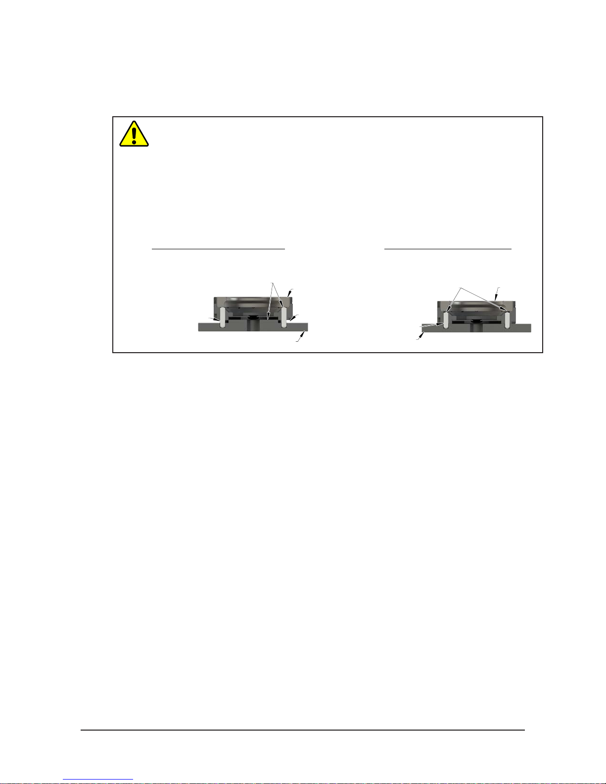
CAUTION: Do not use more than two alignment features when that secure a Tool plate
to an interface plate. Using more than two alignment features can cause damage to
equipment. Use either two dowel pins or a single dowel pin along with a boss/recess
feature to align the Tool plate with the interface plate.
CAUTION: Do not use dowel pins that are too long or do not allow the interface plate
and Tool body to mate ush. Using dowel pins that are too long will cause a gap
between the interface plate and Tool body and damage to the equipment. Use dowel
pins that will not extend further than allowed by the Tool body.
Boss and two dowel pins
as alignment features can be
difficult to align and can
damage equipment.
Dowel pins
are too long and
cause a gap between
interface plate and Tool.
Tool Plate
Gap
single dowel pin along with a
proper size allowing
interface plate and Tool
Plate to mount flush.
Two dowel pins (or a
boss/recess) used as
alignment features.
Dowel pins are
Interface Plate
Tool Plate
If the customer chooses to design and build a tool interface plate, consider the following points:
• The interface plate should include bolt holes for mounting and either two dowel pins or a dowel
pin and a boss for accurate positioning on the customer tooling and Tool plate. The dowel and boss
features prevent unwanted rotation.
• Dowel pins must not extend out from the surface of the interface plate farther than the depth of the
dowel holes in the Tool plate.
• The thickness of the interface plate must be sufcient to provide the necessary thread engagement for
the mounting bolts. Fasteners should meet minimum recommended engagement lengths while not
exceeding the maximum available thread depth. Use of bolts that are too long can cause damage to the
tool side changer.
• The plate design must account for clearances required for Tool Changer module attachments and
accessories.
• If a boss is to be used on the interface plate, a boss of proper height and diameter must be machined
into the interface plate to correspond with the recess in the Tool plate.
• The interface plate must have a hole in its center for manually returning the locking mechanism to
the unlocked position under adverse conditions (i.e. unintended loss of power and/or air pressure).
The center access hole with a minimum diameter of the 1” (25.4 mm) prevents debris from the
contaminating the locking mechanism. Greater protection is provided by leaving the race cover and
grommet in place.
Pinnacle Park • 1031 Goodworth Drive • Apex, NC 27539 • Tel: 919.772.0115 • Fax: 919.772.8259 • www.ati-ia.com • Email: info@ati-ia.com
B-9
Page 20
Manual, Robotic Tool Changer, QC-210
Document #9620-20-B-210 Series Base Tool Changer-26
2.5 Tool Plate Installation (includes Bolt-Down Plate)
Tools required: 8 mm, 10 mm, or 12 mm Allen wrench (hex key), torque wrench
Supplies required: Clean rag, Loctite 242
1. Clean the mounting surfaces.
2. If required, install the tool interface plate to the customer tooling, align using the boss or dowel pins and
secure with customer supplied fasteners.
3. Align the dowel pins to the corresponding holes in the Tool plate and secure the Tool plate to the tool
interface plate or customer tooling with customer supplied fasteners. Refer to Section 8—Drawings for
mounting pattern. Apply Loctite 242 to threads (see Table 2.1).
NOTICE: If an ATI interface plate is used, fasteners to mount the Tool plate is supplied with the
interface plate.
4. Connect utilities to the appropriate module and Tool plate connections.
5. After the procedure is complete, resume normal operation.
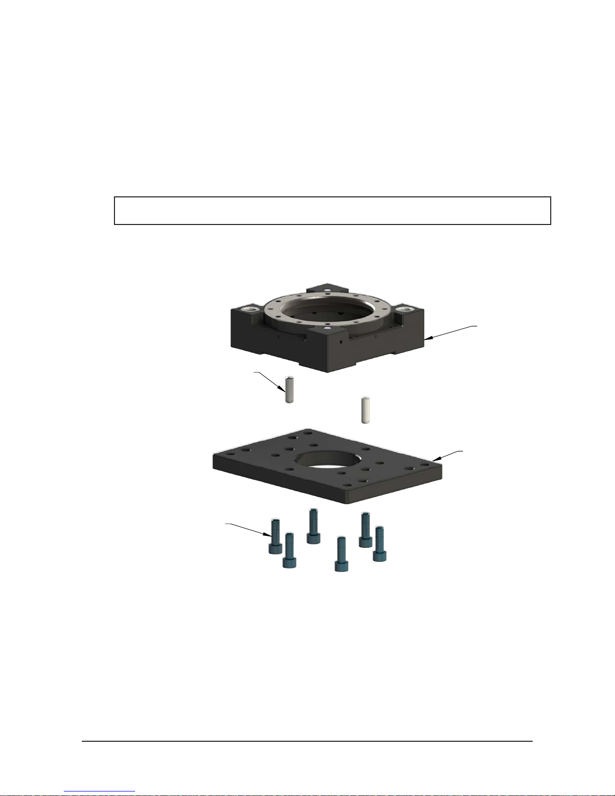
Figure 2.2—Standard Tool Plate Installation (210CT Shown)
Tool Plate
Dowel Pin (Customer Supplied)
(6) M10-1.5 Socket Head Cap Screw
Torque to 52 N-m (38 ft-lbs)
(Customer Supplied)
Tool Interface Plate
(Customer Supplied)
Pinnacle Park • 1031 Goodworth Drive • Apex, NC 27539 • Tel: 919.772.0115 • Fax: 919.772.8259 • www.ati-ia.com • Email: info@ati-ia.com
B-10
Page 21
Manual, Robotic Tool Changer, QC-210
Document #9620-20-B-210 Series Base Tool Changer-26
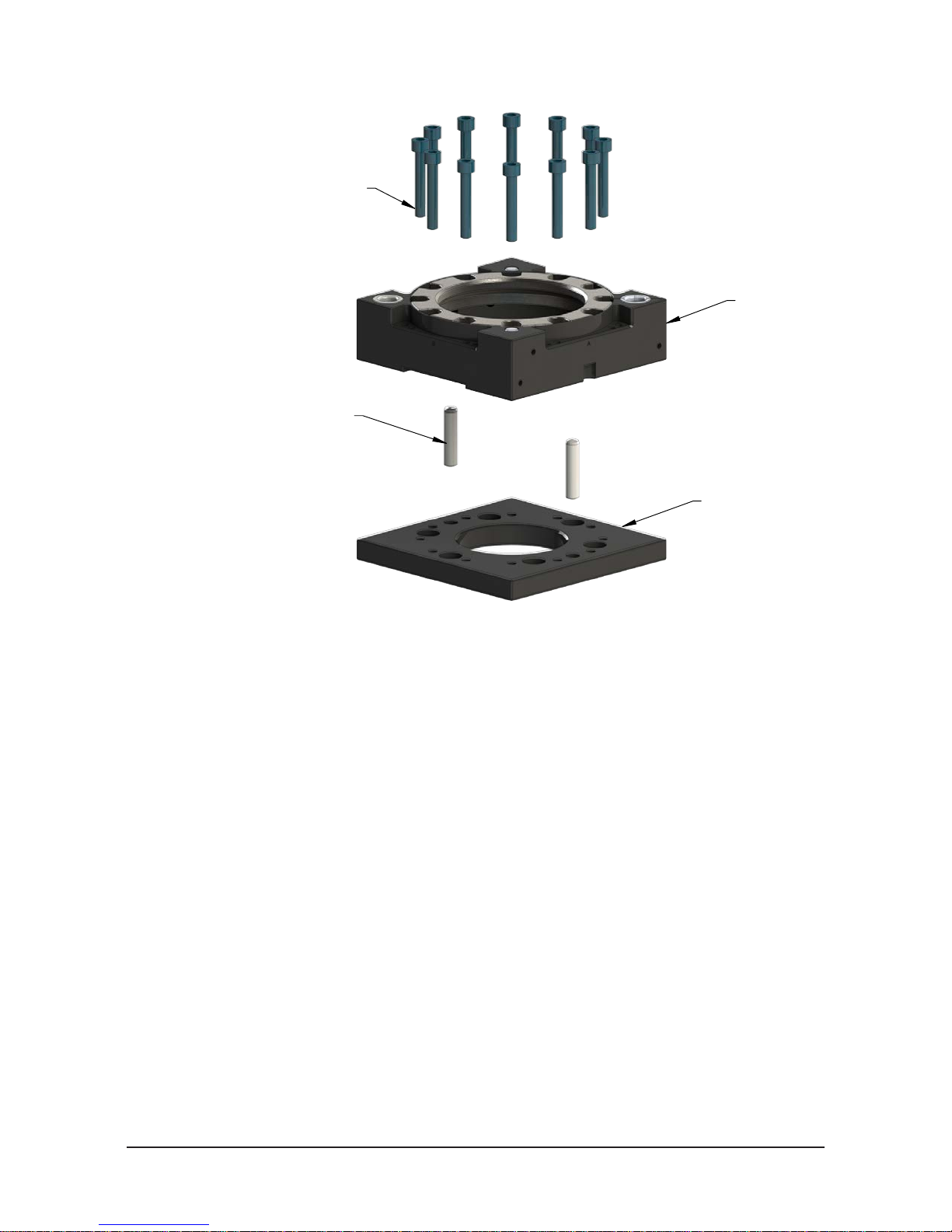
Bolt-Down Tool Plate Installation (210CWT Shown)
(12) M8-1.25 Socket Head Cap Screw
(Refer to Table 2.1)
(Customer Supplied)
Dowel Pin
(Customer Supplied)
Tool Plate
Tool Interface Plate
(Customer Supplied)
2.6 Tool Plate Removal (includes Bolt-Down Plate)
Tools required: 8 mm, 10 mm, or 12 mm Allen wrench (hex key)
1. Place the Tool in a secure location.
2. Uncouple the Master and Tool plates.
3. Turn off and de-energize all energized circuits (e.g. electrical, air, water, etc.).
4. Disconnect all utilities (e.g. electrical, air, water, etc.).
5. Remove the fasteners connecting the Tool plate to the tooling or tool interface plate.
Pinnacle Park • 1031 Goodworth Drive • Apex, NC 27539 • Tel: 919.772.0115 • Fax: 919.772.8259 • www.ati-ia.com • Email: info@ati-ia.com
B-11
Page 22
Manual, Robotic Tool Changer, QC-210
Document #9620-20-B-210 Series Base Tool Changer-26
2.7 Pneumatic Requirements
Proper operation of the locking mechanism requires a constant supply of the clean, dry, non-lubricated air,
with the following conditions:
• Pressure range of the 60 to 100 psi (4.1 - 6.9 bar) Suggested 80 psi.
• Filtered minimum: 40 microns.
To lock or unlock the Tool Changer, a constant supply of the compressed air is required. If there is a loss of
air pressure in the locked state, the cam prole prevents the master plate and tool plate from unlocking, and
the Tool Changer goes into the fail-safe condition.
CAUTION: Do not use the Tool Changer in a fail-safe condition. Damage to the locking
mechanism can occur. Re-establish air pressure and ensure the Tool Changer is in a
secure lock position before returning to normal operations.
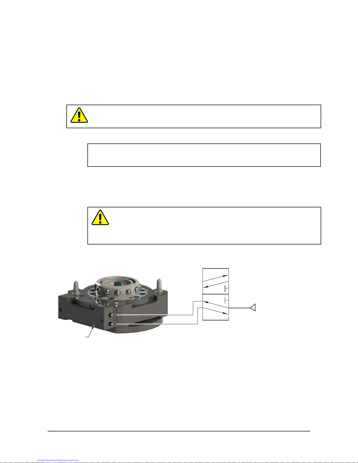
2.7.1 Valve Requirements for Air Adapter Modules
NOTICE: No valve is required when using a valve adapter module. The valve adapter
module has an integrated solenoid valve and only requires the customer to supply a
single air source to the valve adapter.
A customer supplied 2-position 4-way or 5-way valve must be used to actuate the locking
mechanism in the Master plate. It is imperative that when air is supplied to the Lock or Unlock Port
on the Master plate, that the opposite port be vented to atmosphere (i.e., when air is supplied to the
Lock Port, the Unlock Port must be open to the atmosphere.) Failure to vent trapped air or vacuum
on the inactive port may inhibit operation of the valve and prevent coupling or uncoupling.
Air Adapter without
integrated valve
CAUTION: The locking mechanism will not function properly when connected
to a 3-way valve as this type of valve is incapable of venting trapped air or
vacuum from the within the Tool Changer. This could result in damage to the
product, attached tooling, or injury to personnel. Connect the Lock and Unlock
supply air to a 2-position 4-way or 5-way valve.
Figure 2.3—Lock and Unlock Pneumatic Connections
4 or 5-way Valve
Supply Clean, Dry,
Lock Port
Exhaust
Open to Atmosphere
Unlock Port
Non-lubricated Air
60 – 100 psi (4.1 –6.9 Bar)
Pinnacle Park • 1031 Goodworth Drive • Apex, NC 27539 • Tel: 919.772.0115 • Fax: 919.772.8259 • www.ati-ia.com • Email: info@ati-ia.com
B-12
Page 23
Manual, Robotic Tool Changer, QC-210
(3) Blue
Brown (1)
(4) Black
Brown (1)
Black (4)
Blue (3)
+Vs
Output
0 V
NPN
Z
Connector
NPN (Current Sinking)
Document #9620-20-B-210 Series Base Tool Changer-26
2.8 Electrical Connections
The Tool Changer is available with integrated lock/unlock sensors. If the sensors are not used, plugs are
provided to seal the locking mechanism. If a control/signal module is to be utilized on Flat ‘A’ when
ordered, the sensors will be connected to the module prior to shipping.
2.8.1 PNP Type Lock, Unlock and RTL Sensors (-SM, -SR, -SL, -ST sensor
designations)
These sensors are used on the 9121-210AM-0-0-0-0-SM, 9121-210AM-0-0-0-0-SR, 9121-210AM0-0-0-0-SL and 9121-210AM-0-0-0-0-ST.
Table 2.2—PNP (Current Sourcing)
Description Value
Voltage Supply Range 10-30 VDC
Output Circuit PNP make function (NO)
Figure 2.4—PNP Type Lock, Unlock and RTL Sensors
PNP (Current Sourcing)
Brown (1)
Black (4)
PNP
Blue (3)
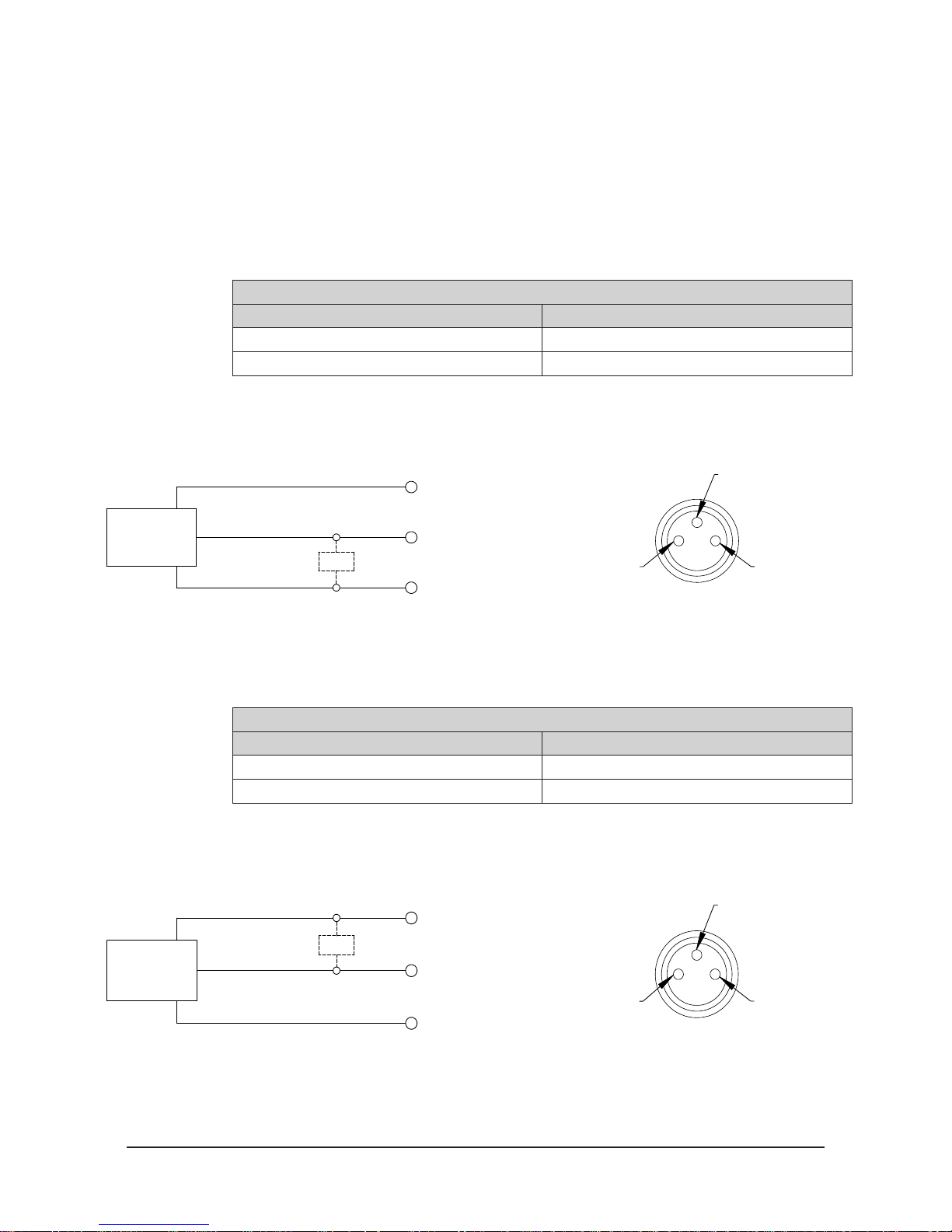
2.8.2 NPN Type Lock, Unlock and RTL Sensors (-SP, -SE, -SU sensor
designations)
These sensors are used on the 9121-210AM-0-0-0-0-SP, 9121-210AM-0-0-0-0-SE, and
9121-210AM-0-0-0-0-SU.
Description Value
Voltage Supply Range 10-30 VDC
Output Circuit NPN make function (NO)
Figure 2.5—NPN Type Lock, Unlock and RTL Sensors
Z
Connector
+Vs
Output
Brown (1)
0 V
Table 2.3—NPN (Current Sinking)
(4) Black
(3) Blue
Pinnacle Park • 1031 Goodworth Drive • Apex, NC 27539 • Tel: 919.772.0115 • Fax: 919.772.8259 • www.ati-ia.com • Email: info@ati-ia.com
B-13
Page 24
Manual, Robotic Tool Changer, QC-210
Document #9620-20-B-210 Series Base Tool Changer-26
3. Operation
The Master plate locking mechanism is pneumatically driven to couple and uncouple with the Tool plate bearing
race.
CAUTION: Operation of the Tool Changer is dependent on the maintaining an air pressure
of 60 to 100 psi (4.1 - 6.9 bar). Damage to the locking mechanism could occur. Robot motion
must be halted If the air supply pressure drops below 60 psi (4.1 bar).
NOTICE: All Tool Changers are lubricated prior to shipment. The customer must apply additional
lubricant to the locking mechanism components and alignment pins prior to operation. Tubes of
lubricant for this purpose are shipped with every Tool Changer. Standard Tool Changers require
MobilGrease XHP222 Special (a NLGI #2 lithium complex grease with molybdenum disulde). For
custom applications, such as food grade or surgical applications, specialized lubricants might be
required.
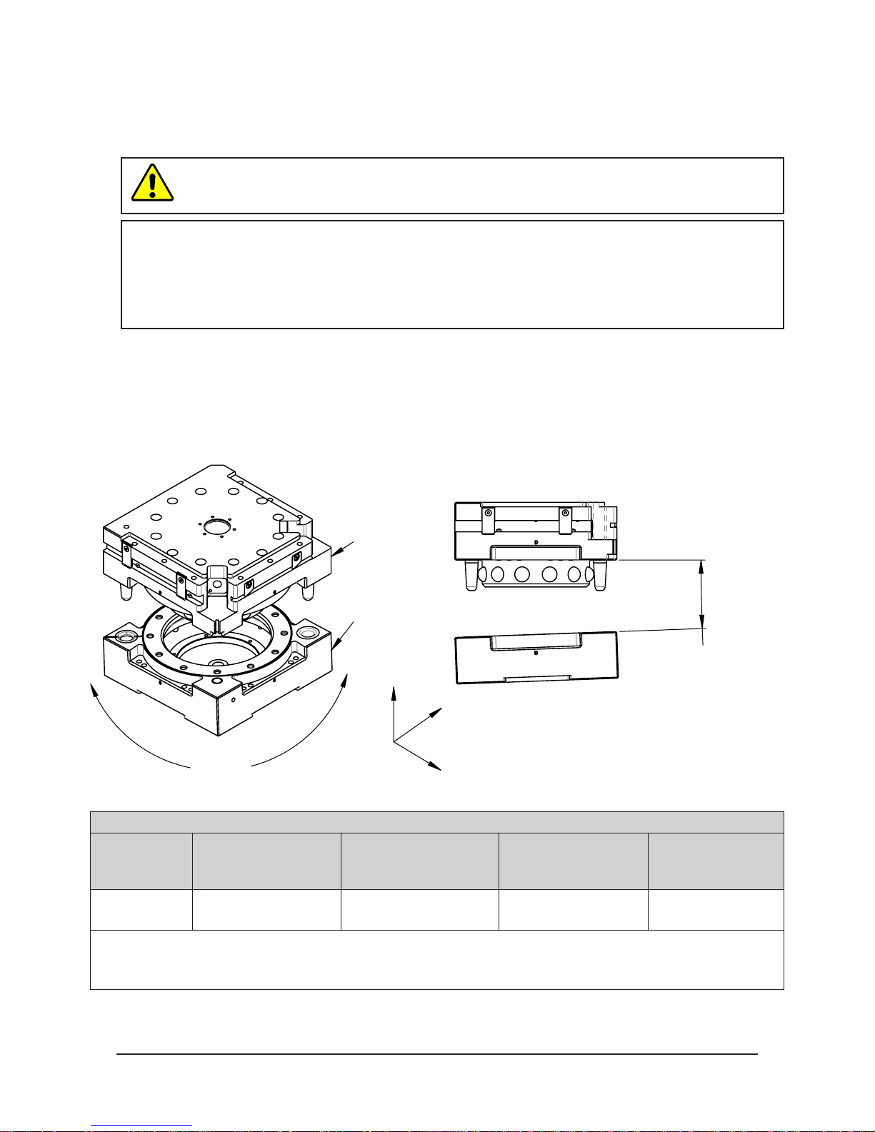
Coupling should occur with the Master plate in the No-Touch™ locking zone. As coupling occurs, the Master plate
should pull the Tool plate into the locked position.
Program the robot to minimize misalignment during coupling and uncoupling. Greater offsets can be
accommodated by the Master and Tool plates but will increase wear. Misalignments can be caused by improper tool
stand design. Refer to Tool Storage Considerations section.
Figure 3.1—OffsetDenitions
Master Plate
Tool Plate
Cocking Offset
(About X and Y)
Z
Y
X, Y, and Z Offset
Twisting
X
Table 3.1—Maximum Recommended Offsets Prior to Coupling
No-Touch Zone Z
Model
QC-210
Notes:
1. Maximum values shown. Decreasing actual values will minimize wear during coupling/uncoupling.
2. Actual allowable values may be higher in some cases but higher offsets will increase wear during coupling.
Offset
(Max)
0.08”
(2 mm)
1
X and Y Offset
2
(Max)
±0.08”
(2 mm)
Cocking Offset
(Max)
±0.7° ±1°
Twisting Offset
(Max)
Pinnacle Park • 1031 Goodworth Drive • Apex, NC 27539 • Tel: 919.772.0115 • Fax: 919.772.8259 • www.ati-ia.com • Email: info@ati-ia.com
B-14
Page 25

Manual, Robotic Tool Changer, QC-210
Document #9620-20-B-210 Series Base Tool Changer-26
3.1 Conditions for Coupling
The following conditions should be considered when operating the Tool Changer. For more details about
programming the robot, refer to the Operation section of the Control/Signal Module Manual.
CAUTION: Do not attempt to couple the Tool Changer when in the locked position. The
locking mechanism must be in the unlock position when attempting to couple the Tool
Changer. Failure to adhere to this condition may result in damage to the unit and/or the
robot. Always unlock the Master prior to coupling to a Tool.
1. Unlock the Tool Changer by removing air pressure from the lock port and supplying air pressure to the
unlock port (If equipped, the unlock sensor indicates the Tool Changer is unlocked).
NOTICE: For Tool Changers with a control/signal module and air/valve adapters with a double
solenoid valve, turn the Unlatch output on and turn the Latch output OFF. For Tool Changers
with a control/signal module and air/valve adapters with a single solenoid valve, turn the Unlatch
output ON. Some control/signal modules prevent the Tool Changer from being unlocked unless
the Master and Tool are coupled and nested properly in the tool stand, a manual override
procedure is required to unlock the Tool Changer. Refer to your Control/Signal Module Manual
for instructions.
2. Position Master above the Tool and move the Master into ready to lock position. The mating surfaces of
the Master and Tool should be parallel and not touching. Make sure that the tapered alignment pins from
the Master enter the alignment holes on the Tool. The alignment pins should be relatively concentric with
the alignment bushings with no contact between the two.
3. It is recommended that the mating faces of the Master and Tool not be touching but be within the NoTouch distance of each other when coupling to minimize stress and wear on the locking mechanism. The
locking mechanism allows the Master to “pull up” the Tool with gaps between the two sides.
CAUTION: Direct contact of the Master and Tool mating surfaces is not suggested
or required just prior to coupling. Contact may result in damage to the unit and/or the
robot. No-Touch locking technology allows the unit to couple with a separation distance
between the Master and Tool.
4. The RTL (Ready-To-Lock) sensor and target that are built into the Tool Changer must be positioned
within approximately 0.05” (1.5 mm) of each other for the sensors to detect Tool presence. RTL signals
are not required to couple the Tool Changer but are recommended as a conrmation of the coupling prior
to removing the Tool from the tool stand.
NOTICE: At this point, communication is initiated with the ATI Tool and downstream nodes. If
equipped, Tool-ID and communications become available. Depending on the type of control/
signal module, additional notications such as RTLV, TSRV, TSIV, Tool Present, Unlatch
Enabled, and other notications can provide verication of the properly functioning system
components.
5. Couple the Tool Changer by releasing the air pressure from the unlock port and supplying air pressure
to the lock port. Air must be maintained on the lock port during operation to assure rigid coupling (If
equipped, the lock sensor indicates the Tool Changer is in the locked position).
NOTICE: For Tool Changers with a control/signal module and air/valve adapters with a double
solenoid valve, turn the Unlatch output OFF and turn the Latch output ON. For Tool Changers
with a control/signal module and air/valve adapters with a single solenoid valve, turn the Unlatch
output OFF.
Pinnacle Park • 1031 Goodworth Drive • Apex, NC 27539 • Tel: 919.772.0115 • Fax: 919.772.8259 • www.ati-ia.com • Email: info@ati-ia.com
B-15
Page 26

Manual, Robotic Tool Changer, QC-210
Document #9620-20-B-210 Series Base Tool Changer-26
6. A sufcient delay must be programmed between locking valve actuation and robot motion so that the
locking process is complete before moving the robot. If equipped with Lock and Unlock sensors, the
Lock signal should read “ON” (true) and the Unlock signal should read “OFF” (false).
NOTICE: If the locking mechanism has been actuated and both the Lock and Unlock signals are
OFF, then a “missed tool” condition has occurred (for example, the Tool is not in the stand or is
not positioned properly). in this case an error should be generated and the robot program
halted. The situation requires manual inspection to determine the cause of the problem. Some
congurations will require a manual unlock of the Master plate before attempting coupling, refer
to the Control/Signal Module Manual for instructions.
NOTICE: The locking mechanism must be in the unlock state before another attempt is made to
couple or damage could occur to the robot and/or the Tool Changer.
3.2 Fail-Safe Operation
A fail-safe condition occurs when there is an unintended loss of lock air pressure to the Master plate. When
air pressure is lost, the Tool Changer relaxes and there may be a slight separation between the Master and
Tool plates. The lock sensor may indicate that the unit is not locked. ATI’s patented fail-safe feature utilizes
a multi-tapered cam to trap the ball bearings and prevent an unintended release of the Tool plate. Positional
accuracy of the tooling is not maintained during this fail-safe condition. Do not operate the Tool Changer
in the fail-safe condition. If the source air is lost to the unit, movement should be halted until air pressure is
restored.
After air pressure is re-established to the Master plate, the locking mechanism will energize and securely
lock the Master and Tool plates together. in some cases when the load on the tool changer is signicantly off
center, it may be necessary to position load underneath the tool changer or return the tool to the tool storage
location to ensure a secure lock condition. If equipped, make sure the lock sensor indicates the Tool Changer
is in the locked position before resuming normal operations. Consult your Control/Signal Module Manual
for specic error recovery information.
CAUTION: Do not use the Tool Changer in a fail-safe condition. Damage to the locking
mechanism could occur. Re-establish air pressure and ensure the Tool Changer is in a
secure lock position before returning to normal operations.
Pinnacle Park • 1031 Goodworth Drive • Apex, NC 27539 • Tel: 919.772.0115 • Fax: 919.772.8259 • www.ati-ia.com • Email: info@ati-ia.com
B-16
Page 27

Manual, Robotic Tool Changer, QC-210
Document #9620-20-B-210 Series Base Tool Changer-26
3.3 Conditions for Uncoupling
Refer to your Air/Valve Adapter and/or Control/Signal Module Manual’s Operation section for operation
during coupling/uncoupling.
1. Move the robot to position Tool plate in the tool stand. The position for coupling and uncoupling are the
same.
NOTICE: Depending on the type of control/signal module, additional notications such as
TSRV, TSIV, and other notications can provide verication of the properly functioning system
components.
2. Unlock the Tool Changer by releasing the air pressure from the lock port and supplying air pressure to
the unlock port. The Tool Changer locking mechanism moves to the unlocked position and the Tool plate
releases from the Master plate. (If equipped, the unlock sensor indicates the Tool Changer is unlocked).
NOTICE: For Tool Changers with a control/signal module and air/valve adapters with a double
solenoid valve, turn the Unlatch output on and turn the Latch output OFF. For Tool Changers
with a control/signal module and air/valve adapters with a single solenoid valve, turn the Unlatch
output ON.
CAUTION: This Tool Changer may be equipped with a tool stand Interlock (TSI)
feature that physically breaks the Unlatch solenoid circuit. Proper Use of TSI prevents
unwanted Unlock software commands from being recognized until the circuit is made.
Make sure the Tool Changer is positioned properly to tinterface plate actuate the TSI
switch when the Tool is in the tool stand.
3. A sufcient delay must be programmed between unlocking valve actuation and robot motion so that
unlocking process is complete before moving the robot. If equipped with lock and unlock sensors,
the Unlock signal should read “on” (true) and the Lock signal should read “off” (false). Any other
condition indicates a problem and the robot program should be halted. Once the Lock and Unlock
signals in the proper state, the Master plate may be moved away from the Tool plate in the axial
direction.
The robot and Master plate can now proceed to another Tool plate for coupling and subsequent operations.
3.4 ToolIdentication
When using multiple Tools, it is good practice to implement a Tool-ID system that identies each Tool with
an unique code. Tool-ID can be used to verify that the robot has picked up the proper Tool. Modules with
Tool-ID are available from ATI, refer to our Web site http://www.ati-ia.com/products/toolchanger/tool_
changer_modules.aspx for products available or contact ATI for assistance.
Pinnacle Park • 1031 Goodworth Drive • Apex, NC 27539 • Tel: 919.772.0115 • Fax: 919.772.8259 • www.ati-ia.com • Email: info@ati-ia.com
B-17
Page 28

Manual, Robotic Tool Changer, QC-210
Document #9620-20-B-210 Series Base Tool Changer-26
3.5 Tool Storage Considerations
NOTICE: Tool stand design is critical to the operation of the Tool Changer. Improperly designed
tool stands can cause jamming and excessive wear of the Tool Changer components.
Tool plates with customer tooling attached may be stored in a tool stand. ATI provides compatible tool
stands designed for durability, longevity, and maximum adaptability to t most customers’ applications. The
ATI TSL (Tool Stand Large) system is compatible with ATI Tool Changer sizes QC-150 and larger. The TSL
systems can be equipped with horizontal modules, clamp modules, and different types of tool sensing. Visit
the ATI Web Site http://www.ati-ia.com/products/toolchanger/toolstand/large/LargeStand.aspx for products
available or contact ATI for assistance.
If the customer is supplying the tool stand, it must provide a xed, repeatable, level, and stable position
for tool pick-up and drop-off. The tool stand must support the weight of the Tool Changer Tool plate, tool
interface plate, optional modules, cables, hoses, and customer tooling without that allow deection in the
excess of the offsets specied.
Ideally, the Tool should be hanging vertically in the tool stand so that gravity assists to uncouple the Tool
plate from the Master plate during unlocking. It is possible to design tool stands that hold tools in the
horizontal position, but the necessary compliance must be provided during coupling and uncoupling. in
general, “horizontal-position” tool stands cause more wear on the locking mechanism and locating features
of the Tool Changer and tool stand.
A variety of the methods may be used to position Tool in the tool stand. A common method is to use tapered
alignment pins and bushings. Robot programming and positional repeatability are vital in the Tool pick-up
and drop-off.
A sensor that detects the presence of the Tool in the tool stand is recommended. The sensor may be used
prior to coupling to ensure the Tool is seated in the stand. Sensors may also be used as the robot starts to
move away after uncoupling. Sensors provide a safety measure If a Tool becomes jammed in the stand or if
the Tool fails to release from the robot.
Proximity sensors should be positioned so that the sensing face is vertical to prevent metal shavings, weld
spatter, or other debris from the falling on the sensor and creating false readings.
Tool stands debris shields can cover Tools and modules to protect them in the dirty environments, such as
grinding or welding. Alternatively, positioning tool stands in the areas shielded from the weld spatter, uids,
adhesives, or other debris would eliminate the need for debris shields.
Pinnacle Park • 1031 Goodworth Drive • Apex, NC 27539 • Tel: 919.772.0115 • Fax: 919.772.8259 • www.ati-ia.com • Email: info@ati-ia.com
B-18
Page 29

Manual, Robotic Tool Changer, QC-210
Document #9620-20-B-210 Series Base Tool Changer-26
4. Maintenance
WARNING: Do not perform maintenance or repair(s) on the Tool Changer or modules unless
the Tool is safely supported or placed in the tool stand, all energized circuits (e.g. electrical,
air, water, etc.) are turned off, pressurized connections are purged and power is discharged
from the circuits in accordance with the customer’s safety practices and policies. Injury or
equipment damage can occur with the Tool not placed and energized circuits on. Place the
Tool in the tool stand, turn off and discharge all energized circuits, purge all pressurized
connections, and verify all circuits are de-energized before performing maintenance or
repair(s) on the Tool Changer or modules.
NOTICE: The cleanliness of the work environment strongly inuences the trouble free operation of
the Tool Changer. The dirtier the environment, the greater the need for protection against debris.
Protection of the entire EOAT, the Master, the Tool and all of the modules may be necessary. Protective
measures include the following:
• Placement of the tool stands away from the debris generators.
• Covers incorporated into the tool stands.
• Guards, deectors, air curtains, and similar devices built into the EOAT and the tool stand.
4.1 Preventive Maintenance
A visual inspection and preventive maintenance schedule is provided in table below. Detailed assembly drawings are
provided in Section 8—Drawings of this manual. Refer to module sections for detailed preventive maintenance steps for
all utility modules.
Table 4.1—Maintenance
Application(s) Tool Change Frequency Inspection Schedule
General Usage Material Handling Docking Station
Welding/Servo/Deburring, Foundry Operations (Dirty Environments) All Weekly
Checklist
Mounting Fasteners
г Inspect fasteners for proper torque, interferences, and wear. Tighten and correct as required. Refer to Table 2.1
Ball Bearings/Alignment Pins/Bushings/Bearing Race
г Inspect for wear and proper lubrication. MobilGrease XHP222 Special a NLGI #2 lithium complex grease with
molybdenum disulde additive is suggested for locking mechanism and alignment pin lubrication. Over time,
lubricants can become contaminated with debris. Therefore, it is recommended to thoroughly clean the existing
grease and replace with new as needed. See Section 4.2—Cleaning and Lubrication of the Locking Mechanism and
Alignment Pins.
г Inspect for excessive alignment pin/bushing wear, may be an indication of the poor robot position during pickup/drop-
off. Adjust robot position as needed. Check tool stand for wear and alignment problems. To replace worn alignment
pins, refer to Section 5.2.3—Alignment Pin Replacement.
г Inspect for wear on the ball bearings/bearing race, may be an indication of the excessive loading.
Sensors and Cables
г Inspect sensor cable connectors for tightness, if loose tighten connections.
г Inspect sensor cables for any damage, cuts, and abrasion. Replace as necessary. Refer to Section 5.2.1—Sensor
Replacement Procedures.
Hoses
г Inspect hose connection for tightness and leaks. If the leaking or loose secure hose connection.
г Inspect hoses for interferences, abrasions, cuts, and leaks. Replace as required.
Electrical Contacts/Pin Block (Modules)
г Inspect for damage, debris, and stuck/burnt pins. Clean pin blocks as required, refer to Section 4.3—Pin Block
Inspection and Cleaning.
Seals (Modules)
г Inspect for wear, abrasion, and cuts. Refer to Section 5.2.2—V-ring Seal Replacement
> 1 per minute Weekly
< 1 per minute Monthly
Pinnacle Park • 1031 Goodworth Drive • Apex, NC 27539 • Tel: 919.772.0115 • Fax: 919.772.8259 • www.ati-ia.com • Email: info@ati-ia.com
B-19
Page 30
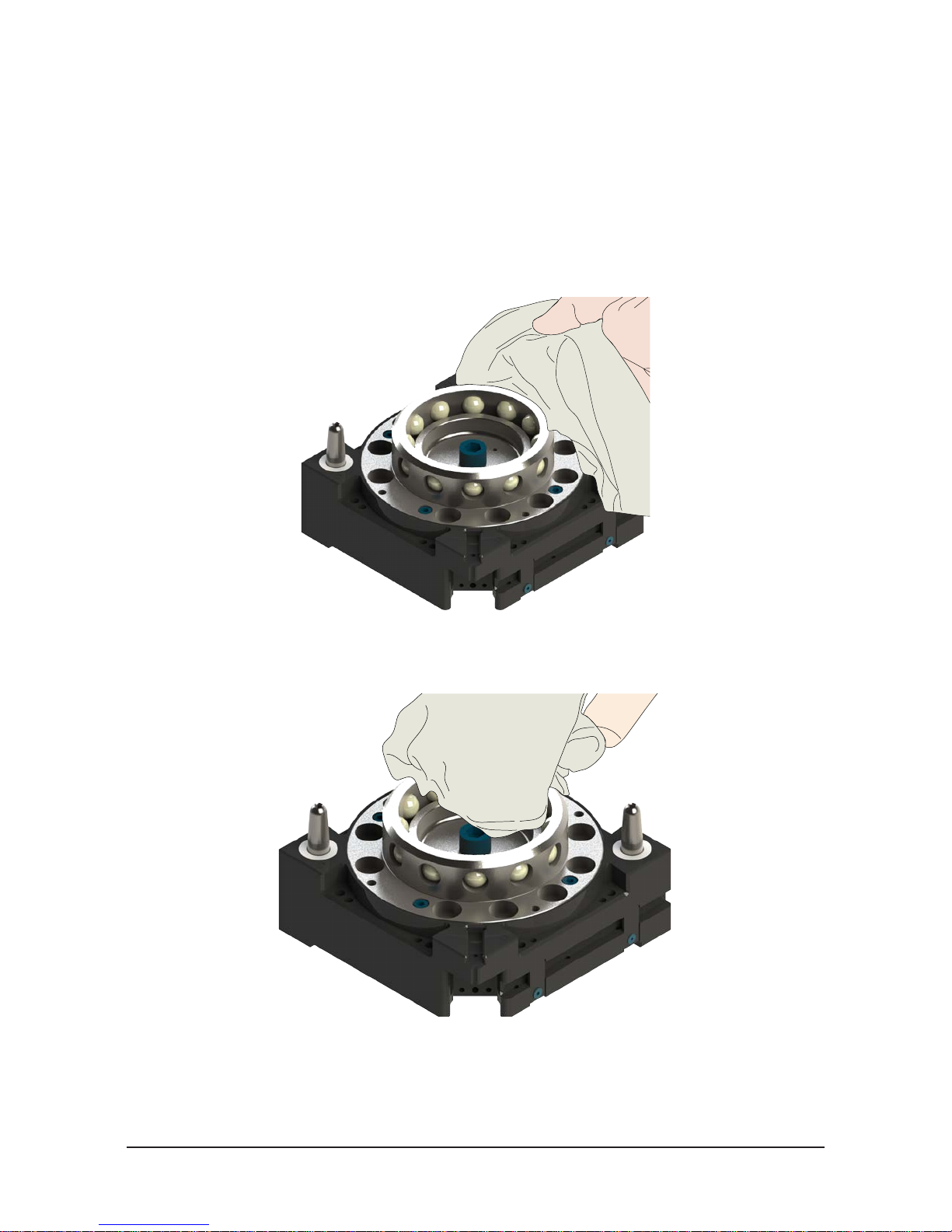
Manual, Robotic Tool Changer, QC-210
Document #9620-20-B-210 Series Base Tool Changer-26
4.2 Cleaning and Lubrication of the Locking Mechanism and Alignment Pins
Supplies required: Clean rag, MobilGrease® XHP222 Special Grease
1. Place the Tool in a secure location.
2. Uncouple the Master and Tool plates.
3. Turn off and de-energize all energized circuits (e.g. electrical, air, water, etc.).
4. Use a clean rag to thoroughly remove any lubricant and debris from the ball bearings, male coupling,
cam, and alignment pins.
Figure 4.1—Cleaning Ball Bearings and Outer Surfaces of Male Coupling
5. Use a clean rag to thoroughly remove any lubricant and debris from the inner surface of the male
coupling and cam.
Figure 4.2—Cleaning Ball Bearings, Cam and Inner Surfaces of Male Coupling
Pinnacle Park • 1031 Goodworth Drive • Apex, NC 27539 • Tel: 919.772.0115 • Fax: 919.772.8259 • www.ati-ia.com • Email: info@ati-ia.com
B-20
Page 31

Manual, Robotic Tool Changer, QC-210
Clean Bushing Surfaces
Clean Bearing Race
.
Document #9620-20-B-210 Series Base Tool Changer-26
6. Check each ball bearing to make sure it moves freely in the male coupling. Additional cleaning may be
necessary to free up any ball bearings that are sticking in place.
Figure 4.3—Check Ball Bearing Movement
7. Apply a liberal coating of the lubricant to the ball bearings, the male coupling (inside and out), and the
alignment pins.
Figure 4.4—Apply Lubricant to Locking Mechanism
Apply Lubricant on Alignment Pins
and Outer Surface of Male Coupling
Apply Lubricant on Inner
Surface of Male Coupling
Pinnacle Park • 1031 Goodworth Drive • Apex, NC 27539 • Tel: 919.772.0115 • Fax: 919.772.8259 • www.ati-ia.com • Email: info@ati-ia.com
8. Use a clean rag to thoroughly remove any lubricant and debris from the Tool plate bearing race and
bushings.
NOTICE: No application of the lubrication is necessary on the Tool plate components.
9. After the procedure is complete, resume normal operation.
Figure 4.5—Clean Tool Plate Surfaces of locking Mechanism
Surfaces
B-21
Page 32

Manual, Robotic Tool Changer, QC-210
Tool Module Pin Block
Master Module Pin Block
Note: Pin blocks shown are for
illustration purposes only.
Weld Debris
Blackened Pins
Stuck Pins
Pin Block Damage
Document #9620-20-B-210 Series Base Tool Changer-26
4.3 Pin Block Inspection and Cleaning
Tools required: Nylon Brush (ATI Part Number 3690-0000064-60)
1. Place the Tool in a secure location.
2. Uncouple the Master and Tool plates.
3. Turn off and de-energize all energized circuits (e.g. electrical, air, water, etc.).
4. Inspect the Master and Tool pin blocks for any debris or darkened pins.
Figure 4.6—Inspect Master and Tool Pin Blocks
5. If the debris or darkened pins exist, remove debris using a vacuum and clean using a nylon brush (ATI
Part Number 3690-0000064-60).
NOTICE: Do not use an abrasive media, cleaners, or solvents to clean the contact pins. Using
abrasive media, cleaners, or solvents will cause damage to the contact surface or cause pins to
stick. Clean contact surfaces with a vacuum or non-abrasive media such as a nylon brush (ATI
Part Number 3690-0000064-60)
Figure 4.7—Clean Pin Blocks with a Nylon Brush
6. Inspect the Master and Tool pin blocks for stuck pins or pin block damage.
Figure 4.8—Stuck Pin and Pin Block Damage
Note: Pin blocks shown are for
illustration purposes only.
7. If the stuck pins or pin block damage exists, contact ATI for possible pin replacement procedures or
module replacement.
8. After the procedure is complete, resume normal operation.
Pinnacle Park • 1031 Goodworth Drive • Apex, NC 27539 • Tel: 919.772.0115 • Fax: 919.772.8259 • www.ati-ia.com • Email: info@ati-ia.com
B-22
Page 33

Manual, Robotic Tool Changer, QC-210
Document #9620-20-B-210 Series Base Tool Changer-26
5. Troubleshooting and Service Procedures
The following section provides troubleshooting and service information to help diagnose conditions and repair the
Tool Changer or control/signal module.
WARNING: Do not perform maintenance or repair(s) on the Tool Changer or modules unless
the Tool is safely supported or placed in the tool stand, all energized circuits (e.g. electrical,
air, water, etc.) are turned off, pressurized connections are purged and power is discharged
from the circuits in accordance with the customer’s safety practices and policies. Injury or
equipment damage can occur with the Tool not placed and energized circuits on. Place the
Tool in the tool stand, turn off and discharge all energized circuits, purge all pressurized
connections, and verify all circuits are de-energized before performing maintenance or
repair(s) on the Tool Changer or modules.
5.1 Troubleshooting Procedures
The troubleshooting table is provided to assist in the diagnosing issues that may cause the Tool Changer not
to function properly.
Table 5.1—Troubleshooting
Symptom Cause Resolution
Tool Changer will
not lock and/or
unlock (or Lock
sensor does not
indicate Tool
Changer is Locked)
Unit is locked but
Lock signal does
not read “on”.
Unit is unlocked but
Unlock signal does
not read “on”
Read-To-Lock
(RTL) does not
read “on” when
Master and T ool
plates are mated.
Insufcient or no air pressure supply
to the lock or unlock ports.
Air pressure trapped in the deenergized Lock or Unlock ports.
Pneumatic connections loose or
damaged, solenoid cable damaged.
Debris caught between the Master
and Tool plates.
The ball bearings and/or cam are not
moving freely in the male coupling.
The Master plate and Tool plate are
not within the specied No-Touch
zone when attempting to lock.
The control/signal module or air/
valve adapter is not operating
correctly.
Lock sensor/cable is damaged.
Unlock sensor/cable is damaged.
Ready-To-Lock (RTL) sensors
not activated indicating Tool is not
positioned properly.
Verify proper air pressure and pneumatic valve is supplied. Refer
to
Section 2.7—Pneumatic Requirements.
Air pressure must be vented to the atmosphere properly,
refer to
Section 2.7—Pneumatic Requirements or refer to the
troubleshooting section of the air/valve adapter manual for more
information.
Refer to the air/valve adapter manual for more information.
Clean debris from the between Master and Tool plates. Verify
mounting fasteners is secure and does not protrude above the
mating surfaces.
Clean and lubricate as needed to restore smooth operation (see
Section 4.2—Cleaning and Lubrication of the Locking Mechanism
and Alignment Pins)
Check that the Tool is properly seated in the tool stand. Refer to
Section 3.5—Tool Storage Considerations.
Re-teach the robot to bring the Master plate and Tool plate closer
together prior to attempting to lock.
Check the troubleshooting section of the manual for the specic
module.
Replace the lock sensor assembly as necessary. Refer to
Section 5.2.1—Sensor Replacement Procedures.
Replace the unlock sensor assembly as necessary. Refer to
Section 5.2.1—Sensor Replacement Procedures.
Re-teach the robot to bring the Master plate and Tool plate
closer together prior to attempting to lock. Refer to
Operation
Check that both RTL sensors and cables are not damaged and
sensor connection to the control/signal module or air adapter
are tight. Replace damaged RTL sensors as necessary. Refer to
Section 5.2.1—Sensor Replacement Procedures.
Section 3—
Pinnacle Park • 1031 Goodworth Drive • Apex, NC 27539 • Tel: 919.772.0115 • Fax: 919.772.8259 • www.ati-ia.com • Email: info@ati-ia.com
B-23
Page 34

Manual, Robotic Tool Changer, QC-210
Document #9620-20-B-210 Series Base Tool Changer-26
Table 5.1—Troubleshooting
Symptom Cause Resolution
Units Equipped with Electrical/Servo/Control/Signal Modules
Loss of
Communication
Debris in thed around contact pins.
Contact Pin worn or damaged.
Cable connections loose or cables
damaged
Inspect V-ring seal for damage, replace damaged seal. Refer to
Section 5.2.2—V-ring Seal Replacement
Check that cable connection are secure and cables are not
damaged.
5.2 Service Procedures
The following service procedures provide instructions for component replacement.
5.2.1 Sensor Replacement Procedures
NOTICE: The Lock and Unlock sensor assemblies are precision aligned and
permanently assembled at the factory. Do not attempt to disassemble and rebuild.
Figure 5.1—Determine what type of Lock/Unlock sensors the Tool Changer uses:
Lock and Unlock Sensor
Assembly Replacement (ST and
SU Sensor Designation)
Refer to Section 5.2.1.1—Lock
and Unlock Sensor Replacement
(ST and SU Sensor Designation)
5.2.1.1 Lock and Unlock Sensor Replacement (ST and SU Sensor
Designation)
Parts required: Refer to Section 6—Serviceable Parts
Tools required: 2.5 mm Allen wrench (hex key), torque wrench
Supplies required: Loctite 222
1. Place the Tool in a secure location.
2. Uncouple the Master and Tool plates.
3. Turn off and de-energize all energized circuits (e.g. electrical, air, water, etc.).
4. Disconnect the sensor cable connector from the lock and/or unlock sensor.
5. Using a 2.5 mm Allen wrench, remove the (2) M3 socket head cap screws that
secure the lock and/or unlock sensor assembly to the Tool Changer body. Pull the
sensor assembly straight out from the Tool Changer body.
6. Remove the lock and/or unlock sensor assembly from the cable channel of the Tool
Changer body. There is an O-ring around the cylinder barrel, ensure O-ring came
off with old sensor before continuing. Discard the removed sensor assembly.
Lock and Unlock Sensor
Assembly Replacement (Serial
Numbers QM0821 and higher)
Refer to Section 5.2.1.3—Lock
and Unlock Sensor Assembly
Replacement (Serial Numbers
QM0821 and higher)
Lock and Unlock Sensor
Assembly Replacement
Refer to Section 5.2.1.4—Lock
and Unlock Sensor Assembly
Replacement (with Sensor
Assemblies)
Pinnacle Park • 1031 Goodworth Drive • Apex, NC 27539 • Tel: 919.772.0115 • Fax: 919.772.8259 • www.ati-ia.com • Email: info@ati-ia.com
B-24
Page 35

Manual, Robotic Tool Changer, QC-210
Document #9620-20-B-210 Series Base Tool Changer-26
Figure 5.2—Lock and Unlock Sensor Assembly Replacement
M3 Socket Flat Head Cap Screw
RTL Sensor Flat Pack Style RTL Sensor Flat Pack Style
Lock Sensor Assembly
Sensor Cables
M3 Socket Flat Head Cap Screw
M3 Socket Head Cap Screw
5.2.1.2 RTL Sensor Replacement (ST and SU Sensor Designation)
Unlock Sensor Assembly
7. Install the new lock and/or unlock sensor assembly, routing the cable into the cable
channel of the Tool Changer body.
8. Attach the sensor cable connectors to the lock and/or unlock sensor.
9. Insert the lock and/or unlock sensor assembly into the Tool Changer body.
10. Apply Loctite 222 to the M3 socket head cap screws. Secure the sensor assembly
with the (2) M3 socket at head screws. Tighten to 12 in-lbs (1.4 Nm) using a
2.5 mm Allen wrench.
11. Conrm the operation of the Unlock sensor by unlocking the Tool Changer and
then checking to see If the Unlock sensor cable LED is on.
12. After the procedure is complete, resume normal operation.
Refer to Figure 5.2.
Parts required: Refer to Section 6—Serviceable Parts
Tools required: 2 mm Allen wrench (hex key), torque wrench
Supplies required: Loctite 222
1. Place the Tool in a secure location.
2. Uncouple the Master and Tool plates.
3. Turn off and de-energize all energized circuits (e.g. electrical, air, water, etc.).
4. Using a 2 mm Allen wrench, remove the M3 socket at head cap screw that secure
5. Disconnect the RTL sensor cable.
6. Remove the RTL sensor from the Tool Changer body. Discard the removed RTL
7. Connect the RTL sensor cable.
8. Install the RTL sensor to the Tool Changer body.
9. Apply Loctite 222 to the M3 socket at head screws. Secure the sensor to the Tool
10. After the procedure is complete, resume normal operation.
Pinnacle Park • 1031 Goodworth Drive • Apex, NC 27539 • Tel: 919.772.0115 • Fax: 919.772.8259 • www.ati-ia.com • Email: info@ati-ia.com
the RTL sensor to the Tool Changer body.
sensor.
Changer body and tighten to 60 in-ozs (0.4 Nm) using a 2 mm Allen wrench.
B-25
Page 36

Manual, Robotic Tool Changer, QC-210
Document #9620-20-B-210 Series Base Tool Changer-26
5.2.1.3 Lock and Unlock Sensor Assembly Replacement (Serial Numbers
QM0821 and higher)
Parts required: Refer to Section 6—Serviceable Parts
Tools required: 2 mm, 2.5 mm, and 5 mm Allen wrench (hex key), torque wrench
Supplies required: Loctite 222 and 242
1. Place the Tool in a secure location.
2. Uncouple the Master and Tool plates.
3. Turn off and de-energize all energized circuits (e.g. electrical, air, water, etc.).
4. If there is an optional module on Flat D, remove the (2) M6 socket head cap screws
that secure the module(s) to the Tool Changer body using a 5 mm Allen wrench.
Refer to Figure 5.3
5. If equipped, lift off the optional modules from Flat D.
6. Using a 2 mm Allen wrench, remove the (2) M3 socket at head cap screws and
the (2) cable retaining tabs on Flat D of the Tool Changer body.
7. Unscrew the lock and/or unlock sensor cable connector from the air/valve adapter
or control/signal module.
8. Using a 2.5 mm Allen wrench, remove the (2) M3 socket head cap screws that
secure the lock and/or unlock sensor assembly to the Tool Changer body. Pull the
sensor assembly straight out from the Tool Changer body.
9. Remove the lock and/or unlock sensor assembly from the cable channel of the Tool
Changer body. There is an O-ring around the cylinder barrel, ensure O-ring came
off with old sensor before continuing. Discard the removed sensor assembly.
Figure 5.3—Lock and Unlock Sensor Assembly Replacement
Remove Module on Flat C (if required)
M6 Socket Head
Cap Screw
Lock Sensor Assembly
Unlock Sensor Assembly
M3 Socket Head Cap Screw
10. Install the new lock and/or unlock sensor assembly, routing the cable into the cable
channel of the Tool Changer body.
Valve Adapter and
Control Module on Flat A
Connects to "L"
Connects to "U"
M6 Socket Head
Cap Screw
Cable
Retaining Tab
M3 Socket Flat
Head Cap Screw
Remove Module on Flat D
11. Attach the lock and/or unlock sensor cable connectors to the proper connector on
12. Insert the lock and/or unlock sensor assembly into the Tool Changer body as shown
Pinnacle Park • 1031 Goodworth Drive • Apex, NC 27539 • Tel: 919.772.0115 • Fax: 919.772.8259 • www.ati-ia.com • Email: info@ati-ia.com
the control/signal module.
in Figure 5.3.
B-26
Page 37

Manual, Robotic Tool Changer, QC-210
Unlock (U)
Lock (L)
Green LED (Power)
Unlock (U)
Green LED (Power)
Document #9620-20-B-210 Series Base Tool Changer-26
13. Secure the sensor assembly using the (2) M3 socket at head screws. Tighten to
12 in-lbs (1.4 Nm) using a 2 mm Allen wrench.
14. Install the (2) cable retaining tabs on Flat D of the Tool Changer body and secure
with the (2) M3 socket at head cap screws. Tighten to 12 in-lbs (1.4 Nm) using a
2 mm Allen wrench.
15. If the optional modules were installed on Flat D, install the modules.
16. Apply Loctite 242 to the M6 socket head cap screws. Install the (2) M6 Socket
Head Cap Screws that secure the module to the Tool Changer body and tighten to
70 in-lbs (7.9 Nm) using a 5 mm Allen wrench.
17. Conrm the operation of the Unlock sensor by unlocking the Tool Changer and
then checking to see If the Unlock sensor cable LED is on.
Figure 5.4—Unlock Sensor Cable LEDs
Yellow LED
(Switch Made)
Lock (L)
18. Conrm the operation of the Lock sensor by locking the Tool Changer and then
checking to see If the Lock sensor cable LED is on.
Figure 5.5—Lock Sensor Cable LEDs
Yellow LED
(Switch Made)
19. After maintenance is complete, return all circuits to normal operation (e.g.
electrical, air, water, etc.).
20. After the procedure is complete, resume normal operation.
Pinnacle Park • 1031 Goodworth Drive • Apex, NC 27539 • Tel: 919.772.0115 • Fax: 919.772.8259 • www.ati-ia.com • Email: info@ati-ia.com
B-27
Page 38

Manual, Robotic Tool Changer, QC-210
Remove Module on Flat D
Document #9620-20-B-210 Series Base Tool Changer-26
5.2.1.4 Lock and Unlock Sensor Assembly Replacement (with Sensor
Assemblies)
Parts required: Refer to Section 6—Serviceable Parts
Tools required: 2 mm, 2.5 mm, and 5 mm Allen wrench (hex key), torque wrench
Supplies required: Loctite 222 and 242
1. Place the Tool in a secure location.
2. Uncouple the Master and Tool plates.
3. Turn off and de-energize all energized circuits (e.g. electrical, air, water, etc.).
4. If there is an optional module on Flat B, C, or D, remove the (2) M6 socket head
cap screws that secure the module(s) to the Tool Changer body using a 5 mm Allen
wrench. Refer to Figure 5.6
Note: If the lock sensor is being replaced the module on Flat B may need to be
removed. If the module block access to the lock sensor it will need to be removed.
5. If equipped, lift off the optional modules from Flats B, C, and D.
6. Using a 2 mm Allen wrench, remove the (2) M3 socket at head cap screws and
the (2) cable retaining tabs on Flat D of the Tool Changer body.
7. For the lock sensor, remove the (2) M3 socket at head cap screws and the (2)
cable retaining tabs on Flat C of the Tool Changer body using a 2 mm Allen
wrench.
Figure 5.6—Lock and Unlock Sensor Assembly Replacement
M6 Socket Head Cap Screws
Cable
Retaining Tab
M3 Socket Flat
Head Cap Screw
Lock Sensor
Assembly
Unlock Sensor Assembly
Remove Module
on Flat C
8. Unscrew the lock and/or unlock sensor cable connector from the air/valve adapter
or control/signal module.
9. Using a 2.5 mm Allen wrench, remove the (2) M3 socket head cap screws that
secure the lock and/or unlock sensor assembly to the Tool Changer body. Pull the
sensor assembly straight out from the Tool Changer body.
10. Remove the lock and/or unlock sensor assembly from the cable channels of the
Tool Changer body. Discard the removed sensor assembly.
Valve Adapter and
Control Module on Flat A
Connects to "L"
Connects to "U"
M6 Socket Head
Cap Screw
Cable
Retaining Tab
M3 Socket Flat
M3 Socket Head
Cap Screw
Head Cap Screw
11. Install the new lock and/or unlock sensor assembly, routing the cable into the cable
12. Attach the lock and/or unlock sensor cable connectors to the proper connector on
Pinnacle Park • 1031 Goodworth Drive • Apex, NC 27539 • Tel: 919.772.0115 • Fax: 919.772.8259 • www.ati-ia.com • Email: info@ati-ia.com
channels of the Tool Changer body.
the air adapter or control/signal module.
B-28
Page 39

Manual, Robotic Tool Changer, QC-210
Document #9620-20-B-210 Series Base Tool Changer-26
13. Insert the lock and/or unlock sensor assembly into the Tool Changer body.
14. Apply Loctite 222 to the M3 socket at head screws, secure the sensor assembly
using the (2) M3 socket at head screws and tighten to 12 in-lbs (1.4 Nm) using a
2.5 mm Allen wrench.
15. Install the (2) cable retaining tabs on Flat D of the Tool Changer body and secure
with the (2) M3 socket at head cap screws. Tighten to 12 in-lbs (1.4 Nm) using a
2 mm Allen wrench.
16. For the lock sensor, install the (2) cable retaining tabs on Flat C of the Tool
Changer body and secure with the (2) M3 socket at head cap screws. Tighten to
12 in-lbs (1.4 Nm) using a 2 mm Allen wrench.
17. If the optional modules were removed from Flats B, C, and D, install the modules.
18. Apply Loctite 242 to the M6 socket head cap screws. Install the (2) M6 Socket
Head Cap Screws that secure the module(s) to the Tool Changer and tighten to
70 in-lbs (7.9 Nm) using a 5 mm Allen wrench.
19. Conrm the operation of the Unlock sensor by unlocking the Tool Changer and
then checking to see If the Unlock sensor in-body LED is on.
20. Conrm the operation of the Lock sensor by locking the Tool Changer and then
checking to see If the Lock sensor in-body LED is on.
21. After the procedure is complete, resume normal operation.
Pinnacle Park • 1031 Goodworth Drive • Apex, NC 27539 • Tel: 919.772.0115 • Fax: 919.772.8259 • www.ati-ia.com • Email: info@ati-ia.com
B-29
Page 40

Manual, Robotic Tool Changer, QC-210
Valve Adapter and Control Module on Flat A
Document #9620-20-B-210 Series Base Tool Changer-26
5.2.1.5 RTL Flat Pack Style Sensor Replacement (R2 Sensor)
Parts required: Refer to Section 6—Serviceable Parts
Tools required: 2 mm and 5 mm Allen wrench (hex key), torque wrench
Supplies required: Loctite 222 and 242
1. Place the Tool in a secure location.
2. Uncouple the Master and Tool plates.
3. Turn off and de-energize all energized circuits (e.g. electrical, air, water, etc.).
4. If there is an optional module on Flat D, remove the (2) M6 socket head cap screws
that secure the module to the Tool Changer body using a 5 mm Allen wrench.
5. If equipped, lift off the optional modules from Flat D.
6. Using a 2 mm Allen wrench, remove the (2) M3 socket at head cap screws and
the (2) cable retaining tabs on Flat D of the Tool Changer body.
7. Using a 2 mm Allen wrench, remove the M3 socket at head cap screw that secure
the RTL sensor to the Tool Changer body.
8. Unscrew the RTL sensor cable connector from the air adapter or control/signal
module.
9. Remove the RTL sensor from the cable channel of the Tool Changer body. Discard
the removed RTL sensor.
Figure 5.7—RTL Sensor Replacement (R2 Sensor)
M3 Socket Flat Head Cap Screw
RTL Sensor Flat Pack Style
Connects to "R2"
M6 Socket Head
Cap Screw
Cable Retaining Tab
M3 Socket Flat Head Cap Screw
Remove Module on Flat D
10. Install the new RTL sensor, routing the cable into the cable channel of the Tool
Changer body.
11. Attach the RTL sensor cable to the R2 connector on the air/valve adapter or
control/signal module.
12. Install the RTL sensor to the Tool Changer body.
13. Apply Loctite 222 to the M3 socket at head screws. Secure the sensor to the Tool
14. Install the (2) cable retaining tabs on Flat D of the Tool Changer body and secure
Pinnacle Park • 1031 Goodworth Drive • Apex, NC 27539 • Tel: 919.772.0115 • Fax: 919.772.8259 • www.ati-ia.com • Email: info@ati-ia.com
Changer body and tighten to 60 in-ozs (0.4 Nm) using a 2 mm Allen wrench.
with the (2) M3 socket at head cap screws. Tighten to 12 in-lbs (1.4 Nm) using a
2 mm Allen wrench.
B-30
Page 41

Manual, Robotic Tool Changer, QC-210
Green LED (Power)
Document #9620-20-B-210 Series Base Tool Changer-26
15. If the optional module was removed from Flat D, install the module.
16. Apply Loctite 242 to the M6 socket head cap screws. Install the (2) M6 Socket
Head Cap Screws that secure the module to the Tool Changer body and tighten to
70 in-lbs (7.9 Nm) using a 5 mm Allen wrench.
17. Conrm the operation of the RTL sensor by bringing a metallic object into close
proximity to the face of the sensor and watching for the LED in the sensor cable to
light up.
Figure 5.8—RTL (R2) Sensor Cable LEDs
RTL (R2)
Yellow LED
(Switch Made)
18. After the procedure is complete, resume normal operation.
Pinnacle Park • 1031 Goodworth Drive • Apex, NC 27539 • Tel: 919.772.0115 • Fax: 919.772.8259 • www.ati-ia.com • Email: info@ati-ia.com
B-31
Page 42

Manual, Robotic Tool Changer, QC-210
Document #9620-20-B-210 Series Base Tool Changer-26
5.2.1.6 RTL Flat Pack Style Sensor Replacement (R1 Sensor)
Parts required: Refer to Section 6—Serviceable Parts
Tools required: 2 mm and 3 mm Allen wrench (hex key), torque wrench
Supplies required: Loctite 222
1. Place the Tool in a secure location.
2. Uncouple the Master and Tool plates.
3. Turn off and de-energize all energized circuits (e.g. electrical, air, water, etc.).
4. Depending on the robot and interface plate used the Tool Changer Master plate
may have to be removed. Refer to Section 2.3—Master Plate Removal.
5. Using a 2 mm Allen wrench, remove the (2) M3 socket at head cap screws and
(2) cable retaining tabs on the air/valve adapter or the (3) M5 socket at head
cap screws and Master cleat using a 3 mm Allen wrench. Refer to Figure 5.9 and
Figure 5.10.
6. Using a 2 mm Allen wrench, remove the M3 socket at head cap screw that secure
the RTL sensor assembly to the Tool Changer body.
7. Unscrew the RTL sensor cable connector from the air adapter or control/signal
module.
8. Remove the RTL sensor from the cable channel of the air/valve adapter. Discard
the removed RTL sensor.
Figure 5.9—RTL Sensor Assembly Replacement using Retaining Tabs (R1 Sensor)
Cable Retaining Tab
RTL Sensor
Flat Pack Style
M3 Socket Flat Head
Cap Screw
Valve Adapter and Control Module on Flat A
M3 Socket Flat Head Cap Screw
Connects to "R1"
Pinnacle Park • 1031 Goodworth Drive • Apex, NC 27539 • Tel: 919.772.0115 • Fax: 919.772.8259 • www.ati-ia.com • Email: info@ati-ia.com
B-32
Page 43

Manual, Robotic Tool Changer, QC-210
Green LED (Power)
Document #9620-20-B-210 Series Base Tool Changer-26
Figure 5.10—RTL Sensor Assembly Replacement using Master Cleat (R1 Sensor)
Master Cleat
RTL Sensor
Flat Pack Style
M3 Socket Flat Head
Cap Screw
9. Install the new RTL sensor, routing the cable into the cable channel of the air/valve
adapter.
10. Attach the RTL sensor cable to the R1 connector on the air adapter or control/
signal module.
11. Install the RTL sensor assembly to the Tool Changer body.
12. Apply Loctite 222 to the M3 socket at head screws. Secure the sensor to the Tool
Changer body and tighten to 60 in-ozs (0.4 Nm) using a 2 mm Allen wrench.
(3) M5 Socket Flat Head Cap Screw
Connects to "R1"
Air/Valve Adapter and
Control Module on Flat A
13. If the removed, install the (2) cable retaining tabs on the air/valve adapter and
secure with the (2) M3 socket at head cap screws. Tighten to contact using a
2 mm Allen wrench. If the removed, install the Master cleat and apply Loctite 222
to the (3) M5 socket at head cap screws. Secure the Master cleat with the (3)
M5 socket head cap screw and tighten to 28 in-lbs (3.2 Nm) using a 3 mm Allen
wrench.
14. Conrm the operation of the RTL sensor by bringing a metallic object into close
proximity to the face of the sensor and watching for the LED in the sensor cable to
light up.
NOTICE: Some control/signal modules supply power to the RTL sensors
in series. The RTL (R2) sensor will have to be switched before power is
supplied to the RTL (R1) sensor. If this is the case bring a metallic object into
close proximity of the both the RTL (R1 and R2) sensor.
Figure 5.11—RTL (R2) Sensor Cable LEDs
Yellow LED
(Switch Made)
RTL (R2)
15. Install the Master plate to the robot arm or interface plate, refer to Section 2.2—
16. After the procedure is complete, resume normal operation.
Pinnacle Park • 1031 Goodworth Drive • Apex, NC 27539 • Tel: 919.772.0115 • Fax: 919.772.8259 • www.ati-ia.com • Email: info@ati-ia.com
Master Plate Installation.
B-33
Page 44

Manual, Robotic Tool Changer, QC-210
Document #9620-20-B-210 Series Base Tool Changer-26
5.2.2 V-ring Seal Replacement
Parts required: Refer to Section 6—Serviceable Parts
The seal protects the electrical connection between the Master and Tool module. If the seal
becomes worn or damaged, it must be replaced.
1. Place the Tool in a secure location.
2. Uncouple the Master and Tool plates.
3. Turn off and de-energize all energized circuits (e.g. electrical, air, water, etc.).
4. To remove the existing seal, pinch the edge of the seal with your ngers and pull the seal away
from the pin block on the Master.
5. To install a new seal, stretch the new seal over the shoulder of the pin block.
6. Push the seal hub down against the pin block using your nger tip.
7. After the procedure is complete, resume normal operation.
Figure 5.12—V-ring Seal Replacement
Stretch seal over shoulder of pin block
and push seal hub down against
V-ring Seal
the pin block with finger tip
V-ring Seal
Pinch edge of seal with
fingers and gently pull
away from pin block
Pinnacle Park • 1031 Goodworth Drive • Apex, NC 27539 • Tel: 919.772.0115 • Fax: 919.772.8259 • www.ati-ia.com • Email: info@ati-ia.com
B-34
Page 45

Manual, Robotic Tool Changer, QC-210
Document #9620-20-B-210 Series Base Tool Changer-26
5.2.3 Alignment Pin Replacement
Parts required: Refer to Section 6—Serviceable Parts
Tools required: 3 mm or 4 mm Allen wrench (hex key), torque wrench
Supplies required: Clean rag, Loctite 242, MobilGrease XHP222
1. Place the Tool in a secure location.
2. Uncouple the Master and Tool plates.
3. Turn off and de-energize all energized circuits (e.g. electrical, air, water, etc.).
4. Unscrew the alignment pin assembly from the Master plate using a 4 mm Allen Wrench (see
Figure 5.13). If the alignment pin cannot be removed using the Allen Wrench in the tip, go to
step 5. If the alignment was remove the go to step 7.
NOTICE: If the for any reason the pin cannot be removed using the Allen Wrench in the
tip, it may be necessary to remove the it by other means, such as locking pliers.
Figure 5.13—4 mm Allen Wrench
Ratchet Wrench
Set Screw
Master Plate
4 mm Allen Wrench Socket
Alignment Pin Assembly
5. Another approach would be to use the access hole in the back side of the Master plate. If no,t
already removed, remove the Master plate refer to Section 2.3—Master Plate Removal. Use a
3 mm Allen wrench to remove the alignment pin from the back side of the Master plate. Refer
to Figure 5.14.
Figure 5.14—3 mm Allen Wrench
Ratchet Wrench
3 mm Allen Wrench Socket
Master Plate
6. Once the alignment pin has been removed, verify that the assembly (pin and set screw) are
intact. If the set screw portion of the assembly did not come out, it will be necessary to remove
the it separately using the access hole in the back plate of the Master plate.
7. Apply Loctite 242 and install the new alignment pin assembly into the bushing on the Tool
Changer. Tighten to 60 in-lbs (6.8 Nm) using a 4 mm Allen wrench.
8. Apply MobilGrease XHP222 Special grease to the alignment pin (see Section 4.2—Cleaning
and Lubrication of the Locking Mechanism and Alignment Pins).
9. After the procedure is complete, resume normal operation.
Pinnacle Park • 1031 Goodworth Drive • Apex, NC 27539 • Tel: 919.772.0115 • Fax: 919.772.8259 • www.ati-ia.com • Email: info@ati-ia.com
Set Screw
Alignment Pin Assembly
B-35
Page 46

Manual, Robotic Tool Changer, QC-210
Document #9620-20-B-210 Series Base Tool Changer-26
6. Serviceable Parts
6.1 Models 9121-210xM-0-0-0-0-S0
2
4
5
Figure 5.15—Master Plate
Item No. Qty Part Number Description
1 1 9121-210xM-0-0-0-0-S0 QC-210 Base Master, No Options, with plugs in the sensor holes
2 2 9005-20-2241 1/2” (2) Piece Pin Assembly
3 2 3410-0001016-01 O-ring 1/16 x 1/8 I.D. x 1/4 O.D.
4 2 9005-20-1983 Sensor Bore Cover Plate Assembly, SS Screws
5 2 3500-1058008-21A
Notes:
M3 x 8 Socket Head Cap Screw, SS, ND Ind. Microspheres Epoxy, Yellow.
0-3 uncoated lead thds. 5-7 coated thds
3
1
x = A, B, C, D, E, or F for boss size designation.
Pinnacle Park • 1031 Goodworth Drive • Apex, NC 27539 • Tel: 919.772.0115 • Fax: 919.772.8259 • www.ati-ia.com • Email: info@ati-ia.com
B-36
Page 47

Manual, Robotic Tool Changer, QC-210
Document #9620-20-B-210 Series Base Tool Changer-26
6.2 Models 9121-210xM-0-0-0-0-SL and 9121-210xM-0-0-0-0-SE
8
11
9
3
10
1
2
8
6
5
7
12
Item No. Qty Part Number Description
1 1 9121-210xM-0-0-0-0-SL QC-210 Master and PNP lock/unlock and RTL Sensing, LED Cables
1 1 9121-210xM-0-0-0-0-SE QC-210 Master and NPN lock/unlock and RTL Sensing
2 2 9005-20-2241 1/2” (2) Piece Pin Assembly
3 2 3410-0001016-01 O-ring 1/16 x 1/8 I.D. x 1/4 O.D.
4 2 3700-20-4092 Large Cable Retaining Tab
5 4 3500-1258006-11
6 2 3700-20-3292 Cable Retaining T ab
7 4 3500-1057006-15 M3 x 6 socket head cap screws, Class 12.9, Blue dyed Magni-565
8 2 3500-1258010-11
9 1 8590-9909999-138 LED PNP Flat Pack Sensor .3 M Lg (90 Pico)
10 1 8590-9909999-137 RTL2 LED PNP Flat Pack Sensor .28 M (90 Pico)
11 1 9005-20-1359 QC-210 Lock Sensor Carrier Assembly, PNP, LED
12 1 9005-20-1360 QC-210 UnLock Sensor Carrier Assembly, PNP, LED
9 1 8590-9909999-85 LED NPN Flat Pack Sensor, 0.3 m Long, 90 deg Pico
10 1 8590-9909999-86 LED NPN Flat Pack Sensor, 0.28 m Long, 90 deg Pico
11 1 9005-20-1375 QC-210 Lock Sensor Carrier Assembly, NPN
12 1 9005-20-1376 QC-210 Unlock Sensor Carrier Assembly, NPN
7
Figure 5.16—QC-210 Master Plates
M3 x 6 mm Flat Head Socket Cap Screw Black Oxide
M3 x 10 mm Flat Head Socket Cap Screw Black Oxide
9121-210xM-0-0-0-0-SL
9121-210xM-0-0-0-0-SE
Notes:
4
5
x = A, B, C, D, E, or F for boss size designation.
Pinnacle Park • 1031 Goodworth Drive • Apex, NC 27539 • Tel: 919.772.0115 • Fax: 919.772.8259 • www.ati-ia.com • Email: info@ati-ia.com
B-37
Page 48

Manual, Robotic Tool Changer, QC-210
Document #9620-20-B-210 Series Base Tool Changer-26
6.3 Models 9121-210xM-0-0-0-0-SM, 9121-210xM-0-0-0-0-SP and 9121-210xM-0-00-0-SR
2
6
10
1
7
9
9
4
5
Figure 5.17—QC-210 Master Plates
Item No. Qty Part Number Description
1 1 9121-210xM-0-0-0-0-SM QC-210 Master and PNP lock/unlock and RTL Sensing, LED Cables
1 1 9121-210xM-0-0-0-0-SP QC-210 Master and NPN lock/unlock and RTL Sensing, LED Cables
1 1 9121-210xM-0-0-0-0-SR
2 2 9005-20-2241 1/2” (2) Piece Pin Assembly
3 2 3410-0001016-01 O-ring 1/16 x 1/8 I.D. x 1/4 O.D.
4 2 3700-20-4092 Large Cable Retaining Tab
5 2 3500-1258006-11
6 2 3500-1258010-11 M3 x 10 mm Flat Head Socket Cap Screw Black Oxide
7 4 3500-1057006-15 M3 x 6 socket head cap screws, Class 12.9, Blue dyed Magni-565
8 1 8590-9909999-138 LED PNP Flat Pack Sensor .3 M Lg (90 Pico)
9 2 9005-20-1743 Lock/Unlock Sensor Assembly, QC-210 (PNP)
10 1 8590-9909999-137 RTL2 LED PNP Flat Pack Sensor .28 M (90 Pico)
8 1 8590-9909999-85 LED NPN Flat Pack Sensor, 0.3 m Long, 90 deg Pico
9 2 9005-20-1744 Lock/Unlock Sensor Assembly, QC-210 (NPN)
10 1 8590-9909999-86 LED NPN Flat Pack Sensor, 0.28 m Long, 90 deg Pico
8 1 8590-9909999-90 PNP Flat Pack Sensor 1 M Lg, Straight Pico
9 2 9005-20-1446 Lock/Unlock Carrier Assembly, QC-50
10 1 8590-9909999-90 PNP Flat Pack Sensor 1 M Lg, Straight Pico
QC-210 Master and PNP lock/unlock and RTL Sensing, RTL 1 m cables & 5 m
lock/unlock cables
M3 x 6 mm Flat Head Socket Cap Screw Black Oxide
9121-210xM-0-0-0-0-SM
9121-210xM-0-0-0-0-SP
9121-210xM-0-0-0-0-SR
3
Notes:
6
8
x = A, B, C, D, E, or F for boss size designation.
Pinnacle Park • 1031 Goodworth Drive • Apex, NC 27539 • Tel: 919.772.0115 • Fax: 919.772.8259 • www.ati-ia.com • Email: info@ati-ia.com
B-38
Page 49

Manual, Robotic Tool Changer, QC-210
Document #9620-20-B-210 Series Base Tool Changer-26
6.4 Models 9121-210xM-0-0-0-0-ST and 9121-210xM-0-0-0-0-SU
2
6
8
3
1
10
9
9
10
4
5
7
7
Figure 5.18—QC-210 Master Plates
Item No. Qty Part Number Description
1 1
9121-210xM-0-0-0-0-SM QC-210 Master and PNP lock/unlock and RTL Sensing, LED Cables
9121-210xM-0-0-0-0-SP QC-210 Master and NPN lock/unlock and RTL Sensing, LED Cables
2 2 9005-20-2241 1/2” (2) Piece Pin Assembly
3 2 3410-0001016-01 O-ring 1/16 x 1/8 I.D. x 1/4 O.D.
4 2 3700-20-4092 Large Cable Retaining Tab
5 2 3500-1258006-11
M3 x 6 mm Flat Head Socket Cap Screw Black Oxide
6 2 3500-1258010-11 M3 x 10 mm Flat Head Socket Cap Screw Black Oxide
7 4 3500-1057006-15 M3 x 6 socket head cap screws, Class 12.9, Blue dyed Magni-565
9121-210xM-0-0-0-0-ST
8 2 8590-9909999-150 PNP Flat Prox 5M long (no conn) Turck Bi2-Q5.5-AP6X 5 M
9 2 9005-20-1917 PNP Lock/Unlock Sensor Subassembly with LED
10 2 8590-9909999-15
High-ex cable with straight screw-on connector, 5 M (16.4 ft.) long with ying
leads
9121-210xM-0-0-0-0-SU
8 2 8590-9909999-172 NPN Flat Pack Sensor, 5 Meter, Flying Leads Bi2-Q5.5-AN6X 5 M
9 2 9005-20-1918 Lock/Unlock Sensor Assembly, (NPN)
10 2 8590-9909999-15
High-ex cable with straight screw-on connector, 5 M (16.4 ft.) long with ying
leads
Notes:
6
8
x = A, B, C, D, E, or F for boss size designation.
Pinnacle Park • 1031 Goodworth Drive • Apex, NC 27539 • Tel: 919.772.0115 • Fax: 919.772.8259 • www.ati-ia.com • Email: info@ati-ia.com
B-39
Page 50

Manual, Robotic Tool Changer, QC-210
Document #9620-20-B-210 Series Base Tool Changer-26
6.5 Standard Tool Plate
1
3
2
4
Table 5.2—Standard Tool Plate
Item No. Qty Part Number Description
1 1 9121-210CT-0-0-0-0
2 1 9005-20-1335 Tool back cover plate for QC-210 (Includes Items 3 and 4)
3 6 3500-1262006-15A
4 1 4010-0000020-01 Grommet C-30-SG-16A
Tool with 100 mm Recess and no other options
M4x6 Flat Head Socket Cap Screw, Class 10.9, Blue dyed Magni-565, ND
Microspheres Epoxy, Yellow.
Pinnacle Park • 1031 Goodworth Drive • Apex, NC 27539 • Tel: 919.772.0115 • Fax: 919.772.8259 • www.ati-ia.com • Email: info@ati-ia.com
B-40
Page 51

Manual, Robotic Tool Changer, QC-210
Document #9620-20-B-210 Series Base Tool Changer-26
6.6 Bolt-Down Tool Plate
2
1
5
3
4
Table 5.3—Bolt-Down Tool Plate
Item No. Qty Part Number Description
1 1 9121-210CWT-0-0-0-0
2 1 9005-20-1335 Tool back cover plate for QC-210 (Includes Items 3 and 4)
3 6 3500-1262006-15A
4 1 4010-0000020-01 Grommet C-30-SG-16A
5 1 3700-20-4783 Bearing Race, QC-210 Bolt-Down
Tool with 100 mm Recess and Bolt-Down Option
M4x6 Flat Head Socket Cap Screw, Class 10.9, Blue dyed Magni-565, ND
Microspheres Epoxy, Yellow.
Pinnacle Park • 1031 Goodworth Drive • Apex, NC 27539 • Tel: 919.772.0115 • Fax: 919.772.8259 • www.ati-ia.com • Email: info@ati-ia.com
B-41
Page 52

Manual, Robotic Tool Changer, QC-210
Document #9620-20-B-210 Series Base Tool Changer-26
7. Specications
Table 5.4—Master and Standard Tool Plates
Recommended Max Payload 661 lbs. (300kg) The mass attached to the Tool Changer.
Operating Temperature Range
Operating Pressure Range
Coupling Force @ 80 psi
Recommended Max Moment
X-Y (Mxy)
-20–150°F
(-30–66°C)
60–100 psi
(4.1–6.9 bar)
7,000 lbs
(3,175 kg)
24,000 in-lbs
2,712 (Nm)
Optimal operating temperature range.
Locking mechanism supply pressure operating range.
Supply to be clean, dry, and ltered to 50 micron or
better.
Axial holding force
Maximum recommended working load for optimum
performance of the Tool Changer
Recommended Max Torque
about Z (Mz)
Positional Repeatability
Weight (coupled, no access.) 18 lbs. (8.2 kg) Master 12 lbs (5.4 kg) / Tool 6 lbs (2.7 kg)
Max. Recommended distance
between Master and Tool
plate
Sensor Information, signal
name
Mounting/Customer Interface
Recommended Max Moment
X-Y (Mxy)
Weight (coupled, no access.) 17.5 lbs. (7.9 kg) Master 12 lbs (5.4 kg) / Tool 5.5 lbs (2.5 kg)
Mounting/Customer Interface
20,000 in-lbs
2,260 (Nm)
0.0006”
(0.015 mm)
0.08”
(2 mm)
L/U
(Lock/Unlock)
RTL
(Ready-To-Lock)
Master plate
Tool plate
Table 5.5—Bolt-Down Tool Plate
18,000 in-lbs
2,034 (Nm)
Bolt-Down Tool
plate
Maximum recommended working torque for optimum
performance of the Tool Changer
Repeatability tested at rated load at one million cycles.
No-Touch locking technology allows the Master and
Tool plates to lock with separation when coupling.
Internal proximity sensors (2) with cable and connector
for direct wiring to the control/signal module to indicate
locking mechanism position.
Flat Pack proximity sensor with cable and connector
for direct wiring to control/signal module to indicate
Master and Tool mating surfaces within close proximity
of each other.
Meets ISO 9409-1-A125
Meets ISO 9409-1-A125
Also supports (8) Fasteners on the 160 mm BC
Pattern
NOTE: This value is lower than the standard
QC-210 Tool Changer. This is the maximum
recommended working load for optimum
performance of the Tool Changer.
(12) Through-holes for M8 socket head cap screws on
the BC 132.5 mm
Pinnacle Park • 1031 Goodworth Drive • Apex, NC 27539 • Tel: 919.772.0115 • Fax: 919.772.8259 • www.ati-ia.com • Email: info@ati-ia.com
B-42
Page 53

Manual, Robotic Tool Changer, QC-210
Document #9620-20-B-210 Series Base Tool Changer-26
8. Drawings
8.1 QC-210 Tool Changer
Date
4/15/2014
7/30/2015
SZJ
LJH
Initiator
Flat C
30°
Typ.
Description
30
Pin
Coupled
10.6
From Far Side
for M10 SHCS
Customer Interface
10X C'Bored
57.1
Master
Eco 11974; Alignment was 9005-20-1200, now 9005-20-
2241.
Eco 13528; Added depth to dowel pin holes
05
06
Rev.
103.1
[4.06"]
125
B.C.
Flat D
Flat B
12
06
(Slip Fit)
10
Equally Spaced
2X
Flat A
See Note 2
Master Side
Customer Interface
Master Side
(projection only)
06
REVISION
ISO 9001 Registered Company
Fax: +1.919.772.8259 www.ati-ia.com
Tel: +1.919.772.0115 Email: info@ati-ia.com
1031 Goodworth Drive, Apex, NC 27539, USA
MANNER EXCEPT ON ORDER OR WITH PRIOR WRITTEN AUTHORIZATION OF ATI.
PROPERTY OF ATI INDUSTRIAL AUTOMATION, INC. NOT TO BE REPRODUCED IN ANY
TITLE
NOTES: UNLESS OTHERWISE
SPECIFIED.
DO NOT SCALE DRAWING.
ALL DIMENSIONS ARE IN
MILLIMETERS.
9630-20-210
DRAWING NUMBER
B
SIZE
1:2
SCALE
QC-210 Base Tool Changer
3
1
SHEET OF
D. Swanson 1/22/09
D. Norton 6/4/09
PROJECT #
DRAWN BY:
CHECKED BY:
3rd ANGLE PROJECTION
46.1
20
125
(Slip Fit)
B.C.
10
Equally Spaced
Customer Interface
2X
Flat C
8
H7
100
Tool
18
Customer Interface
8X Tapped M12X1.75
30°
4X
(See Note 1)
Customer Interface
Flat B
30°
4X
Flat D
160
20
Equally Spaced
Customer Interface
6X Tapped M10X1.5
30°
& Tool
Master
Square
Tool Side
20
(Slip Fit)
10
Customer Interface
12
(Slip Fit)
12
Customer Interface
Tool Cover
(with air block spacer installed)
Flat A
160
B.C.
Notes:
1) Tool cover must be removed to utilize full depth of this customer interface feature.
Tool Side
(projection only)
With tool cover in place usable feature depth is 2mm.
2) Optional Master side mounting bosses available.
Scale 1:2.5
Pinnacle Park • 1031 Goodworth Drive • Apex, NC 27539 • Tel: 919.772.0115 • Fax: 919.772.8259 • www.ati-ia.com • Email: info@ati-ia.com
B-43
Page 54

3rd ANGLE PROJECTION
8
12
15
14
16
1
3
17
2
10
11
4
13
7
6
QC-210 Master Assembly
Rev.
Description
Initiator
Date
-
See Sheet1
- -
B
1:2.25
2
3
REVISION
NOTES: UNLESS OTHERWISE
SPECIFIED.
DO NOT SCALE DRAWING.
ALL DIMENSIONS ARE IN
MILLIMETERS.
DRAWN BY:
CHECKED BY:
D. Swanson 1/22/09
D. Norton 6/4/09
TITLE
SCALE
SIZE
DRAWING NUMBER
PROJECT #
SHEET OF
9630-20-210
06
PROPERTY OF ATI INDUSTRIAL AUTOMATION, INC. NOT TO BE REPRODUCED IN ANY
MANNER EXCEPT ON ORDER OR WITH PRIOR WRITTEN AUTHORIZATION OF ATI.
1031 Goodworth Drive, Apex, NC 27539, USA
Tel: +1.919.772.0115 Email: info@ati-ia.com
Fax: +1.919.772.8259 www.ati-ia.com
ISO 9001 Registered Company
QC-210 Base Tool Changer
Manual, Robotic Tool Changer, QC-210
Document #9620-20-B-210 Series Base Tool Changer-26
Pinnacle Park • 1031 Goodworth Drive • Apex, NC 27539 • Tel: 919.772.0115 • Fax: 919.772.8259 • www.ati-ia.com • Email: info@ati-ia.com
B-44
Page 55

Manual, Robotic Tool Changer, QC-210
Document #9620-20-B-210 Series Base Tool Changer-26
Date
- -
Initiator
See Sheet1
Description
-
Rev.
?
7
06
REVISION
ISO 9001 Registered Company
Fax: +1.919.772.8259 www.ati-ia.com
Tel: +1.919.772.0115 Email: info@ati-ia.com
1031 Goodworth Drive, Apex, NC 27539, USA
MANNER EXCEPT ON ORDER OR WITH PRIOR WRITTEN AUTHORIZATION OF ATI.
PROPERTY OF ATI INDUSTRIAL AUTOMATION, INC. NOT TO BE REPRODUCED IN ANY
TITLE
D. Swanson 1/22/09
DRAWN BY:
9630-20-210
DRAWING NUMBER
B
SIZE
1:2
SCALE
QC-210 Base Tool Changer
3 3
SHEET OF
D. Norton 6/4/09
PROJECT #
CHECKED BY:
1
QC-210 Tool Assembly
5
3
NOTES: UNLESS OTHERWISE
SPECIFIED.
DO NOT SCALE DRAWING.
ALL DIMENSIONS ARE IN
MILLIMETERS.
3rd ANGLE PROJECTION
8
6
4
Pinnacle Park • 1031 Goodworth Drive • Apex, NC 27539 • Tel: 919.772.0115 • Fax: 919.772.8259 • www.ati-ia.com • Email: info@ati-ia.com
B-45
Page 56

Manual, Robotic Tool Changer, QC-210
Document #9620-20-B-210 Series Base Tool Changer-26
8.2 Bolt-Down Tool Plate
Date
7/2/2007
9/17/2009
9/6/2012
10/19/2012
07
REVISION
CF
CF
Initiator
Description
Eco 5578; Replaced 3710-20-3330 with 3700-20-5274.
Eco 7246; Removed Nylon Tip Set Screw 3500-1964008-32
and Changed 3500-1972020-22 to 22A (Pre Applied).
03
04
Rev.
CF
LJH 1/7/2011
MSD
Eco 10275; Corrected Busing Mates in Assembly Model.
Removed Note 3.
Eco 8241; 3505-0868007-12 was 3505-0868004-12
Eco 10082; Change race cover fastener to "Pre/14 in-lbs"
from "222/14 in-lbs".
07
06
05
Pre / 14 in-lbs
9
-- / Note 3
3
-- / Note 3
4
DESCRIPTION
M8 x 55mm SHCS, Blue Dyed Magni-565
Scale 1:2
Isometric View
PART NUMBER
3500-1068055-15
QTY.
1 2
ITEM NO.
Microspheres
M8 Flat Washer
QC-210 Tool Body
Bearing Race, QC-210 Bolt Down
M8 Hex Nut Zinc Plated Steel, 7mm high
M12 x 20mm Lg Set Screw Flat Point SST, ND
3505-0868007-12
3510-5068001-12
3500-1972020-22A
Drill Bushing 1/2" dia, 7/8 OD, 1" long
Elongated Drill Bushing 1/2" dia, 7/8 OD, 1" long
3700-20-4202
3700-20-4783
3700-20-5274
3700-20-4026
ISO 9001 Registered Company
Fax: +1.919.772.8259 www.ati-ia.com
Tel: +1.919.772.0115 Email: info@ati-ia.com
1031 Goodworth Drive, Apex, NC 27539, USA
Race Cover_QC 210 Tool Sub-Assembly
MANNER EXCEPT ON ORDER OR WITH PRIOR WRITTEN AUTHORIZATION OF ATI.
PROPERTY OF ATI INDUSTRIAL AUTOMATION, INC. NOT TO BE REPRODUCED IN ANY
QC-210 Bolt Down Base Tool Assembly, No Options,
100mm Recess
TITLE
9005-20-1335
R. Heavner, 2/15/06
B.Digeso, 3/2/06
1
DRAWN BY:
CHECKED BY:
2 2
6
3 2
4 2
7 1
8 1
5 1
9 1
NOTES: UNLESS OTHERWISE
SPECIFIED.
DO NOT SCALE DRAWING.
ALL DIMENSIONS ARE IN
MILLIMETERS.
9121-210CWT-0-0-0-0
DRAWING NUMBER
B
SIZE
1:1.5
SCALE
1 1
SHEET OF
060215-2
PROJECT #
3rd ANGLE PROJECTION
5
Pinnacle Park • 1031 Goodworth Drive • Apex, NC 27539 • Tel: 919.772.0115 • Fax: 919.772.8259 • www.ati-ia.com • Email: info@ati-ia.com
6
Note 1
2
Pre / Note 2
B-46
-- / Note 3
1
8
7
DO NOT APPLY LOCTITE!
When installing bushing into tool body, align orientation marks 1.on both parts.
Install set screw flush with the tool body.
M8 Fastener, M8 flat washer, and M8 nut are used for shipping
only.
Assembly Notes:
2.
3.
Page 57

Manual, Control/Signal Module, Adapter Assembly, JJ43
Document #9620-20-C-JJ43-02
C. Control and Signal Modules
JJ43—Control and Signal Module, Adapter Assembly
No Manual exists for this control and signal module. A drawing is attached.
For additional information, please refer to our catalog or contact our Sales department. We
will be glad to assist you.
How to Reach Us
Sale, Service and Information about ATI products:
A TI Industrial Automation
1031 Goodworth Drive
Apex, NC 27539 USA
www.ati-ia.com
Tel: 919.772.0115
Fax: 919.772.8259
E-mail: info@ati-ia.com
Technical support and questions:
Application Engineering
Tel: 919.772.0115, Option 2, Option 2
Fax: 919.772.8259
E-mail: mech_support@ati-ia.com
Pinnacle Park • 1031 Goodworth Drive • Apex, NC 27539 • Tel: 919.772.0115 • Fax: 919.772.8259 • www.ati-ia.com • Email: info@ati-ia.com
C-1
Page 58

Manual, Control/Signal Module, Adapter Assembly, JJ43
Document #9620-20-C-JJ43-02
Date
01/03/2017
Ledge Mount
Initiator
DSS
52.2
J16 Mounting
Description
Initial Issue
Rev.
01
Pattern
41.2
J16 Mounting
Pattern
01
REVISION
ISO 9001 Registered Company
Fax: +1.919.772.8259 www.ati-ia.com
Tel: +1.919.772.0115 Email: info@ati-ia.com
1031 Goodworth Drive, Apex, NC 27539, USA
MANNER EXCEPT ON ORDER OR WITH PRIOR WRITTEN AUTHORIZATION OF ATI.
PROPERTY OF ATI INDUSTRIAL AUTOMATION, INC. NOT TO BE REPRODUCED IN ANY
TITLE
D. Swanson 1/3/17
9630-20-JJ43
DRAWING NUMBER
B
SIZE
1:2.25
SCALE
JJ43 Ledge Mount Adapter - QC Ledge Mount Spacer w/
J16 Patterns On Each End
1 1
SHEET OF
D. Wagner 1/3/17
-
61
158.8
Typ.
12.7
Typ.
12.7
JJ43 Master
J16 Mounting
Pattern
JJ43 Tool
J16 Mounting
Pattern
DRAWN BY:
CHECKED BY:
NOTES: UNLESS OTHERWISE
SPECIFIED.
DO NOT SCALE DRAWING.
ALL DIMENSIONS ARE IN
MILLIMETERS.
PROJECT #
3rd ANGLE PROJECTION
Pinnacle Park • 1031 Goodworth Drive • Apex, NC 27539 • Tel: 919.772.0115 • Fax: 919.772.8259 • www.ati-ia.com • Email: info@ati-ia.com
93.7
Coupled
(Approx.)
C-2
Note:
The Adapter may interfere with adjacent modules. Please consult an ATI Application Engineer.
Page 59

Manual, Air Adapters
Document #9620-20-C-Jxx Air Adapters-02
Table of Contents
C. Control and Signal Modules ..................................................................................................C-2
Air Adapters
..................................................................................................................................C-2
1. Product Overview ..................................................................................................................C-2
2. Installation .............................................................................................................................C-4
2.1 Air Adapter Installation for QC-113, QC-210, QC-213, GL6L, GL7L ...................................... C-4
2.2 Air Adapter Removal for QC-113, QC-210, QC-213, GL6L, GL7L0 ........................................C-5
2.3 Air Adapter Installation for QC-310, QC-313, QC-510, QC-1210 ............................................ C-6
2.4 Air Adapter Removal for QC-310, QC-313, QC-510, QC-1210 ................................................ C-7
2.5 T ool Adapter Assembly Installation ......................................................................................... C-7
2.6 T ool Adapter Assembly Removal ............................................................................................. C-8
2.7 Pneumatic Connections ...........................................................................................................C-8
2.7.1 Valve Requirements and Connections for the Locking Mechanism ............................... C-8
3. Operation ...............................................................................................................................C-9
4. Maintenance ...........................................................................................................................C-9
5. Troubleshooting and Service Procedures ..........................................................................C-9
5.1 Troubleshooting ........................................................................................................................C-9
5.2 Service Procedures ...................................................................................................................C-9
6. Serviceable Parts ................................................................................................................C-10
6.1 Air Adapters ............................................................................................................................. C-10
6.2 T ool Adapter Assembly ...........................................................................................................C-10
7. Specications ......................................................................................................................C-11
8. Drawings ..............................................................................................................................C-12
8.1 Air Adapter for QC-210............................................................................................................ C-12
8.2 Air Adapter for QC-310............................................................................................................ C-13
Pinnacle Park • 1031 Goodworth Drive • Apex, NC 27539 • Tel: 919.772.0115 • Fax: 919.772.8259 • www.ati-ia.com • Email: info@ati-ia.com
C-1
Page 60

Manual, Air Adapters
Document #9620-20-C-Jxx Air Adapters-02
C. Control and Signal Modules
Air Adapters
1. Product Overview
Air adapters are required to provide an air supply to the compatible Tool Changer or Utility Coupler Master for
actuation of the locking mechanism. Air adapters mount to Flat ‘A’. Many variations of the air adapter are available,
depending upon the Tool Changer size and type of porting required by the customer (see Table 1.1 and Section 8—
Drawings for a complete listing of available adapters and customer drawings)
Table 1.1—Air Adapters
Air Adapter Description Air Port Size Compatible Tool Changer
or Utility Coupler models
9121-JA2-M Air Adapter 1/4” NPT QC-113, QC-210, QC-213, GL6L, GL7L
9121-JA3-M Air Adapter 1/4” NPT QC-310, QC-313, QC-510, QC-1210
9121-JB2-M Air Adapter (BSPP) G 1/4 QC-113, QC-210, QC-213, GL6L, GL7L
9121-JB3-M Air Adapter (BSPP) G 1/4 QC-310, QC-313, QC-510, QC-1210
9121-JB4-M Air Adapter W/ SST Mounting screws (BSPP) G 1/4 QC-310, QC-313, QC-510, QC-1210
9121-JB8-M Air Adapter W/ Reversed Air Ports (BSPP) G 1/4 QC-113, QC-210, QC-213, GL6L, GL7L
9121-JP2-M Air Adapter 1/4 BSPT QC-113, QC-210, QC-213, GL6L, GL7L
9121-JP3-M Air Adapter 1/4 BSPT QC-310, QC-313, QC-510, QC-1210
The air adapter provides a ledge mount for the control/signal Master module and provides a Lock and Unlock
air port connection for the customer air supply. Lock and Unlock air connections to the Tool Changer or Utility
Coupler are provided through ports in the ledge mount, O-rings in the body seal the connection. The customer
is require to supply a 2-position 4-way or 5-way air valve for the Lock and Unlock air connection, refer to
Section 2.7—Pneumatic Connections for more information, refer to Figure 1.2.
Figure 1.2—Air Adapters
Ledge Mounting for
Control/Signal Module
Common Ledge
Mounting Feature
1/4 NPT Lock Air Port
1/4 NPT Unlock Air Port
9121-JA2-M (Shown)
Ledge Mounting for
Control/Signal Module
Common Ledge
Mounting Feature
1/4 NPT Unlock Air Port
1/4 NPT
Lock Air Port
9121-JA3-M (Shown)
Pinnacle Park • 1031 Goodworth Drive • Apex, NC 27539 • Tel: 919.772.0115 • Fax: 919.772.8259 • www.ati-ia.com • Email: info@ati-ia.com
C-2
Page 61

Manual, Air Adapters
Document #9620-20-C-Jxx Air Adapters-02
A tool adapter assembly (9005-20-1192) is required for the Tool side which provides the proper spacing and a ledge
mount for the control/signal Tool module.
Figure 1.3—T ool Adapters Assembly
Tool Adapter Assembly
(9005-20-1192)
Ledge Mount Feature for
Control/Signal Tool Module
Pinnacle Park • 1031 Goodworth Drive • Apex, NC 27539 • Tel: 919.772.0115 • Fax: 919.772.8259 • www.ati-ia.com • Email: info@ati-ia.com
C-3
Page 62

Manual, Air Adapters
Document #9620-20-C-Jxx Air Adapters-02
2. Installation
Air adapters and tool adapter assemblies are typically installed by ATI prior to shipment. The steps below outline
the eld installation or removal as required.
WARNING: Do not perform maintenance or repair on Tool Changer or modules unless
the Tool is safely supported or docked in the tool stand, all energized circuits (e.g.
electrical, air, water, etc.) are turned off, pressurized connections purged and power
discharged from circuits in accordance with the customer’s safety practices and
policies. Injury or equipment damage can occur with Tool not docked and energized
circuits on. Dock the Tool safely in the tool stand, turn off and discharge all energized
circuits, purge all pressurized connections, verify all energized circuits are de-energized
before performing maintenance or repair on Tool Changer or modules.
2.1 Air Adapter Installation for QC-113, QC-210, QC-213, GL6L, GL7L
Tools required: 5 mm Allen wrench (hex key), , 4 mm Allen wrench (hex key), torque wrench
Supplies required: clean rag
1. If the Tool Changer is already installed, dock the Tool side of the Tool Changer safely in the tool stand
and uncouple the Tool Changer to allow clear access to the Master and Tool plates of the Tool Changer.
2. Turn off and de-energize all energized circuits (e.g. electrical, air, water, etc.).
3. It may be necessary to clean the mounting surface on the Tool Changer prior to installing the valve
adapter in order to remove any debris that may be present.
4. (2) O-rings are required on the Master side Flat ‘A’ interface. Make sure these O-rings are present and
lightly lubricated (refer to Figure 2.1).
5. Using the ledge feature as a guide place the air adapter adjacent to the ‘Flat A’ mounting surface. Align
the air adapter using the dowels in the bottom of the ledge feature. Apply Loctite 242 to the supplied M6
socket head cap screws. Secure the air adapter using the M6 socket head cap screws and tighten to 70
in-lbs (7.9 Nm).
6. Apply Loctite 222 to the (2) supplied M5 socket head cap screws. Secure the air adapter using the
fasteners, tighten to 55 in-lbs (6.2 Nm).
Figure 2.1—Air Adapter Installation (QC-210 Shown)
Tool Changer Master
(2) M6 Socket
Head Cap Screws
(QC-210 Shown)
(2) O-rings
Air Adapter
9121-JA2-M
(Shown)
RTL (R1) Sensor Cable
Pneumatic Connections
(2) M5 Socket
Head Cap Screws
(2) Cable Retaining Tabs
Pinnacle Park • 1031 Goodworth Drive • Apex, NC 27539 • Tel: 919.772.0115 • Fax: 919.772.8259 • www.ati-ia.com • Email: info@ati-ia.com
Cable Channel in Bottom of Air Adapter Module
(2) M3 Socket Flat Head Cap Screws
C-4
Page 63

Manual, Air Adapters
(Shown for Reference)
Document #9620-20-C-Jxx Air Adapters-02
7. Route the RTL (R1) sensor cable through the cable channel in the bottom of the air adapter. Refer to
Figure 2.2.
8. Install the (2) M3 socket at head screws and the (2) cable retaining tabs from the bottom of the air
adapter to secure the RTL (R1) cable. Tighten to 24 in-oz.
9. Make pneumatic connections to the air adapter housing as required. Ensure that the connectors are
cleaned prior to being secured as appropriate. ATI recommends using a thread sealant such as Loctite
569 or similar.
Figure 2.2—RTL (R1) Sensor Cable Routing
Cable Channel in
Bottom of Air Adapter
Air Adapter
9121-JA2-M (Shown)
Tool Changer Master
(QC-210 Shown)
RTL (R1)
Sensor Cable
(2) Cable Retaining Tabs
Control/Signal Module
2.2 Air Adapter Removal for QC-113, QC-210, QC-213, GL6L, GL7L0
NOTICE: Depending on maintenance or repair being performed, utilities to modules and Master
plate may need to be disconnected.
Tools required: 5 mm Allen wrench (hex key), 4 mm Allen wrench (hex key)
1. If the Tool Changer is already installed, dock the Tool side of the Tool Changer safely in the tool stand
and uncouple the Tool Changer to allow clear access to the Master and Tool plates of the Tool Changer.
2. Turn off and de-energize all energized circuits (e.g. electrical, air, water, etc.).
3. Remove the control/signal module off the air adapter. Refer to the control /signal module manual for
instructions.
4. Remove the (2) M3 socket at head cap screws and the (2) cable retaining tabs from the bottom of the
air adapter.
5. Remove the RTL (R1) sensor cable from the cable channel in the bottom of the air adapter.
6. Remove the (2) M5 socket head cap screws and the (2) M6 socket head cap screws and lift the air
adapter off the Tool Changer.
7. Make sure that the O-rings are retained at the Master side Flat ‘A’ mounting interface.
Pinnacle Park • 1031 Goodworth Drive • Apex, NC 27539 • Tel: 919.772.0115 • Fax: 919.772.8259 • www.ati-ia.com • Email: info@ati-ia.com
C-5
Page 64

Manual, Air Adapters
Document #9620-20-C-Jxx Air Adapters-02
2.3 Air Adapter Installation for QC-310, QC-313, QC-510, QC-1210
Tools required: 5 mm Allen wrench (hex key), 4 mm Allen wrench (hex key), torque wrench
Supplies required: clean rag
1. If the Tool Changer is already installed, dock the Tool side of the Tool Changer safely in the tool stand
and uncouple the Tool Changer to allow clear access to the Master and Tool plates of the Tool Changer.
2. Turn off and de-energize all energized circuits (e.g. electrical, air, water, etc.).
3. It may be necessary to clean the mounting surface on the Tool Changer or Utility Coupler prior to
installing the air adapter in order to remove any debris that may be present.
4. (2) O-rings are required on the Master side Flat ‘A’ interface. Make sure these O-rings are present and
lightly lubricated (refer to Figure 2.3).
NOTICE: Makes sure the RTL (R1) sensor cable is completely in the cable channel in the Tool
Changer body, so it will not get pinched when installing the air adapter.
5. Using the ledge feature to place the air adapter adjacent to the ‘Flat A’ mounting surface. Align the air
adapter using the dowels in the bottom of the ledge feature. Apply Loctite 242 to the supplied M6 socket
head cap screws. Secure the air adapter using the M6 socket head cap screws and tighten to 70 in-lbs (7.9
Nm).
6. Apply Loctite 222 to the (2) supplied M5 socket head cap screws. Secure the air adapter using the
fasteners and tighten the M5 socket head cap screws to 55 in-lbs (6.2 Nm).
7. Make pneumatic connections to the air adapter housing as required. Ensure that the connectors are
cleaned prior to being secured as appropriate. ATI recommends using a thread sealant such as Loctite
569 or similar.
Figure 2.3—Air Adapter Installation (QC-310 Shown)
Lock, Unlock, and
RTL R1 and R2 Connectors
(2) M6 Socket Head Cap Screws
Valve Adapter
9121-JA3-M (Shown)
(2) M6 Socket Head
Cap Screws
Control/Signal
Module
(2) M5 Socket
Head Cap Screws
Unlock
Air Port
(2) O-rings
Lock
Air Port
RTL (R1)
Sensor Cable
Pneumatic
Connections
Tool Changer
(QC-310 Shown)
Pinnacle Park • 1031 Goodworth Drive • Apex, NC 27539 • Tel: 919.772.0115 • Fax: 919.772.8259 • www.ati-ia.com • Email: info@ati-ia.com
C-6
Page 65

Manual, Air Adapters
Document #9620-20-C-Jxx Air Adapters-02
2.4 Air Adapter Removal for QC-310, QC-313, QC-510, QC-1210
NOTICE: Depending on maintenance or repair being performed, utilities to modules and Master
plate may need to be disconnected.
Tools required: 5 mm Allen wrench (hex key), 4 mm Allen wrench (hex key)
1. If the Tool Changer is already installed, dock the Tool side of the Tool Changer safely in the tool stand
and uncouple the Tool Changer to allow clear access to the Master and Tool plates of the Tool Changer.
2. Turn off and de-energize all energized circuits (e.g. electrical, air, water, etc.).
3. Remove the control/signal module off the air adapter. Refer to the control /signal module manual for
instructions.
4. Remove the (2) M5 socket head cap screws and the (2) M6 socket head cap screws and lift the air
adapter off the Tool Changer.
5. Make sure that the O-rings are retained at the Master side Flat ‘A’ mounting interface.
2.5 T ool Adapter Assembly Installation
Tools required: 5 mm Allen wrench (hex key), 4 mm Allen wrench (hex key), torque wrench
Supplies required: clean rag
1. If the Tool Changer is already installed, dock the Tool side of the Tool Changer safely in the tool stand
and uncouple the Tool Changer to allow clear access to the Master and Tool plates of the Tool Changer.
2. Turn off and de-energize all energized circuits (e.g. electrical, air, water, etc.).
3. It may be necessary to clean the mounting surface on the Tool Changer or Utility Coupler prior to
installing the air adapter in order to remove any debris that may be present.
4. Using the ledge feature as a guide, place the tool adapter assembly adjacent to the ‘A’ mounting surface.
Align the tool adapter assembly using the dowels in the bottom of the ledge feature. Apply Loctite 242 to
the supplied M6 socket head cap screws. Secure the tool adapter assembly using the M6 socket head cap
screws and tighten to 89 in-lbs (10.0 Nm).
5. Apply Loctite 222 the (2) supplied M5 socket head cap screws. Secure the tool adapter assembly using
the M5 socket head cap screws and tighten to 55 in-lbs (6.2 Nm).
Figure 2.4—T ool Adapter Assembly Installation
(2) M6 Socket Head Cap Screws
(9005-20-1192) Tool Adapter Assembly
(2) M6 Socket Head
Control/Signal
Pinnacle Park • 1031 Goodworth Drive • Apex, NC 27539 • Tel: 919.772.0115 • Fax: 919.772.8259 • www.ati-ia.com • Email: info@ati-ia.com
Cap Screws
Tool Module
(2) M5 Socket Head Cap Screws
Tool Change Tool Plate
(QC-310 Shown)
C-7
Page 66

Manual, Air Adapters
- 100 psi (4.1 - 6.9 Bar)
Air Adapter
Document #9620-20-C-Jxx Air Adapters-02
2.6 T ool Adapter Assembly Removal
NOTICE: Depending on maintenance or repair being performed, utilities to modules may need
to be disconnected.
Tools required: 5 mm Allen wrench (hex key), 4 mm Allen wrench (hex key)
1. If the Tool Changer is already installed, dock the Tool side of the Tool Changer safely in the tool stand
and uncouple the Tool Changer to allow clear access to the Master and Tool plates of the Tool Changer.
2. Turn off and de-energize all energized circuits (e.g. electrical, air, water, etc.).
3. Remove the control/signal module off the tool adapter assembly. Refer to the control /signal module
manual for instructions.
4. Remove the (2) M5 socket head cap screws and the (2) M6 socket head cap screws and lift the tool
adapter assembly off the Tool Changer or Utility Coupler. (refer to Figure 2.4).
2.7 Pneumatic Connections
The air supply used for coupling and uncoupling the Tool Changer should be clean, dry, and non-lubricated.
A supply pressure in the range of 60 to 100 psi is acceptable for operation of the locking mechanism, with a
setting of 80 psi suggested. The air should be ltered 40 micron or better.
CAUTION: Do not use the Tool Changer in a fail-safe condition. Do not transport the
Tool Changer in a fail-safe condition. Possible damage to the locking mechanism could
occur. Re-establish air pressure to Tool Changer before returning to normal operations.
2.7.1 Valve Requirements and Connections for the Locking Mechanism
When an air adapter is utilized that does not contain an integrated solenoid valve, it is required that
a customer supplied 2-position 4-way or 5-way valve be used to actuate the locking mechanism
in the Master plate. It is imperative that when air is supplied to the Lock or Unlock Port on the
Master plate, that the opposite port be vented to atmosphere (i.e., when air is supplied to the Lock
Port, the Unlock Port must be open to the atmosphere.) Failure to vent trapped air or vacuum on the
inactive port may inhibit proper shuttling of the valve and prevent coupling and/or uncoupling from
occurring.
CAUTION: The locking mechanism will not function properly when connected
to a 3-way valve as this type of valve is incapable of venting trapped air
pressure from within the Tool Changer. This could result in damage to the
product, attached tooling, or personnel. Connect the Lock and Unlock supply
air to a 2-position 4-way or 5-way valve.
Figure 2.5— Lock and Unlock Pneumatic Connections
4 or 5-way Valve
Supply Clean, Dry,
Lock Port
Unlock Port
Exhaust
Open to Atmosphere
Non-lubricated Air
60
Pinnacle Park • 1031 Goodworth Drive • Apex, NC 27539 • Tel: 919.772.0115 • Fax: 919.772.8259 • www.ati-ia.com • Email: info@ati-ia.com
C-8
Page 67

Manual, Air Adapters
Document #9620-20-C-Jxx Air Adapters-02
3. Operation
It is important that the air adapter be supplied with clean, dry, non-lubricated air supplied between 60 and 100 psi
(4.5–6.9 Bar) and ltered at 40 microns or better. The Tool Changer is operated by supplying air to the lock port or
the air adapter to lock the Tool Changer. The Lock air must be maintained during operation and the unlock air must
be vented to the atmosphere using a 2-position 4-way or 5-way valve, refer to Section 2.7—Pneumatic Connections
for more information. To Unlock the Tool Changer air must be supplied to the unlock port on the air adapter and the
lock air must be vented to the atmosphere.
4. Maintenance
Air adapters should require no maintenance. There are no wear components, the sensor connections should be
inspected for looseness and tighten if necessary. Pneumatic connection should be inspected for leaks or damage to
hoses.
WARNING:Do not perform maintenance or repair on Tool Changer or modules unless the
Tool is safely supported or docked in the tool stand, all energized circuits (e.g. electrical,
air, water, etc.) are turned off, pressurized connections purged and power discharged from
circuits in accordance with the customer’s safety practices and policies. Injury or equipment
damage can occur with Tool not docked and energized circuits on. Dock the Tool safely in the
tool stand, turn off and discharge all energized circuits, purge all pressurized connections,
verify all energized circuits are de-energized before performing maintenance or repair on Tool
Changer or modules.
5. Troubleshooting and Service Procedures
The following section provides troubleshooting information to help diagnose conditions with the Tool Changer or
air adapter and service procedures to help resolve these conditions.
5.1 Troubleshooting
Follow the suggested actions listed in Table 5.1 when attempting to troubleshoot the air adapter. If issues persist,
contact your closest ATI representative.
Table 5.1—Troubleshooting
Symptom Cause Resolution
Customer supplied exhaust
mufer is clogged.
No or not enough air
pressure on the pneumatic
connection.
Tool Changer will
not Lock / Unlock or
operates slowly.
Loose air adapter or O-rings
leaking or missing.
Customer supplied solenoid
valve not operating properly
5.2 Service Procedures
There are no specic service procedures for the air adapter.
Check/Replace exhaust mufer; ensure clean air supply.
Make sure Pneumatic connection has minimum pressure, refer to
Section 2.7—Pneumatic Connections.
Verify that the fasteners connecting the control/signal Module to the
air adapter are properly tightened. If air still leaking, remove the air
adapter from the Tool Changer and check for air leaks, damaged
or missing O-rings., Refer to
QC-113, QC-210, QC-213, GL6L, GL7L0 or Section 2.4—Air Adapter
Removal for QC-310, QC-313, QC-510, QC-1210
Check customer supplied solenoid valve for damage, proper venting,
refer to
Section 2.7—Pneumatic Connections.
Section 2.2—Air Adapter Removal for
Pinnacle Park • 1031 Goodworth Drive • Apex, NC 27539 • Tel: 919.772.0115 • Fax: 919.772.8259 • www.ati-ia.com • Email: info@ati-ia.com
C-9
Page 68

Manual, Air Adapters
Document #9620-20-C-Jxx Air Adapters-02
6. Serviceable Parts
6.1 Air Adapters
Refer to Section 8—Drawings for Air Adapter serviceable parts.
6.2 T ool Adapter Assembly
1
2
3
Table 5.2—T ool Adapter Assembly
ITEM NO. QTY PART NUMBER DESCRIPTION
1 1 9005-20-1192 Tool Adapter Assembly
2 2 3500-1066016-15A M6 x 16mm SHCS MB ND Microspheres
3 2 3500-1064035-15A M5 x 35mm SHCS MB, ND Microspheres
Pinnacle Park • 1031 Goodworth Drive • Apex, NC 27539 • Tel: 919.772.0115 • Fax: 919.772.8259 • www.ati-ia.com • Email: info@ati-ia.com
C-10
Page 69

Manual, Air Adapters
Document #9620-20-C-Jxx Air Adapters-02
7. Specications
Table 5.3—AirAdapterSpecications
All Air Adapter Models Specication
Air Pressure 60 - 100 psi (4.1 – 6.9 Bar) clean, dry, non-lubricated air
Air Filtration 50 microns
9121-JA2-M Air Adapter NPT, QC-113, QC-210, QC-213, GL6L, GL7L
Pneumatic Connection 1/4” NPT
Weight 1.64 lbs (0.744 kg)
9121-JA3-M Air Adapter NPT, QC-310, QC-313, QC-510, QC-1210
Pneumatic Connection 1/4” NPT
Weight 1.92 lbs (0.87 kg)
9121-JB2-M Air Adapter G, QC-113, QC-210, QC-213, GL6L, GL7L
Pneumatic Connection G 1/4
Weight 1.66 lbs (0.75 kg)
9121-JB3-M Air Adapter G, QC-310, QC-313, QC-510, QC-1210
Pneumatic Connection G 1/4
Weight 1.94 lbs (0.88 kg)
9121-JB4-M Air Adapter with SST Mounting Screws G, QC-310, QC-313, QC-510, QC-1210
Pneumatic Connection G 1/4
Weight 1.94 lbs (0.88 kg)
9121-JB8-M Air Adapter with Revered Air Ports G, QC-113, QC-210, QC-213, GL6L, GL7L
Pneumatic Connection G 1/4
Weight 1.66 lbs (0.75 kg)
9121-JP2-M Air Adapter BSPT, QC-113, QC-210, QC-213, GL6L, GL7L
Pneumatic Connection 1.64 lbs (0.744 kg)
Weight xxx lbs (xxx kg)
9121-JP3-M Air Adapter BSPT, QC-310, QC-313, QC-510, QC-1210
Pneumatic Connection 1/4” BSPT
Weight 1.92 lbs (0.87 kg)
Table 5.4—ToolAdapterAssemblySpecications
9005-20-1192
Weight
Pinnacle Park • 1031 Goodworth Drive • Apex, NC 27539 • Tel: 919.772.0115 • Fax: 919.772.8259 • www.ati-ia.com • Email: info@ati-ia.com
Tool Adapter Assembly, QC-210, QC-213, QC-310, QC-313, QC-510, QC-1210, GL6L,
or GL7L
1.33 lbs (0.603 kg)
C-11
Page 70

Manual, Air Adapters
Document #9620-20-C-Jxx Air Adapters-02
8. Drawings
8.1 Air Adapter for QC-210
Date
1/7/2016
JGH
Initiator
Description
ECO13408. Drawing Release.
02
Rev.
1
02
REVISION
7
3
4
DESCRIPTION
M5-0.8 x 35mm SHCS, Blue
M6-1 x 20mm SHCS, Blue, Pre-Applied
M3 x 6mm SFHCS Black Oxide
ISO 9001 Registered Company
Fax: +1.919.772.8259 www.ati-ia.com
Tel: +1.919.772.0115 Email: info@ati-ia.com
1031 Goodworth Drive, Apex, NC 27539, USA
Cable Retaining Tab
MANNER EXCEPT ON ORDER OR WITH PRIOR WRITTEN AUTHORIZATION OF ATI.
PROPERTY OF ATI INDUSTRIAL AUTOMATION, INC. NOT TO BE REPRODUCED IN ANY
TITLE
9630-20-Jxx Air Adapters for QC-210
DRAWING NUMBER
B
SIZE
1:2
SCALE
Air Adapter, QC-210
158.8
56.7
2
31.8
9121-JA2-M Air Adapter (Shown)
Ledge Mount
1
PART NUMBER
3500-1064035-15
3500-1066020-15A
3500-1258006-11
3700-20-3292
QTY
ITEM
NO.
1 2
2 2
3 2
4 2
NOTES: UNLESS OTHERWISE
SPECIFIED.
DO NOT SCALE DRAWING.
ALL DIMENSIONS ARE IN
MILLIMETERS.
1 1
SHEET OF
J. Handy, 1/7/16
W Berrocal, 9/9/16
PROJECT #
DRAWN BY:
CHECKED BY:
3rd ANGLE PROJECTION
Ledge Mount
Pinnacle Park • 1031 Goodworth Drive • Apex, NC 27539 • Tel: 919.772.0115 • Fax: 919.772.8259 • www.ati-ia.com • Email: info@ati-ia.com
Unlock Air Port
(Refer to Table 1 for
Model and port size)
C-12
Lock Air Port
(Refer to Table 1 for
Model and port size)
The air adapters are designed to mount to QC-113, QC-210, QC-213 Tool Changers and GL6L
and GL7L Utility Couplers.
Other models are covered in the 9620-20-C-Jxx Air Adapters manual.2.The air adapter should be supplied dry, non-lubricated air at 60 to 100 psi (4.1-6.9 Bar) and
filtered at 40 microns or better.
It is important that exhaust mufflers are not restricted. As part of a preventative maintenance
program, periodically inspect and/or replace the exhaust mufflers.
Notes:
1.
3.
4.
Page 71

Manual, Air Adapters
Document #9620-20-C-Jxx Air Adapters-02
8.2 Air Adapter for QC-310
Date
1/7/2016
JGH
Initiator
Description
ECO13408. Drawing Release.
02
Rev.
1
67.4
02
REVISION
1
2
ISO 9001 Registered Company
Fax: +1.919.772.8259 www.ati-ia.com
Tel: +1.919.772.0115 Email: info@ati-ia.com
1031 Goodworth Drive, Apex, NC 27539, USA
MANNER EXCEPT ON ORDER OR WITH PRIOR WRITTEN AUTHORIZATION OF ATI.
PROPERTY OF ATI INDUSTRIAL AUTOMATION, INC. NOT TO BE REPRODUCED IN ANY
M6-1 x 16mm SHCS, Blue, Pre-Applied
M5-0.8 x 20mm SHCS, Blue, Pre-Applied
DESCRIPTION
3500-1066016-15A
3500-1064020-15A
PART NUMBER
TITLE
J. Handy, 1/7/16
DRAWN BY:
9630-20-Jxx Air Adapters for QC-310
DRAWING NUMBER
B
SIZE
1:2
SCALE
Air Adapter, QC-310
1 1
SHEET OF
W Berrocal, 9/9/16
PROJECT #
CHECKED BY:
QTY
2 2
1 2
ITEM
NO.
3rd ANGLE PROJECTION
31.8
NOTES: UNLESS OTHERWISE
SPECIFIED.
DO NOT SCALE DRAWING.
ALL DIMENSIONS ARE IN
MILLIMETERS.
158.8
Ledge Mount
9121-JA3-M Air Adapter (Shown)
Unlock Air Port
(Refer to Table 1 for
Model and port size)
Ledge Mount
Lock Air Port
(Refer to Table 1 for
Model and port size)
The air adapters are designed to mount to QC-310, QC-313, QC-510 and QC-1210 Tool
Changers.
Other models are covered in the 9620-20-C-Jxx Air Adapters manual.2.The air adapter should be supplied dry, non-lubricated air at 60 to 100 psi (4.1-6.9 Bar) and
filtered at 40 microns or better.
It is important that exhaust mufflers are not restricted. As part of a preventative maintenance
program, periodically inspect and/or replace the exhaust mufflers.
Notes:
1.
3.
4.
Pinnacle Park • 1031 Goodworth Drive • Apex, NC 27539 • Tel: 919.772.0115 • Fax: 919.772.8259 • www.ati-ia.com • Email: info@ati-ia.com
C-13
Page 72

Manual, Signal and Control Module, SA2 SA3
Document #9620-20-C-SA2 SA3-04
Table of Contents
C. Control and Signal Modules ...................................................................................................C-2
SA2—Control Module
SA3—Control Module (Potted version)
...................................................................................................................C-2
......................................................................................C-2
1. Product Overview ..................................................................................................................C-2
1.1 SA2 Master .................................................................................................................................C-3
1.2 SA3 Master .................................................................................................................................C-3
1.3 SA2 Tool .....................................................................................................................................C-4
1.4 SA3 Tool .....................................................................................................................................C-4
1.5 SA4 Tool .....................................................................................................................................C-4
1.6 SA5 Tool .....................................................................................................................................C-4
1.7 SA6 Tool .....................................................................................................................................C-4
1.8 SA7 Tool .....................................................................................................................................C-4
2. Installation .............................................................................................................................C-5
2.1 Master Module Installation .......................................................................................................C-5
2.2 Master Module Removal ...........................................................................................................C-6
2.3 Tool Module Installation ...........................................................................................................C-7
2.4 Tool Module Removal ...............................................................................................................C-8
2.5 Setting the Tool-ID on the SA3, SA4, SA5, and SA7 Tool Module ......................................... C-8
3. Operation ...............................................................................................................................C-9
3.1 Lock, Unlock, and RTL Sensor Cable LED Behavior ...........................................................C-10
3.2 Recommended Sequence of Operations ...............................................................................C-11
4. Maintenance .........................................................................................................................C-13
4.1 Pin Block Inspection and Cleaning .......................................................................................C-14
5. Troubleshooting and Service Procedures ........................................................................C-15
5.1 Troubleshooting ......................................................................................................................C-15
5.2 Service Procedures .................................................................................................................C-16
5.2.1 Seal Replacement ........................................................................................................ C-16
6. Serviceable Parts ................................................................................................................C-17
6.1 Master and Tool Serviceable Parts ........................................................................................C-17
6.2 Accessories ............................................................................................................................. C-17
7. Specications ......................................................................................................................C-17
8. Drawings ..............................................................................................................................C-20
8.1 SA2 Family Drawing ................................................................................................................C-20
8.2 SA2M SA7T Drawing ...............................................................................................................C-26
Pinnacle Park • 1031 Goodworth Drive • Apex, NC 27539 • Tel: 919.772.0115 • Fax: 919.772.8259 • www.ati-ia.com • Email: info@ati-ia.com
C-1
Page 73

Manual, Control and Signal Module, SA2 SA3
Document #9620-20-C-SA2 SA3-04
C. Control and Signal Modules
SA2—Control Module
SA3—Control Module (Potted version)
1. Product Overview
The control modules are required to provide a means for the customer to communicate with and control the Tool
Changer.
MS-style connectors allow interfacing on the Master and Tool modules. When the Tool Changer is coupled, the
Master and Tool modules communicate across their interface using a spring-loaded pin block. A exible boot
surrounds the pin block to seal the connection. This seal is water resistant but not waterproof. Several module
congurations are available to provide the customer with Tool Changer I/O and various pass-through signal
capabilities. Refer to Section7—Specications for the details of each available module.
The Tool-ID feature allows the customer to distinguish between the different tools being coupled by the Tool
Changer. The customer may set the Tool-ID by using push button switches on the Tool modules. Refer to
Section2.5—SettingtheTool-IDontheSA3,SA4,SA5,andSA7ToolModule.
The SA2 and SA3 Master modules are compatible with air adapter modules. The customer must supply the air
adapter with both a Lock and Unlock air supply. The Lock and Unlock air supply must be connected to a 2-position
4-way or 5-way valve, refer to the air adapter or Tool Changer manual for detailed information.
DANGER: This module has a voltage of 50 V or greater; NO contact should be attempted
before removing power. This especially includes separation or insertion of the mating
connectors or any contact with the Tool Changer, Utility Coupler, or its components. Arcing
and damage will occur if this is not observed. Remove power before attaching, disconnecting
any cables or attempting any maintenance of Tool Changer or Utility Coupler.
CAUTION: Never couple or uncouple the unit without rst disconnecting and discharging
the power that passes through the contacts. This is especially true if high voltage circuits are
involved. Arcing and contact damage will occur if this is not observed. Always disconnect and
discharge electrical power from both upstream and downstream modules.
Pinnacle Park • 1031 Goodworth Drive • Apex, NC 27539 • Tel: 919.772.0115 • Fax: 919.772.8259 • www.ati-ia.com • Email: info@ati-ia.com
C-2
Page 74

Manual, Signal and Control Module, SA2 SA3
(Accessible under Window)
Document #9620-20-C-SA2 SA3-04
1.1 SA2 Master
The SA2 Master module provides up to 19 pass-through signals. The Master module uses (4) M8 3-pin Pico
connectors to connect to the Lock, Unlock, and RTL sensors on the Tool Changer. The customer interface
connection is an Amphenol 28-Pin MS-style connector. The SA2 Master is compatible with the SA2, SA3,
SA4, SA5, SA6, and SA7 Tool modules.
Figure 1.1—SA2 Modules
Amphenol 28-Pin MS-style
Male Connector
SA2 Master Module
Spring Pin Contacts
and Rubber V-ring Seal
Pin Contacts
(4) Lock, Unlock, and RTL
Sensor Interface Connectors
M8, 3-pin, Female
Common Ledge Mounting Feature
Tool Modules:
SA2, SA3, SA4, SA5, SA6, SA7
Amphenol 19-Pin MS-style
Female Connector
1.2 SA3 Master
The SA3 Master module is identical to the SA2 Master except that it is potted. The SA3 Master is
compatible with the potted SA6 Tool module.
Amphenol 28-Pin MS-style
Male Connector
SA3 Master Module
(Potted)
Spring Pin Contacts
and Rubber V-ring Seal
Pin Contacts
Amphenol 19-Pin MS-style
Female Connector
Tool-ID Switch Location
Figure 1.2—SA3 Modules
(4) Lock, Unlock, and RTL
Sensor Interface Connectors
M8, 3-pin, Female
Common Ledge Mounting Feature
Tool Module (Potted)
SA6
Pinnacle Park • 1031 Goodworth Drive • Apex, NC 27539 • Tel: 919.772.0115 • Fax: 919.772.8259 • www.ati-ia.com • Email: info@ati-ia.com
C-3
Page 75

Manual, Control and Signal Module, SA2 SA3
Document #9620-20-C-SA2 SA3-04
1.3 SA2 Tool
The SA2 Tool module provides up to 19 pass-through signals. The customer interface connection is an
Amphenol 19-Pin MS-style connector. There is no Tool-ID.
1.4 SA3 Tool
The SA3 Tool module provides up to 19 pass-through signals. The customer interface connection is an
Amphenol 19-Pin MS-style connector. (10) unique Tool-ID values are available (0–9). The Tool-ID is tied
into 24 VDC from Pin B, refer to the details in Section8—Drawings.
1.5 SA4 Tool
The SA4 Tool module provides up to 19 pass-through signals. The customer interface connection is an
Amphenol 19-Pin MS-style connector. (100) unique Tool-ID values are available (0–99). The Tool-ID is tied
into 24 VDC from pin B, refer to the details in Section8—Drawings.
1.6 SA5 Tool
The SA5 Tool module provides up to 19 pass-through signals. The customer interface connection is an
Amphenol 19-Pin MS-style connector. (1000) unique Tool-ID values are available (0–999). The Tool-ID is
tied into 24 VDC from pin B, refer to the details in Section8—Drawings.
1.7 SA6 Tool
The SA6 Tool module is identical to the SA2 Tool module except that it is potted.
1.8 SA7 Tool
The SA7 Tool module provides up to 15 pass-through signals. The customer interface connection is an
Amphenol 19-Pin MS-style connector. (10) unique Tool-ID values are available (0–9). The Tool-ID is tied
into 0 VDC from pin A, refer to the details in Section8—Drawings.
Pinnacle Park • 1031 Goodworth Drive • Apex, NC 27539 • Tel: 919.772.0115 • Fax: 919.772.8259 • www.ati-ia.com • Email: info@ati-ia.com
C-4
Page 76

Manual, Signal and Control Module, SA2 SA3
Document #9620-20-C-SA2 SA3-04
2. Installation
The control/signal modules are typically installed by ATI prior to shipment. The steps below outline the eld
installation or removal as required. For wiring information refer to Section8—Drawings.
DANGER: This module has a voltage of 50 V or greater; NO contact should be attempted
before removing power. This especially includes separation or insertion of the mating
connectors or any contact with the Tool Changer, Utility Coupler, or its components. Arcing
and damage will occur if this is not observed. Remove power before attaching, disconnecting
any cables or attempting any maintenance of Tool Changer or Utility Coupler.
WARNING: Do not perform maintenance or repair on Tool Changer or modules unless the
Tool is safely supported or placed in the tool stand, all energized circuits (e.g. electrical,
air, water, etc.) are turned off, pressurized connections purged and power discharged from
circuits in accordance with the customer’s safety practices and policies. Injury or equipment
damage can occur with Tool not placed and energized circuits on. Place the Tool safely in the
tool stand, turn off and discharge all energized circuits, purge all pressurized connections,
verify all energized circuits are de-energized before performing maintenance or repair on Tool
Changer or modules.
CAUTION: It is recommended, not to use fasteners with pre-applied adhesive more than
three times. Fasteners used more than three times may come loose and cause equipment
damage. Discard fasteners used more than three times and install new fasteners with preapplied adhesive.
2.1 Master Module Installation
Refer to Figure2.1 for Master module installation instructions.
Tools required: 5 mm Allen
Supplies required: Cleanrag,Loctite
1. If the Tool Changer is already installed, place the tool safely in the tool stand and uncouple the Tool
Changer to allow clear access to the Master and Tool plates of the Tool Changer.
2. Turn off and de-energize all circuits (e.g. electrical, air, water, etc.).
3. It may be necessary to clean the mounting surface on the valve adapter prior to installing the module in
order to remove any debris that may be present.
4. Using the ledge feature, place the module into the appropriate location on the air adapter. Align the
module with the valve adapter using the dowels in the bottom of the ledge feature.
5. If fasteners do not have pre-applied adhesive, apply Loctite 242 to the supplied M6 socket head cap
screws. Install the (2) M6 socket head cap screws securing the module to the valve adapter using a 5 mm
Allen wrench. Tighten to 70 in-lbs (7.9 Nm).
6. Connect the Lock (L), Unlock (U), RTL (R1), and RTL (R2) sensor cable to the control/signal module.
Ensure that the connectors are cleaned prior to being secured.
7. Connect (e.g. power, signal, auxiliary, etc.) cables to the module. Ensure that the connectors are cleaned
prior to being secured.
8. After installation is complete, module may be put into normal operation.
®
wrench(hexkey),torquewrench
®
242(iffastenersdonothavepre-appliedadhesive)
Pinnacle Park • 1031 Goodworth Drive • Apex, NC 27539 • Tel: 919.772.0115 • Fax: 919.772.8259 • www.ati-ia.com • Email: info@ati-ia.com
C-5
Page 77

Manual, Control and Signal Module, SA2 SA3
Document #9620-20-C-SA2 SA3-04
Figure 2.1—Master Module Installation and Removal
Use Ledge Mounting Feature
to Properly Align Module
R2 Sensor
Tool Changer
L Connector
U Connector
2.2 Master Module Removal
Refer to Figure2.1 for Master module removal instructions.
Tools required: 5mmAllenwrench
R2 Connector
R1 Connector
Air Adapter on Master Side (Shown)
R1 Sensor
(2) M6 Socket Head Cap Screws
Master Module
Amphenol
Connector
RTL, Lock, and Unlock
Sensor Connectors
1. If the Tool Changer is already installed, place the tool safely in the tool stand and uncouple the Tool
Changer to allow clear access to the Master and Tool plates of the Tool Changer.
2. Turn off and de-energize all energized circuits (e.g. electrical, air, water, etc.).
NOTICE: Mark the Lock, Unlock, and RTL sensor cables prior to disassembly so the cables can
be reinstalled to the appropriate sensor.
3. Disconnect the Lock (L), Unlock (U), and RTL (R1), and RTL (R2) sensor cable connectors from the
module.
4. Disconnect (e.g. power, signal, auxiliary, etc.) cables from the control/signal module.
5. Support the control/signal module, remove the (2) M6 socket head cap screws using a 5 mm Allen
wrench and lower the module until it clears the guide pin.
Pinnacle Park • 1031 Goodworth Drive • Apex, NC 27539 • Tel: 919.772.0115 • Fax: 919.772.8259 • www.ati-ia.com • Email: info@ati-ia.com
C-6
Page 78

Manual, Signal and Control Module, SA2 SA3
Document #9620-20-C-SA2 SA3-04
2.3 Tool Module Installation
Refer to Figure2.2 for Tool module installation instructions. Set the Tool-ID by using push button switches
on the Tool modules. Refer to Section2.5—SettingtheTool-IDontheSA3,SA4,SA5,andSA7ToolModule.
Tools required: 5 mm Allen
Supplies required: Cleanrag,Loctite
1. If the Tool Changer is already installed, place the tool safely in the tool stand and uncouple the Tool
Changer to allow clear access to the Master and Tool plates of the Tool Changer.
2. Turn off and de-energize all circuits (e.g. electrical, air, water, etc).
3. It may be necessary to clean the mounting surface on the air adapter prior to installing the module in
order to remove any debris that may be present.
4. Using the ledge feature as a guide, place the module onto the air adapter. Align the module with the air
adapter using the dowels in the bottom of the ledge feature.
5. If fasteners do not have pre-applied adhesive, apply Loctite 242 to the supplied M6 socket head cap
screws. Install the (2) M6 socket head screws securing the module to the air adapter using a 5 mm Allen
wrench. Tighten to 70 in-lbs (7.9 Nm).
6. Connect (e.g. power, signal, auxiliary, etc.) cables to the module. Ensure that the connectors are cleaned
prior to being secured as appropriate.
7. After installation is complete, module may be put into normal operation.
®
wrench(hexkey),torquewrench
®
242(iffastenersdonothavepre-appliedadhesive)
Tool Changer
Figure 2.2—Tool Module Installation and Removal
Use Ledge Mounting Feature
to Properly Align Module
Tool Adapter
Assembly
(2) M6 Socket
Head Cap Screws
9121-SA3-T
(Shown)
Tool-ID
Amphenol 19-pin MS-style
Female Connector
Pinnacle Park • 1031 Goodworth Drive • Apex, NC 27539 • Tel: 919.772.0115 • Fax: 919.772.8259 • www.ati-ia.com • Email: info@ati-ia.com
C-7
Page 79

Manual, Control and Signal Module, SA2 SA3
Document #9620-20-C-SA2 SA3-04
2.4 Tool Module Removal
Refer to Figure2.2 for Tool module removal instructions.
Tools required: 5mmAllenwrench
1. If the Tool Changer is already installed, place the tool safely in the tool stand and uncouple the Tool
Changer to allow clear access to the Master and Tool plates of the Tool Changer.
2. Turn off and de-energize all energized circuits (e.g. electrical, air, water, etc.).
3. Disconnect (e.g. power, signal, auxiliary, etc.) cables from the control/signal module.
4. Support the control/signal module, remove the (2) M6 socket head cap screws using a 5 mm Allen
wrench and lift the module from the valve adapter.
2.5 Setting the Tool-ID on the SA3, SA4, SA5, and SA7 Tool Module
A push button switches are provided on certain Tool modules for setting of a unique digit Tool-ID number.
1. Loosen (4) M3 pan head captive screws and remove Tool-ID window.
Figure 3.1—Set Tool-ID
9121-SA5-T Shown
SW 1SW 3
Decrease (-) Digit
Set Tool-ID to an
unique number
9121-SA3-T:(0-9)
9121-SA4-T: (0-99)
9121-SA5-T: (0-999)
9121-SA7-T: (0-9)
for each tool.
Increase (+) Digit
(4) M3 Pan
Head Captive
Screws
Tool-ID window
2. Use a non-conductive tool (e.g., plastic stylus) to press on the Tool-ID push buttons to increase (+) or
decrease (-) the digit value. Set the Tool-ID to the desired unique digit number. Refer to Section 8—
Drawings for Tool ID output table.
3. Re-install the Tool-ID window and tighten the (4) M3 pan head captive screws.
Pinnacle Park • 1031 Goodworth Drive • Apex, NC 27539 • Tel: 919.772.0115 • Fax: 919.772.8259 • www.ati-ia.com • Email: info@ati-ia.com
C-8
Page 80

Manual, Signal and Control Module, SA2 SA3
Document #9620-20-C-SA2 SA3-04
3. Operation
Various Tool Changer I/O are provided to the customer through the military-style Amphenol connector on the
control/signal Master module. Lock, Unlock, and Ready-to-Lock proximity sensor inputs are provided for
conrmation of the Tool Changer and locking mechanism positions. Other, customer assigned discrete I/O points
are available through the connector.
NOTICE: The 0 and 24 VDC supply lines are required to be on certain pin locations of the customer
interface connector. Refer to Section 8—Drawings for pin out information and location of the I/O
signals.
Refer to the specic Tool Changer manual for conditions for coupling of the Tool Changer and Section3.1—Lock,
Unlock,andRTLSensorCableLEDBehavior. When coupled, the discrete module Tool can be communicated with,
Tool-ID can be read (if equipped), and attached end-effectors can be used.
Pinnacle Park • 1031 Goodworth Drive • Apex, NC 27539 • Tel: 919.772.0115 • Fax: 919.772.8259 • www.ati-ia.com • Email: info@ati-ia.com
C-9
Page 81

Manual, Control and Signal Module, SA2 SA3
Document #9620-20-C-SA2 SA3-04
3.1 Lock, Unlock, and RTL Sensor Cable LED Behavior
The Lock, Unlock, and RTL sensor cables are equipped with two LEDs. The Green LED indicates the
sensor has power and the yellow LED indicates the switch has been made. The LED behavior is affected by
the control/signal module.
Table 3.1—Sensor Cable LED Behavior for Common Tool Changer Positions
Tool Changer Position Sensor cable LED Behavior
Unlocked
(Tool Changer Master plate free of stand
with no Tool plate attached)
Ready to Lock
(Tool Changer Master plate with Tool plate
parallel and at a distance of 1.22 mm or less
from each other)
Locked
(Tool Changer Master plate with Tool plate
attached in fully locked position)
Missed Tool
(Tool Changer Master plate locked with no
Tool plate attached)
RTL (R1)
Sensor
RTL (R2)
Sensor
RTL (R1)
Sensor
RTL (R2)
Sensor
RTL (R1)
Sensor
RTL (R2)
Sensor
RTL (R1)
Sensor
RTL (R2)
Sensor
ON
OFF
ON
OFF
ON
ON
ON
ON
ON
ON
ON
ON
ON
OFF
ON
OFF
ON
ON
ON
OFF
ON
ON
ON
OFF
ON
OFF
ON
ON
ON
OFF
ON
OFF
Unlock (U)
Sensor
Lock (L)
Sensor
Unlock (U)
Sensor
Lock (L)
Sensor
Unlock (U)
Sensor
Lock (L)
Sensor
Unlock (U)
Sensor
Lock (L)
Sensor
Figure 3.2—Lock, Unlock, and RTL Sensor cable LED Behavior (Shown in Locked Position)
RTL (R1)
Unlock (U)
Green LED (Power)
Yellow LED
(Switch Made)
RTL (R2)
Lock (L)
(Control module shown for reference only)
Pinnacle Park • 1031 Goodworth Drive • Apex, NC 27539 • Tel: 919.772.0115 • Fax: 919.772.8259 • www.ati-ia.com • Email: info@ati-ia.com
C-10
Page 82

Manual, Signal and Control Module, SA2 SA3
Document #9620-20-C-SA2 SA3-04
3.2 Recommended Sequence of Operations
This recommended sequence of operations procedure is a general guide when programming a robot or PLC
for use with a Tool Changer and a control/signal module. This procedure is intended for “automatic” modes
used during normal application processes.
1. Start→ The robot and Tool Changer Master are free of the stand or storage location, the
Tool Changer is uncoupled and the Tool Changer locking mechanism may be fully retracted
(unlocked condition) or fully extended (missed Tool condition, i.e., Locked and Unlocked inputs
are false). The Tool is by itself in the Tool Stand.
a. The RTL1 and RTL2 inputs are OFF.
b. The ATI Tool and any downstream device(s) are ofine.
2. Ensure the Master is Unlocked. (The Master must be unlocked prior to entering the Tool to
prevent the ball bearings from impinging on the Tool bearing race.)
a. A pneumatic air source is sent to the “unlock” port of the Tool Changer.
b. The “lock” port of the Tool Changer should be properly exhausted.
c. The Unlocked input goes ON and remains ON, indicating that the Tool Changer locking
mechanism is fully retracted and the unlock operation is complete.
3. Robot and Master move parallel towards the Tool and are within 0.06” of the Tool (i.e., the
module contact pins are touching, the RTL sensors have sensed the targets on the Tool).
a. ‘Input’ power connections become available on the Tool.
b. The RTL1 and RTL2 inputs are ON, indicating that it is okay to couple the Tool.
c. Communications with downstream device(s) should now be established.
4. Couple the Tool Changer.
a. A pneumatic air source is sent to the “lock” port of the Tool Changer.
b. The “unlock” port of the Tool Changer should be properly exhausted.
c. The Unlocked input goes OFF a short time later, indicating piston travel. Subsequently,
the Locked input goes ON and remains ON, indicating that the coupling operation is
complete.
Pinnacle Park • 1031 Goodworth Drive • Apex, NC 27539 • Tel: 919.772.0115 • Fax: 919.772.8259 • www.ati-ia.com • Email: info@ati-ia.com
C-11
Page 83

Manual, Control and Signal Module, SA2 SA3
Document #9620-20-C-SA2 SA3-04
5. Robot moves away from the tool stand with the Tool Changer coupled.
6. Normal operation:
a. The following inputs are ON:
i. Locked
ii. RTL1
iii. RTL2
b. The following inputs are OFF:
i. Unlocked
7. Robot moves into the tool stand with the Tool Changer coupled.
8. Uncouple the Tool Changer. IMPORTANT: It is critical that the Tool be nested securely in
the tool stand prior to uncoupling the Tool Changer.
a. A pneumatic air source is sent to the “unlock” port of the Tool Changer.
b. The “lock” port of the Tool Changer should be properly exhausted.
c. The Locked input goes OFF a short time later and subsequently the Unlocked input goes
ON and remains ON, indicating that the uncoupling operation is complete.
9. Robot and Master move up and away and are at a distance greater than 0.125” from the Tool
(the module contact pins are no longer touching).
a. The RTL1 and RTL2 inputs go OFF.
b. ‘Input’ power connections become unavailable on the Tool.
c. Communications with downstream device(s) should now be lost.
10. Robot and Master in free space.
a. The following inputs are ON:
i. Unlocked
b. The following inputs are OFF:
i. Locked
ii. RTL1
iii. RTL2
Pinnacle Park • 1031 Goodworth Drive • Apex, NC 27539 • Tel: 919.772.0115 • Fax: 919.772.8259 • www.ati-ia.com • Email: info@ati-ia.com
C-12
Page 84

Manual, Signal and Control Module, SA2 SA3
Document #9620-20-C-SA2 SA3-04
4. Maintenance
Once installed, the operation of the control modules are generally trouble free. The modules are not designed to be
eld serviced as all point-to-point wiring connections are soldered. Component replacement is limited to the V-ring
seal on the Master.
DANGER: This module has a voltage of 50 V or greater; NO contact should be attempted
before removing power. This especially includes separation or insertion of the mating
connectors or any contact with the Tool Changer, Utility Coupler, or its components. Arcing
and damage will occur if this is not observed. Remove power before attaching, disconnecting
any cables or attempting any maintenance of Tool Changer or Utility Coupler.
WARNING: Do not perform maintenance or repair on Tool Changer or modules unless the
Tool is safely supported or placed in the tool stand, all energized circuits (e.g. electrical,
air, water, etc.) are turned off, pressurized connections purged and power discharged from
circuits in accordance with the customer’s safety practices and policies. Injury or equipment
damage can occur with Tool not placed and energized circuits on. Place the Tool safely in the
tool stand, turn off and discharge all energized circuits, purge all pressurized connections,
verify all energized circuits are de-energized before performing maintenance or repair on Tool
Changer or modules.
If the Tool Changer is being used in dirty environments (e.g., welding or deburring applications), care should be
taken to limit the exposure of the Tool Changer. Idle Tool assemblies should be covered to prevent debris from
settling on the mating surface. Also, the Master assembly should be exposed for only a short period of time during
Tool change and down time.
Under normal conditions, no special maintenance is necessary; however, it is recommended that periodic
inspections be performed to assure long-lasting performance and verify that unexpected damage has not occurred.
Perform the following visual inspection monthly:
• Inspect mounting fasteners to verify they are tight and if loose; then tighten to the proper torque. Refer to
Section2—Installation.
• Cable connections should be inspected during maintenance periods to ensure they are secure. Loose
connections should be cleaned and re-tightened as appropriate. Inspect cable sheathing for damage, repair or
replace damaged cabling. Loose connections or damaged cabling are not expected and may indicate improper
routing and/or strain relieving.
• Inspect the Master and Tool pin blocks for any pin damage, debris or darkened pins. Refer to Section4.1—Pin
BlockInspectionandCleaning.
• Inspect V-ring seals for wear, abrasion, and cuts. If worn or damaged, replace. Refer to Section5.2.1—Seal
Replacement.
Pinnacle Park • 1031 Goodworth Drive • Apex, NC 27539 • Tel: 919.772.0115 • Fax: 919.772.8259 • www.ati-ia.com • Email: info@ati-ia.com
C-13
Page 85

Manual, Control and Signal Module, SA2 SA3
Tool Module Pin Block
Master Module Pin Block
Note: Pin blocks shown are for
illustration purposes only.
Weld Debris
Blackened Pins
Stuck Pins
Document #9620-20-C-SA2 SA3-04
4.1 Pin Block Inspection and Cleaning
Tools required: NylonBrush(ATIPartNumber3690-0000064-60)
1. For a Tool Changer, if the Tool Changer is installed place the Tool safely in the tool stand. Uncouple the
Tool Changer or Utility Coupler to allow clear access to the Master and Tool plates.
2. Turn off and de-energize all energized circuits (e.g. electrical, air, water, etc.).
3. Inspect the Master and Tool pin blocks for any debris or darkened pins.
Figure 4.1—Inspect Master and Tool Pin Blocks
4. If debris or darkened pins exist, remove debris using a vacuum, and clean using a nylon brush (ATI Part
Number 3690-0000064-60).
NOTICE: Do not use an abrasive media, cleaners, or solvents to clean the contact pins. Using
abrasive media, cleaners, or solvents will cause erosion to the contact surface or pins to stick.
Clean contact surfaces with a vacuum or non-abrasive media such as a nylon brush (ATI Part
Number 3690-0000064-60)
Figure 4.2—Clean Pin Blocks with a Nylon Brush
5. Inspect the Master and Tool pin blocks for stuck pins or severe pin block damage.
Figure 4.3—Stuck Pin and Pin Block Damage
Note: Pin blocks shown are for
illustration purposes only.
6. If stuck pins or severe pin block damage exists, contact ATI for possible pin replacement procedures or
module replacement.
7. If repairs are complete, return circuits to normal operation.
Pinnacle Park • 1031 Goodworth Drive • Apex, NC 27539 • Tel: 919.772.0115 • Fax: 919.772.8259 • www.ati-ia.com • Email: info@ati-ia.com
C-14
Severe Pin Block Damage
Page 86

Manual, Signal and Control Module, SA2 SA3
Document #9620-20-C-SA2 SA3-04
5. Troubleshooting and Service Procedures
This troubleshooting section provides information to help diagnose conditions with the Tool Changer or control module.
DANGER: This module has a voltage of 50 V or greater; NO contact should be attempted
before removing power. This especially includes separation or insertion of the mating
connectors or any contact with the Tool Changer, Utility Coupler, or its components. Arcing
and damage will occur if this is not observed. Remove power before attaching, disconnecting
any cables or attempting any maintenance of Tool Changer or Utility Coupler.
WARNING: Do not perform maintenance or repair on Tool Changer or modules unless the
Tool is safely supported or placed in the tool stand, all energized circuits (e.g. electrical,
air, water, etc.) are turned off, pressurized connections purged and power discharged from
circuits in accordance with the customer’s safety practices and policies. Injury or equipment
damage can occur with Tool not placed and energized circuits on. Place the Tool safely in the
tool stand, turn off and discharge all energized circuits, purge all pressurized connections,
verify all energized circuits are de-energized before performing maintenance or repair on Tool
Changer or modules.
5.1 Troubleshooting
Refer to the table below for troubleshooting information.
Table 5.1—Troubleshooting Procedures
Symptom Possible Cause Correction
Verify that ball bearings are moving freely.
Verify that ball bearings are moving
freely. Clean and lubricate as needed.
Air supply not to specications.
Clean and lubricate as needed. Refer to the
Maintenance section of the Tool Changer manual
for instructions.
Check air supply. Refer to the Installation section
of the Tool Changer manual for specications.
Unit will not lock or
unlock
Sensors not
operating properly
Check that exhaust port is properly
vented.
Master and Tool are within the specied
No-Touch zone.
Air trapped in the Unlock (U) air port.
Sensor cables damage or incorrectly
connected.
Tool plate is not secured properly or
debris is trapped between surfaces.
Check that exhaust port is properly vented. Refer
to Pneumatic Connection section of the Base
Tool Changer Manual for valve requirements.
Verify that the Master and Tool are within the
specied No-Touch zone when attempting
to lock. Refer to the Installation – Tool Stand
Design Section of the Tool Change manual for
specications.
Ensure that there is no air trapped in the
Unlock (U) air port. Refer to the Air and Valve
adapter section for pneumatic specication and
requirements.
Verify that cables are connected correctly and
not damaged, replace if damaged. Refer to the
Troubleshooting Section of the Tool Change
manual.
Ensure that the Tool plate is securely held to the
Master plate, that nothing is trapped between
their surfaces.
Pinnacle Park • 1031 Goodworth Drive • Apex, NC 27539 • Tel: 919.772.0115 • Fax: 919.772.8259 • www.ati-ia.com • Email: info@ati-ia.com
C-15
Page 87

Manual, Control and Signal Module, SA2 SA3
Document #9620-20-C-SA2 SA3-04
Table 5.1—Troubleshooting Procedures
Symptom Possible Cause Correction
Check/Replace signal cabling upstream and
downstream of Tool Changer modules.
Inspect module contact pins for debris/wear/
damage. Refer to
Inspection and Cleaning. V-ring seal damaged
and allowing debris in the contact pins. Replace
V-ring seal, refer to
Replacement.
Check product upstream and downstream of Tool
Changer for failure. This failure can “appear” to
be caused by the Tool Changer or affect Tool
Changer performance.
Loss of
Communication
Damaged signal cabling
Worn or damaged contact pins
Product upstream and downstream of
Tool Changer failed or damaged
5.2 Service Procedures
The following service procedures provide instructions for component replacement and adjustment.
5.2.1 Seal Replacement
Parts Required: Referto Section8—Drawings.
The seal protects the electrical connection between the Master and Tool module. If the seal
becomes worn or damaged it needs to be replaced.
Section 4.1—Pin Block
Section 5.2.1—Seal
V-ring Seal
1. For a Tool Changer, place the Tool safely in the tool stand. Uncouple the Tool Changer or
Utility Coupler to allow clear access to the Master and Tool plates.
2. Turn off and de-energize all energized circuits (e.g. electrical, air, water, etc.).
3. To remove the existing seal, pinch edge of seal with ngers and gently pull the seal away from
the pin block on the Master.
4. Pull the seal off the pin block.
5. To install a new seal, stretch the new seal over the shoulder of the pin block.
6. Push the seal’s hub down against the pin block using nger tip.
7. If repairs are complete, return circuits to normal operation.
Figure 5.1—V-ring Seal Replacement
Stretch seal over shoulder of pin block
and push seal hub down against
the pin block with finger tip
V-ring Seal
Pinch edge of seal with
fingers and gently pull
away from pin block
Pinnacle Park • 1031 Goodworth Drive • Apex, NC 27539 • Tel: 919.772.0115 • Fax: 919.772.8259 • www.ati-ia.com • Email: info@ati-ia.com
C-16
Page 88

Manual, Signal and Control Module, SA2 SA3
Document #9620-20-C-SA2 SA3-04
6. Serviceable Parts
6.1 Master and Tool Serviceable Parts
Refer to Section8—Drawings.
6.2 Accessories
Table 6.1—Accessories
ITEM NO. QTY PART NUMBER DESCRIPTION
* * 3690-0000064-60 Brush, Blue Nylon All Purpose (Contact Pin Cleaning)
7. Specications
Table 7.1—MasterModuleSpecications
9121-SA2-M
Interface Connections
Electrical Rating
Weight 1.5 lbs (0.7 kg)
Discrete Signal Master module with 26-pin Amphenol, 19-pin Block, Supports
L/U/R1/R2 Sensors **Not intended for use with an Integrated Valve**
Customer Interface:
19-pin female connector for Power and Signal
Integrated Tool Changer I/O:
(4X) 3-Pin M8 female connectors supporting Tool Changer Lock, Unlock, and
Ready-to-Lock proximity sensors.
Pass Through to Tool:
5 A 250 V maximum
Tool Changer Control: 24 VDC
Table 7.2—MasterModuleSpecications
9121-SA3-M
Interface Connections
Electrical Rating
Weight 1.5 lbs (0.7 kg)
Discrete, 26-pin Amphenol, 19-pin Block, Supports L/U/R1/R2 Sensors **Not
intended for use with an Integrated Valve**, Potted
Customer Interface:
19-pin female connector for Power and Signal
Integrated Tool Changer I/O:
(4X) 3-Pin M8 female connectors supporting Tool Changer Lock, Unlock, and
Ready-to-Lock proximity sensors.
Pass Through to Tool:
5 A 250 V maximum
Tool Changer Control: 24 VDC
Pinnacle Park • 1031 Goodworth Drive • Apex, NC 27539 • Tel: 919.772.0115 • Fax: 919.772.8259 • www.ati-ia.com • Email: info@ati-ia.com
C-17
Page 89

Manual, Control and Signal Module, SA2 SA3
Document #9620-20-C-SA2 SA3-04
Table 7.3—SA2ToolModuleSpecications
9121-SA2-T
Discrete signal module with 19-pin Amphenol, 19-pin Block, 19 Pass-Through
signals - Tool Side
Customer Interface:
19-pin female connector for Power and Signal
Interface Connections
Integrated Tool Changer I/O:
(4X) 3-Pin M8 female connectors supporting Tool Changer Lock, Unlock, and
Ready-to-Lock proximity sensors.
Pass Through to Tool:
Electrical Rating
5 A 250 V maximum
Weight 1.3 lbs (0.6 kg)
Table 7.4—SA3ToolModuleSpecications
9121-SA3-T
Discrete Signal tool module with 19-pin Amphenol, 19-pin Block,
15 Pass-Through’s, 0-9 Tool-ID
Customer Interface:
19-pin female connector for Power and Signal
Interface Connections
Integrated Tool Changer I/O:
(4X) 3-Pin M8 female connectors supporting Tool Changer Lock, Unlock, and
Ready-to-Lock proximity sensors.
Pass Through to Tool:
Electrical Rating
5 A 250 V maximum
Tool-ID: 50 V and 100 mA
Tool-ID 10 Tool-ID Values Available (0–9), Factory Setting = 1
Weight 1.3 lbs (0.6 kg)
Table 7.5—SA4ToolModuleSpecications
9121-SA4-T
Discrete Signal module with 19-pin Amphenol, 19-pin Block,
11 Pass-Through’s, 0-99 Tool-ID - Tool Side
Customer Interface:
19-pin female connector for Power and Signal
Interface Connections
Integrated Tool Changer I/O:
(4X) 3-Pin M8 female connectors supporting Tool Changer Lock, Unlock, and
Ready-to-Lock proximity sensors.
Pass Through to Tool:
Electrical Rating
5 A 250 V maximum
Tool-ID: 50 V and 100 mA
Tool-ID 100 Tool-ID Values Available (0–99), Factory Setting = 1
Weight 1.3 lbs (0.6 kg)
Pinnacle Park • 1031 Goodworth Drive • Apex, NC 27539 • Tel: 919.772.0115 • Fax: 919.772.8259 • www.ati-ia.com • Email: info@ati-ia.com
C-18
Page 90

Manual, Signal and Control Module, SA2 SA3
Document #9620-20-C-SA2 SA3-04
Table 7.6—SA5ToolModuleSpecications
9121-SA5-T
Discrete Signal tool module with 19-pin Amphenol, 19-pin Block, 7 Pass-
Thru’s, 0-999 Tool-ID
Customer Interface:
19-pin female connector for Power and Signal
Interface Connections
Integrated Tool Changer I/O:
(4X) 3-Pin M8 female connectors supporting Tool Changer Lock, Unlock, and
Ready-to-Lock proximity sensors.
Pass Through to Tool:
Electrical Rating
5 A 250 V maximum
Tool-ID: 50 V and 100 mA
Tool-ID 1000 Tool-ID Values Available (0–999), Factory Setting = 1
Weight 1.3 lbs (0.6 kg)
Table 7.7—SA6ToolModuleSpecications
9121-SA6-T
Discrete signal tool module with 19-pin Amphenol, 19-pin Block, 19 Pass-Thru
signals, Potted
Customer Interface:
19-pin female connector for Power and Signal
Interface Connections
Integrated Tool Changer I/O:
(4X) 3-Pin M8 female connectors supporting Tool Changer Lock, Unlock, and
Ready-to-Lock proximity sensors.
Pass Through to Tool:
Electrical Rating
5 A 250 V maximum
Weight 1.3 lbs (0.6 kg)
Table 7.8—SA7ToolModuleSpecications
9121-SA7-T
Discrete Signal Tool module with 19-pin Amphenol, 19-pin Block, 15 Pass-
Thru’s, 0-9 Tool-ID with 0VDC Ref
Customer Interface:
19-pin female connector for Power and Signal
Interface Connections
Integrated Tool Changer I/O:
(4X) 3-Pin M8 female connectors supporting Tool Changer Lock, Unlock, and
Ready-to-Lock proximity sensors.
Pass Through to Tool:
Electrical Rating
5 A 250 V maximum
Tool-ID: 50 V and 100 mA
Tool-ID 10 Tool-ID Values Available (0–9), Factory Setting = 1
Weight 1.3 lbs (0.6 kg)
Pinnacle Park • 1031 Goodworth Drive • Apex, NC 27539 • Tel: 919.772.0115 • Fax: 919.772.8259 • www.ati-ia.com • Email: info@ati-ia.com
C-19
Page 91

Manual, Control and Signal Module, SA2 SA3
Document #9620-20-C-SA2 SA3-04
8. Drawings
8.1 SA2 Family Drawing
Date
1/19/2016
REVISION
05
Initiator
CF
(9121-SAx-T)
SA Tool Modules
Description
Eco 13646; Removed Cleat Assemblies from model and
drawing. Updated Electrical Shock Note.
Rev.
05
84.5
MS3102E22-14S
Female Connector
Tool ID Switches
Accessible Through Window
(If Applicable)
(Window Not Shown for Clarity)
(SA4-T Shown)
ISO 9001 Registered Company
Fax: +1.919.772.8259 www.ati-ia.com
Tel: +1.919.772.0115 Email: info@ati-ia.com
1031 Goodworth Drive, Apex, NC 27539, USA
MANNER EXCEPT ON ORDER OR WITH PRIOR WRITTEN AUTHORIZATION OF ATI.
PROPERTY OF ATI INDUSTRIAL AUTOMATION, INC. NOT TO BE REPRODUCED IN ANY
TITLE
B. Digeso, 3/31/05
DRAWN BY:
NOTES: UNLESS OTHERWISE
SPECIFIED.
DO NOT SCALE DRAWING.
ALL DIMENSIONS ARE IN
MILLIMETERS.
9630-20-SA2 Family
DRAWING NUMBER
B
SIZE
1:2
SCALE
SA2 Family Module Drawing
6
1
SHEET OF
R. Heavner, 4/1/05
040611-1
PROJECT #
CHECKED BY:
3rd ANGLE PROJECTION
Sheet Configurations
Sheet 1: SA2 Family Dimensions
Sheet 2: SA2 Family Serviceable Parts
Sheet 3: SA2 Master with SA2 Tool
Sheet 4: SA2 Master with SA3 Tool (0-9 Tool ID)
Sheet 5: SA2 Master with SA4 Tool (0-99 Tool ID)
Sheet 6: SA2 Master with SA5 Tool (0-999 Tool ID)
SA2 Family Dimensions
56.6
102.4
Coupled
45.6
Approx.
6.4
MS3102E28-12P
Electrical Shock Hazard
" -
Male Connector
142.9
133.4
(9121-SA2-M)
SA2 Master Module
DANGER!
"
This module has a Voltage of 50V or greater, NO contact should be attempted
before removing power. This especially includes separation or insertion of the
mating connectors or any contact with the tool changer or its components.
85
Pinnacle Park • 1031 Goodworth Drive • Apex, NC 27539 • Tel: 919.772.0115 • Fax: 919.772.8259 • www.ati-ia.com • Email: info@ati-ia.com
C-20
Page 92

Manual, Signal and Control Module, SA2 SA3
Document #9620-20-C-SA2 SA3-04
Date
Initiator
See Sheet1
Description
Rev.
05
REVISION
ISO 9001 Registered Company
Fax: +1.919.772.8259 www.ati-ia.com
Tel: +1.919.772.0115 Email: info@ati-ia.com
1031 Goodworth Drive, Apex, NC 27539, USA
MANNER EXCEPT ON ORDER OR WITH PRIOR WRITTEN AUTHORIZATION OF ATI.
PROPERTY OF ATI INDUSTRIAL AUTOMATION, INC. NOT TO BE REPRODUCED IN ANY
DESCRIPTION
O-ring AS568-023
CAPTIVE SCREW M3 X 12 SLOTTED HEAD SS
Thick Window for DP/DE45 Master
V-Ring Seal
TITLE
3410-0001092-01
3500-9957012-21
3700-20-2696
PART NUMBER
4010-0000030-01
B. Digeso, 3/31/05
9630-20-SA2 Family
DRAWING NUMBER
B
SIZE
1:2
SCALE
SA2 Family Module Drawing
6
2
SHEET OF
R. Heavner, 4/1/05
040611-1
SA2 Family Serviceable Parts
QTY.
1
4
ITEM NO.
1
2
1
1
3
4
NOTES: UNLESS OTHERWISE
SPECIFIED.
DO NOT SCALE DRAWING.
ALL DIMENSIONS ARE IN
DRAWN BY:
MILLIMETERS.
CHECKED BY:
PROJECT #
3rd ANGLE PROJECTION
1
3
4
2
Pinnacle Park • 1031 Goodworth Drive • Apex, NC 27539 • Tel: 919.772.0115 • Fax: 919.772.8259 • www.ati-ia.com • Email: info@ati-ia.com
C-21
Page 93

Manual, Control and Signal Module, SA2 SA3
Document #9620-20-C-SA2 SA3-04
Date
Initiator
See Sheet1
Description
Rev.
05
REVISION
ISO 9001 Registered Company
Fax: +1.919.772.8259 www.ati-ia.com
Tel: +1.919.772.0115 Email: info@ati-ia.com
1031 Goodworth Drive, Apex, NC 27539, USA
MANNER EXCEPT ON ORDER OR WITH PRIOR WRITTEN AUTHORIZATION OF ATI.
PROPERTY OF ATI INDUSTRIAL AUTOMATION, INC. NOT TO BE REPRODUCED IN ANY
TITLE
B. Digeso, 3/31/05
9630-20-SA2 Family
DRAWING NUMBER
B
SIZE
1:2
SCALE
SA2 Family Module Drawing
6
3
SHEET OF
R. Heavner, 4/1/05
040611-1
SA2 Master with SA2 Tool
CHECKED BY:
PROJECT #
3rd ANGLE PROJECTION
DRAWN BY:
NOTES: UNLESS OTHERWISE
SPECIFIED.
DO NOT SCALE DRAWING.
ALL DIMENSIONS ARE IN
MILLIMETERS.
T
K
U
L
H
J
V
G
Pinnacle Park • 1031 Goodworth Drive • Apex, NC 27539 • Tel: 919.772.0115 • Fax: 919.772.8259 • www.ati-ia.com • Email: info@ati-ia.com
M
Scale 1:1
Face View
Master Side
MS3102E28-12P
Amphenol Connector
N
A
B
C-22
S
F
Scale 1:1
Tool Side
Face View
R
MS3102E22-14S
Amphenol Connector
E
D
C
P
General Notes:
1. Pin A is first mate and last break during a tool change and is specified for use as
0 VDC and/or ground service.
Page 94

Manual, Signal and Control Module, SA2 SA3
Document #9620-20-C-SA2 SA3-04
Date
Initiator
See Sheet1
Description
Rev.
05
REVISION
ISO 9001 Registered Company
Fax: +1.919.772.8259 www.ati-ia.com
Tel: +1.919.772.0115 Email: info@ati-ia.com
1031 Goodworth Drive, Apex, NC 27539, USA
MANNER EXCEPT ON ORDER OR WITH PRIOR WRITTEN AUTHORIZATION OF ATI.
PROPERTY OF ATI INDUSTRIAL AUTOMATION, INC. NOT TO BE REPRODUCED IN ANY
TITLE
B. Digeso, 3/31/05
9630-20-SA2 Family
DRAWING NUMBER
B
SIZE
1:2
SCALE
SA2 Family Module Drawing
6
4
SHEET OF
R. Heavner, 4/1/05
040611-1
SA2 Master with SA3 Tool
PROJECT #
DRAWN BY:
CHECKED BY:
3rd ANGLE PROJECTION
NOTES: UNLESS OTHERWISE
SPECIFIED.
DO NOT SCALE DRAWING.
ALL DIMENSIONS ARE IN
MILLIMETERS.
T
H
J
K
U
L
V
G
Pinnacle Park • 1031 Goodworth Drive • Apex, NC 27539 • Tel: 919.772.0115 • Fax: 919.772.8259 • www.ati-ia.com • Email: info@ati-ia.com
M
Scale 1:1
Face View
Master Side
MS3102E28-12P
Amphenol Connector
N
A
C-23
S
F
Scale 1:1
Tool Side
Face View
R
MS3102E22-14S
Amphenol Connector
E
D
B
C
P
General Notes:
1. Pin A is first mate and last break during a tool change and is specified for use as
0 VDC and/or ground service.
2. The common for Tool ID is tied into the 24VDC line (Pin B). The Tool ID switches are
Rated for service at 50V and 100 mA max. Refer to the Tool ID table for switch setup
information.
Page 95

Manual, Control and Signal Module, SA2 SA3
Document #9620-20-C-SA2 SA3-04
Date
Initiator
See Sheet1
Description
Rev.
05
REVISION
ISO 9001 Registered Company
Fax: +1.919.772.8259 www.ati-ia.com
Tel: +1.919.772.0115 Email: info@ati-ia.com
1031 Goodworth Drive, Apex, NC 27539, USA
MANNER EXCEPT ON ORDER OR WITH PRIOR WRITTEN AUTHORIZATION OF ATI.
PROPERTY OF ATI INDUSTRIAL AUTOMATION, INC. NOT TO BE REPRODUCED IN ANY
TITLE
B. Digeso, 3/31/05
9630-20-SA2 Family
DRAWING NUMBER
B
SIZE
1:2
SCALE
SA2 Family Module Drawing
6
5
SHEET OF
R. Heavner, 4/1/05
040611-1
SA2 Master with SA4 Tool
CHECKED BY:
PROJECT #
3rd ANGLE PROJECTION
DRAWN BY:
NOTES: UNLESS OTHERWISE
SPECIFIED.
DO NOT SCALE DRAWING.
ALL DIMENSIONS ARE IN
MILLIMETERS.
T
K
U
L
H
J
V
G
Pinnacle Park • 1031 Goodworth Drive • Apex, NC 27539 • Tel: 919.772.0115 • Fax: 919.772.8259 • www.ati-ia.com • Email: info@ati-ia.com
M
Scale 1:1
Face View
Master Side
Amphenol Connector
N
MS3102E28-12P
A
B
C-24
S
F
Scale 1:1
Tool Side
Face View
R
MS3102E22-14S
Amphenol Connector
E
D
C
P
General Notes:
1. Pin A is first mate and last break during a tool change and is specified for use as
0 VDC and/or ground service.
2. The common for Tool ID is tied into the 24VDC line (Pin B). The Tool ID switches are
Rated for service at 50V and 100 mA max. Refer to the Tool ID table for switch setup
information.
Page 96

Manual, Signal and Control Module, SA2 SA3
Document #9620-20-C-SA2 SA3-04
Date
Initiator
See Sheet1
Description
Rev.
05
REVISION
ISO 9001 Registered Company
Fax: +1.919.772.8259 www.ati-ia.com
Tel: +1.919.772.0115 Email: info@ati-ia.com
1031 Goodworth Drive, Apex, NC 27539, USA
MANNER EXCEPT ON ORDER OR WITH PRIOR WRITTEN AUTHORIZATION OF ATI.
PROPERTY OF ATI INDUSTRIAL AUTOMATION, INC. NOT TO BE REPRODUCED IN ANY
TITLE
B. Digeso, 3/31/05
9630-20-SA2 Family
DRAWING NUMBER
B
SIZE
1:2
SCALE
SA2 Family Module Drawing
6 6
SHEET OF
R. Heavner, 4/1/05
040611-1
SA2 Master with SA5 Tool
PROJECT #
DRAWN BY:
CHECKED BY:
3rd ANGLE PROJECTION
NOTES: UNLESS OTHERWISE
SPECIFIED.
DO NOT SCALE DRAWING.
ALL DIMENSIONS ARE IN
MILLIMETERS.
T
K
U
L
H
J
V
G
Pinnacle Park • 1031 Goodworth Drive • Apex, NC 27539 • Tel: 919.772.0115 • Fax: 919.772.8259 • www.ati-ia.com • Email: info@ati-ia.com
M
Scale 1:1
Face View
Master Side
MS3102E28-12P
Amphenol Connector
N
A
B
C-25
S
F
Scale 1:1
Tool Side
Face View
R
MS3102E22-14S
Amphenol Connector
E
D
C
P
General Notes:
1. Pin A is first mate and last break during a tool change and is specified for use as
0 VDC and/or ground service.
2. The common for Tool ID is tied into the 24VDC line (Pin B). The Tool ID switches are
Rated for service at 50V and 100 mA max. Refer to the Tool ID table for switch setup
information.
Page 97

Manual, Control and Signal Module, SA2 SA3
Document #9620-20-C-SA2 SA3-04
8.2 SA2M SA7T Drawing
Date
1/19/2016
CF
Initiator
Description
Eco 13646; Removed Cleat Assemblies from model and
drawing. Added Electrical Shock Hazard Note.
02
Rev.
(9121-SA7-T)
SA7 Tool Module
84.5
MS3102E22-14S
Female Connector
Tool ID Switch
Accessible Through Window
(Window Not Shown for Clarity)
02
REVISION
ISO 9001 Registered Company
Fax: +1.919.772.8259 www.ati-ia.com
Tel: +1.919.772.0115 Email: info@ati-ia.com
1031 Goodworth Drive, Apex, NC 27539, USA
MANNER EXCEPT ON ORDER OR WITH PRIOR WRITTEN AUTHORIZATION OF ATI.
PROPERTY OF ATI INDUSTRIAL AUTOMATION, INC. NOT TO BE REPRODUCED IN ANY
TITLE
C. Flesock, 5/7/07
9630-20-SA2M SA7T
DRAWING NUMBER
B
SIZE
1:2
SCALE
SA2-M/SA7-T Customer Drawing
3
1
SHEET OF
R. Heavner, 5/7/07
SA2-M/SA7-T Dimensions
Electrical Shock Hazard
" -
(9121-SA2-M)
SA2 Master Module
56.6
102.4
Coupled
45.6
Approx.
MS3102E28-12P
Male Connector
142.9
6.4
DRAWN BY:
CHECKED BY:
NOTES: UNLESS OTHERWISE
SPECIFIED.
DO NOT SCALE DRAWING.
ALL DIMENSIONS ARE IN
MILLIMETERS.
Sheet Configurations
Sheet 1: SA2-M/SA7-T Dimensions
Sheet 2: SA2-M/SA7-T Serviceable Parts
Sheet 3: SA2 Master with SA7 Tool (0-9 Tool ID)
133.4
PROJECT #
3rd ANGLE PROJECTION
DANGER!
"
This module has a Voltage of 50V or greater, NO contact should be attempted
before removing power. This especially includes separation or insertion of the
mating connectors or any contact with the tool changer or its components.
Pinnacle Park • 1031 Goodworth Drive • Apex, NC 27539 • Tel: 919.772.0115 • Fax: 919.772.8259 • www.ati-ia.com • Email: info@ati-ia.com
85
C-26
Page 98

Manual, Signal and Control Module, SA2 SA3
Document #9620-20-C-SA2 SA3-04
Date
- -
Initiator
See Sheet1
Description
-
Rev.
02
REVISION
ISO 9001 Registered Company
Fax: +1.919.772.8259 www.ati-ia.com
Tel: +1.919.772.0115 Email: info@ati-ia.com
1031 Goodworth Drive, Apex, NC 27539, USA
MANNER EXCEPT ON ORDER OR WITH PRIOR WRITTEN AUTHORIZATION OF ATI.
PROPERTY OF ATI INDUSTRIAL AUTOMATION, INC. NOT TO BE REPRODUCED IN ANY
DESCRIPTION
O-ring AS568-023
CAPTIVE SCREW M3 X 12 SLOTTED HEAD SS
Thick Window for DP/DE45 Master
V-Ring Seal
TITLE
3410-0001092-01
3500-9957012-21
3700-20-2696
PART NUMBER
4010-0000030-01
C. Flesock, 5/7/07
9630-20-SA2M SA7T
DRAWING NUMBER
B
SIZE
1:2
SCALE
SA2-M/SA7-T Customer Drawing
3
2
SHEET OF
R. Heavner, 5/7/07
SA2-M/SA7-T Serviceable Parts
QTY.
ITEM NO.
1 1
2 4
3 1
4 1
NOTES: UNLESS OTHERWISE
SPECIFIED.
DO NOT SCALE DRAWING.
ALL DIMENSIONS ARE IN
DRAWN BY:
MILLIMETERS.
CHECKED BY:
PROJECT #
3rd ANGLE PROJECTION
1
3
4
2
Pinnacle Park • 1031 Goodworth Drive • Apex, NC 27539 • Tel: 919.772.0115 • Fax: 919.772.8259 • www.ati-ia.com • Email: info@ati-ia.com
C-27
Page 99

Manual, Control and Signal Module, SA2 SA3
Document #9620-20-C-SA2 SA3-04
Date
- -
Initiator
See Sheet1
Description
-
Rev.
02
REVISION
ISO 9001 Registered Company
Fax: +1.919.772.8259 www.ati-ia.com
Tel: +1.919.772.0115 Email: info@ati-ia.com
1031 Goodworth Drive, Apex, NC 27539, USA
MANNER EXCEPT ON ORDER OR WITH PRIOR WRITTEN AUTHORIZATION OF ATI.
PROPERTY OF ATI INDUSTRIAL AUTOMATION, INC. NOT TO BE REPRODUCED IN ANY
TITLE
C. Flesock, 5/7/07
9630-20-SA2M SA7T
DRAWING NUMBER
B
SIZE
1:2
SCALE
SA2-M/SA7-T Customer Drawing
3 3
SHEET OF
R. Heavner, 5/7/07
SA2 Master with SA7 Tool
PROJECT #
DRAWN BY:
CHECKED BY:
3rd ANGLE PROJECTION
NOTES: UNLESS OTHERWISE
SPECIFIED.
DO NOT SCALE DRAWING.
ALL DIMENSIONS ARE IN
MILLIMETERS.
T
K
U
L
H
J
V
G
Pinnacle Park • 1031 Goodworth Drive • Apex, NC 27539 • Tel: 919.772.0115 • Fax: 919.772.8259 • www.ati-ia.com • Email: info@ati-ia.com
M
Scale 1:1
Face View
Master Side
MS3102E28-12P
Amphenol Connector
N
A
C-28
S
F
Scale 1:1
Tool Side
Face View
R
MS3102E22-14S
Amphenol Connector
E
D
B
C
P
General Notes:
1. Pin A is first mate and last break during a tool change and is specified for use as
0 VDC and/or ground service.
2. The common for Tool ID is tied into the 0 VDC line (Pin A). The Tool ID switches are
Rated for service at 50V and 100 mA max. Refer to the Tool ID table for switch setup
information.
Page 100

Manual, Air Module, AH2
Document #9620-20-D-AH2-09
Table of Contents
D. Air Modules ..............................................................................................................................D-2
AH2-M/T, AH3-T, AH4-T—Air Module ...........................................................................................D-2
1. Product Overview ..................................................................................................................D-2
2. Installation .............................................................................................................................D-3
2.1 Module Installation ....................................................................................................................D-3
2.2 Module Removal ........................................................................................................................D-4
3. Operation ...............................................................................................................................D-5
4. Maintenance ...........................................................................................................................D-5
5. Troubleshooting and Service Procedures ..........................................................................D-6
5.1 Troubleshooting ........................................................................................................................D-6
5.2 Service Procedures ...................................................................................................................D-7
5.2.1 Master Side Self Sealing Valve ...................................................................................... D-7
5.2.2 Tool Side Self Sealing Valve ...........................................................................................D-9
6. Serviceable Parts ................................................................................................................D-11
7. Specications
......................................................................................................................D-12
8. Drawings ..............................................................................................................................D-14
Pinnacle Park • 1031 Goodworth Drive • Apex, NC 27539 • Tel: 919.772.0115 • Fax: 919.772.8259 • www.ati-ia.com • Email: info@ati-ia.com
D-1
 Loading...